EP2476815A2 - Baguette de profilé d'angle pour la liaison d'éléments de revêtement de sol - Google Patents
Baguette de profilé d'angle pour la liaison d'éléments de revêtement de sol Download PDFInfo
- Publication number
- EP2476815A2 EP2476815A2 EP12000197A EP12000197A EP2476815A2 EP 2476815 A2 EP2476815 A2 EP 2476815A2 EP 12000197 A EP12000197 A EP 12000197A EP 12000197 A EP12000197 A EP 12000197A EP 2476815 A2 EP2476815 A2 EP 2476815A2
- Authority
- EP
- European Patent Office
- Prior art keywords
- corner
- profile strip
- strip according
- elements
- flooring elements
- Prior art date
- Legal status (The legal status is an assumption and is not a legal conclusion. Google has not performed a legal analysis and makes no representation as to the accuracy of the status listed.)
- Withdrawn
Links
- 238000000465 moulding Methods 0.000 title claims 2
- 238000009408 flooring Methods 0.000 claims description 51
- 230000007704 transition Effects 0.000 claims description 20
- 230000002093 peripheral effect Effects 0.000 claims description 2
- 238000000926 separation method Methods 0.000 abstract 4
- 238000005034 decoration Methods 0.000 abstract 1
- 210000001503 joint Anatomy 0.000 abstract 1
- 210000002414 leg Anatomy 0.000 description 26
- 210000003414 extremity Anatomy 0.000 description 6
- 239000000463 material Substances 0.000 description 6
- 239000011440 grout Substances 0.000 description 3
- 229910052782 aluminium Inorganic materials 0.000 description 2
- XAGFODPZIPBFFR-UHFFFAOYSA-N aluminium Chemical compound [Al] XAGFODPZIPBFFR-UHFFFAOYSA-N 0.000 description 2
- 238000010276 construction Methods 0.000 description 2
- 238000003780 insertion Methods 0.000 description 2
- 230000037431 insertion Effects 0.000 description 2
- 239000002390 adhesive tape Substances 0.000 description 1
- 230000001419 dependent effect Effects 0.000 description 1
- 238000005516 engineering process Methods 0.000 description 1
- 230000002349 favourable effect Effects 0.000 description 1
- 238000009434 installation Methods 0.000 description 1
- 238000002955 isolation Methods 0.000 description 1
- 238000004519 manufacturing process Methods 0.000 description 1
- 229910052751 metal Inorganic materials 0.000 description 1
- 239000002184 metal Substances 0.000 description 1
- NJPPVKZQTLUDBO-UHFFFAOYSA-N novaluron Chemical compound C1=C(Cl)C(OC(F)(F)C(OC(F)(F)F)F)=CC=C1NC(=O)NC(=O)C1=C(F)C=CC=C1F NJPPVKZQTLUDBO-UHFFFAOYSA-N 0.000 description 1
- 210000000689 upper leg Anatomy 0.000 description 1
Images

Classifications
-
- E—FIXED CONSTRUCTIONS
- E04—BUILDING
- E04F—FINISHING WORK ON BUILDINGS, e.g. STAIRS, FLOORS
- E04F11/00—Stairways, ramps, or like structures; Balustrades; Handrails
- E04F11/02—Stairways; Layouts thereof
- E04F11/104—Treads
- E04F11/16—Surfaces thereof; Protecting means for edges or corners thereof
- E04F11/163—Protecting means for edges or corners
-
- E—FIXED CONSTRUCTIONS
- E04—BUILDING
- E04F—FINISHING WORK ON BUILDINGS, e.g. STAIRS, FLOORS
- E04F19/00—Other details of constructional parts for finishing work on buildings
- E04F19/02—Borders; Finishing strips, e.g. beadings; Light coves
- E04F19/04—Borders; Finishing strips, e.g. beadings; Light coves for use between floor or ceiling and wall, e.g. skirtings
- E04F19/0481—Skirtings or crown mouldings with a separate cladding strip
-
- E—FIXED CONSTRUCTIONS
- E04—BUILDING
- E04F—FINISHING WORK ON BUILDINGS, e.g. STAIRS, FLOORS
- E04F19/00—Other details of constructional parts for finishing work on buildings
- E04F19/02—Borders; Finishing strips, e.g. beadings; Light coves
- E04F19/04—Borders; Finishing strips, e.g. beadings; Light coves for use between floor or ceiling and wall, e.g. skirtings
- E04F2019/0454—Borders; Finishing strips, e.g. beadings; Light coves for use between floor or ceiling and wall, e.g. skirtings with decorative effects
Definitions
- the invention relates to a corner profile strip for the connection of in the mounted state to each other at right angles aligned flooring elements for a particular design floor according to claim 1.
- design floor coverings which consist of relatively thin and flexible material and can be relocated relatively accurately with small joint widths on a side wall zoom.
- Such a design flooring is composed of a variety of individual flooring elements. These can be connected to one another on interior and exterior corners via corner profile elements. Depending on the intended use, such corner profile elements can be, for example, inner or outer corner connectors of floor skirting boards or transition profiles between floor skirting boards and a bottom wall. Alternatively, such Eckprofilleisten are also used as stair nosing profiles.
- the object of the invention is to provide a corner profile strip, which is simple in construction, can be used for different purposes, and also has a visually appealing transition in terms of assembly technology ensured between each other at right angles aligned flooring elements.
- the Eckprofilil a base body which is formed in cross-section as an angle section with two mutually perpendicular abutment legs.
- the mutually perpendicularly oriented floor covering elements lie with their peripheral edges on the contact surfaces of these abutment legs.
- the angle profile is formed with a separating web, which has stop flanks, which can be brought into abutting connection with the abovementioned marginal edges of the floor covering elements.
- the mutually facing edge edges of the floor covering elements are spaced from each other via the separating web, which is arranged between the two floor covering elements.
- the divider of the angle profile may have a decorated surface exposed in the assembled state.
- the decorative surface connects the two abovementioned stop flanks of the separating web to each other.
- the corner profile strip is covered with the exception of the decorative surface of the two flooring elements.
- the exposed decorative surface extends in contrast strip-shaped between the two mutually facing edges of the floor covering elements.
- stop edges of the divider can pass at transition edges in the exposed to the outside decorative surface of the corner profile.
- the distance between one of these transition edges and the facing bearing arm of the angle profile substantially corresponds to the pad height of the flooring elements. It is particularly preferred if this distance is made slightly larger than the pad height.
- the divider can preferably halve the 90 ° angle spanned between the two abutment limbs, so that the divider can be spaced from both abutment limbs by a 45 ° angle.
- the production of the corner profile strip can also be simplified if this is designed as a blank part, which can be cut with a predetermined cutting length of a continuous strand.
- the Eckprofilance may preferably be a metal profile, such as an aluminum strand part. Their decor surface visible to the outside can thus be made metallic in one embodiment variant.
- the divider of the corner profile strip in the region of its stop flanks each have slots, in which the marginal edges of the two mutually perpendicularly oriented flooring elements can be used.
- the divider can thus at least partially the Border edges of the flooring elements, whereby a secure hold of the flooring elements is ensured.
- the flooring elements for example, via a self-adhesive tape, be attached to the contact surfaces of the two abutment legs of the angle profile and / or on the mounting walls.
- the plant leg of the angle profile of the Eckprofilance have in addition to the aforementioned contact surfaces mounting surfaces that are in the assembled state in planar contact with each other at right angles mounting walls, such as floor and side walls.
- the mounting surfaces can preferably be provided on the side facing away from the contact surfaces of the angle profile. In the assembled state, therefore, the plant legs between the mounting walls and the flooring elements are arranged.
- As a rectangular mounting walls in the context of the invention are exemplary ground and side walls to understand or mutually perpendicular shaped side walls.
- the plant leg of the angle profile may also have wedge-shaped outlet surfaces at their free ends, where the material thickness of the plant leg is reduced to 0 to the free end.
- the separating web which separates the two mutually perpendicular floor covering elements is preferably formed on the side of the angle profile facing away from the mounting surfaces.
- the divider and the two bearing limbs of the angle profile can preferably converge in a star shape in cross-section in a common node.
- the floor covering elements may each be components of a floor skirting led around a room interior corner.
- the corner profile strip can be used as an inner corner connector, which connects the two floor covering elements to the room interior corner.
- the corner profile strip is mounted in this case in weaponkanter orientation.
- the two flooring elements can dress a vertical riser and a horizontal step of a stair step.
- the corner profile strip can be used as a horizontally oriented inner corner, which connects the two flooring elements together.
- the corner profile strip may have a groove on its outer corner.
- Under a step in the sense of the invention is generally understood to be any kind of gradation, as exemplified in a pedestal or stairs.
- the two flooring elements can components of a guided around an outer space corner Be bottom skirting board.
- the corner profile strip can be used as a vertically oriented outer corner connector, which connects the two flooring elements together.
- the divider can protrude from the outer corner of the angle profile to the outside.
- such executed corner profile strip can also be used as a horizontally oriented external corner connector in a step, in which the vertical riser and the horizontal tread of floor covering elements are covered.
- the divider may preferably be formed as a further leg, which is arranged in a 45 ° position between the two abutment legs of the rectangular angle profile.
- the separating web leg and the two bearing limbs can converge in a star shape in a common node. Therefore, wedge-shaped tapered undercuts result between the abutment legs and the slanted divider legs. These serve in the mounted state in each case as bays in which the marginal edges of the flooring elements can be inserted.
- the web width of the divider depends on the floor height of the flooring elements to be joined together.
- the material thickness of the divider leg is also designed so that a visually appealing, sufficiently broad strip-shaped decorative strip remains visible at the transition between the two flooring elements.
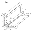
- the Eckprofilance is shown according to the first embodiment.
- the corner profile strip is produced by way of example from an aluminum strand part, which is cut to a predefinable cutting length I.
- the Eckprofilance is the basic structure of an angle profile with two mutually perpendicular abutment legs 1, each with the same material thickness m 1 and the same leg width b 1 are executed. Between the two abutment legs 1 of the angle section, a divider 3 is provided as a further leg in a 45 ° position, the leg width b 2 is reduced compared to the leg width b 1 and the material thickness m 2 is increased.
- the divider 3 and the two plant limb 1 run according to the Fig. 1 star-shaped in a node together.
- the divider 3 thus shares the defined between the plant legs Angular space in two wedge-shaped undercuts 5, which run in the direction of the node wedge-shaped.
- each of the marginal edges 7 of flooring elements 11 can be inserted.
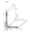
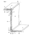
- a use case is shown in which the laid horizontally on a floor 13 flooring element 11 is brought up close to a side wall 15 and merges with the interposition of the Eckprofilance in the vertically established flooring element 11, which is mounted as a bottom skirting on the side wall 15 is.
- the two flooring elements 11 with their edges 7 on abutment surfaces 17 of the two abutment legs 1.
- the marginal edges 7 of the two flooring elements 11 are in abutting connection with lateral stop flanks 19 of the separating web 3.
- the web width b 2 ( Fig. 1 ) of the separating web 3 is dimensioned such that the distance a between the transition edges 21 and the facing stop legs 1 is slightly larger than the pad height h of the two flooring elements 11.
- the marginal edges 7 of the two flooring elements 11 at least slightly a small height offset inserted into the two slots 5 of the angle profile.
- the two bearing limbs 1 of the angle profile have according to the Fig. 1 and 2 At their outer ends in each case outwardly tapered outlet surfaces 25 in order to ensure a substantially stepless transition of the flooring elements 11 on the plant leg 1.
- the plant thighs 1 of the angle profile are in the Fig. 2 screwed in not shown manner in each case with the side wall 15 and with the bottom wall 13 and the grooved mounting surfaces 27 over a large area in contact with the side wall 15 and the bottom wall 13.
- a groove 29 is provided on the outer corner of the corner profile part.
- the front-side decorative surface 23 of the divider 3 forms according to the Fig. 2 a visually appealing transition between the two flooring elements 11.
- the decorative surface 23 extends strip-like along the in the Fig. 2 shown inside corner area.
- the width of the visible strip-shaped decorative surface 23 can be defined.
- the upper blank edge of the vertically raised flooring element 11 can be covered optically favorable in any way. It is particularly preferred to cover the upper edge by means of a well-known grout 31, as shown in the Fig. 2 is shown.
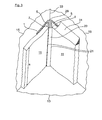
- the corner profile part is shown in another application.
- the two flooring elements 11 are each components of a guided around a room interior corner 33 floor skirting.
- the corner profile strip serves as an inner corner that connects the two flooring elements 11 together.
- the corner profile strip is not aligned horizontally, but positioned in a vertical position.
- the blank length I of the corner profile strip corresponds essentially to the base height s of the two flooring elements 11.
- the upper edge of the led around the room interior corner 33 floor skirting is again covered by a grout 31, as shown in the Fig. 3 partially indicated.
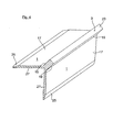
- the Eckprofilance according to the second embodiment is shown.
- the Eckprofilance also has an angle profile with two mutually perpendicularly aligned abutment legs 1, as already described with reference to the first embodiment.
- the corner profile of the Fig. 4 is therefore used as an outer corner connector, as exemplified in the Fig. 5 is shown.
- the flooring elements 11 a vertical riser 37 and a horizontal step 38 a step. At the upper outer edge at the transition between tread and riser 37, 38 is in the Fig.
- the inner mounting surfaces 27 are a large area in contact with the setting and step 37, 38.
- the outer contact surfaces 17 of the angle profile are each the flooring elements 11 with their edges 7 on.
- the marginal edges 7 are chamfered such that they are flat in abutting connection with the inclined lateral abutment edges 19 of the separating web 3.
- the frontal decorative surface 23 of the divider 3 is also exposed to the outside here.
- Fig. 6 is the Eckprofilance as an external corner connector part of a floor skirting board, which is guided around an outer space corner 41.
- the floor skirting board has flooring elements 11, which are connected to each other at the outer space corner 41 by means of Eckprofilmann. in the assembled state is the top of the guided around the room outer corner 41 floor skirting covered with grout 31.
- the frontal decorative surface 23 of the corner profile strip is exposed, which also serves as an edge protection.
Landscapes
- Engineering & Computer Science (AREA)
- Architecture (AREA)
- Civil Engineering (AREA)
- Structural Engineering (AREA)
- Floor Finish (AREA)
Applications Claiming Priority (1)
| Application Number | Priority Date | Filing Date | Title |
|---|---|---|---|
| DE202011001551U DE202011001551U1 (de) | 2011-01-14 | 2011-01-14 | Eckprofilleiste zur Verbindung von Bodenbelag-Elementen |
Publications (1)
| Publication Number | Publication Date |
|---|---|
| EP2476815A2 true EP2476815A2 (fr) | 2012-07-18 |
Family
ID=43799353
Family Applications (1)
| Application Number | Title | Priority Date | Filing Date |
|---|---|---|---|
| EP12000197A Withdrawn EP2476815A2 (fr) | 2011-01-14 | 2012-01-13 | Baguette de profilé d'angle pour la liaison d'éléments de revêtement de sol |
Country Status (2)
| Country | Link |
|---|---|
| EP (1) | EP2476815A2 (fr) |
| DE (1) | DE202011001551U1 (fr) |
Cited By (1)
| Publication number | Priority date | Publication date | Assignee | Title |
|---|---|---|---|---|
| RU238324U1 (ru) * | 2025-05-05 | 2025-10-24 | Денис Константинович Ишков | Встраиваемый плинтус |
Families Citing this family (3)
| Publication number | Priority date | Publication date | Assignee | Title |
|---|---|---|---|---|
| DE102012224309A1 (de) * | 2012-12-21 | 2014-06-26 | Protektorwerk Florenz Maisch Gmbh & Co. Kg | Winkelprofil |
| ES1086933Y (es) * | 2013-07-17 | 2013-11-06 | Gascon David Fernandez | Perfil de esquina para unir piezas cortadas en ángulo |
| CN116677151A (zh) * | 2023-06-19 | 2023-09-01 | 禾邑精智(上海)科技有限公司 | 阳角分隔型材、阳角结构及阳角结构施工方法 |
-
2011
- 2011-01-14 DE DE202011001551U patent/DE202011001551U1/de not_active Expired - Lifetime
-
2012
- 2012-01-13 EP EP12000197A patent/EP2476815A2/fr not_active Withdrawn
Cited By (1)
| Publication number | Priority date | Publication date | Assignee | Title |
|---|---|---|---|---|
| RU238324U1 (ru) * | 2025-05-05 | 2025-10-24 | Денис Константинович Ишков | Встраиваемый плинтус |
Also Published As
| Publication number | Publication date |
|---|---|
| DE202011001551U1 (de) | 2011-03-17 |
Similar Documents
| Publication | Publication Date | Title |
|---|---|---|
| EP1718818B1 (fr) | Dispositif de recouvrement pour rev tements de sol | |
| EP0477721A2 (fr) | Plafond suspendu à caissons | |
| DE202007018998U1 (de) | Verbindung für plattenförmige Bauelemente | |
| EP1400641A2 (fr) | Panneaux avec clip de fixation | |
| DE102006057491A1 (de) | Paneel sowie Bodenbelag | |
| DE102007019786B4 (de) | Verbindung für plattenförmige Bauelemente | |
| DE202007000310U1 (de) | Paneel sowie Bodenbelag | |
| WO2010149502A1 (fr) | Dispositif de profilé pour plancher | |
| DE102004029879B4 (de) | Paneele mit Umrandung insbesondere für Wände und Decken | |
| EP2476815A2 (fr) | Baguette de profilé d'angle pour la liaison d'éléments de revêtement de sol | |
| DE102015106035A1 (de) | Verbindung für plattenförmige Bauelemente und Feder | |
| AT509484B1 (de) | Haltevorrichtung zum verbinden von profilen zu einem flächigen wandelement | |
| DE202015009761U1 (de) | Leistenanordnung mit Verbindungselementen | |
| DE202011001550U1 (de) | Treppenkantenprofil | |
| EP1709887B1 (fr) | Connecteur d'angle pour garniture d'angle avec plinthes | |
| EP3693520A1 (fr) | Boite de nichage et/ou d'implantation pour animaux volants | |
| DE202016100187U1 (de) | Möbelplatte | |
| WO2008116489A1 (fr) | Système de baguette profilée doté d'un dispositif de recouvrement pour un escalier ouvert sur au moins une face frontale | |
| DE102005061645B4 (de) | Bodenbelag mit an beliebiger Stelle aus dem Verbund entfernbaren Paneelen | |
| EP2385188A2 (fr) | Agencement de plinthes | |
| DE10023165B4 (de) | Verbindung von zwei freistehenden Wandelementen | |
| AT14772U1 (de) | Paneel | |
| DE202013104859U1 (de) | Verlegeelement mit Verbindungsmitteln | |
| DE202015009811U1 (de) | Bodenbelag | |
| DE202015102468U1 (de) | Verlegesystem und Paneel zur flächigen Verlegung und flächige Verkleidung |
Legal Events
| Date | Code | Title | Description |
|---|---|---|---|
| PUAI | Public reference made under article 153(3) epc to a published international application that has entered the european phase |
Free format text: ORIGINAL CODE: 0009012 |
|
| AK | Designated contracting states |
Kind code of ref document: A2 Designated state(s): AL AT BE BG CH CY CZ DE DK EE ES FI FR GB GR HR HU IE IS IT LI LT LU LV MC MK MT NL NO PL PT RO RS SE SI SK SM TR |
|
| AX | Request for extension of the european patent |
Extension state: BA ME |
|
| STAA | Information on the status of an ep patent application or granted ep patent |
Free format text: STATUS: THE APPLICATION IS DEEMED TO BE WITHDRAWN |
|
| 18D | Application deemed to be withdrawn |
Effective date: 20160802 |