EP2476819A1 - Support pour planches ou panneaux de plancher - Google Patents
Support pour planches ou panneaux de plancher Download PDFInfo
- Publication number
- EP2476819A1 EP2476819A1 EP12000099A EP12000099A EP2476819A1 EP 2476819 A1 EP2476819 A1 EP 2476819A1 EP 12000099 A EP12000099 A EP 12000099A EP 12000099 A EP12000099 A EP 12000099A EP 2476819 A1 EP2476819 A1 EP 2476819A1
- Authority
- EP
- European Patent Office
- Prior art keywords
- gripper
- base
- holder
- hook
- boards
- Prior art date
- Legal status (The legal status is an assumption and is not a legal conclusion. Google has not performed a legal analysis and makes no representation as to the accuracy of the status listed.)
- Withdrawn
Links
Images


Classifications
-
- E—FIXED CONSTRUCTIONS
- E04—BUILDING
- E04F—FINISHING WORK ON BUILDINGS, e.g. STAIRS, FLOORS
- E04F15/00—Flooring
- E04F15/02—Flooring or floor layers composed of a number of similar elements
- E04F15/10—Flooring or floor layers composed of a number of similar elements of other materials, e.g. fibrous or chipped materials, organic plastics, magnesite tiles, hardboard, or with a top layer of other materials
-
- E—FIXED CONSTRUCTIONS
- E04—BUILDING
- E04F—FINISHING WORK ON BUILDINGS, e.g. STAIRS, FLOORS
- E04F15/00—Flooring
- E04F15/02—Flooring or floor layers composed of a number of similar elements
- E04F15/02044—Separate elements for fastening to an underlayer
- E04F2015/0205—Separate elements for fastening to an underlayer with load-supporting elongated furring elements between the flooring elements and the underlayer
- E04F2015/02066—Separate elements for fastening to an underlayer with load-supporting elongated furring elements between the flooring elements and the underlayer with additional fastening elements between furring elements and flooring elements
- E04F2015/02077—Separate elements for fastening to an underlayer with load-supporting elongated furring elements between the flooring elements and the underlayer with additional fastening elements between furring elements and flooring elements the additional fastening elements located in-between two adjacent flooring elements
- E04F2015/02094—Engaging side grooves running along the whole length of the flooring elements
Definitions
- the invention relates to a holder for planks, boards od. Like. According to the preamble of claim 1, as for example from the JP 2007 009 412 A is known.
- Planks or the like with known brackets to beams. can not be removed individually from the beams without destroying the boards or the brackets.
- the object of the invention is therefore to provide a holder for planks, boards or the like. to provide that allows a release of individual planks, boards od. Like. From a series of pavements fixed without destruction. Furthermore, it is an object of the invention to be able to produce such holders as inexpensively as possible.
- the holder is od for boards, boards od. Like. Provided having grooves in opposite narrow sides.
- the holder has a central axis extending parallel to the groove through the holder. With respect to the central axis opposite each other, the holder has at least two springs. In each case one of the springs is provided for engagement in one of the grooves, so that two adjacent planks can be held by the holder.
- the springs are aligned parallel to the central axis and act at least in a direction perpendicular to the central axis as fasteners together to od the planks, boards od. Like. Keep on a substrate.
- the holder consists of at least two parts, namely at least a base and a gripper, which are detachably connectable to each other, wherein the base of the substrate can be fastened and the gripper od the springs for engagement in the planks, boards od.
- An access to the gripper is ensured for a release of the gripper from the base from the outside through a gap between the fixed planks. So the gripper can be transferred from a mounting position to a released position.
- the releasable connection between the gripper and the base is designed as a hooked connection, wherein the base has a first hook and the gripper has a second hook, or both hooks are arranged on one of the parts, and the hooks are arranged spaced from each other along the central axis. Each of the hooks can be brought into engagement with the respective other part of the holder.
- the gripper is designed such that the gripper engages in the base when the gripper is moved from a released position into the fastening position.
- a release from the locked mounting position is possible only by overcoming a resistance.
- the resistance is due to the fact that to release from the latched fastening position executed in the gripper, a convex nose is brought out of a executed in the base concave trough.
- a reverse arrangement of the nose and trough in the respective other part of the holder is a feature of a further advantageous embodiment of the holder.
- At least one of the hooks is designed as a solid hook and formed from the material of the base or the gripper, in particular erected or bent out of a steel sheet.
- either the gripper or the base or both parts of the holder to the respective hook of the other part corresponding to a along the central axis aligned, tapered slot into which the hook is inserted, so that the hook engages behind the other part, as soon as the locked position is taken.
- the base and / or the gripper is made of sheet steel.
- non-ferrous metals and rust-proof stainless steel were available for a sheet with material-specific advantages.
- Mounts according to the invention are preferably used in terrace construction.
- the holder according to the invention enables a single board of a finished fixed row of boards to be detached from a beam. This requires engagement by a gap between two planks on the gripper, so that the gripper along the gap along the longitudinal axis can be moved and can be solved from the locked position. In the same way, another gripper is released by an adjacent gap, so that the plank located between the two columns is no longer firmly connected to the beam. There will be no destruction. Even grippers that have already been fastened and loosened can be reused with a new board.
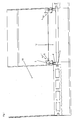
- FIGS. 1 to 6 show an embodiment of a holder 1 according to the invention, wherein the FIGS. 1 and 2 the T-shaped bracket seen in cross-section in their installation situation with at least one fixed board 10 represent.
- the FIGS. 3a, 3b and 4 show the holder 1 as a two-part holder consisting of a base 2 and a gripper 3.
- the FIGS. 5 and 6 show only the base 2 in a top and a side view. Like parts are designated by like reference numerals.
- the boards 10 are mounted on a beam 12.
- the planks 10 have, in a narrow side, a groove 11 which is aligned parallel to a central axis 4 extending through the holder and into which the holder 1 engages with its gripper 3.
- the holder 1 is bolted to its base 2 on the beam 12.
- the base 2 has according to the illustrated embodiment, a U-shaped cross-section and is formed of sheet steel.
- the base 2 is the vertical leg of the T-shaped bracket 1.
- the central axis 4 extends, wherein approximately centrally a passage opening is provided in the base 2, through which the base 2 can be screwed to the beam 12, so the base 2 is aligned parallel to the fastening planks 10.
- the base 2 Spaced from the passage opening, the base 2 has a trough 13, which is arranged facing the gripper 3, so that a nose of the gripper 3 engages at the level of the trough 13 in the trough 13 when the gripper 3 reaches the locked position.
- the base 2 also has aligned along the central axis 4 a out of the steel sheet to the gripper 3 out bent first hook 6, which therefore arranged facing the gripper and is intended to engage in a slot 9 of the gripper 3. In the locked position, the first hook 6 engages behind the gripper 3.
- the gripper 3 is pushed along the central axis 4, for example, through the groove 11 on the base 2 until they are in a locked position ( Fig. 4 ) snaps into the base 2.
- the gripper 3 forms the horizontal leg of the T-shaped holder 1 and has at both ends of the horizontal leg a spring 5 which is intended for engagement in the groove 11.
- the springs 5 are arcuately bent away from the steel sheet of the gripper 3 of the base 2 facing upwards. Depending on the geometry of the grooves 11, the gripper 3 with its springs 5, the grooves 11 are adjusted accordingly. Also, the springs 5 can be made elastically deformable, so that a complete or almost complete engagement in the groove 11 succeeds.
- the gripper 3 has the tapered slot 9 as intended to receive the first hook 6.
- the slot 9 facing away from the gripper 3 on the other end a second hook 7, which faces the base 2 is exposed from the steel sheet down.
- the second hook 7 engages in the U-shaped cross section of the base 2, so that the second hook 7 engages behind the base 2 when the locked position is reached.
- the geometries of the hooks 6, 7, 9 of the slot and the U-shaped cross-section of the base 2 also avoid tilting of the parts of the holder 1 when they are to be brought out of the locked mounting position in a released position, especially if a single plank is to be removed from a series of planks.
- a tool can be inserted through a gap between the planks 10 in a recess of the gripper 3 to move the gripper 3 against the base 2 along the central axis 4 until the hooks 6, 7 no longer the other part of the holder 1 engage behind.
- the recess can be designed particularly advantageously in such a way in the gripper 3 as a through hole arranged above the passage opening of the base 2, so that the screwing of the base 2 onto the beam 2 can be achieved by the gripper 3.
- the gripper 3 should the gripper 3 be blocked in any way, alternatively, the holder 1 can be released without destruction from the beam 12 by the one screw is released.
- the release from the locked mounting position is possible only by overcoming a resistance.
- the resistance is in the illustrated embodiment ( Fig. 6 ) due to the fact that in the locked position fastening a not shown nose of the gripper 3 is immersed in the trough 13 of the base 2.
Landscapes
- Engineering & Computer Science (AREA)
- Architecture (AREA)
- Civil Engineering (AREA)
- Structural Engineering (AREA)
- Clamps And Clips (AREA)
Applications Claiming Priority (1)
| Application Number | Priority Date | Filing Date | Title |
|---|---|---|---|
| DE102011008432A DE102011008432A1 (de) | 2011-01-12 | 2011-01-12 | Halterung für Dielen, Bretter oder dergleichen |
Publications (1)
| Publication Number | Publication Date |
|---|---|
| EP2476819A1 true EP2476819A1 (fr) | 2012-07-18 |
Family
ID=45531159
Family Applications (1)
| Application Number | Title | Priority Date | Filing Date |
|---|---|---|---|
| EP12000099A Withdrawn EP2476819A1 (fr) | 2011-01-12 | 2012-01-11 | Support pour planches ou panneaux de plancher |
Country Status (2)
| Country | Link |
|---|---|
| EP (1) | EP2476819A1 (fr) |
| DE (1) | DE102011008432A1 (fr) |
Cited By (8)
| Publication number | Priority date | Publication date | Assignee | Title |
|---|---|---|---|---|
| FR3001481A1 (fr) * | 2013-01-29 | 2014-08-01 | Neolife | Lame de terrasse |
| EP2816172A3 (fr) * | 2013-06-14 | 2015-04-15 | Novo-Tech GmbH & Co. KG | Système de montage pour un revêtement de sol |
| EP3453814A1 (fr) * | 2017-09-11 | 2019-03-13 | Günther Gaisbauer | Système de terrasse et élément de fixation permettant de fixer deux profils apparents |
| US12129663B2 (en) | 2017-08-15 | 2024-10-29 | National Nail Corp. | Hidden fastener unit and related method of use |
| US12234654B2 (en) | 2017-08-15 | 2025-02-25 | National Nail Corp. | Hidden fastener unit and related method of use |
| US12264483B2 (en) | 2017-08-15 | 2025-04-01 | National Nail Corp. | Hidden fastener unit and related method of use |
| US12297649B2 (en) | 2022-10-27 | 2025-05-13 | Primesource Building Products, Inc. | Deck clip |
| US12365065B2 (en) | 2022-08-02 | 2025-07-22 | National Nail Corp. | Clip starter guide and related method of use |
Citations (3)
| Publication number | Priority date | Publication date | Assignee | Title |
|---|---|---|---|---|
| JP2007009412A (ja) | 2005-06-28 | 2007-01-18 | Tatatomi Noro | 床材連結金具および床材連結方法 |
| JP2008031827A (ja) * | 2006-06-28 | 2008-02-14 | Masatoshi Tamaoki | 長尺板材の固定構造、長尺板材固定具、及び長尺板材 |
| DE202007002282U1 (de) * | 2007-02-16 | 2008-06-19 | Möller GmbH & Co. KG | Profilelemente |
Family Cites Families (2)
| Publication number | Priority date | Publication date | Assignee | Title |
|---|---|---|---|---|
| GB2234991A (en) * | 1989-08-16 | 1991-02-20 | Stephenson Airey Trevor | Demountable flooring, platforms and staging |
| DE202008001033U1 (de) * | 2008-01-22 | 2008-03-27 | Rauschenberger, Udo | Halterung (Terrassenclip) |
-
2011
- 2011-01-12 DE DE102011008432A patent/DE102011008432A1/de not_active Withdrawn
-
2012
- 2012-01-11 EP EP12000099A patent/EP2476819A1/fr not_active Withdrawn
Patent Citations (3)
| Publication number | Priority date | Publication date | Assignee | Title |
|---|---|---|---|---|
| JP2007009412A (ja) | 2005-06-28 | 2007-01-18 | Tatatomi Noro | 床材連結金具および床材連結方法 |
| JP2008031827A (ja) * | 2006-06-28 | 2008-02-14 | Masatoshi Tamaoki | 長尺板材の固定構造、長尺板材固定具、及び長尺板材 |
| DE202007002282U1 (de) * | 2007-02-16 | 2008-06-19 | Möller GmbH & Co. KG | Profilelemente |
Cited By (11)
| Publication number | Priority date | Publication date | Assignee | Title |
|---|---|---|---|---|
| FR3001481A1 (fr) * | 2013-01-29 | 2014-08-01 | Neolife | Lame de terrasse |
| EP2816172A3 (fr) * | 2013-06-14 | 2015-04-15 | Novo-Tech GmbH & Co. KG | Système de montage pour un revêtement de sol |
| US12129663B2 (en) | 2017-08-15 | 2024-10-29 | National Nail Corp. | Hidden fastener unit and related method of use |
| US12234654B2 (en) | 2017-08-15 | 2025-02-25 | National Nail Corp. | Hidden fastener unit and related method of use |
| US12264483B2 (en) | 2017-08-15 | 2025-04-01 | National Nail Corp. | Hidden fastener unit and related method of use |
| US12607020B2 (en) | 2017-08-15 | 2026-04-21 | National Nail Corp. | Hidden fastener unit and related method of use |
| EP3453814A1 (fr) * | 2017-09-11 | 2019-03-13 | Günther Gaisbauer | Système de terrasse et élément de fixation permettant de fixer deux profils apparents |
| US12365065B2 (en) | 2022-08-02 | 2025-07-22 | National Nail Corp. | Clip starter guide and related method of use |
| US12297649B2 (en) | 2022-10-27 | 2025-05-13 | Primesource Building Products, Inc. | Deck clip |
| US12352054B2 (en) | 2022-10-27 | 2025-07-08 | Primesource Building Products, Inc. | Deck clip |
| US12442198B2 (en) | 2022-10-27 | 2025-10-14 | Primesource Building Products, Inc. | Deck clip |
Also Published As
| Publication number | Publication date |
|---|---|
| DE102011008432A1 (de) | 2012-07-12 |
Similar Documents
| Publication | Publication Date | Title |
|---|---|---|
| EP2476819A1 (fr) | Support pour planches ou panneaux de plancher | |
| EP2815190B1 (fr) | Dispositif de retenue pour un module solaire | |
| DE3886409T2 (de) | Werkzeughalter auf lochplatten. | |
| DE102004006211B4 (de) | Verbindungsvorrichtung | |
| DE69514817T2 (de) | Tragvorrichtung für abgehängte decken | |
| EP3009581B1 (fr) | Système de façade et élément de retenue destiné à fixer des profilés visibles | |
| EP1987213A1 (fr) | Systeme de coffrage de plafond | |
| DE3122505A1 (de) | Festsetzstueck fuer wand- oder abschirmelemente | |
| EP3384108B1 (fr) | Pièce de coffrage et coffrage de dalles comprenant une telle pièce de coffrage | |
| EP2789772A1 (fr) | Support pour un sabot de guidage d'un système de grimpant pour des coffrages en béton | |
| EP1442942A1 (fr) | Raccord à brides entre un longeron de véhicule et un élément de support fixable à ce dernier | |
| EP1899552B1 (fr) | Systeme de coffrage de plafond | |
| EP3440281A1 (fr) | Ferrure pour une plinthe d'un échafaudage | |
| EP3712354B1 (fr) | Plateforme de coffrage | |
| DE19819774A1 (de) | Verbinder für Verstärkungsstäbe | |
| DE202006005470U1 (de) | Klammer zur Befestigung von Paneelelementen | |
| EP0472760A1 (fr) | Clôture | |
| DE10048825B4 (de) | Stapelbox | |
| DE102010055547B4 (de) | Kabeltragsystem umfassend eine Konsole und eine Gitterrinne | |
| EP3461963B1 (fr) | Système porteur et système d'éléments de connexion permettant la connexion des porteurs | |
| EP0049431A2 (fr) | Faux-plafond à résilles | |
| EP0947641B1 (fr) | Dispositif pour positionner de manière coulissante des éléments de construction | |
| WO2016172750A1 (fr) | Dispositif de fixation pour un panneau frontal et meuble ainsi équipé | |
| DE19722810C2 (de) | Vorrichtung zur Kabelkanalbefestigung an Traversen | |
| EP0430271B1 (fr) | Grille de plafond suspendu |
Legal Events
| Date | Code | Title | Description |
|---|---|---|---|
| PUAI | Public reference made under article 153(3) epc to a published international application that has entered the european phase |
Free format text: ORIGINAL CODE: 0009012 |
|
| AK | Designated contracting states |
Kind code of ref document: A1 Designated state(s): AL AT BE BG CH CY CZ DE DK EE ES FI FR GB GR HR HU IE IS IT LI LT LU LV MC MK MT NL NO PL PT RO RS SE SI SK SM TR |
|
| AX | Request for extension of the european patent |
Extension state: BA ME |
|
| 17P | Request for examination filed |
Effective date: 20120627 |
|
| STAA | Information on the status of an ep patent application or granted ep patent |
Free format text: STATUS: THE APPLICATION IS DEEMED TO BE WITHDRAWN |
|
| 18D | Application deemed to be withdrawn |
Effective date: 20150804 |