EP2476827B1 - Dispositif de verrouillage - Google Patents
Dispositif de verrouillage Download PDFInfo
- Publication number
- EP2476827B1 EP2476827B1 EP11151046.7A EP11151046A EP2476827B1 EP 2476827 B1 EP2476827 B1 EP 2476827B1 EP 11151046 A EP11151046 A EP 11151046A EP 2476827 B1 EP2476827 B1 EP 2476827B1
- Authority
- EP
- European Patent Office
- Prior art keywords
- locking device
- latch bolt
- recited
- blocking element
- latch
- Prior art date
- Legal status (The legal status is an assumption and is not a legal conclusion. Google has not performed a legal analysis and makes no representation as to the accuracy of the status listed.)
- Active
Links
Images
Classifications
-
- E—FIXED CONSTRUCTIONS
- E05—LOCKS; KEYS; WINDOW OR DOOR FITTINGS; SAFES
- E05B—LOCKS; ACCESSORIES THEREFOR; HANDCUFFS
- E05B63/00—Locks or fastenings with special structural characteristics
- E05B63/18—Locks or fastenings with special structural characteristics with arrangements independent of the locking mechanism for retaining the bolt or latch in the retracted position
- E05B63/20—Locks or fastenings with special structural characteristics with arrangements independent of the locking mechanism for retaining the bolt or latch in the retracted position released automatically when the wing is closed
- E05B63/202—Locks or fastenings with special structural characteristics with arrangements independent of the locking mechanism for retaining the bolt or latch in the retracted position released automatically when the wing is closed a latch bolt being initially retained in an intermediate position and subsequently projected to its full extent when the wing is closed
-
- E—FIXED CONSTRUCTIONS
- E05—LOCKS; KEYS; WINDOW OR DOOR FITTINGS; SAFES
- E05B—LOCKS; ACCESSORIES THEREFOR; HANDCUFFS
- E05B63/00—Locks or fastenings with special structural characteristics
- E05B63/0056—Locks with adjustable or exchangeable lock parts
Definitions
- the invention relates to a locking device for a door or a window with a lock case and a slidable latch disposed therein, which can assume an open position, a closed position and a locking position, wherein the latch bolt has a latch shaft and with a latch bolt from the closed position to the locking position is provided over-converting blocking element, wherein the locking device also has an additional case, wherein in the lock case a displacement of the latch bolt from the closed position to the blocking position blocking blocking element is provided, the latch bolt has a locking element on which the blocking element engages and the blocking element by means of the additional trap the way of the locking element is led out.
- Such a device is eg off US 5469723 known, which corresponds to the preamble of claim 1.
- a mortise lock is also from the EP 0 431 369 A2 known. Its latch bolt protrudes, as in conventional latch mortise locks, in the door open position only with its frontal bevel out of the lock cuff out, but offers the latter over the advantage that the latch bolt automatically moves deeper into the door frame side located in the door closing position lock plate, which even greater security against breakage of the door is achieved by this deep closing engagement. In addition, the latch bolt in its fully extended locking position in which its ramp in the strike plate completely disappears, not by unauthorized introduction of a sufficiently solid object, such as a flexible sheet, screwdriver or a check card, are moved back into the door gap located between the door lock and strike plate, as is easily possible with simple latch locks.
- a sufficiently solid object such as a flexible sheet, screwdriver or a check card
- the DE 44 07 244 C1 and the DE 197 01 761 C1 show locks with an auxiliary trap, via which a slide plate is controlled, which locks the bolt and / or the trap separately. A manipulation of the latch bolt is thus not readily possible.
- the invention has for its object a locking device to provide, which has an even higher security against manipulation.
- the locking element is formed by a pin projecting transversely to the direction of displacement of the latch bolt transversely to the direction of displacement of the blocking element.
- the displacement of the latch bolt is blocked or prevented if it is not operated properly.
- the shutter located in the latch bolt can still be operated with the door open, but this does not cause the latch bolt is moved from its closed position to the locked position.
- the latch bolt is unlocked in its closed position, but can not continue to extend because its displacement is blocked in the outward direction.
- the door can be closed easily because the latch bolt can continue to be inserted, because he stands only with his, the case slope having portion of the cuff.
- the locking element is displaceable in the direction of displacement of the latch bolt.
- This locking member has the task of preventing a shift of the latch bolt, if the door has not been closed properly. Since the locking element is in the lock case, it is protected against manipulation.
- the invention provides that the locking element is formed by a transverse to the displacement direction of the latch bolt transversely to the direction of displacement of the blocking element projecting pin.
- This Spigot is either integrally formed on the latch bolt or bolted with this.
- the pin is located on the falling shaft, so that its position within the lock box is always the same and independent of the box width and the backset.
- the blocking element is mounted transversely to the displacement direction of the latch bolt and in particular in the plane of the lock box or mortise lock and / or pivotally mounted in the lock box. This makes it simple in a simple manner possible that the blocking element can assume a position in which it is collision-free to the latch bolt or engages in its displacement and can block this.
- the blocking element has an open-edge recess opposite to the sliding direction of the latch bolt.
- the pin is advantageously caught, so that in the blocking position of the blocking element, the locking element is located in the recess.
- the latch bolt can continue to be inserted into the lock box, since the pin leave the recess in the direction of insertion of the latch bolt, i. can emerge.
- the additional trap In order to be able to easily transfer the movement of the additional trap, in particular its insertion movement, to the blocking element, the additional trap is coupled to a drive for the blocking element.
- the direction of movement and / or the length of the insertion of the additional trap can be adapted to the requirements of the blocking element.
- the displacement movement of the additional trap is disconnected via the drive from the blocking element. This is necessary, for example, in the event that the additional case is inadvertently or unintentionally operated manually when the door is not closed.
- a preferred embodiment of the invention provides that the drive has a drive housing and a die displaceably mounted in the drive housing.
- the additional latch engages an end face of the punch, wherein the punch is supported with its opposite end face against the force of a first spring on the drive housing.
- the position of the additional trap is thus transmitted directly to the stamp, whereas the position of the punch is transmitted force-dependent on the drive housing. If the counterforce is greater than the force of the first spring, then the drive housing remains in its current position and the first spring is compressed.
- the drive housing is slidably mounted in the lock box.
- the drive housing drives a pivot lever which engages with a first pivot arm on the blocking element.
- the swivel arm has the advantage that the required leverage for moving or pivoting the blocking element can be adjusted as needed via him.
- the storage of the pivot arm is relatively easy, since it only requires a journal.
- a development of the invention provides that the pivot lever is urged via a second spring in a blocking position corresponding to the blocking element corresponding rest position.
- This second spring generates the counterforce for the first spring and serves to return the pivot lever and the blocking element in the initial or blocking position.
- the spring force of the first spring on the punch is greater than the spring force of the second spring on the pivot lever.
- the spring force of the second spring is thus overcome by the drive, so that the pivot lever and the blocking element are actuated.
- the blocking element is held when the latch bolt assumes its closed position and not in his Open position has been transferred, then the first spring is compressed as soon as the punch is displaced.
- the free end of the first pivoting arm runs in a slot of the blocking element.
- the scenery is advantageously realized by a pin-groove connection.
- a preferred connection of drive housing and pivot lever is achieved in that the pivot lever has a second pivot arm and the free end of the second pivot arm engages in a recess on the drive housing.
- the recess on the drive housing operates in the manner of a rack, whereas the free end of the second pivot arm acts as a tooth engaging in the rack.
- the position of the additional trap with respect to the punch is adjustable positionable. This is done by the additional trap more or less inserted into the stamp and the desired position can be locked.
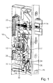
- FIG. 1 shows a section of a total of 10 designated locking device with a lock box 12 in which a latch bolt 14 is slidably guided.
- a plastic-sheathed and thus sound-insulated additional trap 16 can be seen, which is also arranged in the lock box 12 in this embodiment. But it could also be accommodated in an additional box, wherein the additional box is mechanically coupled via suitable connecting means with the lock box 12.
- the latch bolt 14 takes in the FIG. 1 its locking position and is fully extended from the lock box 12, which is done via a latch spring 18 which is supported on the lock box 12 and engages the rear of a latch shaft 20 of the latch bolt 14.
- a blocking element 22 which is mounted displaceably in the vertical direction in the lock case 12, and a pivot lever 24 can be seen, which is pivotally mounted about a pin 26 and a first pivot arm 28 and a second pivot arm 30 has.
- the additional trap 16 is connected to a drive 32, which will be described in detail later.
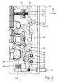
- FIG. 2 shows the lock case 12 in the closed position
- Hopkins latch bolt 14 projects beyond a cuff 34 only with its trailing edge.
- a locking element 36 in the form of a transversely (orthogonally) projecting towards the displacement pin 40 which engages in an open-edged recess 42 at the end of the blocking element 22.
- the recess 42 is open against the direction of displacement 38 and holds the pin 40 positively fixed.
- the blocking element 22 also extends transversely to the direction of displacement 38 and transversely to the locking element 36 and is mounted in the extension direction, ie vertically displaceable.
- the blocking element 22 on a curved or curved slot 44, which is part of a link 46, to which still belongs in the slot 44 engaging pin 48 which protrudes from the end of the first pivot arm 28.
- the end of the second pivot arm 30 engages in a recess 50 of the drive 32nd
- the drive 32 has a punch 52 and a punch 52 receiving the drive housing 54, on which the recess 50 is provided.
- the additional latch 16 is mounted and the punch 52 is supported by means of a first spring 56, a coil spring, at the bottom of the drive housing 54 from.
- a second spring 58 a leg spring, recognizable, which is looped around the pin 26 and urges the pin 48 in the counterclockwise direction.
- the spring force of the second spring 58 is smaller than the spring force of the first spring 56.
- the additional trap 16 As in the FIG. 2 shown, inserted, then the punch 52 is displaced. Since the spring force of the first spring 56 is greater than the spring force of the second spring 58, the punch 52 displaces the drive housing 54 in the direction of displacement of the additional latch 16, whereby the pivot lever 24 via the second pivot arm 30 in Is pivoted clockwise and thereby biases the second spring 58.
- the pin 48 moves to the other end of the slot 44, whereby the blocking element 22 is moved downward. This occurs when closing the door, in which the latch bolt 14 is inserted into the lock box 12, whereby the pin 40 is pushed to the left, ie from the recess 42 of the blocking element 22.
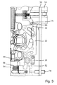
- the latch bolt 14 snaps into the latch receptacle of the striker plate on the fixed frame when the door is closed, then the latch bolt 14 moves from its open position to the closed position FIG. 3 in the locked position according to FIG. 1 , The additional trap 16 can remain pressed.
- the additional trap 16 but also moves out of the lock box 12, so that the blocking element 22 again assumes its initial position, in which it is pushed by the gate 46, supported by the second spring 48.
- the pin 40 is then located between the cuff 34 and the blocking element 22, which has at its end a nose 60 which secures the position of the pin 40.
- the latch bolt 14 can not be pressed into the lock box 12 by means of a tool.
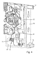
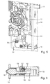
- FIG. 4 shows the same situation and position of the components, like the FIG. 2 . If the additional trap 16, as in FIG. 4 shown, for manipulation purposes, for example, manually pressed into the lock box 12, then the punch 52 is moved. However, the drive housing 54 is blocked by the captured via the pin 40 blocking element 22 and the pivot lever 24, so that the first spring 56 is compressed. As soon as the additional latch 16 is released, it is again pushed out of the lock box 12 via the first spring 56.
- the FIG. 6 finally shows a device with which the supernatant of the additional trap 16 can be adjusted via the cuff 34.
- the additional latch 16 has a latch shaft 62 which is mounted in the punch 52. On the latch shaft 62 are adjacent to each other in the manner of a rack a plurality of indentations 64, in which the tip of a grub screw 66 engages, which is screwed into the punch 52. If the supernatant of the additional latch 16 is adjusted, the grub screw 66 is loosened, the position of the latch shaft 62 in the plunger 52 changed and the grub screw 66 fixed in such a way that it engages in another notch 64.
Landscapes
- Engineering & Computer Science (AREA)
- Structural Engineering (AREA)
- Lock And Its Accessories (AREA)
Claims (14)
- Dispositif de verrouillage (10) pour une porte ou une fenêtre, avec un coffre de serrure (12) et un pêne de loquet (14) qui est disposé à déplacement dans celui-ci et qui est apte à occuper une position ouverte, une position de fermeture et une position de verrouillage, ledit pêne de loquet (14) présentant une tige de loquet (20) et étant pourvu d'un élément d'arrêt qui fait passer ledit pêne de loquet (14) de la position de fermeture à la position de verrouillage, et avec un loquet supplémentaire (16), dans ledit coffre de serrure (12) étant prévu un élément de blocage (22) qui bloque un déplacement dudit pêne de loquet (14) de la position de fermeture dans la position de verrouillage, ledit pêne de loquet (14) présentant un élément d'arrêt (36) sur lequel se prend ledit élément de blocage (22), et ledit élément de blocage (22) étant mené hors du chemin de l'élément d'arrêt (36) au moyen dudit loquet supplémentaire (16), caractérisé par le fait que ledit élément d'arrêt (36) est constitué par un tenon (40) faisant saillie transversalement à la direction de déplacement du pêne de loquet (14) transversale à la direction de déplacement de l'élément de blocage (22).
- Dispositif de verrouillage selon la revendication 1, caractérisé par le fait que ledit élément d'arrêt (36) est déplaçable dans la direction de déplacement du pêne de loquet (14).
- Dispositif de verrouillage selon l'une quelconque des revendications précédentes, caractérisé par le fait que ledit élément de blocage (22) est logé dans le coffre de serrure (12) de manière à être déplaçable transversalement à la direction de déplacement du pêne de loquet (14).
- Dispositif de verrouillage selon l'une quelconque des revendications précédentes, caractérisé par le fait que ledit élément de blocage (22) présente un évidement (42) à bord ouvert opposé à la direction de sortie (38) du pêne de loquet (14).
- Dispositif de verrouillage selon la revendication 4, caractérisé par le fait que, dans la position de blocage, l'élément d'arrêt (36) est situé dans ledit évidement (42).
- Dispositif de verrouillage selon l'une quelconque des revendications précédentes, caractérisé par le fait que ledit loquet supplémentaire (16) est couplé à un mécanisme d'entraînement (32) pour ledit élément de blocage (22).
- Dispositif de verrouillage selon la revendication 6, caractérisé par le fait que ledit mécanisme d'entraînement (32) présente un boîtier de mécanisme d'entraînement (54) et un pilon (52) logé à déplacement à l'intérieur du boîtier de mécanisme d'entraînement (54).
- Dispositif de verrouillage selon la revendication 7, caractérisé par le fait que ledit loquet supplémentaire (16) se prend sur une face frontale dudit pilon (52) et que le pilon (52) s'appuie par sa face frontale opposée, à l'encontre de la force d'un premier ressort (56), sur le boîtier de mécanisme d'entraînement (54).
- Dispositif de verrouillage selon la revendication 7 ou 10, caractérisé par le fait que le boîtier de mécanisme d'entraînement (54) entraîne un levier de pivotement (24) qui se prend sur ledit élément de blocage (22) par un premier bras de pivotement (28).
- Dispositif de verrouillage selon la revendication 9, caractérisé par le fait que ledit levier de pivotement (24) est poussé par un deuxième ressort (58) dans une position de repos correspondant à la position de blocage pour ledit élément de blocage (22).
- Dispositif de verrouillage selon la revendication 8 et 10, caractérisé par le fait que la force de ressort du premier ressort (56) exercée sur ledit pilon (52) est plus importante que la force de ressort du deuxième ressort (58) exercée sur le levier de pivotement (24).
- Dispositif de verrouillage selon l'une quelconque des revendications 9 à 11, caractérisé par le fait que l'extrémité libre du premier bras de pivotement (28) se déplace dans une coulisse (46) de l'élément de blocage (22).
- Dispositif de verrouillage selon l'une quelconque des revendications 9 à 12, caractérisé par le fait que ledit levier de pivotement (24) présente un deuxième bras de pivotement (30) et que l'extrémité libre du deuxième bras de pivotement (30) s'engage dans un évidement (50) ménagé sur le boîtier de mécanisme d'entraînement (54).
- Dispositif de verrouillage selon l'une quelconque des revendications 7 à 13, caractérisé par le fait que la position dudit loquet supplémentaire (16) par rapport au pilon (52) est positionnable de façon réglable.
Priority Applications (1)
| Application Number | Priority Date | Filing Date | Title |
|---|---|---|---|
| EP11151046.7A EP2476827B2 (fr) | 2011-01-14 | 2011-01-14 | Dispositif de verrouillage |
Applications Claiming Priority (1)
| Application Number | Priority Date | Filing Date | Title |
|---|---|---|---|
| EP11151046.7A EP2476827B2 (fr) | 2011-01-14 | 2011-01-14 | Dispositif de verrouillage |
Publications (3)
| Publication Number | Publication Date |
|---|---|
| EP2476827A1 EP2476827A1 (fr) | 2012-07-18 |
| EP2476827B1 true EP2476827B1 (fr) | 2013-12-11 |
| EP2476827B2 EP2476827B2 (fr) | 2020-09-09 |
Family
ID=44260879
Family Applications (1)
| Application Number | Title | Priority Date | Filing Date |
|---|---|---|---|
| EP11151046.7A Active EP2476827B2 (fr) | 2011-01-14 | 2011-01-14 | Dispositif de verrouillage |
Country Status (1)
| Country | Link |
|---|---|
| EP (1) | EP2476827B2 (fr) |
Family Cites Families (9)
| Publication number | Priority date | Publication date | Assignee | Title |
|---|---|---|---|---|
| DE3241273A1 (de) † | 1982-11-09 | 1984-05-10 | Heinz Dipl.-Ing. 4044 Kaarst Thieme | Tuerschloss, selbsttaetig verriegelnd, insbesondere fuer haus- und wohnungsabschlusstueren |
| DE8914367U1 (de) | 1989-12-06 | 1991-04-04 | BKS GmbH, 5620 Velbert | Einsteckschloß mit Fallenriegel |
| US5469723A (en) * | 1990-07-25 | 1995-11-28 | Litwin; Noel | Safety locks |
| DE9207865U1 (de) † | 1992-06-11 | 1992-09-10 | Wilhelm Dörrenhaus GmbH & Co KG, 5620 Velbert | Durch einen Schlüssel- und/oder durch einen Drücker betätigbares Antipanik-Hotelschloß |
| DE4407244C1 (de) | 1994-03-04 | 1995-08-17 | Fuss Fritz Gmbh & Co | Selbstverriegelndes Schloß |
| DE19546466C1 (de) † | 1995-12-13 | 1997-01-30 | Steinbach & Vollmann | Sicherheitsschloß |
| DE19546467C1 (de) † | 1995-12-13 | 1997-07-03 | Steinbach & Vollmann | Sicherheitsschloß |
| DE19701761C1 (de) | 1997-01-20 | 1998-04-16 | Fuss Fritz Gmbh & Co | Selbstverriegelndes Schloß |
| ES2211277B1 (es) * | 2002-04-10 | 2005-10-01 | La Industrial Cerrajera, S.A. | Cerradura de seguridad con doble control del picaporte y funcion antipanico. |
-
2011
- 2011-01-14 EP EP11151046.7A patent/EP2476827B2/fr active Active
Also Published As
| Publication number | Publication date |
|---|---|
| EP2476827A1 (fr) | 2012-07-18 |
| EP2476827B2 (fr) | 2020-09-09 |
Similar Documents
| Publication | Publication Date | Title |
|---|---|---|
| DE60127350T2 (de) | Schloss mit interner Kupplung | |
| EP2037063B1 (fr) | Système de verrouillage d'une porte | |
| EP1887172B1 (fr) | Dispositif destiné à verrouiller une pièce de meuble et meuble | |
| EP2101706B1 (fr) | Fixation amovible d'un accessoire sur une table d'opération | |
| EP2581531B1 (fr) | Engrenage pour une espagnolette de fenêtre, de porte ou analogue | |
| DE19701761C1 (de) | Selbstverriegelndes Schloß | |
| EP3109384B1 (fr) | Dispositif de fermeture comprenant un ressort de loquet | |
| DE102014104854B4 (de) | Kippverhinderungsbaugruppe für eine Reihe von Schubladen in einem Werkzeugschrank | |
| AT511066A4 (de) | Befestigungsvorrichtung zum befestigen einer frontblende an einer schublade | |
| EP2543802B1 (fr) | Serrure | |
| EP0798436A2 (fr) | Dispositif de verrouillage | |
| AT511538A1 (de) | Befestigungsvorrichtung zum befestigen einer frontblende an einer schublade | |
| EP2862991B1 (fr) | Dispositif de verrouillage | |
| DE202009004955U1 (de) | Öffnungs- und Schließvorrichtung für ein Schubelement und Möbel | |
| EP1908900A1 (fr) | Serrure avec levier de déclenchement pivotant | |
| EP2031162A2 (fr) | Serrure de porte à verrouillage automatique | |
| DE102005015248B4 (de) | Standflügelschloss mit einem elektrischen Türöffner | |
| DE102015000606A1 (de) | Verriegelungsvorrichtung für einen schwenkbar gelagerten Flügel | |
| EP3805493A2 (fr) | Serrure modulaire à fonction anti-panique | |
| DE102011057063A1 (de) | Vorrichtung für das Steuern der Schließfolge von zweiflügeligen Schwenktüren | |
| EP3628801A1 (fr) | Dispositif de fermeture pour une porte | |
| DE202015104480U1 (de) | Kompaktes selbstverriegelndes Einsteckschloss | |
| DE1653995A1 (de) | Sicherheitseinrichtung | |
| EP2476827B2 (fr) | Dispositif de verrouillage | |
| DE102014207110B4 (de) | Fallenschloss |
Legal Events
| Date | Code | Title | Description |
|---|---|---|---|
| PUAI | Public reference made under article 153(3) epc to a published international application that has entered the european phase |
Free format text: ORIGINAL CODE: 0009012 |
|
| AK | Designated contracting states |
Kind code of ref document: A1 Designated state(s): AL AT BE BG CH CY CZ DE DK EE ES FI FR GB GR HR HU IE IS IT LI LT LU LV MC MK MT NL NO PL PT RO RS SE SI SK SM TR |
|
| AX | Request for extension of the european patent |
Extension state: BA ME |
|
| 17P | Request for examination filed |
Effective date: 20121002 |
|
| GRAP | Despatch of communication of intention to grant a patent |
Free format text: ORIGINAL CODE: EPIDOSNIGR1 |
|
| INTG | Intention to grant announced |
Effective date: 20130703 |
|
| GRAS | Grant fee paid |
Free format text: ORIGINAL CODE: EPIDOSNIGR3 |
|
| GRAA | (expected) grant |
Free format text: ORIGINAL CODE: 0009210 |
|
| AK | Designated contracting states |
Kind code of ref document: B1 Designated state(s): AL AT BE BG CH CY CZ DE DK EE ES FI FR GB GR HR HU IE IS IT LI LT LU LV MC MK MT NL NO PL PT RO RS SE SI SK SM TR |
|
| REG | Reference to a national code |
Ref country code: GB Ref legal event code: FG4D Free format text: NOT ENGLISH |
|
| REG | Reference to a national code |
Ref country code: CH Ref legal event code: EP Ref country code: CH Ref legal event code: NV Representative=s name: DREISS PATENTANWAELTE, DE |
|
| REG | Reference to a national code |
Ref country code: AT Ref legal event code: REF Ref document number: 644706 Country of ref document: AT Kind code of ref document: T Effective date: 20140115 |
|
| REG | Reference to a national code |
Ref country code: IE Ref legal event code: FG4D Free format text: LANGUAGE OF EP DOCUMENT: GERMAN |
|
| REG | Reference to a national code |
Ref country code: DE Ref legal event code: R096 Ref document number: 502011001778 Country of ref document: DE Effective date: 20140206 |
|
| REG | Reference to a national code |
Ref country code: NL Ref legal event code: T3 |
|
| REG | Reference to a national code |
Ref country code: CH Ref legal event code: PFA Owner name: BKS GMBH, DE Free format text: FORMER OWNER: BKS GMBH, DE |
|
| PG25 | Lapsed in a contracting state [announced via postgrant information from national office to epo] |
Ref country code: LT Free format text: LAPSE BECAUSE OF FAILURE TO SUBMIT A TRANSLATION OF THE DESCRIPTION OR TO PAY THE FEE WITHIN THE PRESCRIBED TIME-LIMIT Effective date: 20131211 Ref country code: FI Free format text: LAPSE BECAUSE OF FAILURE TO SUBMIT A TRANSLATION OF THE DESCRIPTION OR TO PAY THE FEE WITHIN THE PRESCRIBED TIME-LIMIT Effective date: 20131211 Ref country code: NO Free format text: LAPSE BECAUSE OF FAILURE TO SUBMIT A TRANSLATION OF THE DESCRIPTION OR TO PAY THE FEE WITHIN THE PRESCRIBED TIME-LIMIT Effective date: 20140311 Ref country code: SE Free format text: LAPSE BECAUSE OF FAILURE TO SUBMIT A TRANSLATION OF THE DESCRIPTION OR TO PAY THE FEE WITHIN THE PRESCRIBED TIME-LIMIT Effective date: 20131211 Ref country code: HR Free format text: LAPSE BECAUSE OF FAILURE TO SUBMIT A TRANSLATION OF THE DESCRIPTION OR TO PAY THE FEE WITHIN THE PRESCRIBED TIME-LIMIT Effective date: 20131211 |
|
| REG | Reference to a national code |
Ref country code: LT Ref legal event code: MG4D |
|
| PG25 | Lapsed in a contracting state [announced via postgrant information from national office to epo] |
Ref country code: CY Free format text: LAPSE BECAUSE OF FAILURE TO SUBMIT A TRANSLATION OF THE DESCRIPTION OR TO PAY THE FEE WITHIN THE PRESCRIBED TIME-LIMIT Effective date: 20131211 Ref country code: RS Free format text: LAPSE BECAUSE OF FAILURE TO SUBMIT A TRANSLATION OF THE DESCRIPTION OR TO PAY THE FEE WITHIN THE PRESCRIBED TIME-LIMIT Effective date: 20131211 Ref country code: LV Free format text: LAPSE BECAUSE OF FAILURE TO SUBMIT A TRANSLATION OF THE DESCRIPTION OR TO PAY THE FEE WITHIN THE PRESCRIBED TIME-LIMIT Effective date: 20131211 |
|
| BERE | Be: lapsed |
Owner name: BKS G.M.B.H. Effective date: 20140131 |
|
| PG25 | Lapsed in a contracting state [announced via postgrant information from national office to epo] |
Ref country code: IS Free format text: LAPSE BECAUSE OF FAILURE TO SUBMIT A TRANSLATION OF THE DESCRIPTION OR TO PAY THE FEE WITHIN THE PRESCRIBED TIME-LIMIT Effective date: 20140411 Ref country code: EE Free format text: LAPSE BECAUSE OF FAILURE TO SUBMIT A TRANSLATION OF THE DESCRIPTION OR TO PAY THE FEE WITHIN THE PRESCRIBED TIME-LIMIT Effective date: 20131211 |
|
| PG25 | Lapsed in a contracting state [announced via postgrant information from national office to epo] |
Ref country code: LU Free format text: LAPSE BECAUSE OF FAILURE TO SUBMIT A TRANSLATION OF THE DESCRIPTION OR TO PAY THE FEE WITHIN THE PRESCRIBED TIME-LIMIT Effective date: 20140114 Ref country code: ES Free format text: LAPSE BECAUSE OF FAILURE TO SUBMIT A TRANSLATION OF THE DESCRIPTION OR TO PAY THE FEE WITHIN THE PRESCRIBED TIME-LIMIT Effective date: 20131211 Ref country code: RO Free format text: LAPSE BECAUSE OF FAILURE TO SUBMIT A TRANSLATION OF THE DESCRIPTION OR TO PAY THE FEE WITHIN THE PRESCRIBED TIME-LIMIT Effective date: 20131211 Ref country code: SK Free format text: LAPSE BECAUSE OF FAILURE TO SUBMIT A TRANSLATION OF THE DESCRIPTION OR TO PAY THE FEE WITHIN THE PRESCRIBED TIME-LIMIT Effective date: 20131211 Ref country code: CZ Free format text: LAPSE BECAUSE OF FAILURE TO SUBMIT A TRANSLATION OF THE DESCRIPTION OR TO PAY THE FEE WITHIN THE PRESCRIBED TIME-LIMIT Effective date: 20131211 Ref country code: PL Free format text: LAPSE BECAUSE OF FAILURE TO SUBMIT A TRANSLATION OF THE DESCRIPTION OR TO PAY THE FEE WITHIN THE PRESCRIBED TIME-LIMIT Effective date: 20131211 Ref country code: PT Free format text: LAPSE BECAUSE OF FAILURE TO SUBMIT A TRANSLATION OF THE DESCRIPTION OR TO PAY THE FEE WITHIN THE PRESCRIBED TIME-LIMIT Effective date: 20140411 |
|
| REG | Reference to a national code |
Ref country code: DE Ref legal event code: R026 Ref document number: 502011001778 Country of ref document: DE |
|
| PLBI | Opposition filed |
Free format text: ORIGINAL CODE: 0009260 |
|
| PG25 | Lapsed in a contracting state [announced via postgrant information from national office to epo] |
Ref country code: MC Free format text: LAPSE BECAUSE OF FAILURE TO SUBMIT A TRANSLATION OF THE DESCRIPTION OR TO PAY THE FEE WITHIN THE PRESCRIBED TIME-LIMIT Effective date: 20131211 |
|
| 26 | Opposition filed |
Opponent name: ASSA ABLOY SICHERHEITSTECHNIK GMBH Effective date: 20140910 |
|
| PLAX | Notice of opposition and request to file observation + time limit sent |
Free format text: ORIGINAL CODE: EPIDOSNOBS2 |
|
| PG25 | Lapsed in a contracting state [announced via postgrant information from national office to epo] |
Ref country code: DK Free format text: LAPSE BECAUSE OF FAILURE TO SUBMIT A TRANSLATION OF THE DESCRIPTION OR TO PAY THE FEE WITHIN THE PRESCRIBED TIME-LIMIT Effective date: 20131211 |
|
| REG | Reference to a national code |
Ref country code: FR Ref legal event code: ST Effective date: 20140930 |
|
| REG | Reference to a national code |
Ref country code: IE Ref legal event code: MM4A |
|
| REG | Reference to a national code |
Ref country code: DE Ref legal event code: R026 Ref document number: 502011001778 Country of ref document: DE Effective date: 20140910 |
|
| PG25 | Lapsed in a contracting state [announced via postgrant information from national office to epo] |
Ref country code: FR Free format text: LAPSE BECAUSE OF NON-PAYMENT OF DUE FEES Effective date: 20140211 |
|
| PG25 | Lapsed in a contracting state [announced via postgrant information from national office to epo] |
Ref country code: BE Free format text: LAPSE BECAUSE OF NON-PAYMENT OF DUE FEES Effective date: 20140131 Ref country code: IE Free format text: LAPSE BECAUSE OF NON-PAYMENT OF DUE FEES Effective date: 20140114 |
|
| REG | Reference to a national code |
Ref country code: CH Ref legal event code: PCAR Free format text: NEW ADDRESS: FRIEDERICHSTR. 6, 70174 STUTTGART (DE) |
|
| PLAF | Information modified related to communication of a notice of opposition and request to file observations + time limit |
Free format text: ORIGINAL CODE: EPIDOSCOBS2 |
|
| PG25 | Lapsed in a contracting state [announced via postgrant information from national office to epo] |
Ref country code: SI Free format text: LAPSE BECAUSE OF FAILURE TO SUBMIT A TRANSLATION OF THE DESCRIPTION OR TO PAY THE FEE WITHIN THE PRESCRIBED TIME-LIMIT Effective date: 20131211 |
|
| REG | Reference to a national code |
Ref country code: CH Ref legal event code: PCAR Free format text: NEW ADDRESS: FRIEDRICHSTR. 6, 70174 STUTTGART (DE) |
|
| PLBB | Reply of patent proprietor to notice(s) of opposition received |
Free format text: ORIGINAL CODE: EPIDOSNOBS3 |
|
| GBPC | Gb: european patent ceased through non-payment of renewal fee |
Effective date: 20150114 |
|
| PG25 | Lapsed in a contracting state [announced via postgrant information from national office to epo] |
Ref country code: GB Free format text: LAPSE BECAUSE OF NON-PAYMENT OF DUE FEES Effective date: 20150114 |
|
| PG25 | Lapsed in a contracting state [announced via postgrant information from national office to epo] |
Ref country code: MT Free format text: LAPSE BECAUSE OF FAILURE TO SUBMIT A TRANSLATION OF THE DESCRIPTION OR TO PAY THE FEE WITHIN THE PRESCRIBED TIME-LIMIT Effective date: 20131211 |
|
| PG25 | Lapsed in a contracting state [announced via postgrant information from national office to epo] |
Ref country code: SM Free format text: LAPSE BECAUSE OF FAILURE TO SUBMIT A TRANSLATION OF THE DESCRIPTION OR TO PAY THE FEE WITHIN THE PRESCRIBED TIME-LIMIT Effective date: 20131211 |
|
| PG25 | Lapsed in a contracting state [announced via postgrant information from national office to epo] |
Ref country code: BG Free format text: LAPSE BECAUSE OF FAILURE TO SUBMIT A TRANSLATION OF THE DESCRIPTION OR TO PAY THE FEE WITHIN THE PRESCRIBED TIME-LIMIT Effective date: 20131211 Ref country code: IT Free format text: LAPSE BECAUSE OF FAILURE TO SUBMIT A TRANSLATION OF THE DESCRIPTION OR TO PAY THE FEE WITHIN THE PRESCRIBED TIME-LIMIT Effective date: 20131211 Ref country code: GR Free format text: LAPSE BECAUSE OF FAILURE TO SUBMIT A TRANSLATION OF THE DESCRIPTION OR TO PAY THE FEE WITHIN THE PRESCRIBED TIME-LIMIT Effective date: 20140312 |
|
| PG25 | Lapsed in a contracting state [announced via postgrant information from national office to epo] |
Ref country code: TR Free format text: LAPSE BECAUSE OF FAILURE TO SUBMIT A TRANSLATION OF THE DESCRIPTION OR TO PAY THE FEE WITHIN THE PRESCRIBED TIME-LIMIT Effective date: 20131211 Ref country code: HU Free format text: LAPSE BECAUSE OF FAILURE TO SUBMIT A TRANSLATION OF THE DESCRIPTION OR TO PAY THE FEE WITHIN THE PRESCRIBED TIME-LIMIT; INVALID AB INITIO Effective date: 20110114 |
|
| APAH | Appeal reference modified |
Free format text: ORIGINAL CODE: EPIDOSCREFNO |
|
| APBM | Appeal reference recorded |
Free format text: ORIGINAL CODE: EPIDOSNREFNO |
|
| APBP | Date of receipt of notice of appeal recorded |
Free format text: ORIGINAL CODE: EPIDOSNNOA2O |
|
| APBM | Appeal reference recorded |
Free format text: ORIGINAL CODE: EPIDOSNREFNO |
|
| APBP | Date of receipt of notice of appeal recorded |
Free format text: ORIGINAL CODE: EPIDOSNNOA2O |
|
| APBQ | Date of receipt of statement of grounds of appeal recorded |
Free format text: ORIGINAL CODE: EPIDOSNNOA3O |
|
| REG | Reference to a national code |
Ref country code: AT Ref legal event code: MM01 Ref document number: 644706 Country of ref document: AT Kind code of ref document: T Effective date: 20160114 |
|
| PG25 | Lapsed in a contracting state [announced via postgrant information from national office to epo] |
Ref country code: AT Free format text: LAPSE BECAUSE OF NON-PAYMENT OF DUE FEES Effective date: 20160114 |
|
| PG25 | Lapsed in a contracting state [announced via postgrant information from national office to epo] |
Ref country code: MK Free format text: LAPSE BECAUSE OF FAILURE TO SUBMIT A TRANSLATION OF THE DESCRIPTION OR TO PAY THE FEE WITHIN THE PRESCRIBED TIME-LIMIT Effective date: 20131211 |
|
| PG25 | Lapsed in a contracting state [announced via postgrant information from national office to epo] |
Ref country code: AL Free format text: LAPSE BECAUSE OF FAILURE TO SUBMIT A TRANSLATION OF THE DESCRIPTION OR TO PAY THE FEE WITHIN THE PRESCRIBED TIME-LIMIT Effective date: 20131211 |
|
| APBU | Appeal procedure closed |
Free format text: ORIGINAL CODE: EPIDOSNNOA9O |
|
| PUAH | Patent maintained in amended form |
Free format text: ORIGINAL CODE: 0009272 |
|
| STAA | Information on the status of an ep patent application or granted ep patent |
Free format text: STATUS: PATENT MAINTAINED AS AMENDED |
|
| REG | Reference to a national code |
Ref country code: CH Ref legal event code: AELC |
|
| 27A | Patent maintained in amended form |
Effective date: 20200909 |
|
| AK | Designated contracting states |
Kind code of ref document: B2 Designated state(s): AL AT BE BG CH CY CZ DE DK EE ES FI FR GB GR HR HU IE IS IT LI LT LU LV MC MK MT NL NO PL PT RO RS SE SI SK SM TR |
|
| REG | Reference to a national code |
Ref country code: DE Ref legal event code: R102 Ref document number: 502011001778 Country of ref document: DE |
|
| REG | Reference to a national code |
Ref country code: NL Ref legal event code: FP |
|
| REG | Reference to a national code |
Ref country code: DE Ref legal event code: R082 Ref document number: 502011001778 Country of ref document: DE |
|
| P01 | Opt-out of the competence of the unified patent court (upc) registered |
Effective date: 20230509 |
|
| REG | Reference to a national code |
Ref country code: CH Ref legal event code: U11 Free format text: ST27 STATUS EVENT CODE: U-0-0-U10-U11 (AS PROVIDED BY THE NATIONAL OFFICE) Effective date: 20260201 |
|
| PGFP | Annual fee paid to national office [announced via postgrant information from national office to epo] |
Ref country code: NL Payment date: 20260121 Year of fee payment: 16 |
|
| PGFP | Annual fee paid to national office [announced via postgrant information from national office to epo] |
Ref country code: DE Payment date: 20260121 Year of fee payment: 16 |
|
| PGFP | Annual fee paid to national office [announced via postgrant information from national office to epo] |
Ref country code: CH Payment date: 20260201 Year of fee payment: 16 |