EP2476851A2 - Battant de porte, de fenêtre ou analogue et procédé de fabrication d'un battant de porte, de fenêtre ou analogue - Google Patents
Battant de porte, de fenêtre ou analogue et procédé de fabrication d'un battant de porte, de fenêtre ou analogue Download PDFInfo
- Publication number
- EP2476851A2 EP2476851A2 EP12150856A EP12150856A EP2476851A2 EP 2476851 A2 EP2476851 A2 EP 2476851A2 EP 12150856 A EP12150856 A EP 12150856A EP 12150856 A EP12150856 A EP 12150856A EP 2476851 A2 EP2476851 A2 EP 2476851A2
- Authority
- EP
- European Patent Office
- Prior art keywords
- discs
- wing
- edge element
- free space
- edge
- Prior art date
- Legal status (The legal status is an assumption and is not a legal conclusion. Google has not performed a legal analysis and makes no representation as to the accuracy of the status listed.)
- Withdrawn
Links
- 238000004519 manufacturing process Methods 0.000 title claims abstract description 7
- 239000000853 adhesive Substances 0.000 claims abstract description 34
- 230000001070 adhesive effect Effects 0.000 claims abstract description 34
- 125000006850 spacer group Chemical group 0.000 claims abstract description 32
- 239000000565 sealant Substances 0.000 claims description 36
- 239000000463 material Substances 0.000 claims description 12
- 238000000034 method Methods 0.000 claims description 2
- 238000003825 pressing Methods 0.000 claims 1
- 239000011152 fibreglass Substances 0.000 description 3
- 238000007789 sealing Methods 0.000 description 3
- 239000002390 adhesive tape Substances 0.000 description 2
- 150000001875 compounds Chemical class 0.000 description 2
- 239000011521 glass Substances 0.000 description 2
- 230000004308 accommodation Effects 0.000 description 1
- 238000007605 air drying Methods 0.000 description 1
- 238000004873 anchoring Methods 0.000 description 1
- 239000011248 coating agent Substances 0.000 description 1
- 238000000576 coating method Methods 0.000 description 1
- 238000011109 contamination Methods 0.000 description 1
- 238000005520 cutting process Methods 0.000 description 1
- 239000002274 desiccant Substances 0.000 description 1
- 238000006073 displacement reaction Methods 0.000 description 1
- 230000000694 effects Effects 0.000 description 1
- 238000007731 hot pressing Methods 0.000 description 1
- 238000007654 immersion Methods 0.000 description 1
- 238000003780 insertion Methods 0.000 description 1
- 230000037431 insertion Effects 0.000 description 1
- 238000009434 installation Methods 0.000 description 1
- 238000000465 moulding Methods 0.000 description 1
- 230000035515 penetration Effects 0.000 description 1
- 230000002093 peripheral effect Effects 0.000 description 1
- 238000004382 potting Methods 0.000 description 1
- 238000007639 printing Methods 0.000 description 1
- 239000003566 sealing material Substances 0.000 description 1
- 238000000926 separation method Methods 0.000 description 1
- 238000004381 surface treatment Methods 0.000 description 1
- 238000009423 ventilation Methods 0.000 description 1
Images

Classifications
-
- E—FIXED CONSTRUCTIONS
- E06—DOORS, WINDOWS, SHUTTERS, OR ROLLER BLINDS IN GENERAL; LADDERS
- E06B—FIXED OR MOVABLE CLOSURES FOR OPENINGS IN BUILDINGS, VEHICLES, FENCES OR LIKE ENCLOSURES IN GENERAL, e.g. DOORS, WINDOWS, BLINDS, GATES
- E06B3/00—Window sashes, door leaves, or like elements for closing wall or like openings; Layout of fixed or moving closures, e.g. windows in wall or like openings; Features of rigidly-mounted outer frames relating to the mounting of wing frames
- E06B3/02—Wings made completely of glass
- E06B3/025—Wings made completely of glass consisting of multiple glazing units
-
- E—FIXED CONSTRUCTIONS
- E06—DOORS, WINDOWS, SHUTTERS, OR ROLLER BLINDS IN GENERAL; LADDERS
- E06B—FIXED OR MOVABLE CLOSURES FOR OPENINGS IN BUILDINGS, VEHICLES, FENCES OR LIKE ENCLOSURES IN GENERAL, e.g. DOORS, WINDOWS, BLINDS, GATES
- E06B3/00—Window sashes, door leaves, or like elements for closing wall or like openings; Layout of fixed or moving closures, e.g. windows in wall or like openings; Features of rigidly-mounted outer frames relating to the mounting of wing frames
- E06B3/32—Arrangements of wings characterised by the manner of movement; Arrangements of movable wings in openings; Features of wings or frames relating solely to the manner of movement of the wing
- E06B3/34—Arrangements of wings characterised by the manner of movement; Arrangements of movable wings in openings; Features of wings or frames relating solely to the manner of movement of the wing with only one kind of movement
- E06B3/42—Sliding wings; Details of frames with respect to guiding
- E06B3/46—Horizontally-sliding wings
- E06B3/4681—Horizontally-sliding wings made of glass panes without frames
-
- E—FIXED CONSTRUCTIONS
- E05—LOCKS; KEYS; WINDOW OR DOOR FITTINGS; SAFES
- E05Y—INDEXING SCHEME ASSOCIATED WITH SUBCLASSES E05D AND E05F, RELATING TO CONSTRUCTION ELEMENTS, ELECTRIC CONTROL, POWER SUPPLY, POWER SIGNAL OR TRANSMISSION, USER INTERFACES, MOUNTING OR COUPLING, DETAILS, ACCESSORIES, AUXILIARY OPERATIONS NOT OTHERWISE PROVIDED FOR, APPLICATION THEREOF
- E05Y2600/00—Mounting or coupling arrangements for elements provided for in this subclass
- E05Y2600/60—Mounting or coupling members; Accessories therefor
- E05Y2600/628—Profiles; Strips
-
- E—FIXED CONSTRUCTIONS
- E05—LOCKS; KEYS; WINDOW OR DOOR FITTINGS; SAFES
- E05Y—INDEXING SCHEME ASSOCIATED WITH SUBCLASSES E05D AND E05F, RELATING TO CONSTRUCTION ELEMENTS, ELECTRIC CONTROL, POWER SUPPLY, POWER SIGNAL OR TRANSMISSION, USER INTERFACES, MOUNTING OR COUPLING, DETAILS, ACCESSORIES, AUXILIARY OPERATIONS NOT OTHERWISE PROVIDED FOR, APPLICATION THEREOF
- E05Y2800/00—Details, accessories and auxiliary operations not otherwise provided for
- E05Y2800/20—Combinations of elements
- E05Y2800/205—Combinations of elements forming a unit
-
- E—FIXED CONSTRUCTIONS
- E05—LOCKS; KEYS; WINDOW OR DOOR FITTINGS; SAFES
- E05Y—INDEXING SCHEME ASSOCIATED WITH SUBCLASSES E05D AND E05F, RELATING TO CONSTRUCTION ELEMENTS, ELECTRIC CONTROL, POWER SUPPLY, POWER SIGNAL OR TRANSMISSION, USER INTERFACES, MOUNTING OR COUPLING, DETAILS, ACCESSORIES, AUXILIARY OPERATIONS NOT OTHERWISE PROVIDED FOR, APPLICATION THEREOF
- E05Y2800/00—Details, accessories and auxiliary operations not otherwise provided for
- E05Y2800/20—Combinations of elements
- E05Y2800/21—Combinations of elements of identical elements, e.g. of identical compression springs
-
- E—FIXED CONSTRUCTIONS
- E05—LOCKS; KEYS; WINDOW OR DOOR FITTINGS; SAFES
- E05Y—INDEXING SCHEME ASSOCIATED WITH SUBCLASSES E05D AND E05F, RELATING TO CONSTRUCTION ELEMENTS, ELECTRIC CONTROL, POWER SUPPLY, POWER SIGNAL OR TRANSMISSION, USER INTERFACES, MOUNTING OR COUPLING, DETAILS, ACCESSORIES, AUXILIARY OPERATIONS NOT OTHERWISE PROVIDED FOR, APPLICATION THEREOF
- E05Y2800/00—Details, accessories and auxiliary operations not otherwise provided for
- E05Y2800/67—Materials; Strength alteration thereof
- E05Y2800/672—Glass
-
- E—FIXED CONSTRUCTIONS
- E05—LOCKS; KEYS; WINDOW OR DOOR FITTINGS; SAFES
- E05Y—INDEXING SCHEME ASSOCIATED WITH SUBCLASSES E05D AND E05F, RELATING TO CONSTRUCTION ELEMENTS, ELECTRIC CONTROL, POWER SUPPLY, POWER SIGNAL OR TRANSMISSION, USER INTERFACES, MOUNTING OR COUPLING, DETAILS, ACCESSORIES, AUXILIARY OPERATIONS NOT OTHERWISE PROVIDED FOR, APPLICATION THEREOF
- E05Y2900/00—Application of doors, windows, wings or fittings thereof
Definitions
- the invention relates to a wing of a door, a window or the like according to the preamble of patent claim 1 and a method for producing a wing of a door, a window or the like according to the preamble of patent claim 6.
- a wing of a door, a window or the like is known.
- the wing has at least two spaced-apart discs.
- At least one spacer is arranged circumferentially between the discs and surrounds the existing between the discs interior of the wing tightly, wherein the spacer is at least partially recessed from the outer edges of the discs to form a free space.
- At least one edge element is arranged at least in sections in the space between the panes and can serve as a support and / or edge termination element for fastening fittings, seals or the like on the wing.
- the edge element is connected to at least one of the discs by a bond.
- the adhesive of the bond is applied before the mounting of the edge element on the inner surfaces of the discs facing surfaces and the edge element then inserted into the space between the discs.
- This is disadvantageous: If, for example, too much adhesive has been applied, then the excess adhesive swells out during the insertion of the edge element out of the intermediate space. Even if the edge element is not exactly, ie straight and center, introduced into the gap, adhesive can swell out. If, however, too little adhesive has been applied, then the adhesive bond between the edge element and the discs may not be stable enough. Furthermore, must the edge element immediately after the application of the adhesive to the discs are connected, otherwise the adhesive would prematurely cure.
- the invention has for its object to provide an easily assembled wing with a stable adhesive bond between the edge element and the discs.
- the edge element has at least one constriction and / or at least one projection on its surfaces facing the inner surfaces of the panes, wherein the adhesive of the adhesion can be introduced into the space defined by the constriction and / or the projection with the inner surface of the pane.
- edge element is inserted without applied adhesive in the space between the discs.
- the adhesive is placed in the space defined for this purpose after placement of the edge element, whereby a clean and stable bonding of the edge element can be achieved.
- a sealant Prior to assembly of the edge element, a sealant can be introduced into the open space to the outer edge of the wing so that it covers at least the free space directed to the outer edge of the spacer and the immediately adjacent areas of the inner surfaces of the discs and thus for optimum sealing of the spacer and thus also ensures the interior of the wing.
- the edge element may have at least one molding, for example a T-groove, which can cooperate with the sealant. Due to the partial penetration of the sealant into the T-groove, the edge element is already fixed in the free space.
- the edge element may have at least one contact surface for the at least temporary attachment of a mounting auxiliary tool.
- the assembly tool is used to define an exact mounting position of the edge element with respect to the discs and the spacer.
- the auxiliary assembly tool can have at least one support leg, which comes into contact with at least one of the disks when the edge element is in the final assembly position.
- the manufacture of the wing according to the invention may comprise at least the following process steps:
- the discs are pressed with the spacer, the spacer being arranged so as to form, at least in sections, a clearance open to the outer edge of the blade.
- the sealant can have a substantially bead-shaped contour after its introduction, it is leveled by means of a tool to a certain height. In this case, if necessary, excess material of the sealant is removed.
- At least one auxiliary installation tool is temporarily fixed to the wing element before it is mounted on the wing.
- the edge element provided with the auxiliary assembly tool is inserted into the free space until at least one support leg of the auxiliary assembly tool comes into contact with at least one of the disks.
- an adhesive is introduced.
- the assembly aid tool is removed again, and if necessary, excess material of the adhesive is removed.
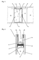
- a sliding door system is shown in front view.
- the formed in this embodiment as a sliding door leaf wing 1, which has two mutually parallel discs 2, 3, in particular glass, and at least partially arranged in the edge region 6 between the discs 2, 3 carrying and / or edge termination device is fixed to a fixed along a Building ceiling 7 arranged guide rail 8 via a guide device 9, which has two roller carriage 10 with rollers 11, slidably mounted.
- the closable by the wing 1 passage area 12 of the sliding door system is bounded laterally by building walls 13.
- One in the edge area of the wing 1 mounted handle device 15 is used for manual actuation of the wing 1.
- a power-operated displacement of the wing 1 by a drive device is conceivable.
- the wing 1 may also have a guide device, which can serve the bottom-side guide and / or locking, but not shown here.
- the wing 1 is, as can be seen in particular from the sectional view of Fig. 2 can be seen, formed as a so-called integrated all-glass wing and has two outer, designed as discs discs 2, 3, between which in the edge region 6 circumferentially a spacer 17 is arranged.
- the spacer 17 may in this case be formed in one piece and at the corners of the wing 1 each bent or -knuckled. Alternatively, the spacer 17 may be formed in several pieces, for example, per edge of the wing 1, a profile piece, wherein the profile pieces are connected to each other via corner joints.
- the spacer 17 may include in a receiving chamber 18 cooperating with the disc interior 19 air drying agent, to which the spacer 17 to the disc interior 19 has directed openings. Since the openings lie in other sectional planes, they are not shown in the drawings.
- the surface of the spacer 17 adjoining the free space 24 is circumferentially covered with a sealant 22, for example a potting compound, whereby the stability of the wing 1 and the hermetic seal are optimized.
- a sealant 22 for example a potting compound
- the edge element 16 which can be arranged in this free space 24 sections or completely encircling and is connected by an adhesive 20 with the inner sides of the discs 2, 3, is used for mounting fittings, seals or the like on the wing 1.
- the Edge element 16 is formed substantially U-shaped, wherein lateral profile legs, which are integrally connected by a profile base with each other, facing the outer edge of the wing 1.
- the two profile legs form with the profile base directed to the outer edge of the wing 1 receiving space 21 for attachment of the aforementioned fittings, seals or the like.
- the receiving space 21 is formed as an undercut groove in that the lateral profile limbs of the edge element 16 projections, in particular webs may have, and thus allows the fixation of said components, for example by with the projections verklemmbare nuts.
- the disks 2, 3 can at least in the edge region 6 covering the spacers 17 and the edge element 16 comprise a measure covering these elements, e.g. Printing, coating, surface treatment or the like.
- the edge element 16 may be formed of a glass fiber reinforced plastic (GRP).
- GRP glass fiber reinforced plastic
- the approximately equal length expansion of the disks 2, 3 and of the edge element 16 formed of fiberglass has an advantageous effect on the fatigue strength of the wing 1.
- the profiles of the edge element 16 may alternatively be formed of other suitable materials.
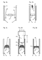
- the spacer 17 is preparatory to its the inner surfaces 4, 5 of the discs 2, 3 faces facing with sealant 23 (arrow A) and the discs 2, 3 then with the in the desired position (distance of the spacer 17 to the outer edge of the Au Shen 2, 3) pressed spacer 17 is pressed.
- the spacer 17 can also be connected in a sealing manner to the discs 2, 3 in some other way without additional sealant 22, e.g. by hot-pressing a self-sealing and adhesive spacer 23 with the disks 2, 3.
- the edges of the discs 2, 3 are masked by adhesive tape in order to protect them in the further manufacturing steps from damage and contamination.
- a sealant 22 is introduced into the free space 24 defined by the outer surface of the circumferential spacer 17 and the adjacent inner surfaces of the disks 2, 3 (arrow C).
- the sealant 22 is injected, for example by means of a nozzle in the free space 24, that the outer surface of the circumferential spacer 17 is completely covered by the sealant 24. It will be the in Fig. 3c achieved intermediate state achieved.
- the width B of the tool 25 is slightly smaller than the distance of the inner surfaces 4, 5 of the discs 2, 3, so that the tool 25 can be moved without jamming in the free space 24.
- the immersion depth T of the tool 25 is defined by supports, which rest on the outer edges of the discs 2, 3 and slide along.
- the leading edge of the tool 25 dips into the previously introduced mass of the sealant 22, so that by moving along the tool 25 along the outer edge of the wafer, the sealant 22 is leveled to a certain height defined by the tool 25. Excess sealant 22 is scraped off the tool 25 as needed.
- the sealant 22 is no longer bead-shaped, but with a relatively flat surface 26, ie it is the in Fig. 3e achieved intermediate state achieved.
- edge element 16 can be mounted on the wing 1.
- the cross-sectionally substantially U-shaped edge element 16 has below its profile base two C-shaped projections 32, which form a T-slot 27 with the profile base.
- web-shaped projections 30 are integrally formed on the outer sides of the lateral profile legs.
- the projections 32 of the profile base protrude beyond the outer surfaces of the lateral profile legs, so that correspondingly between or adjacent to the projections 30, 32 corresponding constrictions 29, 31 are present.
- web-shaped projections contact surfaces 28 are present.
- an assembly auxiliary tool 33 is connected to the edge element 16 (arrow E in FIG Fig. 3f ).
- the auxiliary assembly tool 33 is formed in cross-section substantially T-shaped and has two support legs 34 and a cylindrical shaft 35, at the lower edge there are two circular-segment-shaped contact surfaces 36.
- the width of the auxiliary assembly tool 33 is defined by the distance between two parallel flats 37 and is slightly smaller than the clear width of the receiving space 21 of the edge element 16. If the flats 37 are held at least approximately parallel to the longitudinal axis of the edge element 16, the auxiliary assembly tool 33 in introduce the receiving space 21 of the edge element 16.
- the auxiliary assembly tool 33 is rotated by 90 ° (arrow F in Fig. 3g ). Since the circular segment-shaped contact surfaces 36 have the same diametrical distance as the distance of corresponding contact surfaces 28 of the edge element 16, the contact surfaces 36 of the auxiliary assembly tool 33 come into contact with the contact surfaces 28 of the edge element 16. The support legs 34 of the auxiliary assembly tool 33 now overlap the upper edges of the lateral profile limbs of the edge element 16 and protrude beyond this ( Fig. 3h ). In this way, at least two assembly auxiliary tools 33 are placed per profile piece of the edge element 16.
- the arranged on the individual edges of the wing 1 edge elements 16 may each have a small gap at the joints of the corners, which serves for ventilation and drainage of the boundary elements 16 defined by the edge compound.
- an adhesive 20 an additional bonding between the edge element 16 and the inner surfaces 4, 5 of the discs 2, 3 introduced and thereby achieves additional bonding.
- a different section plane is shown than in Fig. 3 j because the assembly tools 33 are still mounted on the rim member 16. It is justifiable to omit the areas in which the assembly tools 33 are mounted from the adhesive 20, since these short breaks in the bond do not affect the stability of the anchoring of the marginal element 16.
- the adhesive 20, which may for example consist of the same material as the sealant 22, is preferably introduced by means of a flat nozzle into the constrictions 29 present between the inner surfaces 4, 5 of the disks 2, 3 and the lateral profile limbs of the edge element 16 (arrows H). such that after curing of the adhesive 20, removal of the auxiliary tools 33 and, if necessary, cutting off excess material of the adhesive 20 in the Fig. 2 already shown, finished state of the wing 1 is achieved. Now also the adhesive tape (not shown here) can be removed from the edges of the disks 2, 3.
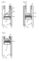
- FIG. 4 Another, opposite Fig. 2 modified embodiment of a wing 1 according to the invention is in the Fig. 4 shown.
- the profile base of the edge element 16 is arranged with its T-groove 27 spaced from the surface 26 of the sealant 22, whereby an optimal separation of the sealant 22 from the edge element 16, in particular of its adhesive 20 is achieved. This may be necessary in particular if the adhesive 20 of the edge element 16 is made of a different material than the sealant 22 and these two materials would undesirably react with each other.
- the bond is formed from an adhesive 38 deviating from the sealant 22, for example from a high-strength two-component structural adhesive.
- the edge element 16 spaced from the material of the sealant 22 may be arranged, as in the embodiment according to Fig. 4 is shown.
- FIG. 6 Another, opposite the Fig. 2 . 4 and 5 modified embodiment is in the Fig. 6 shown.
- the edge element 16 is formed with shorter side profile legs.
- the edge element 16 spaced from the material of the sealant 22 may be arranged, as in the embodiment according to Fig. 4 is shown, and / or alternatively, instead of the sealing material formed with the material 22 of the bonding therefrom a different adhesive 38 may be used, as in the embodiment according to FIG Fig. 5 is shown.
- the outer bonding may optionally even be dispensed with if the edge element 16, which is already fixed by the sealant 22 in the space 24 between the discs 2, 3, does not have to transmit high forces.
Landscapes
- Engineering & Computer Science (AREA)
- Civil Engineering (AREA)
- Structural Engineering (AREA)
- Securing Of Glass Panes Or The Like (AREA)
Applications Claiming Priority (1)
| Application Number | Priority Date | Filing Date | Title |
|---|---|---|---|
| DE102011002676A DE102011002676A1 (de) | 2011-01-14 | 2011-01-14 | Flügel einer Tür, eines Fensters oder dergleiche, sowie Verfahren zur Herstellung eines Flügels einer Tür, eines Fensters oder dergleichen |
Publications (1)
| Publication Number | Publication Date |
|---|---|
| EP2476851A2 true EP2476851A2 (fr) | 2012-07-18 |
Family
ID=45470445
Family Applications (1)
| Application Number | Title | Priority Date | Filing Date |
|---|---|---|---|
| EP12150856A Withdrawn EP2476851A2 (fr) | 2011-01-14 | 2012-01-12 | Battant de porte, de fenêtre ou analogue et procédé de fabrication d'un battant de porte, de fenêtre ou analogue |
Country Status (2)
| Country | Link |
|---|---|
| EP (1) | EP2476851A2 (fr) |
| DE (1) | DE102011002676A1 (fr) |
Cited By (2)
| Publication number | Priority date | Publication date | Assignee | Title |
|---|---|---|---|---|
| EP3192960A1 (fr) * | 2016-01-12 | 2017-07-19 | AGC Glass Europe | Unité de verre isolant et procédés de production associés |
| EP3192959A1 (fr) * | 2016-01-12 | 2017-07-19 | AGC Glass Europe | Procédé pour produire des unités de verre isolant et unité de vere isolant |
Citations (1)
| Publication number | Priority date | Publication date | Assignee | Title |
|---|---|---|---|---|
| DE19634389C2 (de) | 1996-08-26 | 2000-12-21 | Dorma Gmbh & Co Kg | Ortsveränderbare Schiebewand |
-
2011
- 2011-01-14 DE DE102011002676A patent/DE102011002676A1/de not_active Withdrawn
-
2012
- 2012-01-12 EP EP12150856A patent/EP2476851A2/fr not_active Withdrawn
Patent Citations (1)
| Publication number | Priority date | Publication date | Assignee | Title |
|---|---|---|---|---|
| DE19634389C2 (de) | 1996-08-26 | 2000-12-21 | Dorma Gmbh & Co Kg | Ortsveränderbare Schiebewand |
Cited By (5)
| Publication number | Priority date | Publication date | Assignee | Title |
|---|---|---|---|---|
| EP3192960A1 (fr) * | 2016-01-12 | 2017-07-19 | AGC Glass Europe | Unité de verre isolant et procédés de production associés |
| EP3192959A1 (fr) * | 2016-01-12 | 2017-07-19 | AGC Glass Europe | Procédé pour produire des unités de verre isolant et unité de vere isolant |
| WO2017121600A1 (fr) * | 2016-01-12 | 2017-07-20 | Agc Glass Europe | Unité de vitrage isolant et procédés de production associés |
| WO2017121601A1 (fr) * | 2016-01-12 | 2017-07-20 | Agc Glass Europe | Procédé de production d'unités de verre d'isolation |
| EA034905B1 (ru) * | 2016-01-12 | 2020-04-03 | Агк Гласс Юроп | Способ изготовления стеклопакета и стеклопакет |
Also Published As
| Publication number | Publication date |
|---|---|
| DE102011002676A1 (de) | 2012-07-19 |
Similar Documents
| Publication | Publication Date | Title |
|---|---|---|
| DE2808916C2 (fr) | ||
| EP2476852B1 (fr) | Dispositif d'aide au montage pour un battant de porte, de fenêtre ou analogue | |
| EP0029984A1 (fr) | Verre laminé isolant et procédé pour sa fabrication | |
| DE2648295A1 (de) | Verglasung, verfahren zum werksseitigen verglasen von glasscheiben sowie vorrichtung zur durchfuehrung des verfahrens | |
| EP2508377A2 (fr) | Unité de vitre avec un joint d'étanchéité pour fenêtre de véhicules automobiles | |
| WO2014154207A1 (fr) | Agencement structural et procédé pour fixer un échafaudage sur un mur de bâtiment | |
| EP4092240A1 (fr) | Nouvelle technique de collage destinée à la pose de fenêtres | |
| WO2022078660A1 (fr) | Système, comprenant un élément profilé de seuil, un élément profilé de cadre et un raccord de seuil, d'une fenêtre ou d'une porte | |
| EP0825052B1 (fr) | Dispositif de fixation d'une vitre dans un véhicule à moteur | |
| DE202015106983U1 (de) | System zur schraubenlosen Fixierung einer Glasscheibe | |
| EP2476851A2 (fr) | Battant de porte, de fenêtre ou analogue et procédé de fabrication d'un battant de porte, de fenêtre ou analogue | |
| WO2016162154A1 (fr) | Procédé de fabrication de blocs-fenêtres | |
| EP1946951B1 (fr) | Procédé destiné à la fabrication d'un joint, en particulier pour un véhicule automobile, et un tel joint | |
| EP3625100B1 (fr) | Cadre auxiliaire destiné à être inséré dans un cadre de fenêtre relié à demeure à une paroi extérieure, véhicule ferroviaire equipé d'un systeme de fenêtre | |
| EP2405093B1 (fr) | Verrière ignifuge modulaire | |
| DE202016101243U1 (de) | Glasklemmhalter | |
| DE10106433A1 (de) | Verfahren zur Herstellung eines Fahrzeuges und ein nach diesem Verfahren hergestelltes Fahrzeug | |
| DE102006054427B4 (de) | Alu-Kunststoff-Fenster mit Klebebandfixierung | |
| DE19809537A1 (de) | Verfahren zum Herstellen eines auf einer Unterlage angeordneten Befestigungselementes, insbesondere eines Fußbauteils für eine Aufklippbefestigungsanordnung | |
| EP3064699B1 (fr) | Fenêtre ou porte et leur procédé de fabrication | |
| EP0110295A2 (fr) | Cadre d'espacement pour vitrage isolant dont les bords sont collés | |
| DE2420620C2 (de) | Verfahren zum Abdichten von Fugen, insbesondere an Bauwerksteilen, Verglasungen u.dgl. sowie Dichtstoffprofilleiste zu seiner Durchführung | |
| WO2006027082A1 (fr) | Ensemble d'elements comprenant au moins un meneau et au moins deux pieces d'extremite de meneau a integrer dans une vitre isolante | |
| DE10111859A1 (de) | Verfahren zum Verbinden von Glasteilen mit anderen Glasteilen oder mit Abdicht- oder Verbindungsprofilen und entsprechende Verbindung | |
| EP3309342A1 (fr) | Procédé de production de calages de fenêtres et dispositif d'application |
Legal Events
| Date | Code | Title | Description |
|---|---|---|---|
| PUAI | Public reference made under article 153(3) epc to a published international application that has entered the european phase |
Free format text: ORIGINAL CODE: 0009012 |
|
| AK | Designated contracting states |
Kind code of ref document: A2 Designated state(s): AL AT BE BG CH CY CZ DE DK EE ES FI FR GB GR HR HU IE IS IT LI LT LU LV MC MK MT NL NO PL PT RO RS SE SI SK SM TR |
|
| AX | Request for extension of the european patent |
Extension state: BA ME |
|
| STAA | Information on the status of an ep patent application or granted ep patent |
Free format text: STATUS: THE APPLICATION HAS BEEN WITHDRAWN |
|
| 18W | Application withdrawn |
Effective date: 20140110 |