EP2476908B1 - Ventilateur tangentiel, filière de moulage et dispositif d'apport de fluide - Google Patents
Ventilateur tangentiel, filière de moulage et dispositif d'apport de fluide Download PDFInfo
- Publication number
- EP2476908B1 EP2476908B1 EP10815346.1A EP10815346A EP2476908B1 EP 2476908 B1 EP2476908 B1 EP 2476908B1 EP 10815346 A EP10815346 A EP 10815346A EP 2476908 B1 EP2476908 B1 EP 2476908B1
- Authority
- EP
- European Patent Office
- Prior art keywords
- cross
- blades
- fan
- flow fan
- blade
- Prior art date
- Legal status (The legal status is an assumption and is not a legal conclusion. Google has not performed a legal analysis and makes no representation as to the accuracy of the status listed.)
- Not-in-force
Links
Images




Classifications
-
- F—MECHANICAL ENGINEERING; LIGHTING; HEATING; WEAPONS; BLASTING
- F04—POSITIVE - DISPLACEMENT MACHINES FOR LIQUIDS; PUMPS FOR LIQUIDS OR ELASTIC FLUIDS
- F04D—NON-POSITIVE-DISPLACEMENT PUMPS
- F04D29/00—Details, component parts, or accessories
- F04D29/66—Combating cavitation, whirls, noise, vibration or the like; Balancing
-
- F—MECHANICAL ENGINEERING; LIGHTING; HEATING; WEAPONS; BLASTING
- F04—POSITIVE - DISPLACEMENT MACHINES FOR LIQUIDS; PUMPS FOR LIQUIDS OR ELASTIC FLUIDS
- F04D—NON-POSITIVE-DISPLACEMENT PUMPS
- F04D29/00—Details, component parts, or accessories
- F04D29/26—Rotors specially for elastic fluids
- F04D29/28—Rotors specially for elastic fluids for centrifugal or helico-centrifugal pumps for radial-flow or helico-centrifugal pumps
- F04D29/281—Rotors specially for elastic fluids for centrifugal or helico-centrifugal pumps for radial-flow or helico-centrifugal pumps for fans or blowers
- F04D29/282—Rotors specially for elastic fluids for centrifugal or helico-centrifugal pumps for radial-flow or helico-centrifugal pumps for fans or blowers the leading edge of each vane being substantially parallel to the rotation axis
- F04D29/283—Rotors specially for elastic fluids for centrifugal or helico-centrifugal pumps for radial-flow or helico-centrifugal pumps for fans or blowers the leading edge of each vane being substantially parallel to the rotation axis rotors of the squirrel-cage type
-
- F—MECHANICAL ENGINEERING; LIGHTING; HEATING; WEAPONS; BLASTING
- F04—POSITIVE - DISPLACEMENT MACHINES FOR LIQUIDS; PUMPS FOR LIQUIDS OR ELASTIC FLUIDS
- F04D—NON-POSITIVE-DISPLACEMENT PUMPS
- F04D17/00—Radial-flow pumps, e.g. centrifugal pumps; Helico-centrifugal pumps
- F04D17/02—Radial-flow pumps, e.g. centrifugal pumps; Helico-centrifugal pumps having non-centrifugal stages, e.g. centripetal
- F04D17/04—Radial-flow pumps, e.g. centrifugal pumps; Helico-centrifugal pumps having non-centrifugal stages, e.g. centripetal of transverse-flow type
-
- F—MECHANICAL ENGINEERING; LIGHTING; HEATING; WEAPONS; BLASTING
- F04—POSITIVE - DISPLACEMENT MACHINES FOR LIQUIDS; PUMPS FOR LIQUIDS OR ELASTIC FLUIDS
- F04D—NON-POSITIVE-DISPLACEMENT PUMPS
- F04D29/00—Details, component parts, or accessories
- F04D29/66—Combating cavitation, whirls, noise, vibration or the like; Balancing
- F04D29/661—Combating cavitation, whirls, noise, vibration or the like; Balancing especially adapted for elastic fluid pumps
- F04D29/663—Sound attenuation
- F04D29/665—Sound attenuation by means of resonance chambers or interference
-
- F—MECHANICAL ENGINEERING; LIGHTING; HEATING; WEAPONS; BLASTING
- F04—POSITIVE - DISPLACEMENT MACHINES FOR LIQUIDS; PUMPS FOR LIQUIDS OR ELASTIC FLUIDS
- F04D—NON-POSITIVE-DISPLACEMENT PUMPS
- F04D29/00—Details, component parts, or accessories
- F04D29/66—Combating cavitation, whirls, noise, vibration or the like; Balancing
- F04D29/661—Combating cavitation, whirls, noise, vibration or the like; Balancing especially adapted for elastic fluid pumps
- F04D29/666—Combating cavitation, whirls, noise, vibration or the like; Balancing especially adapted for elastic fluid pumps by means of rotor construction or layout, e.g. unequal distribution of blades or vanes
Definitions
- the present invention generally relates to a cross-flow fan, a molding die, and a fluid feeder, more particularly to a cross-flow fan, a molding die used to produce the cross-flow fan, and a fluid feeder equipped with the cross-flow fan, for example, air conditioner, air purifier, humidifier, dehumidifier, electric fan, fan heater, cooling device, or ventilating device.
- a cross-flow fan for example, air conditioner, air purifier, humidifier, dehumidifier, electric fan, fan heater, cooling device, or ventilating device.
- Japanese Patent Laying-Open No. 2006-118496 discloses a conventional cross-flow fan designed with an attempt to reduce noises caused by fluid oscillation and to improve an air-blow performance (PTL 1).
- the cross-flow fan disclosed in PTL 1 is provided with at least 34 blades to at most 36 blades.
- the blades respectively have random pitches (angles), and the following relationship is met; 1.0 (deg) ⁇ Pmax-Pmin ⁇ 2.5 (deg), where Pmax is the largest pitch and Pmin is the smallest pitch.
- Japanese Patent Laying-Open No. 2003-269363 discloses a tangential fan blade wheel designed with an attempt to effectively reduce discrete frequency noises (PTL 2).
- PTL 2 discrete frequency noises
- the tangential fan blade wheel disclosed in PTL 2 plural blades are divided into even-numbered groups having an equal number of blades.
- the tangential fan blade wheel is structurally characterized in that respective blocks of the blade wheel are axially displaced by an angle ⁇ and joined with one another to minimize the synthesized sound pressure of an NZr component wave in each block.
- the conventional cross-flow fans so far disclosed which are used in, for example, air conditioners and air purifiers, are variously devised to reduce noises and achieve a higher operating efficiency.
- these fans were invented to provide solutions for any abnormal sounds auditorily offensive, for example, short-wavelength noises, generally called blade passing sounds (whistling sounds) and noises generated when an inter-blade airflow is disturbed (generally called surging sounds).
- the cross-flow fan disclosed in PTL 1 is designed with an attempt to control the occurrence of any abnormal sounds by devising blade installation pitches in the direction of rotation of the fan.
- the tangential fan blade wheel disclosed in PTL 2 is designed with an attempt to control the occurrence of any abnormal sounds by devising the arrangement of blades in the direction of rotation of the fan and the displacement angle between blocks of the blade wheel.
- the cross-flow fan When a cross-flow fan configured to blow air with a higher air flow rate is desirably obtained, the cross-flow fan needs to be formed in a larger diameter.
- a ratio between inner and outer diameters of the fan must stay within a required numeral range because the lengths of blades are subject to certain restrictions to avoid deterioration of an air-blowing efficiency.
- Another requirement for preventing the air-blowing efficiency from deteriorating is that a ratio between the blade length and inter-blade interval must stay within a required numeral range.
- the present invention was accomplished to overcome these conventional technical disadvantages.
- the present invention provides a cross-flow fan that can succeed in noise reduction, a molding die used to produce the cross-flow fan, and a fluid feeder equipped with the cross-flow fan.
- the displacement angle upon focusing on an arbitrary one of the blade wheels (for example, number j) and another one of the blade wheels adjacent thereto (for example, number j + 1), the displacement angle is defined as a predefined angle at which the blade wheel (j + 1) is displaced relative to the blade wheel (j) in the circumferential direction centered on the predefined axis from a position where all of the blades of the blade wheel (j) and the blade wheel (j + 1) are overlapping one another in the axial direction of the predefined axis.
- the blade having an installation angle around the predefined axis equal to angles of the other blades is identified in each of the N ⁇ M blades in total, and a total number of the identified blades is defined as the "overlapping number”.
- the overlapping number of the blades having an equal installation angle is at most 5% of the N ⁇ M blades in total, narrow-band noises resulting from the blade passing sounds (nZ sounds) can be effectively controlled. This succeeds in reducing noises generated by the rotation of the cross-flow fan.
- ( ⁇ D/N represents inter-blade intervals of the blades equally spaced around the predefined axis
- represents a degree of variability of the inter-blade intervals as compared to the structure where the blades are equally spaced around the predefined axis.
- the cross-flow fan preferably further meets the relationship expressed by 0.68 ⁇ d/D ⁇ 0.86.
- the cross-flow fan preferably further meets the relationship expressed by 1.4 ⁇ L/( ⁇ D/N) ⁇ 2.1.
- the cross-flow fan preferably further meets the relationship expressed by 0.43 ⁇ ⁇ D/N ⁇ M) ⁇ 2.83.
- the cross-flow fan thus structured can ensure a sufficiently high air-blow performance and effectively reduce noises generated by the rotation of the cross-flow fan.
- the present invention can provide a cross-flow fan that can succeed in noise reduction, a molding die used to produce the cross-flow fan, and a fluid feeder equipped with the cross-flow fan.
- the word 'embodiment' simply means 'example' and does not imply that the example is part of the invention.
- the use of the word 'aspect' to introduce (or to refer) some subject-matter does not imply that this subject-matter is part of the invention.
- the invention is defined by the appended claims only, therefore all the embodiments belonging to the invention have to respect simultaneously Formula 1, Formula 2, Formula 3 and Formula 4 explained here under.
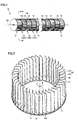
- Fig. 1 is a side view of a cross-flow fan according to an embodiment 1.
- Fig. 2 is a perspective view of the cross-flow fan along II-II line illustrated in Fig. 1 .
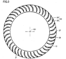
- Fig. 3 is a sectional view of the cross-flow fan along II-II line illustrated in Fig. 1 .
- a cross-flow fan 10 is structured such that a plurality of blade wheels 12 stacked on one another in an axial direction of a center axis 101 are combined.
- Blade wheels 12 each has a plurality of fan blades 21 and an outer peripheral frame 13.
- Plural fan blades 21 are spaced from one another at intervals in a circumferential direction centered on virtual center axis 101.
- the overall external appearance of cross-flow fan 10 is a substantially cylindrical shape, and plural fan blades 21 are arranged on a side surface of the substantially cylindrical shape.
- Cross-flow fan 10 is produced from resin in an integral structure.
- Cross-flow fan 10 is rotated in a direction illustrated in Fig. 2 with an arrow 103 around center axis 101 as a rotational center.
- Cross-flow fan 10 sends air in a direction orthogonal to center axis 101 by rotating plural fan blades 21. Observing the operation of cross-flow fan 10 from an axial direction of center axis 101, air is sucked from an external space on one side relative to center axis 101 into an internal space of the fan and then blown out into an external space on the other side relative to center axis 101.
- Cross-flow fan 10 forms an airflow travelling in a direction intersecting with center axis 101 in a plane orthogonal to center axis 101.
- Cross-flow fan 10 forms a flat flow of the blown-out air in parallel with center axis 101.
- Cross-flow fan 10 is used at the number of rotations in the range of low Reynolds numbers applied to fans such as home-use electric devices.
- Outer peripheral frame 13 has a ring shape centered on center axis 101 and extending in an annular shape. Outer peripheral frame 13 has an end surface 13a and an end surface 13b. End surface 13a is formed in a direction along the axial direction of center axis 101. End surface 13b is formed on the back side of end surface 13a in the other direction along the axial direction of center axis 101.
- Outer peripheral frame 13 is interposed between adjacent blade wheels 12 in the axial direction of center axis 101.
- plural fan blades 21 provided in blade wheel 12A are connected to end surface 13a and formed so as to extend in a plate-like shape along the axial direction of center axis 101, while plural fan blades 21 provided in blade wheel 12B are connected to end surface 13b and formed so as to extend in a plate-like shape along the axial direction of center axis 101.
- each of fan blades 21 has an inner peripheral portion 26 and an outer peripheral portion 27.
- Inner peripheral portion 26 is provided on the inner peripheral side of fan blade 21.
- Outer peripheral portion 27 is provided on the outer peripheral side of fan blade 21.
- Fan blade 21 is formed with a tilt in the circumferential direction centered on center axis 101 from inner peripheral portion 26 toward outer peripheral portion 27 thereof.
- Fan blade 21 is also formed with a tilt in the direction of rotation of cross-flow fan 10 from inner peripheral portion 26 toward outer peripheral portion 27 thereof.
- Fan blades 21 each has a blade surface 23 including a positive pressure surface 24 and a negative pressure surface 25.
- Positive pressure surface 24 is formed on the side of the direction of rotation of cross-flow fan 10
- negative pressure surface 25 is formed on the back side of positive pressure surface 24.
- Fan blade 21 has an overall shape curved between inner peripheral portion 26 and outer peripheral portion 27 where the side of positive pressure surface 24 is has a concave shape and the side of negative pressure surface 25 has a convex shape.
- Fan blades 21 are formed in a manner that shapes thereof in cross section are all equal even when cut across at any position in the axial direction of center axis 101, and the shapes in cross section thereof have a small thickness. Further, fan blades 21 are each formed in a substantially equal thickness (a length between positive pressure surface 24 and negative pressure surface 25) between inner peripheral portion 26 and outer peripheral portion 27.
- Plural fan blades 21 are arranged at random pitches in the circumferential direction centered on center axis 101.
- the random pitches are obtained by locating plural fan blades 21 at unequal intervals in accordance with random-number normal distribution.
- Plural blade wheels 12 are formed in a manner that fan blades 21 are all uniformly arranged. More specifically describing the arrangement, intervals between plural fan blades 21 and the order of fan blades 21 arranged with the intervals therebetween are all uniform in all of blade wheels 12.
- N represents the number of fan blades 21 provided in each blade wheel 12
- M represents the number of blade wheels 12 stacked on one another in the axial direction of center axis 101.
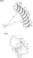
- Fig. 4 is an enlarged sectional view of a part of the cross-flow fan illustrated in Fig. 3 .
- Fig. 5 is a sectional view of a fan blade of the cross-flow fan illustrated in Fig. 3 .
- Fig. 4 illustrates an inscribed circle 310 centered on center axis 101 and inscribing plural fan blades 21 arranged in the circumferential direction, and a circumscribed circle 315 centered on center axis 101 and circumscribing plural fan blades 21 arranged in the circumferential direction.
- Cross-flow fan 10 according to the present embodiment is formed such that fan blades 21 have an inner diameter d represented by the diameter of inscribed circle 310 and an outer diameter D represented by the diameter of circumscribed circle 315.
- a circular arc centered on center axis 101 and connecting outer peripheral ends of adjacent fan blades 21 has a length Cn. More specifically, the length Cn represents a length of the circular arc of circumscribed circle 315 between a point of contact of fan blade 21 with circumscribed circle 315 and a point of contact of another fan blade 21 with circumscribed circle 315 and adjacent to fan blade 21, wherein n takes values 1, 2, ..., N-1, N (number of fan blades 21), and Cn represents a circular arc length at each position between adjacent fan blades 21.
- Fig. 5 illustrates a straight line 106 contacting an end portion of inner peripheral portion 26 and an end portion of outer peripheral portion 27 of fan blade 21 on the side of positive pressure surface 24, and a straight line 107 contacting blade surface 23 of fan blade 21 on the side of negative pressure surface 25, and extending in parallel with straight line 106, a straight line 109 contacting outer peripheral portion 27 of fan blade 21 and perpendicular to straight line 106 and straight line 107, and a straight line 108 contacting inner peripheral portion 26 of fan blade 21 and perpendicular to straight line 106 and straight line 107.
- a chord length of fan blade 21 is represented by a length L of straight line 106 between straight line 109 and straight line 108.
- Cross-flow fan 10 is configured to meet the relationships expressed by the following Formulas 1 to 3 in relation to inner diameter d and outer diameter D of fan blade 21, N representing the number of fan blades 21, M representing the number of blade wheels 12, and chord length L of fan blade 21.
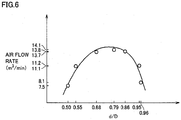
- d/D has a value approximately 0.79.
- inner diameter d is too small for the dimension of outer diameter D of fan blade 21, failing to constantly generate forced vortex which is the source of an airflow crossing through the fan (airflow traversing center axis 101) which is a particularly unique feature of any cross-flow fans. This undermines the air-blow performance of fan blades 21, thereby failing to accomplish an adequate air-blow performance expected in any cross-flow fans.
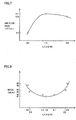
- the value of d/D is larger than 0.95, although there is constantly forced vortex, inner diameter d is too large for the dimension of outer diameter D of fan blade 21, and it is no longer possible to have an enough chord length of fan blade 21. This undermines the dynamic lift of fan blades 21 necessary for blast, thereby failing to accomplish an adequate air-blow performance expected in any cross-flow fans.
- cross-flow fan 10 in which the ratio d/D between inner diameter d and outer diameter D of fan blade 21 stays within the range 0.55 ⁇ d/D ⁇ 0.95, can accomplish an adequate air-blow performance as the cross-flow fans.
- This example prepared a plurality of cross-flow fans respectively having different d/D values.
- the cross-flow fans were each mounted in an air blower equipped in the indoor unit of a room air conditioner to measure air flow rates at the number of rotations 1,200 rpm based on JISB8615-1.
- cross-flow fan 10 according to the present embodiment can reliably accomplish an adequate air-blow performance expected as the cross-flow fans.
- L/( ⁇ D/N) is approximately 1.6.
- the value of ( ⁇ D/N) defined by outer diameter D of fan blades 21 and N representing the number of fan blades 21 in the circumferential direction is a circular arc length between adjacent fan blades 21 if fan blades 21 are spaced at equal intervals, and the value serves as a reference value of a real interval between adjacent fan blades 21.
- the ratio between chord length L and the arc length indicating the real interval, L/( ⁇ D/N), is equivalent to an aspect ratio of flow paths between fan blades 21 when viewed from a rotational axis direction of the fan (axial direction of center axis 101), and the ratio serves as a reference value of the impact magnitude of flow resistances received from blade surfaces 23 when the airflow passes through the flow paths between fan blades 21.
- N representing the number of fan blades 21 has large values when the value of L/( ⁇ D/N) is larger than 2.8.
- N representing the number of fan blades 21 is larger, the arrangement of fan blades 21 in the circumferential direction is less random. As a result, narrow-band noises resulting from blade passing sounds (nZ sounds) are much louder.
- cross-flow fan 10 is configured to meet the relationship expressed by 0.6 ⁇ L/( ⁇ D/N) ⁇ 2.8.
- the cross-flow fan thus configured can accomplish an expected air-blow performance and also effectively reduce narrow-band noises resulting from the blade passing sounds.
- cross-flow fan 10 can more effectively accomplish the above effects.
- the cross-flow fans thus prepared were each mounted in an air blower equipped in the indoor unit of a room air conditioner to measure air flow rates and noises. The air flow rates were measured based on JISB8615-1, and the noises were measured based on JISC9612.
- the air flow rate measured at the same number of rotations, 1,200 rpm was approximately 4.2 m 3 /min.
- the air flow rate measured at the number of rotations of 2,000 rpm was approximately 7.0 m 3 /min.
- the comparative example fails to accomplish an expected air-blow performance. Note that in order to more increase the number of rotations, it is necessary to take additional measures for strength enhancement such as using metals as the material of fan blades 21 to be strong enough against a centrifugal force, so that the comparative example is not preferable.
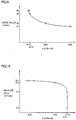
- Fig. 8 is a graph illustrating a relationship between L/( ⁇ D/N) and noise values according to the example 2.
- the noise value when the same air flow rate of 10 m 3 /min was obtained was approximately 48 dB (A). Particularly, broad-band noises significantly increased, thus exhibiting adverse impacts resulting from large-scale separation between adjacent fan blades 21.
- the noise value when the same air flow rate of 10 m 3 /min was obtained was approximately 49 dB (A), thus exhibiting adverse impacts resulting from the significantly increased narrow-band noises.
- cross-flow fan 10 according to the present embodiment meeting the relationship of Formula 2 succeeds in improving the air-blow performance and reducing the narrow-band noises caused by the blade passing sounds.
- the value of ⁇ D/(N ⁇ M) defined by outer diameter D of fan blades 21, N representing the number of fan blades 21, and M representing the number of blade wheels 12 is a value used as a reference value for estimating the likelihood of overlap between fan blades 21 at circumferential positions on the outer diameter in different blade wheels 12 when cross sectional surfaces of all of fan blades 21 provided in the fan are projected on a plane orthogonal to center axis 101.
- N representing the number of fan blades 21 is too small, possibly overly widening the intervals between adjacent fan blades 21 as described earlier, or failing to ensure a fan length in the axial direction of center axis 101 long enough to constantly generate forced vortex which is the source of the airflow crossing through the fan because of M representing the number of blade wheels 12 is too small.
- M representing the number of blade wheels 12 is too small.
- the occurrence of these unfavorable events undermines the air-blow performance of fan blades 21. As a result, an adequate air-blow performance expected in any cross-flow fans cannot be accomplished.
- cross-flow fan 10 according to the present embodiment meeting the relationship expressed by 0.15 ⁇ ⁇ D/N ⁇ M) ⁇ 3.77 can ensure an adequate air-blow performance expected in any cross-flow fans. More particularly, cross-flow fan 10 can avoid any greatly adverse impacts caused by narrow-band noises resulting from too many fan blades 21 or too many overlapping fan blades 21 at circumferential positions on the outer diameter in the different blade wheels.
- cross-flow fan 10 meets the relationship expressed by 0.43 ⁇ ⁇ D(N ⁇ M) ⁇ 2.83.
- significant deterioration of the air-blow performance caused by too small N representing the number of fan blades 21 and too small M representing the number of blade wheels 12 can be prevented.
- an adequate air-blow performance expected as the cross-flow fans can be adequately accomplished.
- M representing the number of blade wheels 12 changes, and a suitable numeral range of ⁇ D/(N ⁇ M) accordingly changes.
- the value of ⁇ D/(N ⁇ M) preferably stays within the numeral range of 0.43 ⁇ ⁇ D(N ⁇ M) ⁇ 1.68 when cross-flow fan 10 is used in electric devices where M representing the number of blade wheels 12 is relatively large (M ⁇ 5) such as air conditioner, electric fan, and ventilating device.
- ⁇ D/(N ⁇ M) more suitably stays within the numeral range of 1.34 ⁇ ⁇ D(N ⁇ M) ⁇ 2.83 when cross-flow fan 10 is used in electric devices where M representing the number of blade wheels 12 is relatively small (M ⁇ 6) such as air purifier, humidifier, and dehumidifier.
- the cross-flow fans thus prepared were each mounted in an air blower equipped in the indoor unit of a room air conditioner to measure air flow rates and noises. The air flow rates were measured based on JISB8615-1, and the noises were measured based on JISC9612.
- Fig. 9 is a graph illustrating a relationship between ⁇ D/(N ⁇ M) and noise values according to the example 3.
- the cross-flow fan for comparison showed increases of; not more than approximately 9 dB (A) in a noise level at blade passing frequencies, and not more than approximately 5 dB (A) in an overall noise value.
- Fig. 10 is a graph illustrating a relationship between ⁇ D/(N ⁇ M) and air flow rates according to the example 3.
- cross-flow fan 10 according to the present embodiment meeting the relationship expressed by Formula 3 can ensure an adequate air-blow performance of the cross-flow fans and avoid any greatly adverse impacts caused by narrow-band noises.
- ( ⁇ D/N) represents intervals between fan blades 21 when fan blades 21 are equally spaced around center axis 101.
- represents a degree of variability of intervals between fan blades 21 as compared to the arrangement of fan blades 21 equally spaced around center axis 101.
- is smaller than 5% of ( ⁇ D/N)
- fan blades 21 are almost equally spaced, involving the risk of considerably increasing the blade passing sounds.
- is larger than 24% of ( ⁇ D/N)
- some of fan blades 21 are too distantly spaced from each other around center axis 101, involving the risk of large separation sounds at the overly large intervals.
- cross-flow fan 10 according to the present embodiment meeting the relationship expressed by 0.05( ⁇ D/N) ⁇
- This example prepared a plurality of cross-flow fans having different ratios between
- the cross-flow fans were each mounted in an air blower equipped in the indoor unit of a room air conditioner to measure noise values when the air flow rate of 10 m 3 /min is obtained.
- the noise values were measured based on JISC9612.
- the noise values obtained in the cross-flow fans meeting the relationship of Formula 4 were, respectively; approximately 43dB (A) (Min
- cross-flow fan 10 according to the present embodiment meeting the relationship of Formula 4 can effectively control the occurrence of the passing sounds and/or separation sounds of fan blades 21.
- Cross-flow fan 10 is formed such that plural blade wheels 12 are stacked on one another in a manner that a displacement angle ⁇ is generated between adjacent blade wheels 12 when viewed from the axial direction of center axis 101.
- Blade wheel 12B is stacked on blade wheel 12A in a manner that all of fan blades 21 in blade wheels 12A and 12B both are displaced in the circumferential direction of center axis 101 by displacement angle ⁇ from positions where these fan blades 21 overlap in the axial direction of center axis 101.
- Blade wheel 12C is stacked on blade wheel 12B in a manner that all of fan blades 21 in blade wheels 12C and 12B both are displaced in the circumferential direction of center axis 101 by displacement angle ⁇ (2 ⁇ when viewed from the side of blade wheel 12A) from positions where these fan blades 21 overlap in the axial direction of center axis 101.
- the positions of fan blades 21 in different wheel blades 12 are intentionally displaced in the axial direction of center axis 101, so that the blade passing sounds (nZ sounds) generated in the respective blade wheels 12 can counteract each other to be weakened.
- displacement angle ⁇ is set to stay within the range of (1.2 ⁇ 360°/(N ⁇ M)) ⁇ ⁇ ⁇ (360°/N), and the overlapping number of fan blades 21 having an equal installation angle is at most 5% of the N ⁇ M blades 21 in total.
- This structural feature can control the occurrence of narrow-band noises resulting from the blade passing sounds (nZ sounds) to such an extent that they are no longer auditorily disturbing noises in a structure where N representing the number of fan blades 21 is particularly large.
- the displacement angle is set to 0.1° based on a dimensional accuracy when a molding die for cross-flow fan 10 is produced.
- the value of the installation angle has digits that depend on a dimensional accuracy in molding cross-flow fan 10.
- the present embodiment sets the digits depending on the dimensional accuracy when the molding die for blade wheel 12 is produced, employing a numeral range to one place of decimals.
- the installation angles of fan blade 21 on one blade wheel 12 are respectively 0°, 9°, 18°, 27°, ..., 342°, and 351°. Because of the displacement angle being set to 0°, the installation angles of 40 fan blades 21 in any other blade wheels 12 are similarly set.
- the counted blades are all of fan blades 21 in other nine blade wheels 12 having the installation angle of 0°.
- the overlapping number of fan blades 21 at the installation angle 0° based on blade wheel 12 is nine.
- a counting result of the overlapping number for the other installation angles of blades 21 (9°, 18°, ...) is also nine.
- the overlapping number is similarly calculated in any other blade wheels 21.
- the overlapping number is way over 400 (40 ⁇ 10) fan blades 21 in total.
- all of fan blades 21 numerically contribute to the occurrence of the blade passing sounds (narrow-band noises), thereby exerting a significant influence.
- Studying overlapping number based on the total number of fan blades 21, an extent of contribution by the "overlapping number" to the blade passing sounds (narrow-band noises) can be easily estimated.
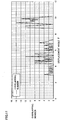
- Fig. 11 is a graph illustrating a relationship between displacement angles between adjacent blades and respective overlapping numbers of fan blades in the cross-flow fan according to the reference example.
- the installation angles of fan blades 21 in one blade wheel 12 were calculated according to the overlapping number calculation step recited in (4), and the installation angles of fan blades 21 in any other blade wheels 12 were calculated with the displacement angle taken into account, so that the installation angles of all of the fan blades 21 were obtained.
- a result thereby obtained indicated that the overlapping number is 0 at many displacement angles, and there is a region where the overlapping is continuously 0.
- the selection of the displacement angle is relatively easy as far as N representing the number of fan blades 21 and M representing the number of blade wheels 12 are both relatively small.
- displacement angle ⁇ is set to stay within the range of 1.05° ⁇ ⁇ ⁇ 8.78°, and the overlapping number of fan blades 21 having the same installation angles is at most 5% of 410 fan blades 21 in total, that is at most 20 fan blades 21.
- Fig. 12 is a graph illustrating a relationship between the displacement angles between adjacent blade wheels and the respective overlapping numbers of fan blades.
- the overlapping number is likely to increase in a structure where N representing the number of fan blades 21 and M representing the number of blade wheels 12 are both large.
- N representing the number of fan blades 21
- M representing the number of blade wheels 12 are both large.
- the present invention is more effectively applicable to any cross-flow fans having a structural shape where N>35 and M>4.
- the present invention is more suitably applicable to any cross-flow fans having a shape where N>40 and M>6 because the structural shape can significantly narrow a region where the overlapping number is small, thereby easily increasing the overlapping number of blades.
- the cross-flow fans respectively having different displacement angles were each mounted in an air blower equipped in the indoor unit of a room air conditioner to measure noise values, In this case, the measurement was performed based on JISC9612.
- Fig. 13 is a table reciting respective overlapping numbers of fan blades at different displacement angles, ratios of the overlapping numbers, and noise values.
- cross-flow fans where displacement angle ⁇ is 2.4°, 3.6°, 5.3°, 6.1°, and 7.2° represent the examples, while cross-flow fans where displacement angle ⁇ is 0.4°, 1.0°, 1.9°, 2.8°, and 5.9° represent the examples.
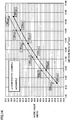
- Fig .14 is a graph illustrating a relationship between the air flow rates and the noise values in the cross-flow fans according to the comparative and examples.
- Fig. 15 is a graph illustrating a relationship between the air flow rates and frequencies in the cross-flow fans according to the comparative and examples.
- displacement angle ⁇ between adjacent blade wheels 12 is preferably equal to or larger than 1.2 ⁇ 360°/(N ⁇ M).
- displacement angle ⁇ of fan blades 21 is preferably equal to or smaller than 360°/N.
- the noise values of these cross-flow fans There are the following two factors for the noise values of these cross-flow fans.
- the overlapping number is 0 but the overlapping number is relatively large at near displacement angles (5.2°, 5.4°), suggesting that the actual displacement angle was shifted to one of these near displacement angles under the influences of a degree of accuracy during molding.
- the noise value can be set to a preferable noise level.
- an optimal value of the displacement angle may be assessed based on a center mean value of the overlapping number.
- the total number of fan blades 21 is 410 and the overlapping number is 38. Therefore, the overlapping number is approximately 9.2% of N ⁇ M representing the total number of fan blades 21.
- This embodiment describes a structure of an air conditioner in which cross-flow fan 10 illustrated in Fig. 1 is used.
- FIG. 16 is a sectional view of an air conditioner in which the cross-flow fan illustrated in Fig. 1 is used.
- an air conditioner 110 includes an indoor unit 120 placed inside a room and equipped with an indoor heat exchanger 129, and an outdoor unit, not illustrated in the drawings, placed outside the room and equipped with an outdoor heat exchanger and a compressor.
- Indoor unit 120 and the outdoor unit are connected to each other by a pipe arrangement to circulate a refrigerant gas between indoor heat exchanger 129 and the outdoor heat exchanger.
- Air blower 115 has a cross-flow fan 10, a drive motor, not illustrated in the drawings, which rotates cross-flow fan 10, and a casing 122 for generating a required airflow along with the rotation of cross-flow fan 10.
- Casing 122 has a cabinet 122A and a front panel 122B.
- Cabinet 122A is supported on a wall surface inside the room, and front panel 122B is detachably mounted in cabinet 122A.
- a blowout port 125 is formed in an interval between a lower end part of front panel 122B and a lower end part of cabinet 122A.
- Blowout port 125 is formed in a substantially rectangular shape extending in a width direction of indoor unit 120 and provided facing forward and downward.
- An upper surface of front panel 122B has an intake port 124 formed in a lattice shape.
- an air filter 128 is provided to catch and remove dust included in air sucked in through intake port 124.
- An air filter cleaning device is provided in a space formed between front panel 122B and air filter 128. The air filter cleaning device automatically removes dust accumulated in air filter 128.
- An air-blow passage 126 for the air to travel through from intake port 124 toward blowout port 125 is formed inside casing 122.
- Blowout port 125 is provided with a vertical louver 132 configured to direct a right-left blowout angle in right and left directions, and a plurality of lateral louvers 131 configured to direct an upper-lower blowout angle in forward and upward, horizontal, forward and downward, and downward directions.
- Indoor heat exchanger 129 is provided between cross-flow fan 10 and air filter 128 on the route of air-blow passage 126.
- Indoor heat exchanger 129 has winding refrigerant pipes, not illustrated in the drawings, arrayed in a plurality of stages in an upper - lower direction and a plurality of rows in a front-back direction in parallel with each other.
- Indoor heat exchanger 129 is connected to the compressor of the outdoor unit placed outside the room, and a refrigeration cycle is operated by a drive of the compressor. When the refrigeration cycle is operated, indoor heat exchanger 129 is cooled down to lower temperatures than ambient temperature during cooling operation, and indoor heat exchanger 129 is heated to higher temperatures than ambient temperature during heating operation.
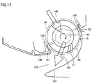
- Fig. 17 is an enlarged sectional view illustrating vicinity of the blowout port in the air conditioner illustrated in Fig. 16 .
- casing 122 has a front wall portion 151 and a rear wall portion 152. Front wall portion 151 and rear wall portion 152 are disposed facing each other with an interval therebetween.
- cross-flow fan 10 is situated between front wall portion 151 and rear wall portion 152.
- Front wall portion 151 has a projection 153 projecting toward an outer peripheral surface of cross-flow fan 10 to minimize a space between cross-flow fan 10 and front wall portion 151.
- Rear wall portion 152 has a projection 154 projecting toward the outer peripheral surface of cross-flow fan 10 to minimize a space between cross-flow fan 10 and rear wall portion 152.
- Casing 122 has an upper-side guiding portion 156 and a lower-side guiding portion 157.
- Air-blow passage 126 is regulated by upper-side guiding portion 156 and lower-side guiding portion 157 on the more downstream side of airflow than cross-flow fan 10.
- Upper-side guiding portion 156 and lower-side guiding portion 157 are respectively continuous from front wall portion 151 and rear wall portion 152 and extending toward blowout port 125. Upper-side guiding portion 156 and lower-side guiding portion 157 are curved in a manner that upper-side guiding portion 156 is on the inner peripheral side and lower-side guiding portion 157 is on the outer peripheral side to thereby guide the airflow discharged by cross-flow fan 10 forward and downward. Upper-side guiding portion 156 and lower-side guiding portion 157 are formed in a manner that a cross sectional area of air-blow passage 126 increases toward blowout port 125 from cross-flow fan 10.
- front wall portion 151 and upper-side guiding portion 156 are formed to be integral with front panel 122B, and rear wall portion 152 and lower-side guiding portion 157 are formed to be integral with cabinet 122A.
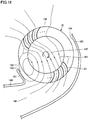
- Fig. 18 is a sectional view illustrating an airflow generated in vicinity of the blowout port of the air conditioner illustrated in Fig. 16 .
- an upstream outer space 146 is formed on the more upstream side of airflow than cross-flow fan 10
- an inner space 147 is formed on the inner side of cross-flow fan 10 (on the inner peripheral side of plural fan blades 21 arranged in the circumferential direction)
- a downstream outer space 148 is formed on the more downstream side of airflow than cross-flow fan 10.
- an airflow 161 passing through over blade surface 23 of fan blade 21 from upstream outer space 146 and directed toward inner space 147 is formed in an upstream region 141 of air-blow passage 126 defined with projections 153 and 154 as a boundary
- an airflow 161 passing through over blade surface 23 of fan blade 21 from inner space 147 and directed toward downstream outer space 148 is formed in a downstream region 142 of air-blow passage 126 defined with projections 153 and 154 as a boundary.
- an airflow vortex 162 is formed at a position adjacent to front wall portion 151.
- the present embodiment described the cross-flow fan provided in the air conditioner.
- the cross-flow fan is also applicable to other devices configured to discharge fluid, for example, air purifier, humidifier, cooling device, and ventilating device.
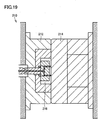
- Fig. 19 is a sectional view of a molding die used to produce cross-flow fan 10 illustrated in Fig. 1 .
- a molding die 210 has a fixated die 214 and a movable die 212.
- Fixated die 214 and movable die 212 define a cavity 216 formed in a shape substantially equal to that of cross-flow fan 10, resin having fluidity being injected in to cavity 216.
- Molding die 210 may be equipped with a heater, not illustrated in the drawings, to increase the fluidity of the resin injected into cavity 216.
- the arrangement of the heater is useful particularly when synthetic resins having enhanced strengths, for example, glass-filled AS resin, are used.
- cross-flow fan 10 used as an air blower can improve quietness during the operation while maintaining a high air-blow performance.
- Molding die 210 thus configured can produce cross-flow fan 10 superior in quietness during the rotation by molding the material resin.
- the present invention is mostly applied to home-use electric devices having an air-blow function such as air purifier and air conditioner.
Landscapes
- Engineering & Computer Science (AREA)
- Mechanical Engineering (AREA)
- General Engineering & Computer Science (AREA)
- Structures Of Non-Positive Displacement Pumps (AREA)
- Moulds For Moulding Plastics Or The Like (AREA)
Claims (7)
- Ventilateur tangentiel comportant une roue à pales (12),
la roue à pales (12) comprenant :une pluralité de pales (21) agencées dans une direction circonférentielle centrée sur un axe prédéfini (101) avec des intervalles qui diffèrent de manière aléatoire entre elles ; etune unité de support (13) raccordée à ladite pluralité de pales (21) pour supporter lesdites pales (21) de manière unifiée, dans lequelune pluralité desdites roues à pales (12) sont empilées les unes sur les autres le long d'une direction axiale dudit axe prédéfini (101),un diamètre intérieur d et un diamètre extérieur D desdites pales (21) satisfont une relation exprimée par 0,55 ≤ d/D ≤ 0,95,N représentant le nombre desdites pales (21), une longueur de corde L desdites pales (21), ledit diamètre extérieur D desdites pales (21), et M représentant le nombre desdites roues à pales (12) satisfont les relations exprimées par 0,6 ≤ L/(πD/N) ≤ 2,8 et 0,15 ≤ πD/(N x M) ≤ 3,77,la pluralité desdites roues à pales (12) sont empilées les unes sur les autres d'une telle manière qu'un angle de déplacement θ est généré dans les limites d'une plage définie par (1,2 x 360°/(N x M)) ≤ θ ≤ (360°/N) entre lesdites roues à pales (12) adjacentes les unes par rapport aux autres quand elles sont vues depuis la direction axiale dudit axe prédéfini (101), etledit angle de déplacement θ est défini de telle sorte que le nombre chevauchant desdites pales (21) ayant un angle d'installation égal dans toutes lesdites pales (21) est au plus 5 % de N x M représentant un nombre total desdites pales (21), caractérisé en ce queune relation exprimée par 0,05(πD/N) ≤ |Cn-(πD/N)| ≤ 0,24(πD/N) est satisfaite entre des pales adjacentes arbitraires desdites pales (21), où Cn (n = 1, 2, ..., N-1, N) est une longueur d'un arc de cercle centré sur ledit axe prédéfini (101) et reliant des extrémités périphériques extérieures desdites pales (21) adjacentes les unes par rapport aux autres sur un plan orthogonal audit axe prédéfini (101). - Ventilateur tangentiel selon la revendication 1, dans lequel
une relation exprimée par 0,68 ≤ d/D ≤ 0,86 est par ailleurs satisfaite. - Ventilateur tangentiel selon la revendication 1, dans lequel
une relation exprimée par 1,4 ≤ L/(πD/N) ≤ 2,1 est par ailleurs satisfaite. - Ventilateur tangentiel selon la revendication 1, dans lequel
une relation exprimée par 0,43 ≤ πD/(N x M) ≤ 2,83 est par ailleurs satisfaite. - Ventilateur tangentiel selon la revendication 1, dans lequel
le ventilateur tangentiel est formé à partir de résine. - Matrice de moulage utilisée à des fins de moulage du ventilateur tangentiel selon la revendication 5.
- Distributeur de fluide comportant une soufflante (115) comprenant le ventilateur tangentiel selon la revendication 1 et un moteur d'entraînement accouplé audit ventilateur tangentiel à des fins de rotation de ladite pluralité de pales (21).
Applications Claiming Priority (2)
| Application Number | Priority Date | Filing Date | Title |
|---|---|---|---|
| JP2009210465A JP4831707B2 (ja) | 2009-09-11 | 2009-09-11 | 貫流ファン、成型用金型および流体送り装置 |
| PCT/JP2010/065302 WO2011030749A1 (fr) | 2009-09-11 | 2010-09-07 | Ventilateur tangentiel, filière de moulage et dispositif d'apport de fluide |
Publications (3)
| Publication Number | Publication Date |
|---|---|
| EP2476908A1 EP2476908A1 (fr) | 2012-07-18 |
| EP2476908A4 EP2476908A4 (fr) | 2017-05-24 |
| EP2476908B1 true EP2476908B1 (fr) | 2019-01-02 |
Family
ID=43732421
Family Applications (1)
| Application Number | Title | Priority Date | Filing Date |
|---|---|---|---|
| EP10815346.1A Not-in-force EP2476908B1 (fr) | 2009-09-11 | 2010-09-07 | Ventilateur tangentiel, filière de moulage et dispositif d'apport de fluide |
Country Status (7)
| Country | Link |
|---|---|
| US (1) | US9347461B2 (fr) |
| EP (1) | EP2476908B1 (fr) |
| JP (1) | JP4831707B2 (fr) |
| KR (1) | KR101347987B1 (fr) |
| CN (1) | CN102483068B (fr) |
| MY (1) | MY153387A (fr) |
| WO (1) | WO2011030749A1 (fr) |
Cited By (1)
| Publication number | Priority date | Publication date | Assignee | Title |
|---|---|---|---|---|
| USD1057918S1 (en) | 2021-06-23 | 2025-01-14 | Sharkninja Operating Llc | Air purifier |
Families Citing this family (20)
| Publication number | Priority date | Publication date | Assignee | Title |
|---|---|---|---|---|
| CN103089661B (zh) * | 2011-11-04 | 2015-04-01 | 上海交通大学 | 横流风扇 |
| JP5143317B1 (ja) * | 2012-04-06 | 2013-02-13 | 三菱電機株式会社 | 空気調和装置の室内機 |
| CN104655054B (zh) * | 2013-11-20 | 2017-09-29 | 格力电器(合肥)有限公司 | 一种贯流风叶错位角测量方法及其测量装置 |
| CN106015087A (zh) * | 2016-07-21 | 2016-10-12 | 美的集团武汉制冷设备有限公司 | 贯流风轮、贯流风机和空调室内机 |
| JP7187140B2 (ja) * | 2017-08-03 | 2022-12-12 | 三菱重工サーマルシステムズ株式会社 | タンゼンシャルファン及び空気調和機 |
| JP7370220B2 (ja) * | 2017-09-27 | 2023-10-27 | ダイキン工業株式会社 | 空気調和機 |
| JP6843721B2 (ja) * | 2017-09-27 | 2021-03-17 | ダイキン工業株式会社 | 空気調和機 |
| CN108916077A (zh) * | 2018-07-16 | 2018-11-30 | 大连碧蓝节能环保科技有限公司 | 压气式贯流风机 |
| CN109209990B (zh) * | 2018-10-26 | 2024-07-02 | 珠海格力电器股份有限公司 | 贯流风叶、贯流风机、空调器 |
| CN109595197B (zh) * | 2018-12-07 | 2023-10-10 | 佛山市南海九洲普惠风机有限公司 | 一种风机 |
| JP7813665B2 (ja) * | 2019-10-30 | 2026-02-13 | ダイキン工業株式会社 | 空気調和機 |
| JP7608825B2 (ja) * | 2020-12-24 | 2025-01-07 | 株式会社富士通ゼネラル | 多翼ファン及び室内機 |
| JP7524776B2 (ja) * | 2021-01-26 | 2024-07-30 | 株式会社富士通ゼネラル | 多翼ファン及び室内機 |
| CN214660989U (zh) * | 2021-04-30 | 2021-11-09 | 中强光电股份有限公司 | 风扇结构 |
| CN114383197B (zh) * | 2021-12-30 | 2023-05-12 | 珠海格力电器股份有限公司 | 空调器 |
| EP4484754A4 (fr) * | 2022-02-21 | 2025-04-16 | Mitsubishi Electric Corporation | Ventilateur tangentiel |
| US12366372B2 (en) | 2023-01-25 | 2025-07-22 | General Filters, Inc. | Humidifier with crossflow fan |
| USD1120265S1 (en) | 2023-07-25 | 2026-03-24 | Sharkninja Operating Llc | Air purifier |
| CN117444440B (zh) * | 2023-11-06 | 2026-08-11 | 四川长虹模塑科技有限公司 | 多节贯流风扇的生产方法 |
| CN118640185B (zh) * | 2024-06-17 | 2025-01-28 | 广东晟辉科技股份有限公司 | 一种降低噪声的鼓风机扇叶结构 |
Family Cites Families (11)
| Publication number | Priority date | Publication date | Assignee | Title |
|---|---|---|---|---|
| JPS4884307A (fr) * | 1972-02-10 | 1973-11-09 | ||
| JP2758800B2 (ja) * | 1992-12-09 | 1998-05-28 | シャープ株式会社 | クロスフローファン |
| US6158954A (en) * | 1998-03-30 | 2000-12-12 | Sanyo Electric Co., Ltd. | Cross-flow fan and an air-conditioner using it |
| JP2000297946A (ja) * | 1999-02-10 | 2000-10-24 | Sanyo Electric Co Ltd | 空気調和機 |
| JP3695294B2 (ja) * | 2000-07-19 | 2005-09-14 | 松下電器産業株式会社 | クロスフローファン |
| JP3564462B2 (ja) * | 2002-03-15 | 2004-09-08 | 三菱重工業株式会社 | タンゼンシャルファン羽根車及び空気調和機 |
| JPWO2004029463A1 (ja) * | 2002-09-24 | 2006-01-26 | 東芝キヤリア株式会社 | 横流ファンおよびそれを備えた空気調和機 |
| JP2006118496A (ja) | 2004-09-24 | 2006-05-11 | Matsushita Electric Ind Co Ltd | クロスフローファン |
| JP3995010B2 (ja) | 2005-09-28 | 2007-10-24 | ダイキン工業株式会社 | 多翼送風機の羽根車及びその製造方法 |
| JP4799170B2 (ja) * | 2005-12-22 | 2011-10-26 | シャープ株式会社 | 空気調和機の室内機 |
| JP4788409B2 (ja) * | 2006-03-09 | 2011-10-05 | ソニー株式会社 | 横流送風装置及び電子機器 |
-
2009
- 2009-09-11 JP JP2009210465A patent/JP4831707B2/ja active Active
-
2010
- 2010-09-07 KR KR1020127009141A patent/KR101347987B1/ko not_active Expired - Fee Related
- 2010-09-07 EP EP10815346.1A patent/EP2476908B1/fr not_active Not-in-force
- 2010-09-07 US US13/395,225 patent/US9347461B2/en active Active
- 2010-09-07 CN CN201080040228.3A patent/CN102483068B/zh active Active
- 2010-09-07 WO PCT/JP2010/065302 patent/WO2011030749A1/fr not_active Ceased
- 2010-09-07 MY MYPI2012000993A patent/MY153387A/en unknown
Non-Patent Citations (1)
| Title |
|---|
| None * |
Cited By (1)
| Publication number | Priority date | Publication date | Assignee | Title |
|---|---|---|---|---|
| USD1057918S1 (en) | 2021-06-23 | 2025-01-14 | Sharkninja Operating Llc | Air purifier |
Also Published As
| Publication number | Publication date |
|---|---|
| JP2011058450A (ja) | 2011-03-24 |
| KR20120065388A (ko) | 2012-06-20 |
| JP4831707B2 (ja) | 2011-12-07 |
| US20120177477A1 (en) | 2012-07-12 |
| KR101347987B1 (ko) | 2014-01-07 |
| CN102483068B (zh) | 2014-11-26 |
| MY153387A (en) | 2015-01-29 |
| EP2476908A4 (fr) | 2017-05-24 |
| WO2011030749A1 (fr) | 2011-03-17 |
| US9347461B2 (en) | 2016-05-24 |
| EP2476908A1 (fr) | 2012-07-18 |
| CN102483068A (zh) | 2012-05-30 |
Similar Documents
| Publication | Publication Date | Title |
|---|---|---|
| US9347461B2 (en) | Cross-flow fan, molding die, and fluid feeder | |
| US9885364B2 (en) | Fan, molding die, and fluid feeder | |
| US9995303B2 (en) | Air conditioner | |
| JP4993791B2 (ja) | ファン、成型用金型および流体送り装置 | |
| JP4993792B2 (ja) | ファン、成型用金型および流体送り装置 | |
| CN110325745B (zh) | 螺旋桨式风扇、送风机以及空调机 | |
| US9303649B2 (en) | Cross flow fan and air-conditioning apparatus including same | |
| JP2013096378A (ja) | 遠心送風機 | |
| JP5179638B2 (ja) | ファン、成型用金型および流体送り装置 | |
| EP2000676B1 (fr) | Turbine et conditionneur d'air | |
| JP4874360B2 (ja) | 羽根車並びに多翼送風機並びに空気調和機 | |
| JP4775867B1 (ja) | ファン、成型用金型および流体送り装置 | |
| JP4906010B2 (ja) | ファン、成型用金型および流体送り装置 | |
| EP3015775B1 (fr) | Unité intérieure destinée à un dispositif de climatisation | |
| JP4906011B2 (ja) | ファン、成型用金型および流体送り装置 |
Legal Events
| Date | Code | Title | Description |
|---|---|---|---|
| PUAI | Public reference made under article 153(3) epc to a published international application that has entered the european phase |
Free format text: ORIGINAL CODE: 0009012 |
|
| 17P | Request for examination filed |
Effective date: 20120404 |
|
| AK | Designated contracting states |
Kind code of ref document: A1 Designated state(s): AL AT BE BG CH CY CZ DE DK EE ES FI FR GB GR HR HU IE IS IT LI LT LU LV MC MK MT NL NO PL PT RO SE SI SK SM TR |
|
| DAX | Request for extension of the european patent (deleted) | ||
| RA4 | Supplementary search report drawn up and despatched (corrected) |
Effective date: 20170426 |
|
| RIC1 | Information provided on ipc code assigned before grant |
Ipc: F04D 17/04 20060101AFI20170420BHEP Ipc: F04D 29/66 20060101ALI20170420BHEP |
|
| STAA | Information on the status of an ep patent application or granted ep patent |
Free format text: STATUS: EXAMINATION IS IN PROGRESS |
|
| 17Q | First examination report despatched |
Effective date: 20180201 |
|
| GRAP | Despatch of communication of intention to grant a patent |
Free format text: ORIGINAL CODE: EPIDOSNIGR1 |
|
| STAA | Information on the status of an ep patent application or granted ep patent |
Free format text: STATUS: GRANT OF PATENT IS INTENDED |
|
| INTG | Intention to grant announced |
Effective date: 20180713 |
|
| GRAS | Grant fee paid |
Free format text: ORIGINAL CODE: EPIDOSNIGR3 |
|
| GRAA | (expected) grant |
Free format text: ORIGINAL CODE: 0009210 |
|
| STAA | Information on the status of an ep patent application or granted ep patent |
Free format text: STATUS: THE PATENT HAS BEEN GRANTED |
|
| AK | Designated contracting states |
Kind code of ref document: B1 Designated state(s): AL AT BE BG CH CY CZ DE DK EE ES FI FR GB GR HR HU IE IS IT LI LT LU LV MC MK MT NL NO PL PT RO SE SI SK SM TR |
|
| RAP1 | Party data changed (applicant data changed or rights of an application transferred) |
Owner name: SHARP KABUSHIKI KAISHA |
|
| REG | Reference to a national code |
Ref country code: GB Ref legal event code: FG4D |
|
| RIN1 | Information on inventor provided before grant (corrected) |
Inventor name: OHTSUKA, MASAKI Inventor name: SHIRAICHI, YUKISHIGE |
|
| REG | Reference to a national code |
Ref country code: CH Ref legal event code: EP Ref country code: AT Ref legal event code: REF Ref document number: 1084729 Country of ref document: AT Kind code of ref document: T Effective date: 20190115 |
|
| REG | Reference to a national code |
Ref country code: IE Ref legal event code: FG4D |
|
| REG | Reference to a national code |
Ref country code: DE Ref legal event code: R096 Ref document number: 602010056297 Country of ref document: DE |
|
| REG | Reference to a national code |
Ref country code: SE Ref legal event code: TRGR |
|
| REG | Reference to a national code |
Ref country code: NL Ref legal event code: MP Effective date: 20190102 |
|
| REG | Reference to a national code |
Ref country code: LT Ref legal event code: MG4D |
|
| REG | Reference to a national code |
Ref country code: AT Ref legal event code: MK05 Ref document number: 1084729 Country of ref document: AT Kind code of ref document: T Effective date: 20190102 |
|
| PG25 | Lapsed in a contracting state [announced via postgrant information from national office to epo] |
Ref country code: NL Free format text: LAPSE BECAUSE OF FAILURE TO SUBMIT A TRANSLATION OF THE DESCRIPTION OR TO PAY THE FEE WITHIN THE PRESCRIBED TIME-LIMIT Effective date: 20190102 |
|
| PG25 | Lapsed in a contracting state [announced via postgrant information from national office to epo] |
Ref country code: PL Free format text: LAPSE BECAUSE OF FAILURE TO SUBMIT A TRANSLATION OF THE DESCRIPTION OR TO PAY THE FEE WITHIN THE PRESCRIBED TIME-LIMIT Effective date: 20190102 Ref country code: PT Free format text: LAPSE BECAUSE OF FAILURE TO SUBMIT A TRANSLATION OF THE DESCRIPTION OR TO PAY THE FEE WITHIN THE PRESCRIBED TIME-LIMIT Effective date: 20190502 Ref country code: NO Free format text: LAPSE BECAUSE OF FAILURE TO SUBMIT A TRANSLATION OF THE DESCRIPTION OR TO PAY THE FEE WITHIN THE PRESCRIBED TIME-LIMIT Effective date: 20190402 Ref country code: FI Free format text: LAPSE BECAUSE OF FAILURE TO SUBMIT A TRANSLATION OF THE DESCRIPTION OR TO PAY THE FEE WITHIN THE PRESCRIBED TIME-LIMIT Effective date: 20190102 Ref country code: ES Free format text: LAPSE BECAUSE OF FAILURE TO SUBMIT A TRANSLATION OF THE DESCRIPTION OR TO PAY THE FEE WITHIN THE PRESCRIBED TIME-LIMIT Effective date: 20190102 Ref country code: LT Free format text: LAPSE BECAUSE OF FAILURE TO SUBMIT A TRANSLATION OF THE DESCRIPTION OR TO PAY THE FEE WITHIN THE PRESCRIBED TIME-LIMIT Effective date: 20190102 |
|
| PG25 | Lapsed in a contracting state [announced via postgrant information from national office to epo] |
Ref country code: IS Free format text: LAPSE BECAUSE OF FAILURE TO SUBMIT A TRANSLATION OF THE DESCRIPTION OR TO PAY THE FEE WITHIN THE PRESCRIBED TIME-LIMIT Effective date: 20190502 Ref country code: HR Free format text: LAPSE BECAUSE OF FAILURE TO SUBMIT A TRANSLATION OF THE DESCRIPTION OR TO PAY THE FEE WITHIN THE PRESCRIBED TIME-LIMIT Effective date: 20190102 Ref country code: GR Free format text: LAPSE BECAUSE OF FAILURE TO SUBMIT A TRANSLATION OF THE DESCRIPTION OR TO PAY THE FEE WITHIN THE PRESCRIBED TIME-LIMIT Effective date: 20190403 Ref country code: LV Free format text: LAPSE BECAUSE OF FAILURE TO SUBMIT A TRANSLATION OF THE DESCRIPTION OR TO PAY THE FEE WITHIN THE PRESCRIBED TIME-LIMIT Effective date: 20190102 Ref country code: BG Free format text: LAPSE BECAUSE OF FAILURE TO SUBMIT A TRANSLATION OF THE DESCRIPTION OR TO PAY THE FEE WITHIN THE PRESCRIBED TIME-LIMIT Effective date: 20190402 |
|
| REG | Reference to a national code |
Ref country code: DE Ref legal event code: R097 Ref document number: 602010056297 Country of ref document: DE |
|
| PG25 | Lapsed in a contracting state [announced via postgrant information from national office to epo] |
Ref country code: AL Free format text: LAPSE BECAUSE OF FAILURE TO SUBMIT A TRANSLATION OF THE DESCRIPTION OR TO PAY THE FEE WITHIN THE PRESCRIBED TIME-LIMIT Effective date: 20190102 Ref country code: AT Free format text: LAPSE BECAUSE OF FAILURE TO SUBMIT A TRANSLATION OF THE DESCRIPTION OR TO PAY THE FEE WITHIN THE PRESCRIBED TIME-LIMIT Effective date: 20190102 Ref country code: DK Free format text: LAPSE BECAUSE OF FAILURE TO SUBMIT A TRANSLATION OF THE DESCRIPTION OR TO PAY THE FEE WITHIN THE PRESCRIBED TIME-LIMIT Effective date: 20190102 Ref country code: CZ Free format text: LAPSE BECAUSE OF FAILURE TO SUBMIT A TRANSLATION OF THE DESCRIPTION OR TO PAY THE FEE WITHIN THE PRESCRIBED TIME-LIMIT Effective date: 20190102 Ref country code: RO Free format text: LAPSE BECAUSE OF FAILURE TO SUBMIT A TRANSLATION OF THE DESCRIPTION OR TO PAY THE FEE WITHIN THE PRESCRIBED TIME-LIMIT Effective date: 20190102 Ref country code: EE Free format text: LAPSE BECAUSE OF FAILURE TO SUBMIT A TRANSLATION OF THE DESCRIPTION OR TO PAY THE FEE WITHIN THE PRESCRIBED TIME-LIMIT Effective date: 20190102 Ref country code: SK Free format text: LAPSE BECAUSE OF FAILURE TO SUBMIT A TRANSLATION OF THE DESCRIPTION OR TO PAY THE FEE WITHIN THE PRESCRIBED TIME-LIMIT Effective date: 20190102 |
|
| PLBE | No opposition filed within time limit |
Free format text: ORIGINAL CODE: 0009261 |
|
| STAA | Information on the status of an ep patent application or granted ep patent |
Free format text: STATUS: NO OPPOSITION FILED WITHIN TIME LIMIT |
|
| PG25 | Lapsed in a contracting state [announced via postgrant information from national office to epo] |
Ref country code: SM Free format text: LAPSE BECAUSE OF FAILURE TO SUBMIT A TRANSLATION OF THE DESCRIPTION OR TO PAY THE FEE WITHIN THE PRESCRIBED TIME-LIMIT Effective date: 20190102 |
|
| 26N | No opposition filed |
Effective date: 20191003 |
|
| PG25 | Lapsed in a contracting state [announced via postgrant information from national office to epo] |
Ref country code: SI Free format text: LAPSE BECAUSE OF FAILURE TO SUBMIT A TRANSLATION OF THE DESCRIPTION OR TO PAY THE FEE WITHIN THE PRESCRIBED TIME-LIMIT Effective date: 20190102 |
|
| PG25 | Lapsed in a contracting state [announced via postgrant information from national office to epo] |
Ref country code: TR Free format text: LAPSE BECAUSE OF FAILURE TO SUBMIT A TRANSLATION OF THE DESCRIPTION OR TO PAY THE FEE WITHIN THE PRESCRIBED TIME-LIMIT Effective date: 20190102 |
|
| REG | Reference to a national code |
Ref country code: DE Ref legal event code: R119 Ref document number: 602010056297 Country of ref document: DE |
|
| PG25 | Lapsed in a contracting state [announced via postgrant information from national office to epo] |
Ref country code: MC Free format text: LAPSE BECAUSE OF FAILURE TO SUBMIT A TRANSLATION OF THE DESCRIPTION OR TO PAY THE FEE WITHIN THE PRESCRIBED TIME-LIMIT Effective date: 20190102 |
|
| REG | Reference to a national code |
Ref country code: CH Ref legal event code: PL |
|
| PG25 | Lapsed in a contracting state [announced via postgrant information from national office to epo] |
Ref country code: CH Free format text: LAPSE BECAUSE OF NON-PAYMENT OF DUE FEES Effective date: 20190930 Ref country code: DE Free format text: LAPSE BECAUSE OF NON-PAYMENT OF DUE FEES Effective date: 20200401 Ref country code: LU Free format text: LAPSE BECAUSE OF NON-PAYMENT OF DUE FEES Effective date: 20190907 Ref country code: IE Free format text: LAPSE BECAUSE OF NON-PAYMENT OF DUE FEES Effective date: 20190907 Ref country code: LI Free format text: LAPSE BECAUSE OF NON-PAYMENT OF DUE FEES Effective date: 20190930 |
|
| REG | Reference to a national code |
Ref country code: BE Ref legal event code: MM Effective date: 20190930 |
|
| PG25 | Lapsed in a contracting state [announced via postgrant information from national office to epo] |
Ref country code: BE Free format text: LAPSE BECAUSE OF NON-PAYMENT OF DUE FEES Effective date: 20190930 |
|
| GBPC | Gb: european patent ceased through non-payment of renewal fee |
Effective date: 20190907 |
|
| PG25 | Lapsed in a contracting state [announced via postgrant information from national office to epo] |
Ref country code: FR Free format text: LAPSE BECAUSE OF NON-PAYMENT OF DUE FEES Effective date: 20190930 Ref country code: GB Free format text: LAPSE BECAUSE OF NON-PAYMENT OF DUE FEES Effective date: 20190907 |
|
| PG25 | Lapsed in a contracting state [announced via postgrant information from national office to epo] |
Ref country code: CY Free format text: LAPSE BECAUSE OF FAILURE TO SUBMIT A TRANSLATION OF THE DESCRIPTION OR TO PAY THE FEE WITHIN THE PRESCRIBED TIME-LIMIT Effective date: 20190102 |
|
| PG25 | Lapsed in a contracting state [announced via postgrant information from national office to epo] |
Ref country code: MT Free format text: LAPSE BECAUSE OF FAILURE TO SUBMIT A TRANSLATION OF THE DESCRIPTION OR TO PAY THE FEE WITHIN THE PRESCRIBED TIME-LIMIT Effective date: 20190102 Ref country code: HU Free format text: LAPSE BECAUSE OF FAILURE TO SUBMIT A TRANSLATION OF THE DESCRIPTION OR TO PAY THE FEE WITHIN THE PRESCRIBED TIME-LIMIT; INVALID AB INITIO Effective date: 20100907 |
|
| PGFP | Annual fee paid to national office [announced via postgrant information from national office to epo] |
Ref country code: IT Payment date: 20210922 Year of fee payment: 12 |
|
| PG25 | Lapsed in a contracting state [announced via postgrant information from national office to epo] |
Ref country code: MK Free format text: LAPSE BECAUSE OF FAILURE TO SUBMIT A TRANSLATION OF THE DESCRIPTION OR TO PAY THE FEE WITHIN THE PRESCRIBED TIME-LIMIT Effective date: 20190102 |
|
| PG25 | Lapsed in a contracting state [announced via postgrant information from national office to epo] |
Ref country code: IT Free format text: LAPSE BECAUSE OF NON-PAYMENT OF DUE FEES Effective date: 20220907 |
|
| PGFP | Annual fee paid to national office [announced via postgrant information from national office to epo] |
Ref country code: SE Payment date: 20230920 Year of fee payment: 14 |
|
| REG | Reference to a national code |
Ref country code: SE Ref legal event code: EUG |
|
| PG25 | Lapsed in a contracting state [announced via postgrant information from national office to epo] |
Ref country code: SE Free format text: LAPSE BECAUSE OF NON-PAYMENT OF DUE FEES Effective date: 20240908 |