EP2476954B1 - Chaudière à charbon pulvérisée - Google Patents
Chaudière à charbon pulvérisée Download PDFInfo
- Publication number
- EP2476954B1 EP2476954B1 EP10815102.8A EP10815102A EP2476954B1 EP 2476954 B1 EP2476954 B1 EP 2476954B1 EP 10815102 A EP10815102 A EP 10815102A EP 2476954 B1 EP2476954 B1 EP 2476954B1
- Authority
- EP
- European Patent Office
- Prior art keywords
- air
- furnace
- swirl
- pulverized coal
- combustion
- Prior art date
- Legal status (The legal status is an assumption and is not a legal conclusion. Google has not performed a legal analysis and makes no representation as to the accuracy of the status listed.)
- Active
Links
Images



Classifications
-
- F—MECHANICAL ENGINEERING; LIGHTING; HEATING; WEAPONS; BLASTING
- F23—COMBUSTION APPARATUS; COMBUSTION PROCESSES
- F23L—SUPPLYING AIR OR NON-COMBUSTIBLE LIQUIDS OR GASES TO COMBUSTION APPARATUS IN GENERAL ; VALVES OR DAMPERS SPECIALLY ADAPTED FOR CONTROLLING AIR SUPPLY OR DRAUGHT IN COMBUSTION APPARATUS; INDUCING DRAUGHT IN COMBUSTION APPARATUS; TOPS FOR CHIMNEYS OR VENTILATING SHAFTS; TERMINALS FOR FLUES
- F23L9/00—Passages or apertures for delivering secondary air for completing combustion of fuel
- F23L9/02—Passages or apertures for delivering secondary air for completing combustion of fuel by discharging the air above the fire
-
- F—MECHANICAL ENGINEERING; LIGHTING; HEATING; WEAPONS; BLASTING
- F23—COMBUSTION APPARATUS; COMBUSTION PROCESSES
- F23C—METHODS OR APPARATUS FOR COMBUSTION USING FLUID FUEL OR SOLID FUEL SUSPENDED IN A CARRIER GAS OR AIR
- F23C6/00—Combustion apparatus characterised by the combination of two or more combustion chambers or combustion zones, e.g. for staged combustion
- F23C6/04—Combustion apparatus characterised by the combination of two or more combustion chambers or combustion zones, e.g. for staged combustion in series connection
- F23C6/045—Combustion apparatus characterised by the combination of two or more combustion chambers or combustion zones, e.g. for staged combustion in series connection with staged combustion in a single enclosure
- F23C6/047—Combustion apparatus characterised by the combination of two or more combustion chambers or combustion zones, e.g. for staged combustion in series connection with staged combustion in a single enclosure with fuel supply in stages
-
- F—MECHANICAL ENGINEERING; LIGHTING; HEATING; WEAPONS; BLASTING
- F22—STEAM GENERATION
- F22B—METHODS OF STEAM GENERATION; STEAM BOILERS
- F22B21/00—Water-tube boilers of vertical or steeply-inclined type, i.e. the water-tube sets being arranged vertically or substantially vertically
-
- F—MECHANICAL ENGINEERING; LIGHTING; HEATING; WEAPONS; BLASTING
- F23—COMBUSTION APPARATUS; COMBUSTION PROCESSES
- F23C—METHODS OR APPARATUS FOR COMBUSTION USING FLUID FUEL OR SOLID FUEL SUSPENDED IN A CARRIER GAS OR AIR
- F23C6/00—Combustion apparatus characterised by the combination of two or more combustion chambers or combustion zones, e.g. for staged combustion
- F23C6/04—Combustion apparatus characterised by the combination of two or more combustion chambers or combustion zones, e.g. for staged combustion in series connection
-
- F—MECHANICAL ENGINEERING; LIGHTING; HEATING; WEAPONS; BLASTING
- F23—COMBUSTION APPARATUS; COMBUSTION PROCESSES
- F23C—METHODS OR APPARATUS FOR COMBUSTION USING FLUID FUEL OR SOLID FUEL SUSPENDED IN A CARRIER GAS OR AIR
- F23C7/00—Combustion apparatus characterised by arrangements for air supply
- F23C7/002—Combustion apparatus characterised by arrangements for air supply the air being submitted to a rotary or spinning motion
- F23C7/004—Combustion apparatus characterised by arrangements for air supply the air being submitted to a rotary or spinning motion using vanes
-
- F—MECHANICAL ENGINEERING; LIGHTING; HEATING; WEAPONS; BLASTING
- F23—COMBUSTION APPARATUS; COMBUSTION PROCESSES
- F23C—METHODS OR APPARATUS FOR COMBUSTION USING FLUID FUEL OR SOLID FUEL SUSPENDED IN A CARRIER GAS OR AIR
- F23C7/00—Combustion apparatus characterised by arrangements for air supply
- F23C7/008—Flow control devices
-
- F—MECHANICAL ENGINEERING; LIGHTING; HEATING; WEAPONS; BLASTING
- F23—COMBUSTION APPARATUS; COMBUSTION PROCESSES
- F23C—METHODS OR APPARATUS FOR COMBUSTION USING FLUID FUEL OR SOLID FUEL SUSPENDED IN A CARRIER GAS OR AIR
- F23C99/00—Subject-matter not provided for in other groups of this subclass
-
- F—MECHANICAL ENGINEERING; LIGHTING; HEATING; WEAPONS; BLASTING
- F23—COMBUSTION APPARATUS; COMBUSTION PROCESSES
- F23L—SUPPLYING AIR OR NON-COMBUSTIBLE LIQUIDS OR GASES TO COMBUSTION APPARATUS IN GENERAL ; VALVES OR DAMPERS SPECIALLY ADAPTED FOR CONTROLLING AIR SUPPLY OR DRAUGHT IN COMBUSTION APPARATUS; INDUCING DRAUGHT IN COMBUSTION APPARATUS; TOPS FOR CHIMNEYS OR VENTILATING SHAFTS; TERMINALS FOR FLUES
- F23L9/00—Passages or apertures for delivering secondary air for completing combustion of fuel
- F23L9/04—Passages or apertures for delivering secondary air for completing combustion of fuel by discharging the air beyond the fire, i.e. nearer the smoke outlet
-
- F—MECHANICAL ENGINEERING; LIGHTING; HEATING; WEAPONS; BLASTING
- F23—COMBUSTION APPARATUS; COMBUSTION PROCESSES
- F23C—METHODS OR APPARATUS FOR COMBUSTION USING FLUID FUEL OR SOLID FUEL SUSPENDED IN A CARRIER GAS OR AIR
- F23C2201/00—Staged combustion
- F23C2201/10—Furnace staging
- F23C2201/101—Furnace staging in vertical direction, e.g. alternating lean and rich zones
Definitions
- the present invention relates to a pulverized coal boiler and more particularly to a pulverized coal boiler including an after-air nozzle on the downstream side of a burner installed in a furnace of the pulverized coal boiler.
- the pulverized coal boiler In the pulverized coal boiler, it is requested to suppress the NOx concentration contained in combustion gas generated when the pulverized coal fuel is burned by the pulverized coal boiler and as a measure against it, a double combustion method is mainly used.
- a pulverized coal boiler with the double combustion method applied to, for example, as disclosed in Japanese Patent Laid-open No. Hei 9(1997)-310807 is structured so as to install a pulverized coal burner in the furnace of the pulverized coal boiler and an after-air nozzle on the downstream side of the burner, feed pulverized coal fuel and combustion air from the burner, feed only combustion air from the after-air nozzle, thereby burning the pulverized coal fuel.
- an after-air nozzle having a structure that the flowing form of the injection flow fed from the after-air nozzle is adjusted so as to have both a straight flow and a swirl flow is disclosed.
- Japanese Patent Appl. Laid-open No. 2000-097430 A aims at providing a boiler for reducing an unburned component of a fuel in a boiler furnace by improving a mixing performance of a combustion gas at a center of the furnace with two stage combustion air without strengthening power of a forced blower.
- a pressure loss is reduced by increasing a channel sectional area of an air introducing unit of a two-stage combustion air supplying apparatus. That is, a sectional area of a channel of an inlet of the air or gas is increased more than that of an outlet of the air or gas, and a straight tube is provided at the outlet of the air or gas in the combustion air or gas supplying apparatus.
- European Patent Appl. Laid-open No. 1 653 152 A2 discloses an after-air nozzle and a boiler having same that is capable of reducing NOx and CO at the same time.
- the after-air nozzle has a vena contracta such that an outside diameter of a flow passage diminishes towards the air-jetting port which supplies air to a boiler, and a changing apparatus of a flow passage cross-sectional area to change a flow passage cross-sectional area of the vena contracta.
- Japanese Patent Appl. Laid-open No. S59(1984)-109714 A aims at reducing NOx without increasing unburnt matter in exhaust gas by a method wherein straight forward air is supplied from the central part of an after-air feeding device, while swirl air is supplied from its outer peripheral part.
- a part of the air supplied from a wind box is passed through a swirler and thereby turned into a swirl air stream, which is passed through an outside air passage and jetted from an after-air port into a furnace.
- the stream is expanded in the directions of the periphery of the furnace and of a water wall due to its swirling force.
- the remaining air is regulated in its flow rate by a damper and then introduced in an inside air passage so as to be turned into straight forward air in order to be jetted from the after-air port in the central part of the furnace.
- the after-air nozzle of the boiler disclosed in Japanese Patent Laid-open No. Hei 4(1992)-52414 is not questionable because the shape of the opening of the outlet of the after-air nozzle is circular.
- the opening of the outlet of the after-air nozzle is formed in a rectangular shape, it is expected that in the flow of the injection flow injected from the outlet of the after-air nozzle to form a deflection flow caused by the rectangular opening, and it is difficult to form a swirl flow along the inner wall of the furnace of the boiler.
- An object of the present invention is to provide a pulverized coal boiler, when the opening of the.outlet of the after-air nozzle is formed in a rectangular shape, for permitting an injection flow of combustion air injecting from the after-air nozzle into the furnace to be fed to the vicinity of the inner wall of the furnace and making it possible to reduce unburned components and CO which exist in the vicinity of the inner wall of the furnace.
- the present invention provides a pulverized coal boiler having the features of claim 1.
- Preferred embodiments of the invention are described in the dependent claims.
- a pulverized coal boiler can be realized, when the opening of the outlet of each after-air nozzle is formed in a rectangular shape, a pulverized coal boiler for permitting an injection flow of combustion air injecting from the after-air nozzle into the furnace to be fed to the vicinity of the inner wall of the furnace and making it possible to reduce unburned components and CO which exist in the vicinity of the inner wall of the furnace.
- Fig. 1 shows a schematic structure of the pulverized coal boiler including the after-air nozzles that is an embodiment of the present invention.
- a plurality of burners 2 for feeding and burning both pulverized coal fuel and combustion air inside the furnace 1 are installed away from each other in the horizontal direction, and combustion air of a volume lower than the theoretical air ratio necessary for perfect combustion of pulverized coal fuel is fed into the furnace 1 from the burners 2, and the pulverized coal is burned in a state of insufficient air, and NOx generated due to combustion of the pulverized coal by the burners in the reductive atmosphere is reduced to nitrogen, and the generation of NOx contained in combustion gas 5 of the burner section is suppressed.
- a plurality of after-air nozzles 3 and 4 for feeding combustion air into the furnace 1 are installed at the upper and lower stages away from each other in the horizontal direction.
- the after-air nozzles 3 are installed on the wall surface of the furnace 1 on the downstream side of the combustion gas above the wall surface of the furnace 1 where the after-air nozzles 4 are installed and a structure that the upper after-air nozzles 3 and the lower after-air nozzles 4 compose the after-air nozzles arranged at the upper and lower stages is adopted.
- an injection flow 7 of combustion air 30 is fed into the furnace 1, thus in a reductive atmosphere formed in the furnace 1 by the burners 2, to burn perfectly unburned components remaining due to insufficient oxygen and generated CO (carbon monoxide), the combustion air 30 slightly more than the air volume which is a deficiency of the theoretical air ratio is fed into the furnace 1 to burn the unburned components and CO.
- an injection flow 8 of the combustion air 30 is fed along the inner wall of the furnace 1, thus compared with the combustion air fed from the upper after-air nozzles 3, the injection flow 8 (combustion air) of a low flow quantity and a low flow rate is fed into the furnace 1 of the boiler.
- the injection flow 8 of a low flow quantity and a low flow rate is fed in the vicinity of the inner wall of the furnace 1, thus to the unburned components and CO easily staying in the vicinity of the inner wall of the furnace 1, combustion air can be fed effectively, and the unburned components and CO staying in the vicinity of the inner wall of the furnace 1 are burned to combustion exhaust gas 6, so that the unburned components and CO staying in the vicinity of the inner wall of the furnace 1 can be reduced.
- combustion exhaust gas 6 generated by burning the unburned components and CO in the furnace 1 flows down toward the downstream side of the furnace 1 and is discharged outside the system from the furnace 1.
- Fig. 2 shows a front view of the lower after-air nozzle 4 viewed from the inside of the furnace 1 among the upper and lower after-air nozzles 3 and 4 which are installed on the wall surface of the furnace 1 of the pulverized coal boiler which is an embodiment of the present invention shown in Fig. 1 and Fig. 3 shows a cross sectional view of the line A-A of the lower after-air nozzle 4 shown in Fig. 2 .
- an opening 4a which is an outlet of the after-air nozzle 4 interconnected to the inside of the furnace 1 is formed in a rectangular shape.
- a cylindrical section 20 extending in the flow path direction of the combustion air 30 flowing inside the after-air nozzle 4 for defining the minimum flow path area of the combustion air 30 is installed concentrically inside the after-air nozzle 4 and inside the cylindrical section 20, a circular swirl blade 10 for giving a swirl force to the combustion air 30 flowing in the flow path of the minimum flow path area defined by the cylindrical section 20 is installed.
- the flow path of the lower after-air nozzle 4 is formed so that the flow path area is expanded from the position of the minimum flow path area defined by the cylindrical section 20 installed at the central portion in the longitudinal direction of the flow path toward the opening 4a interconnected to the inside of the furnace 1 and the opening 4a of the lower after-air nozzle 4 which is a flow path outlet interconnected to the inside of the furnace 1 is formed in a rectangular shape.
- the opening 4a of the lower after-air nozzle 4 which is a flow path outlet interconnected to the inside of the furnace 1 is formed in a rectangular shape.
- there is a gap 21 between the cylindrical section 20 and the after-air nozzle 4 though a structure that the outside diameter of the cylindrical section 20 is permitted to adhere closely to the inside of the rectangular flow path of the after-air nozzle 4 to eliminate the gap 21 provides no trouble.
- the circular swirl blade 10 installed inside the cylindrical section 20 for giving a swirl force to the combustion air 30 is connected to a drive unit 70 with a connection shaft 31 and by the drive of the drive unit 70 and via the connection shaft 31, the circular swirl blade 10 is structured so as to move back and forth inside the cylindrical section 20 in the flow direction of the combustion air 30.
- the measured values of the flow rate distribution at the position directly beneath the flow of the opening 4a of the after-air nozzle 4 in the radial direction X (corresponding to the radial direction X shown in Fig. 2 ) on the horizontal surface are shown in Fig. 8 together with a conventional embodiment.
- the flow rate distribution at the outlet of the lower after-air nozzle 4 of this embodiment is indicated with a solid line 50 and as a conventional embodiment, the flow rate distribution of an after-air nozzle structure without the cylindrical section 20 is indicated with a dashed line 51.
- the lower after-air nozzle 4 of this embodiment since the swirl blade 10 for giving a swirl force to the combustion air 30 flowing down inside the cylindrical section 20 installed in the central position in the longitudinal direction in the flow path of the lower after-air nozzle 4 is installed, the swirl flow caused by the swirl blade 10 is protected inside the cylindrical section 20, so that a swirl flow free of a deflection flow can be formed.
- the injection flow 8 of the combustion air 30 injecting from the opening 4a of the outlet of the lower after-air nozzle 4, along the inner wall of the furnace 1, for an axis of symmetry of the axial line A-A of the after-air nozzle 4, is formed so as to expand uniformly on both sides on the horizontal surface, so that an effect can be obtained that to the unburned components and CO existing in the vicinity of the inner wall of the furnace 1, the injection flow 8 can be fed to burn and the unburned components and CO existing in the vicinity of the inner wall of the furnace 1 can surely be reduced.
- the maximum value of the flow rate is seen only on the left side and it is found that the injection flow is deflected and injected from the after-air nozzle.
- the region of feeding the injection flow 8 from the after-air nozzle is narrow, so that an unreacted region is expanded and the reduction effect of the unburned components and CO in the vicinity of the inner wall of the furnace 1 is lowered.
- a blade angle ⁇ which is an arrangement angle of the swirl blade with the flow of combustion air regarding the swirl blade composing the swirl blade 10.
- the blade angle ⁇ is increased, the resistance of the flow of combustion air is increased and the pressure loss is increased. If the pressure loss is increased, a necessary quantity of combustion air cannot be fed into the furnace 1 from the lower after-air nozzle 4, so that for the pressure loss allowable in the lower after-air nozzle 4, an upper limit value "a" is set.
- Fig. 9 in the lower after-air nozzle 4 of this embodiment, is a characteristic diagram showing the relationship between the swirl number SW and the pressure loss of the swirl blade 10 installed inside the cylindrical section 20. Further, Fig. 10 is a schematic view of the swirl blade when obtaining the swirl number SW in the swirl blade 10 of this embodiment.
- Gx axial momentum
- p fluid density
- U axial flow rate
- Rh axial radius
- R flow path radius
- Fig. 9 the characteristic line segment showing the relationship between the swirl number SW and the pressure loss by the swirl blade 10 installed in the after-air nozzle 4 is indicated by a solid line as an approximate line A of the pressure loss and swirl number.
- the swirl number SW 1.3 when the dashed line of the upper limit value "a” of the pressure loss and the solid line A cross each other is an upper limit value of the swirl number SW and the blade angle ⁇ of the swirl blade 10 in the case of the swirl number SW 1.3, as shown in Table 1, is 62°.
- the swirl number SW of the swirl blade 10 installed inside the cylindrical section 20 of the lower after-air nozzle 4 of the embodiment of the present invention is set within the range from 0.7 to 1.3 when the blade angle ⁇ is within the range from 45° to 62°, the range is an optimum range.
- the swirl number SW of the swirl blade 10 of the lower after-air nozzle 4 when the blade angle ⁇ of the swirl blade is within the range from 45° to 62°, is set within the range from 0.7 to 1.3 and the cylindrical section 20 is installed, thus a swirl flow free of a deflection flow can be formed.
- the injection flow 8 of the combustion air 30 injecting from the opening of the lower after-air nozzle 4 interconnected to the inside of the furnace 1, along the inner wall of the furnace 1, for an axis of symmetry of the axial line A-A of the after-air nozzle 4, is expanded uniformly on both sides on the horizontal surface, so that an effect can be obtained that to the unburned components and CO existing in the vicinity of the inner wall of the furnace 1, the injection flow 8 can be fed to burn and the unburned components and CO existing in the vicinity of the inner wall of the furnace 1 can surely be reduced. Furthermore, the generation of NOx can be suppressed.
- a pulverized coal boiler capable of feeding the injection flow of combustion air injecting into the furnace from the after-air nozzle to the vicinity of the inner wall of the furnace and reducing the unburned components and CO existing in the vicinity of the inner wall of the furnace can be realized.
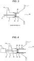
- Figs. 4 and 5 show a cross sectional view of the lower after-air nozzle of the embodiment installed in the furnace of the pulverized coal boiler of the present invention.
- the lower after-air nozzle 4 installed in the furnace of the pulverized coal boiler of this embodiment shown in Figs. 4 and 5 is common to the lower after-air nozzle of the preceding embodiment shown in Figs. 2 and 3 in the basic constitution, so that the explanation of the constitution common to the two is omitted and only the different constitution will be explained below.
- the lower after-air nozzle of this embodiment shown in Figs. 4 and 5 is formed so that the length of the cylindrical section 20 is extended from the middle portion of the flow path of the after-air nozzle 4 in the longitudinal direction up to the opening 4a of the lower after-air nozzle which is the flow path outlet interconnected to the inside of the furnace 1.
- the swirl blade 10 installed inside the cylindrical section 20 is connected to the drive unit 70 via the connection shaft 31, and by the drive operation of the drive unit 70, the swirl blade 10 can move in the longitudinal direction of the flow path inside the cylindrical section 20 via the connection shaft 31, and the swirl blade 10 is structured, as shown in Fig. 5 , so as to move to the leading edge side of the cylindrical section 20 facing the side of the furnace 1.
- connection shaft 31 is supported rotatably by a support section 33 installed on the inner wall of the lower after-air nozzle 4.
- the length of the cylindrical section 20 is extended up to the opening 4a of the flow path of the after-air nozzle 4, thus the swirl flow of the combustion air 30 formed by the swirl blade 10 inside the cylindrical section 20 is protected, so that the injection flow 8 injected into the furnace 1 from the opening 4a of the after-air nozzle 4 can form a stronger swirl flow expanded uniformly on both sides along the wall surface of the furnace 1 than the embodiment shown in Figs. 2 and 3 .
- the swirl blade 10 can move in the longitudinal direction of the flow path inside the cylindrical section 20, and the swirl blade 10 moves to the leading edge side of the cylindrical section 20 facing the side of the furnace 1 shown in Fig. 5 , thus the approach section of the swirl flow is shortened, so that the swirl strength becomes weak, and the injection flow 8 injecting from the opening 4a of the lower after-air nozzle 4, within the range from the injection flow along the inner wall of the furnace 1 to the injection flow flowing inside the furnace 1, can be regulated in accordance with the combustion state of the boiler. Therefore, there is an advantage that the swirl strength of the injection flow 8 injecting from the lower after-air nozzle 4 into the furnace 1 can be regulated.
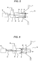
- the length of the cylindrical section 20 is extended up to the opening 4a of the lower after-air nozzle 4, thus there are possibilities that combustion ash may be deposited on the outer peripheral wall of the cylindrical section 20. Therefore, at least one leak hole 24 is formed in the cylindrical section 20, thus a highly reliable lower after-air nozzle 4 for permitting a part of the combustion air 30 to flow down as leak air 25 along the outer peripheral wall of the cylindrical section 20 from the leak hole 24 and suppress the deposition of combustion ash on the outer peripheral wall of the cylindrical section 20 can be provided.
- combustion ash is deposited mainly on the leading edge of the cylindrical section 20, and as shown in Fig. 6 , the leak holes 24 are formed at the upstream position of the leading edge of the cylindrical section 20, and the leak air 25 flows down along the outer peripheral wall of the cylindrical section, thus the similar effect can be obtained.
- a pulverized coal boiler capable of feeding the injection flow of combustion air injecting into the furnace from the after-air nozzle to the vicinity of the inner wall of the furnace and reducing the unburned components and CO existing in the vicinity of the inner wall of the furnace can be realized.
- Fig. 7 shows a cross sectional view of the lower after-air nozzle of another embodiment installed in the furnace of the pulverized coal boiler.
- the lower after-air nozzle 4 installed in the furnace of the pulverized coal boiler of this embodiment shown in Fig. 7 is common to the lower after-air nozzle of the embodiment shown in Fig. 6 in the basic constitution, so that the explanation of the constitution common to the two is omitted and only the different constitution will be explained below.
- the lower after-air nozzle 4 of this embodiment shown in Fig. 7 is structured so as to include a rectifying plate 35 for rectifying the flow of the combustion air 30 on the upstream side of the swirl blade 10.
- the rectifying plate 35 is arranged, the flow of the combustion air 30 on the upstream side of the swirl blade 10 is rectified and flows into the swirl blade 10, so that there is an advantage that the swirl flow by the swirl blade 10 is suppressed from generation of a deflection flow of air and a more uniform swirl flow free of a deflection flow can be formed.
- the rectifying plate 35 since the flow of the combustion air 30 is rectified by the rectifying plate 35, an effect of reducing the pressure loss of the combustion air 30 flowing down in the flow path of the lower after-air nozzle 4 can be expected. Further, the rectifying plate 35 of this embodiment can be applied to the structure of the lower after-air nozzles 4 shown in Figs. 2 to 6 and the similar effect can be obtained.
- a pulverized coal boiler for permitting an injection flow of combustion air injecting from the after-air nozzles into the furnace to be fed in the vicinity of the inner wall of the furnace and making it possible to reduce unburned components and CO which exist in the vicinity of the inner wall of the furnace can be realized.
- Fig. 11 in the pulverized coal boiler including the lower after-air nozzles 4 and the upper after-air nozzles 3 composing the upper and lower after-air nozzles of this embodiment, shows an embodiment of the intra-furnace air ratio distribution of the furnace 1.
- the upper after-air nozzle 3 feeds an injection flow 7 to the furnace center of the furnace 1 and the lower after-air nozzle 4 feeds the injection flow 8 to the vicinity of the inner wall of the furnace 1, thus after-air of combustion air can be fed more quickly and uniformly into the furnace 1, and the unburned components and CO can be reduced, and furthermore, the generation of NOx can be suppressed.
- the burner air ratio in the upstream portion of the lower after-air nozzle 4 is set to 0.8 (20% smaller than the theoretical air volume necessary for perfect combustion of pulverized coal fuel), and so that the air ratio after the injection flow 8 injecting as combustion air from the lower after-air nozzle 4 is injected becomes 0.9, air of an air ratio of 0.1 is fed from the lower after-air nozzle 4.
- the upper after-air nozzle 3 feeds residual combustion air by the injection flow 7 and the burner air ratio in the upstream portion of the upper after-air nozzle 3 is operated, for example, so as to be an air ratio of 1.2.
- the unburned components and CO can be reduced. Further, there is an advantage that the lower after-air nozzle 4 feeds a small amount of combustion air to cause slow combustion, thus the generation of thermal NOx can be suppressed.
- Figs. 12 and 13 the images of the injection flows 7 and 8 on the cross sections of the furnace in the positions of the upper and lower after-air nozzles 3 and 4 shown in Fig. 11 are shown.
- the upper after-air nozzles 3 feed combustion air as the injection flow 7 to CO of high concentration and an unburned component region 41 that exists at the furnace center of the furnace 1.
- the lower after-air nozzles 4 feed combustion air as the injection flow 8 to CO of high concentration and an unburned component region 42 that exists in the vicinity of the inner wall of the furnace 1.
- the combustion air fed to the inner space of the furnace 1 is fed into the furnace 1 by the injection flow 7 from the upper after-air nozzles 3 and the injection flow 8 from the lower after-air nozzles 4 respectively by taking partial charge, thus the combustion air can be mixed quickly and uniformly in the furnace.
- a pulverized coal boiler capable of feeding the injection flow of combustion air injecting into the furnace from the after-air nozzle to the vicinity of the inner wall of the furnace and reducing the unburned components and CO existing in the vicinity of the inner wall of the furnace can be realized.
- the present invention can be applied to a pulverized coal boiler including after-air nozzles suitable for combustion of pulverized coal.
Landscapes
- Engineering & Computer Science (AREA)
- Mechanical Engineering (AREA)
- General Engineering & Computer Science (AREA)
- Chemical & Material Sciences (AREA)
- Combustion & Propulsion (AREA)
- Physics & Mathematics (AREA)
- Thermal Sciences (AREA)
- Air Supply (AREA)
Claims (5)
- Chaudière à charbon pulvérisé comprenant :des brûleurs (2) installés sur une paroi du four pour alimenter du charbon pulvérisé dans le four (1) ensemble avec de l'air de combustion (30) d'un volume inférieur au rapport d'air théorique nécessaire pour une combustion parfaite du charbon pulvérisé et pour faire brûler le charbon pulvérisé, etdes buses supérieures (3) pour complément d'air et des buses inférieures (4) pour complément d'air installées à deux étages avec un étage supérieur et un étage inférieur, respectivement, sur la paroi du four sur un côté aval des brûleurs (2) pour alimenter de l'air de combustion (30) dans le four (1), dans laquelle les buses supérieures (3) pour complément d'air sont appropriées pour alimenter de l'air de combustion nécessaire pour une combustion parfaite du charbon pulvérisé dans le four (1),caractérisée en ce que
parmi les buses inférieures et supérieures (4, 3) pour complément d'air interconnectées à un intérieur du four (1), un trajet d'écoulement des buses inférieures (4) pour complément d'air positionnées sur le côté amont est formé sous une forme rectangulaire, le trajet d'écoulement des buses inférieures (4) pour complément d'air est formé de telle façon que la superficie du trajet d'écoulement s'agrandit depuis une position où la section cylindrique (20) est établie vers une ouverture (4a) interconnectée à l'intérieur du four (1),
une section cylindrique (20) définissant une superficie de trajet d'écoulement minimum d'air de combustion (30) qui s'écoule à travers un trajet d'écoulement de la buse inférieure (4) pour complément d'air est installée à l'intérieur des buses inférieures (4) pour complément d'air coaxialement avec le trajet d'écoulement de la buse inférieure (4) pour complément d'air formé sous forme rectangulaire,
une aube de tourbillonnement (10) pour imposer une force de tourbillonnement à l'air de combustion (30) s'écoulant à travers le trajet d'écoulement des buses inférieures (4) pour complément d'air est installée à l'intérieur de la section cylindrique (20), et
un trou de fuite (24) est formé sur la paroi de la section cylindrique (20) pour permettre à une partie de l'air de combustion (30) de s'écouler vers le bas le long d'une paroi périphérique de la section cylindrique (20). - Chaudière à charbon pulvérisé selon la revendication 1, dans laquelle :l'aube de tourbillonnement (10) est formée dans une forme circulaire.
- Chaudière à charbon pulvérisé selon la revendication 1 ou 2, dans laquelle :un bord d'attaque de la section cylindrique (20) sur un côté du four s'étend jusqu'au voisinage de l'ouverture (4a) de la buse inférieur (4) pour complément d'air, et une unité d'entraînement (70) est installée de telle façon que l'aube de tourbillonnement (10) peut se déplacer dans la direction longitudinale à l'intérieur de la section cylindrique (20) dans une direction du trajet d'écoulement des buses inférieures (4) pour complément d'air, et un arbre de connexion (31) pour connecter l'unité d'entraînement (70) à l'aube de tourbillonnement (10) est installé.
- Chaudière à charbon pulvérisé selon l'une quelconque des revendications 1 à 3, dans laquelle :une plaque de rectification (35) pour guider l'air de combustion (30) vers le côté amont de l'aube de tourbillonnement (10) installée sur la buse inférieure (4) pour complément d'air est installée.
- Chaudière à charbon pulvérisé selon l'une quelconque des revendications 1 à 4, dans laquelle :dans un écoulement en tourbillonnement de l'air de combustion (30) injecté depuis l'aube de tourbillonnement (10), un paramètre de tourbillonnement SW indiquant une intensité de l'écoulement tourbillonnant, quand un angle de l'aube de tourbillonnement (10) est dans une plage de 45° à 60°, est fixé à 0,7 ≤ SW ≤ 1,3.
Priority Applications (1)
| Application Number | Priority Date | Filing Date | Title |
|---|---|---|---|
| PL10815102T PL2476954T3 (pl) | 2009-09-11 | 2010-08-03 | Kocioł na sproszkowany węgiel |
Applications Claiming Priority (2)
| Application Number | Priority Date | Filing Date | Title |
|---|---|---|---|
| JP2009209877A JP2011058737A (ja) | 2009-09-11 | 2009-09-11 | 微粉炭焚きボイラ |
| PCT/JP2010/004878 WO2011030501A1 (fr) | 2009-09-11 | 2010-08-03 | Chaudière à charbon pulvérisée |
Publications (3)
| Publication Number | Publication Date |
|---|---|
| EP2476954A1 EP2476954A1 (fr) | 2012-07-18 |
| EP2476954A4 EP2476954A4 (fr) | 2015-03-18 |
| EP2476954B1 true EP2476954B1 (fr) | 2017-01-04 |
Family
ID=43732182
Family Applications (1)
| Application Number | Title | Priority Date | Filing Date |
|---|---|---|---|
| EP10815102.8A Active EP2476954B1 (fr) | 2009-09-11 | 2010-08-03 | Chaudière à charbon pulvérisée |
Country Status (7)
| Country | Link |
|---|---|
| US (1) | US8714096B2 (fr) |
| EP (1) | EP2476954B1 (fr) |
| JP (1) | JP2011058737A (fr) |
| KR (1) | KR101494949B1 (fr) |
| CN (1) | CN102472487B (fr) |
| PL (1) | PL2476954T3 (fr) |
| WO (1) | WO2011030501A1 (fr) |
Families Citing this family (3)
| Publication number | Priority date | Publication date | Assignee | Title |
|---|---|---|---|---|
| GB201312870D0 (en) * | 2013-07-18 | 2013-09-04 | Charlton & Jenrick Ltd | Fire constructions |
| CN113669723A (zh) * | 2021-08-18 | 2021-11-19 | 哈尔滨锅炉厂有限责任公司 | 一种用于消除煤粉管道弯头偏粉效应的均粉装置 |
| US12092326B2 (en) * | 2021-10-22 | 2024-09-17 | Tyler K C Kimberlin | Variable vane overfire air nozzles, system, and strategy |
Family Cites Families (22)
| Publication number | Priority date | Publication date | Assignee | Title |
|---|---|---|---|---|
| JPS59109714A (ja) * | 1982-12-15 | 1984-06-25 | Babcock Hitachi Kk | アフタエア供給装置 |
| JPS59124837A (ja) | 1982-12-30 | 1984-07-19 | Yokohama Rubber Co Ltd:The | ブラダーの良否判別方法 |
| JPS59124837U (ja) * | 1983-02-04 | 1984-08-22 | バブコツク日立株式会社 | 燃焼空気供給装置 |
| JPS60174408A (ja) | 1984-02-20 | 1985-09-07 | Kawasaki Heavy Ind Ltd | 燃焼室の2段燃焼用空気孔 |
| JPH086901B2 (ja) * | 1987-09-11 | 1996-01-29 | 株式会社日立製作所 | 微粉炭の低窒素酸化物バーナ |
| JP3107214B2 (ja) | 1990-06-19 | 2000-11-06 | バブコツク日立株式会社 | 燃焼用空気供給装置 |
| JP3258041B2 (ja) * | 1991-07-08 | 2002-02-18 | バブコック日立株式会社 | ボイラおよびその運転方法 |
| CA2151308C (fr) * | 1994-06-17 | 1999-06-08 | Hideaki Ohta | Bruleur a combustible pulverise |
| JP3350750B2 (ja) | 1996-05-24 | 2002-11-25 | 株式会社日立製作所 | 微粉炭燃焼装置及び燃焼方法 |
| WO1999031437A1 (fr) * | 1997-12-18 | 1999-06-24 | Electric Power Research Institute, Inc. | APPAREIL ET PROCEDE PERMETTANT D'OBTENIR UNE COMBUSTION DE GAZ A FAIBLE TENEUR EN NOx |
| JP2000097430A (ja) * | 1998-09-24 | 2000-04-04 | Babcock Hitachi Kk | 燃焼用空気または気体供給装置 |
| JP2001221406A (ja) | 2000-02-04 | 2001-08-17 | Hitachi Ltd | ボイラとその改造方法 |
| AU776725B2 (en) | 2000-08-04 | 2004-09-16 | Mitsubishi Hitachi Power Systems, Ltd. | Solid fuel burner and combustion method using solid fuel burner |
| US6699031B2 (en) * | 2001-01-11 | 2004-03-02 | Praxair Technology, Inc. | NOx reduction in combustion with concentrated coal streams and oxygen injection |
| CN100432533C (zh) | 2002-02-07 | 2008-11-12 | 乔尔·瓦茨基 | 过热空气口和锅炉系统 |
| CA2524760A1 (fr) | 2004-11-02 | 2006-05-02 | Babcock-Hitachi K.K. | Buse post-air pour chaudiere de combustion en deux etapes, et chaudiere de combustion en deux etapes, chaudiere et methode de combustion a l'aide de cette derniere |
| JP4394561B2 (ja) * | 2004-11-02 | 2010-01-06 | バブコック日立株式会社 | 二段燃焼式ボイラ用のアフタエアノズル、および、それを用いる二段燃焼式ボイラ |
| AU2005229668B2 (en) | 2004-11-04 | 2008-03-06 | Babcock-Hitachi K.K. | Overfiring air port, method for manufacturing air port, boiler, boiler facility, method for operating boiler facility and method for improving boiler facility |
| JP4664180B2 (ja) * | 2005-10-17 | 2011-04-06 | バブコック日立株式会社 | ボイラ設備 |
| JP2007232328A (ja) * | 2006-03-03 | 2007-09-13 | Babcock Hitachi Kk | 二段燃焼用空気ポートとその運用方法及びボイラ |
| JP2009103346A (ja) * | 2007-10-22 | 2009-05-14 | Babcock Hitachi Kk | 微粉炭焚きボイラ及び微粉炭焚きボイラの微粉炭燃焼方法 |
| US8430665B2 (en) | 2008-02-25 | 2013-04-30 | General Electric Company | Combustion systems and processes for burning fossil fuel with reduced nitrogen oxide emissions |
-
2009
- 2009-09-11 JP JP2009209877A patent/JP2011058737A/ja active Pending
-
2010
- 2010-08-03 EP EP10815102.8A patent/EP2476954B1/fr active Active
- 2010-08-03 US US13/390,597 patent/US8714096B2/en active Active
- 2010-08-03 WO PCT/JP2010/004878 patent/WO2011030501A1/fr not_active Ceased
- 2010-08-03 KR KR1020127004271A patent/KR101494949B1/ko active Active
- 2010-08-03 PL PL10815102T patent/PL2476954T3/pl unknown
- 2010-08-03 CN CN201080036295.8A patent/CN102472487B/zh not_active Expired - Fee Related
Non-Patent Citations (1)
| Title |
|---|
| None * |
Also Published As
| Publication number | Publication date |
|---|---|
| PL2476954T3 (pl) | 2017-07-31 |
| WO2011030501A1 (fr) | 2011-03-17 |
| EP2476954A1 (fr) | 2012-07-18 |
| EP2476954A4 (fr) | 2015-03-18 |
| US20120137938A1 (en) | 2012-06-07 |
| CN102472487B (zh) | 2014-07-30 |
| CN102472487A (zh) | 2012-05-23 |
| KR20120049276A (ko) | 2012-05-16 |
| KR101494949B1 (ko) | 2015-02-23 |
| JP2011058737A (ja) | 2011-03-24 |
| US8714096B2 (en) | 2014-05-06 |
Similar Documents
| Publication | Publication Date | Title |
|---|---|---|
| KR101327570B1 (ko) | 고체 연료 연소 버너 및 고체 연료 연소 보일러 | |
| US8656721B2 (en) | Gas turbine combustor including separate fuel injectors for plural zones | |
| CN101371077B (zh) | 燃烧煤粉的锅炉和煤粉燃烧方法 | |
| EP0687857B1 (fr) | Brûleur à charbon pulvérisé | |
| US8181464B2 (en) | Swirler with concentric fuel and air tubes for a gas turbine engine | |
| US10125993B2 (en) | Burner, gas turbine having such a burner, and fuel nozzle | |
| CN88100956A (zh) | 低浓度氧化氮(NOx)燃烧装置 | |
| JP3343855B2 (ja) | 微粉炭燃焼バーナ及び微粉炭燃焼バーナの燃焼方法 | |
| JP2009195897A (ja) | ローラミル構造 | |
| JP5386230B2 (ja) | 燃料バーナ及び旋回燃焼ボイラ | |
| EP2904341B1 (fr) | Procédé et dispositif destinés à améliorer la combustion de combustible secondaire dans un four rotatif | |
| US8714096B2 (en) | Pulverized coal boiler | |
| JP2016133224A (ja) | 固体燃料バーナ | |
| KR102004394B1 (ko) | 저압 연소가스 재순환(cgr) 노즐 | |
| EP3638950B1 (fr) | Tête de brûleur à combustion à recirculation tourbillonnaire | |
| US6409502B2 (en) | Gas burners for heating a gas flowing in a duct | |
| KR102261150B1 (ko) | 버너 구조의 개선을 통한 벤츄리 효과를 이용하여 배가스의 내부 재순환이 가능한 저질소산화물 연소장치 | |
| JPH0921507A (ja) | 微粉炭燃焼方法および微粉炭燃焼装置ならびに空気旋回器 | |
| JPH11211014A (ja) | 微粉炭燃焼バーナ及び微粉炭燃焼バーナの燃焼方法並びに微粉炭燃焼ボイラの燃焼方法 | |
| JP3927612B2 (ja) | ガスタービン群の燃焼器 | |
| JPH11211010A (ja) | 微粉炭ボイラの燃焼方法 | |
| JP4090045B2 (ja) | 火炎の偏りによる燃焼不良を防止するバーナ | |
| JP2008075911A (ja) | ガス噴出ポート | |
| JP2007057138A (ja) | 微粉炭焚きボイラ | |
| JP2005003310A (ja) | 火炎の偏りによる燃焼不良を防止するバーナ |
Legal Events
| Date | Code | Title | Description |
|---|---|---|---|
| PUAI | Public reference made under article 153(3) epc to a published international application that has entered the european phase |
Free format text: ORIGINAL CODE: 0009012 |
|
| 17P | Request for examination filed |
Effective date: 20120309 |
|
| AK | Designated contracting states |
Kind code of ref document: A1 Designated state(s): AL AT BE BG CH CY CZ DE DK EE ES FI FR GB GR HR HU IE IS IT LI LT LU LV MC MK MT NL NO PL PT RO SE SI SK SM TR |
|
| DAX | Request for extension of the european patent (deleted) | ||
| A4 | Supplementary search report drawn up and despatched |
Effective date: 20150213 |
|
| RIC1 | Information provided on ipc code assigned before grant |
Ipc: F23C 99/00 20060101ALI20150209BHEP Ipc: F23C 6/04 20060101ALI20150209BHEP Ipc: F23L 9/02 20060101AFI20150209BHEP |
|
| RAP1 | Party data changed (applicant data changed or rights of an application transferred) |
Owner name: MITSUBISHI HITACHI POWER SYSTEMS, LTD. |
|
| RAP1 | Party data changed (applicant data changed or rights of an application transferred) |
Owner name: MITSUBISHI HITACHI POWER SYSTEMS, LTD. |
|
| GRAP | Despatch of communication of intention to grant a patent |
Free format text: ORIGINAL CODE: EPIDOSNIGR1 |
|
| INTG | Intention to grant announced |
Effective date: 20160302 |
|
| GRAJ | Information related to disapproval of communication of intention to grant by the applicant or resumption of examination proceedings by the epo deleted |
Free format text: ORIGINAL CODE: EPIDOSDIGR1 |
|
| INTC | Intention to grant announced (deleted) | ||
| GRAP | Despatch of communication of intention to grant a patent |
Free format text: ORIGINAL CODE: EPIDOSNIGR1 |
|
| INTG | Intention to grant announced |
Effective date: 20161013 |
|
| GRAS | Grant fee paid |
Free format text: ORIGINAL CODE: EPIDOSNIGR3 |
|
| STAA | Information on the status of an ep patent application or granted ep patent |
Free format text: STATUS: GRANT OF PATENT IS INTENDED |
|
| GRAA | (expected) grant |
Free format text: ORIGINAL CODE: 0009210 |
|
| STAA | Information on the status of an ep patent application or granted ep patent |
Free format text: STATUS: THE PATENT HAS BEEN GRANTED |
|
| AK | Designated contracting states |
Kind code of ref document: B1 Designated state(s): AL AT BE BG CH CY CZ DE DK EE ES FI FR GB GR HR HU IE IS IT LI LT LU LV MC MK MT NL NO PL PT RO SE SI SK SM TR |
|
| REG | Reference to a national code |
Ref country code: GB Ref legal event code: FG4D |
|
| REG | Reference to a national code |
Ref country code: CH Ref legal event code: EP |
|
| REG | Reference to a national code |
Ref country code: AT Ref legal event code: REF Ref document number: 859622 Country of ref document: AT Kind code of ref document: T Effective date: 20170115 |
|
| REG | Reference to a national code |
Ref country code: IE Ref legal event code: FG4D |
|
| REG | Reference to a national code |
Ref country code: DE Ref legal event code: R096 Ref document number: 602010039394 Country of ref document: DE |
|
| REG | Reference to a national code |
Ref country code: LT Ref legal event code: MG4D Ref country code: NL Ref legal event code: MP Effective date: 20170104 |
|
| REG | Reference to a national code |
Ref country code: AT Ref legal event code: MK05 Ref document number: 859622 Country of ref document: AT Kind code of ref document: T Effective date: 20170104 |
|
| PG25 | Lapsed in a contracting state [announced via postgrant information from national office to epo] |
Ref country code: NL Free format text: LAPSE BECAUSE OF FAILURE TO SUBMIT A TRANSLATION OF THE DESCRIPTION OR TO PAY THE FEE WITHIN THE PRESCRIBED TIME-LIMIT Effective date: 20170104 |
|
| PG25 | Lapsed in a contracting state [announced via postgrant information from national office to epo] |
Ref country code: LT Free format text: LAPSE BECAUSE OF FAILURE TO SUBMIT A TRANSLATION OF THE DESCRIPTION OR TO PAY THE FEE WITHIN THE PRESCRIBED TIME-LIMIT Effective date: 20170104 Ref country code: IS Free format text: LAPSE BECAUSE OF FAILURE TO SUBMIT A TRANSLATION OF THE DESCRIPTION OR TO PAY THE FEE WITHIN THE PRESCRIBED TIME-LIMIT Effective date: 20170504 Ref country code: HR Free format text: LAPSE BECAUSE OF FAILURE TO SUBMIT A TRANSLATION OF THE DESCRIPTION OR TO PAY THE FEE WITHIN THE PRESCRIBED TIME-LIMIT Effective date: 20170104 Ref country code: NO Free format text: LAPSE BECAUSE OF FAILURE TO SUBMIT A TRANSLATION OF THE DESCRIPTION OR TO PAY THE FEE WITHIN THE PRESCRIBED TIME-LIMIT Effective date: 20170404 Ref country code: GR Free format text: LAPSE BECAUSE OF FAILURE TO SUBMIT A TRANSLATION OF THE DESCRIPTION OR TO PAY THE FEE WITHIN THE PRESCRIBED TIME-LIMIT Effective date: 20170405 |
|
| PG25 | Lapsed in a contracting state [announced via postgrant information from national office to epo] |
Ref country code: BG Free format text: LAPSE BECAUSE OF FAILURE TO SUBMIT A TRANSLATION OF THE DESCRIPTION OR TO PAY THE FEE WITHIN THE PRESCRIBED TIME-LIMIT Effective date: 20170404 Ref country code: PT Free format text: LAPSE BECAUSE OF FAILURE TO SUBMIT A TRANSLATION OF THE DESCRIPTION OR TO PAY THE FEE WITHIN THE PRESCRIBED TIME-LIMIT Effective date: 20170504 Ref country code: LV Free format text: LAPSE BECAUSE OF FAILURE TO SUBMIT A TRANSLATION OF THE DESCRIPTION OR TO PAY THE FEE WITHIN THE PRESCRIBED TIME-LIMIT Effective date: 20170104 Ref country code: SE Free format text: LAPSE BECAUSE OF FAILURE TO SUBMIT A TRANSLATION OF THE DESCRIPTION OR TO PAY THE FEE WITHIN THE PRESCRIBED TIME-LIMIT Effective date: 20170104 Ref country code: ES Free format text: LAPSE BECAUSE OF FAILURE TO SUBMIT A TRANSLATION OF THE DESCRIPTION OR TO PAY THE FEE WITHIN THE PRESCRIBED TIME-LIMIT Effective date: 20170104 Ref country code: AT Free format text: LAPSE BECAUSE OF FAILURE TO SUBMIT A TRANSLATION OF THE DESCRIPTION OR TO PAY THE FEE WITHIN THE PRESCRIBED TIME-LIMIT Effective date: 20170104 |
|
| REG | Reference to a national code |
Ref country code: DE Ref legal event code: R097 Ref document number: 602010039394 Country of ref document: DE |
|
| PG25 | Lapsed in a contracting state [announced via postgrant information from national office to epo] |
Ref country code: EE Free format text: LAPSE BECAUSE OF FAILURE TO SUBMIT A TRANSLATION OF THE DESCRIPTION OR TO PAY THE FEE WITHIN THE PRESCRIBED TIME-LIMIT Effective date: 20170104 Ref country code: IT Free format text: LAPSE BECAUSE OF FAILURE TO SUBMIT A TRANSLATION OF THE DESCRIPTION OR TO PAY THE FEE WITHIN THE PRESCRIBED TIME-LIMIT Effective date: 20170104 Ref country code: CZ Free format text: LAPSE BECAUSE OF FAILURE TO SUBMIT A TRANSLATION OF THE DESCRIPTION OR TO PAY THE FEE WITHIN THE PRESCRIBED TIME-LIMIT Effective date: 20170104 Ref country code: SK Free format text: LAPSE BECAUSE OF FAILURE TO SUBMIT A TRANSLATION OF THE DESCRIPTION OR TO PAY THE FEE WITHIN THE PRESCRIBED TIME-LIMIT Effective date: 20170104 Ref country code: RO Free format text: LAPSE BECAUSE OF FAILURE TO SUBMIT A TRANSLATION OF THE DESCRIPTION OR TO PAY THE FEE WITHIN THE PRESCRIBED TIME-LIMIT Effective date: 20170104 |
|
| PLBE | No opposition filed within time limit |
Free format text: ORIGINAL CODE: 0009261 |
|
| STAA | Information on the status of an ep patent application or granted ep patent |
Free format text: STATUS: NO OPPOSITION FILED WITHIN TIME LIMIT |
|
| PG25 | Lapsed in a contracting state [announced via postgrant information from national office to epo] |
Ref country code: SM Free format text: LAPSE BECAUSE OF FAILURE TO SUBMIT A TRANSLATION OF THE DESCRIPTION OR TO PAY THE FEE WITHIN THE PRESCRIBED TIME-LIMIT Effective date: 20170104 Ref country code: DK Free format text: LAPSE BECAUSE OF FAILURE TO SUBMIT A TRANSLATION OF THE DESCRIPTION OR TO PAY THE FEE WITHIN THE PRESCRIBED TIME-LIMIT Effective date: 20170104 |
|
| 26N | No opposition filed |
Effective date: 20171005 |
|
| PG25 | Lapsed in a contracting state [announced via postgrant information from national office to epo] |
Ref country code: SI Free format text: LAPSE BECAUSE OF FAILURE TO SUBMIT A TRANSLATION OF THE DESCRIPTION OR TO PAY THE FEE WITHIN THE PRESCRIBED TIME-LIMIT Effective date: 20170104 |
|
| REG | Reference to a national code |
Ref country code: DE Ref legal event code: R119 Ref document number: 602010039394 Country of ref document: DE |
|
| REG | Reference to a national code |
Ref country code: CH Ref legal event code: PL |
|
| PG25 | Lapsed in a contracting state [announced via postgrant information from national office to epo] |
Ref country code: MC Free format text: LAPSE BECAUSE OF FAILURE TO SUBMIT A TRANSLATION OF THE DESCRIPTION OR TO PAY THE FEE WITHIN THE PRESCRIBED TIME-LIMIT Effective date: 20170104 |
|
| GBPC | Gb: european patent ceased through non-payment of renewal fee |
Effective date: 20170803 |
|
| PG25 | Lapsed in a contracting state [announced via postgrant information from national office to epo] |
Ref country code: CH Free format text: LAPSE BECAUSE OF NON-PAYMENT OF DUE FEES Effective date: 20170831 Ref country code: LI Free format text: LAPSE BECAUSE OF NON-PAYMENT OF DUE FEES Effective date: 20170831 |
|
| REG | Reference to a national code |
Ref country code: FR Ref legal event code: ST Effective date: 20180430 |
|
| REG | Reference to a national code |
Ref country code: IE Ref legal event code: MM4A |
|
| REG | Reference to a national code |
Ref country code: BE Ref legal event code: MM Effective date: 20170831 |
|
| PG25 | Lapsed in a contracting state [announced via postgrant information from national office to epo] |
Ref country code: LU Free format text: LAPSE BECAUSE OF NON-PAYMENT OF DUE FEES Effective date: 20170803 |
|
| PG25 | Lapsed in a contracting state [announced via postgrant information from national office to epo] |
Ref country code: IE Free format text: LAPSE BECAUSE OF NON-PAYMENT OF DUE FEES Effective date: 20170803 Ref country code: DE Free format text: LAPSE BECAUSE OF NON-PAYMENT OF DUE FEES Effective date: 20180301 Ref country code: GB Free format text: LAPSE BECAUSE OF NON-PAYMENT OF DUE FEES Effective date: 20170803 |
|
| PG25 | Lapsed in a contracting state [announced via postgrant information from national office to epo] |
Ref country code: BE Free format text: LAPSE BECAUSE OF NON-PAYMENT OF DUE FEES Effective date: 20170831 Ref country code: FR Free format text: LAPSE BECAUSE OF NON-PAYMENT OF DUE FEES Effective date: 20170831 |
|
| PG25 | Lapsed in a contracting state [announced via postgrant information from national office to epo] |
Ref country code: MT Free format text: LAPSE BECAUSE OF NON-PAYMENT OF DUE FEES Effective date: 20170803 |
|
| PG25 | Lapsed in a contracting state [announced via postgrant information from national office to epo] |
Ref country code: HU Free format text: LAPSE BECAUSE OF FAILURE TO SUBMIT A TRANSLATION OF THE DESCRIPTION OR TO PAY THE FEE WITHIN THE PRESCRIBED TIME-LIMIT; INVALID AB INITIO Effective date: 20100803 |
|
| PG25 | Lapsed in a contracting state [announced via postgrant information from national office to epo] |
Ref country code: CY Free format text: LAPSE BECAUSE OF NON-PAYMENT OF DUE FEES Effective date: 20170104 |
|
| PG25 | Lapsed in a contracting state [announced via postgrant information from national office to epo] |
Ref country code: MK Free format text: LAPSE BECAUSE OF FAILURE TO SUBMIT A TRANSLATION OF THE DESCRIPTION OR TO PAY THE FEE WITHIN THE PRESCRIBED TIME-LIMIT Effective date: 20170104 |
|
| PG25 | Lapsed in a contracting state [announced via postgrant information from national office to epo] |
Ref country code: TR Free format text: LAPSE BECAUSE OF FAILURE TO SUBMIT A TRANSLATION OF THE DESCRIPTION OR TO PAY THE FEE WITHIN THE PRESCRIBED TIME-LIMIT Effective date: 20170104 |
|
| PG25 | Lapsed in a contracting state [announced via postgrant information from national office to epo] |
Ref country code: AL Free format text: LAPSE BECAUSE OF FAILURE TO SUBMIT A TRANSLATION OF THE DESCRIPTION OR TO PAY THE FEE WITHIN THE PRESCRIBED TIME-LIMIT Effective date: 20170104 |
|
| REG | Reference to a national code |
Ref country code: FI Ref legal event code: PCE Owner name: MITSUBISHI POWER, LTD. |
|
| PGFP | Annual fee paid to national office [announced via postgrant information from national office to epo] |
Ref country code: FI Payment date: 20250814 Year of fee payment: 16 |
|
| PGFP | Annual fee paid to national office [announced via postgrant information from national office to epo] |
Ref country code: PL Payment date: 20250714 Year of fee payment: 16 |