EP2476980A2 - Appareil frigorifique doté d'un écoulement d'eau de condensation - Google Patents
Appareil frigorifique doté d'un écoulement d'eau de condensation Download PDFInfo
- Publication number
- EP2476980A2 EP2476980A2 EP11195763A EP11195763A EP2476980A2 EP 2476980 A2 EP2476980 A2 EP 2476980A2 EP 11195763 A EP11195763 A EP 11195763A EP 11195763 A EP11195763 A EP 11195763A EP 2476980 A2 EP2476980 A2 EP 2476980A2
- Authority
- EP
- European Patent Office
- Prior art keywords
- drain
- refrigerating appliance
- appliance according
- inner container
- wall
- Prior art date
- Legal status (The legal status is an assumption and is not a legal conclusion. Google has not performed a legal analysis and makes no representation as to the accuracy of the status listed.)
- Withdrawn
Links
- 238000001816 cooling Methods 0.000 title abstract description 3
- XLYOFNOQVPJJNP-UHFFFAOYSA-N water Substances O XLYOFNOQVPJJNP-UHFFFAOYSA-N 0.000 title description 29
- 238000005057 refrigeration Methods 0.000 claims description 16
- 238000009833 condensation Methods 0.000 claims description 11
- 230000005494 condensation Effects 0.000 claims description 11
- 238000011144 upstream manufacturing Methods 0.000 claims description 3
- 238000000034 method Methods 0.000 description 8
- 230000008569 process Effects 0.000 description 8
- 238000007789 sealing Methods 0.000 description 6
- 238000007710 freezing Methods 0.000 description 5
- 230000008014 freezing Effects 0.000 description 5
- 238000004519 manufacturing process Methods 0.000 description 5
- 239000000463 material Substances 0.000 description 4
- -1 polypropylene Polymers 0.000 description 4
- 239000004698 Polyethylene Substances 0.000 description 2
- 239000004743 Polypropylene Substances 0.000 description 2
- 239000011810 insulating material Substances 0.000 description 2
- 230000010354 integration Effects 0.000 description 2
- 229920000573 polyethylene Polymers 0.000 description 2
- 229920001155 polypropylene Polymers 0.000 description 2
- 238000002360 preparation method Methods 0.000 description 2
- 239000000243 solution Substances 0.000 description 2
- 238000003860 storage Methods 0.000 description 2
- 239000013589 supplement Substances 0.000 description 2
- 241001274961 Rubus repens Species 0.000 description 1
- 230000009471 action Effects 0.000 description 1
- 235000013361 beverage Nutrition 0.000 description 1
- 238000010276 construction Methods 0.000 description 1
- 230000009977 dual effect Effects 0.000 description 1
- 230000000694 effects Effects 0.000 description 1
- 239000006260 foam Substances 0.000 description 1
- 238000005187 foaming Methods 0.000 description 1
- 235000013305 food Nutrition 0.000 description 1
- 235000013611 frozen food Nutrition 0.000 description 1
- 238000007373 indentation Methods 0.000 description 1
- 238000001746 injection moulding Methods 0.000 description 1
- 238000003780 insertion Methods 0.000 description 1
- 230000037431 insertion Effects 0.000 description 1
- 238000009434 installation Methods 0.000 description 1
- 238000002955 isolation Methods 0.000 description 1
- 239000007788 liquid Substances 0.000 description 1
- 238000004806 packaging method and process Methods 0.000 description 1
- 230000002093 peripheral effect Effects 0.000 description 1
- 239000004033 plastic Substances 0.000 description 1
- 229920003023 plastic Polymers 0.000 description 1
- 238000003825 pressing Methods 0.000 description 1
- 230000009467 reduction Effects 0.000 description 1
- 230000002940 repellent Effects 0.000 description 1
- 239000005871 repellent Substances 0.000 description 1
- 238000007493 shaping process Methods 0.000 description 1
- 230000007704 transition Effects 0.000 description 1
Images


Classifications
-
- F—MECHANICAL ENGINEERING; LIGHTING; HEATING; WEAPONS; BLASTING
- F25—REFRIGERATION OR COOLING; COMBINED HEATING AND REFRIGERATION SYSTEMS; HEAT PUMP SYSTEMS; MANUFACTURE OR STORAGE OF ICE; LIQUEFACTION SOLIDIFICATION OF GASES
- F25D—REFRIGERATORS; COLD ROOMS; ICE-BOXES; COOLING OR FREEZING APPARATUS NOT OTHERWISE PROVIDED FOR
- F25D21/00—Defrosting; Preventing frosting; Removing condensed or defrost water
- F25D21/14—Collecting or removing condensed and defrost water; Drip trays
-
- F—MECHANICAL ENGINEERING; LIGHTING; HEATING; WEAPONS; BLASTING
- F25—REFRIGERATION OR COOLING; COMBINED HEATING AND REFRIGERATION SYSTEMS; HEAT PUMP SYSTEMS; MANUFACTURE OR STORAGE OF ICE; LIQUEFACTION SOLIDIFICATION OF GASES
- F25C—PRODUCING, WORKING OR HANDLING ICE
- F25C1/00—Producing ice
- F25C1/22—Construction of moulds; Filling devices for moulds
- F25C1/24—Construction of moulds; Filling devices for moulds for refrigerators, e.g. freezing trays
-
- F—MECHANICAL ENGINEERING; LIGHTING; HEATING; WEAPONS; BLASTING
- F25—REFRIGERATION OR COOLING; COMBINED HEATING AND REFRIGERATION SYSTEMS; HEAT PUMP SYSTEMS; MANUFACTURE OR STORAGE OF ICE; LIQUEFACTION SOLIDIFICATION OF GASES
- F25D—REFRIGERATORS; COLD ROOMS; ICE-BOXES; COOLING OR FREEZING APPARATUS NOT OTHERWISE PROVIDED FOR
- F25D2321/00—Details or arrangements for defrosting; Preventing frosting; Removing condensed or defrost water, not provided for in other groups of this subclass
- F25D2321/14—Collecting condense or defrost water; Removing condense or defrost water
- F25D2321/146—Collecting condense or defrost water; Removing condense or defrost water characterised by the pipes or pipe connections
Definitions
- the invention relates to a refrigeration appliance, in particular a domestic refrigeration appliance, comprising a thermally insulated inner container which is adapted to form a closable by a door leaf cold room for storing refrigerated goods and having a bottom wall with a drain, which is formed on the bottom wall remote condensation to drain open door leaf in a flow direction from the inner container, and connectable to the drain drain line.
- the DE 10 2004 045 477 A1 describes a household refrigeration appliance whose body provided with a door opening comprises an inner container, an outer wall and a space filled with insulating material between outer wall and inner container, and in which a drain line for water extends from a lowest point of the bottom of the inner container through the intermediate space to the outside and a pull-out of the body conduit portion which is guided in an embedded in the insulating material and sealed against it pipe.
- the inner container is formed on the side of the door opening with a circumferential ridge.
- the tube is connected to an outlet formed in the web.
- the tube has sealing means which seal the tube against the outlet.
- the object of the invention is to provide a refrigeration device, in particular household refrigeration appliance, with a simple and reliable process, which makes it possible to drain settled on the bottom wall condensation with the door open in a flow direction from the inner container.
- a refrigeration appliance is understood in particular to be a household refrigeration appliance, that is to say a refrigeration appliance used for household purposes or possibly even in the gastronomy sector, and in particular for storing food and / or beverages in household quantities at specific temperatures, such as, for example, a refrigerator, a freezer , a fridge freezer or a wine storage cabinet.
- a refrigeration device in particular a domestic refrigeration appliance, comprising a thermally insulated inner container which is designed to form a closable by a door leaf cold room for storing refrigerated goods and having a bottom wall with a drain which is formed, deposited on the bottom wall Condensate drain with the door open in a flow direction from the inner container, and connectable to the drain drain line, wherein the drain has a flow cross-section of the drain in the drain direction widening inner wall which forms a seat for a connection piece of the drain line.
- the inner container may be an inner container of a freezer compartment.
- the inner container may be an inner container of a freezer compartment, which is part of aissergefrierkombination.
- the bottom wall may be designed in particular trough-shaped.
- the bottom wall may have a peripheral raised edge portion.
- the bottom wall may in particular be a partial section of the inner container.
- the drain can be arranged in a raised edge portion on the front side of the refrigeration device.
- the front side of the refrigeration appliance is understood to mean that side from which access to the refrigerated goods stored in the refrigeration appliance is possible. In particular, this is the side to which the inner container is open and which can be closed by at least one door leaf.
- the drain can be formed by an eruption or indentation in the raised edge section of the inner container.
- the process can be formed in this respect by a shaping of the wall of the inner container.
- the process can be designed in particular open-edge, i. be designed as an upwardly open channel. The process can therefore be formed in a wall of the raised wall upstream raised dam wall of the inner container.
- the inner wall of the drain can have a contour in cross-section which follows an at least substantially elliptical arc.
- the inner wall of the drain can form a tunnel-like channel.
- the channel can be open-edge or closed.
- the drain or channel may have a circular cross-section.
- the drain or channel may have an elliptical cross-section. If the drain or the channel open edge, ie is formed like a channel, then in this embodiment, the side wall is formed in cross section of an arc portion of an ellipse. Due to the increased width, a sufficiently large amount of condensation can flow off in a short time due to an elliptical shape of the cross section.
- a small height is achieved.
- a small overall height can be useful insofar as the raised wall of the wall above the raised wall has to be slightly projecting, whereby less storage space is lost and, for example, a drawer mounted in the inner container can be made higher, thereby storing more refrigerated goods, in particular frozen goods in the refrigeration appliance can.
- the seat may be formed as a conical seat with a circular or elliptical cross-section and the connecting piece of the discharge line have a shape adapted to the conical seat.
- the drain has an outlet wall which widens the outlet cross-section of the drain in the direction of drainage.
- the conical seat causes to the extent an outward, i. in funnel widening funnel.
- the funnel forms a conical seat for the connecting piece of the drain line.
- the conical inner wall of the seat or the drain, together with a conical outer wall of the connection piece forms a sealing seat.
- connection piece can be inserted depending on the manufacturing tolerance different depths in the seat, so that the outer wall of the connection piece always in flat, flush contact with the inner wall of the process can come and thus a sufficient or reliable sealing effect is ensured.
- the connecting piece of the discharge line can have an upwardly substantially open channel groove, over which stretch one or more arcuate ribs, which are formed to form an at least substantially conical outer contour of the connecting piece.
- a conical outer contour is mainly formed by the closed-area conduit, which occupies in particular at least 180 degrees of the circumference.
- the one or more arcuate ribs expand or supplement the outer contour defined by the conduit trough.
- the arcuate ribs can turn the conduit trough to around 360 Complete the degree with a closed cross-section.
- the ribs may supplement the gutter by less than 360 degrees so that the gutter remains unclosed over its longitudinal extent.
- Open and closed ribs can be combined with each other, as is the case in the embodiment of the figures.
- the arcuate ribs reinforce the outer contour of the connection piece of the drain line.
- the arcuate ribs can be carried out so far in the form of transverse ribs.
- the drain line may have a subsequent to the connection piece in the flow direction line section.
- the line section can be designed channel-shaped.
- the line section is used to dissipate from the drain of the inner container via the connecting piece received dew water to supply it outside the refrigerator to a receptacle, such as a plate or a bowl.
- a receptacle such as a plate or a bowl.
- the conduit section may be formed by a portion of the conduit trough which extends beyond the connection stub.
- the drain line can be designed as a separate accessory.
- the drain line can be integrated in an accessory, in particular in a Eis Swissrungsschale of the refrigerator, in particular integrally formed therewith.
- an integrated condensation water outlet in particular in a freezer and / or an integration of a condensation water discharge result in an ice cube tray.
- the condensation water drain may comprise a drain formed on the inner container and a drain conduit inserted into the drain by means of a connecting piece.
- the inventive design of the condensation water drain can result in a good tightness at very low cost.
- the tightness of a water drainage is important. If this is not the case, the user of the refrigeration appliance may be annoyed if, in the event of a leak, the condensation water runs out of the appliance onto the floor next to the water drain.
- a good seal can be achieved with a conical seat.
- the operation of the conical seat can be described as follows.
- a conical connecting piece of the water outlet, i. the drain line may be in a cone geometry of the container, i. into a conical inner wall of the drain on the inner container until the parts go to block, i. the conical inner and outer walls lie against each other and clamp against each other.
- a distortion of the parts is only reliably possible if the cone of the water flow does not compress when pressed into the cone of the container and thus does not yield.
- Out-of-roundness can be compensated by the conical seat.
- the cone of the conical connecting piece of the water outlet, i. the drain line on the one hand is stable and on the other hand is sufficiently elastic to themselves.
- the cone of the refrigerated goods container i. to snug against the conical inner wall of the drain on the inner container.
- the required elasticity can be achieved by a thin-walled wall construction of the cone, for example between 0.8 and 1.2 mm and / or by the use of a suitable elastic plastic, for example polypropylene or polyethylene.
- Polypropylene and polyethylene can be water repellent.
- the choice of these materials can improve the tightness, because the dew drops are not drawn into a gap between the cones. In that regard, a reduced capillary action sets in.
- the refrigerated goods ie the inner container of the refrigerator is usually produced by a deep-drawing process.
- the manufacturing restrictions limit the freedom of design of the water drainage. For this reason, the cone can not be formed completely closed under these circumstances, but should remain open at the top, for example. Functionally, it is sufficient if the cone in the lower area is closed, for example, more than 180 °. It should be noted here that when pressing in the water drain cone this should not move upwards, whereby a sealing tension would be prevented.
- the diameter of the cone in the container will usually be relatively large. In many cases, however, there is little space on a side wall of the inner container. Since the space is limited down in the container, instead of a circular shape, an elliptical cross-sectional shape can be selected for the conical seat. In this case, the ellipse can in particular be wider than high.
- the water drain must not be passed through the insulating foam on the inner container. This avoids problems such as foaming and leaks.
- the conical seat can be tense during insertion. This is particularly important when bracing an elliptical conical seat.
- a lateral area of the conical seat can be provided with ribs. Wherein upper edges of the rib can represent the upper half of the conical seat.
- the front end of the conical seat may be provided with an upper transverse rib for stiffening.
- the rear end of the conical seat may be attached to an ice cube tray.
- the material of an ice cube tray may also be sufficiently stiff to apply the necessary contact force to the conical seat.
- a water drain as a small separate component could be lost.
- a larger component such as the described ice cube tray
- the risk of loss is reduced.
- a reduction in the number of parts can be achieved.
- the drain geometry can be optimally adapted to the geometry of the refrigerated goods container in order to ensure tightness.
- An elliptical conical seat allows an optimal height / width ratio to be achieved without having to give up the function of a conical seat.
- the water drainage channel is integrated cost-effectively into the ice cube tray.
- the water drainage channel is inserted in the elliptic conical seat.
- the water is directed to the drainage channel and from there out of the device. There, the water can then be collected eg in a plate or a pan.
- the tightness of the transition from the container to the gutter is realized by the conical seat. The distance ensures that the cones can be pushed so far without stop until the cones go to block and thus seal clean. This compensates for any tolerances.
- One or more crossbars ensure that the conical seat of the gutter is not compressed when pressed into the conical seat of the container. Without this crossbar the conical seat would possibly not build up the necessary tension to make a tight connection.
- Round ribs are supported in the curves of the container. Instead of the roundish ribs, it is alternatively possible to perform the upper half as well as the lower half. Such a design would also ensure the function of the conical seat. However, this version is more difficult to produce by injection molding.
- the cone of the water drainage is pushed into the cone of the frozen food container until the wedges fit snugly together and thus seal tightly.
- the upper half of the conical seat is supported by the ribs at the top of the conical seat of the container.
- the cross strut ensures that the conical seat of the gutter is not compressed when pressed into the conical seat of the container. Without this crossbar, the conical seat would not build up the necessary tension to make a tight connection.
- the elliptical conical seat can be wider than high. Since the installation space is limited in height, an elliptical design can be chosen in most cases instead of a circular one.
- the conical seat can have as useful slope a cone angle between preferably 1 degree to 5 degrees.
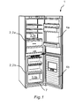
- the Fig. 1 shows as an example of a refrigerator, a household refrigerator 1 in the design of aissergefrierkombination.
- the household refrigerator 1 has at least one heat-insulated inner container 2, in the illustrated embodiment, two heat-insulated inner container 2a, 2b.
- An upper heat-insulated inner container 2a forms a cooling space 3a as a cold room 3 for storing refrigerated goods above zero degrees Celsius, in particular between zero degrees and plus eight degrees Celsius.
- the upper heat-insulated inner container 2a is closed by a first door leaf 4a.
- a lower heat-insulated inner container 2b forms a freezer compartment 3b as a cold room 3 for storing refrigerated goods below zero degrees Celsius, in particular at about minus 18 degrees Celsius.
- the lower heat-insulated inner container 2b is closed by a second door leaf 4b.
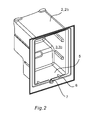
- the Fig. 2 shows the example of the lower heat-insulated inner container 2b of the freezer compartment 3b of theissergefrierkombination Fig. 1 a bottom wall 5 formed by a part of the heat-insulated inner container 2b.
- a bottom wall 5 formed by a part of the heat-insulated inner container 2b.
- raised dam wall 6 of the inner container 2b an inventive sequence 7 is formed.
- the shape of the drain 7 is in the Fig. 4a to 4c more clearly shown and explained in more detail in connection with these figures.
- a drain line 12 according to the invention is shown integrally in an Eis Swissrungsschale 9 as an example of an accessory of the household refrigerator 1 integrated.
- the ice-making preparation tray 9 shown has a plurality of freezing chambers 10 into which water or another free-flowing liquid can be introduced.
- the freezer compartments 10 are shown from below.
- the freezing chambers 10 have sloping side walls 11, so that frozen pieces of ice can be easily detached from the freezing chambers 10.
- the multiple freezing chambers 10 are interconnected by a frame 12. Frame 14 and the plurality of freezer compartments 10 form the actual Eis Glaschungsschale. 9
- a drain line 12 In a central portion 9a of the Eis Swissrungsschale 9 runs between two left and two right freezers 10, a drain line 12.
- the drain line 12 has a channel-shaped line section 12a and a connecting piece 13.
- the connecting piece 13 in turn has a conduit groove 12b.
- the drain line 12 may be formed by the conduit section 12a extending between two left and two right freezing chambers 10 and the conduit channel 12b formed by the bottom of the connecting piece 13.
- the line section 12a is thus formed by the over the connecting piece 13 also extended part of the conduit groove 12b.
- the channel groove 12b has an arcuate cross-section and extends in the form of an elliptic curve by more than 180 degrees, ie from a curved bottom portion of the conduit groove 12b, two opposite lateral wall portions 15a and 15b extend. Above upper edges of the wall sections 15a and 15b, three open arcuate ribs 16a, 16b, 16c rise on each side.
- the arcuate ribs 16a, 16b, 16c are formed to form an at least substantially conical outer contour of the connecting piece 13. Like in the Fig.
- the ribs 16a, 16b, 16c have an outer edge, which is adapted to the elliptical contour of an inner wall 17 of the drain 7.
- the connecting piece 13 at its free end a further annularly closed, ie circumferential annular rib 16d.
- the inner wall 17 of the drain 7 is also designed widening in the direction of flow, ie, the inner wall 17 is conically shaped.
- the inner wall 17 forms a sealing seat 17a for the connecting piece 13 of the drain line 12th
Landscapes
- Engineering & Computer Science (AREA)
- Chemical & Material Sciences (AREA)
- Combustion & Propulsion (AREA)
- Physics & Mathematics (AREA)
- Mechanical Engineering (AREA)
- Thermal Sciences (AREA)
- General Engineering & Computer Science (AREA)
- Removal Of Water From Condensation And Defrosting (AREA)
Applications Claiming Priority (1)
| Application Number | Priority Date | Filing Date | Title |
|---|---|---|---|
| DE201110002644 DE102011002644A1 (de) | 2011-01-13 | 2011-01-13 | Kältegerät mit einem Tauwasserablauf |
Publications (2)
| Publication Number | Publication Date |
|---|---|
| EP2476980A2 true EP2476980A2 (fr) | 2012-07-18 |
| EP2476980A3 EP2476980A3 (fr) | 2013-07-31 |
Family
ID=45495679
Family Applications (1)
| Application Number | Title | Priority Date | Filing Date |
|---|---|---|---|
| EP11195763.5A Withdrawn EP2476980A3 (fr) | 2011-01-13 | 2011-12-27 | Appareil frigorifique doté d'un écoulement d'eau de condensation |
Country Status (2)
| Country | Link |
|---|---|
| EP (1) | EP2476980A3 (fr) |
| DE (1) | DE102011002644A1 (fr) |
Citations (1)
| Publication number | Priority date | Publication date | Assignee | Title |
|---|---|---|---|---|
| DE102004045477A1 (de) | 2004-09-20 | 2006-03-30 | BSH Bosch und Siemens Hausgeräte GmbH | Kältegerät mit Wasserablauf |
Family Cites Families (3)
| Publication number | Priority date | Publication date | Assignee | Title |
|---|---|---|---|---|
| SE402346B (sv) * | 1975-08-29 | 1978-06-26 | Electrolux Ab | Anordning vid ett frysskap for avledning av smeltvatten vid avfrostning |
| DE8436339U1 (de) * | 1984-12-12 | 1986-04-10 | Licentia Patent-Verwaltungs-Gmbh, 6000 Frankfurt | Tauwasserablauf für ein Kühlgerät |
| DE4304501A1 (de) * | 1993-02-15 | 1994-08-18 | Bosch Siemens Hausgeraete | Kühl- oder Gefriergerät mit einem wärmeisolierenden Gehäuse |
-
2011
- 2011-01-13 DE DE201110002644 patent/DE102011002644A1/de not_active Withdrawn
- 2011-12-27 EP EP11195763.5A patent/EP2476980A3/fr not_active Withdrawn
Patent Citations (1)
| Publication number | Priority date | Publication date | Assignee | Title |
|---|---|---|---|---|
| DE102004045477A1 (de) | 2004-09-20 | 2006-03-30 | BSH Bosch und Siemens Hausgeräte GmbH | Kältegerät mit Wasserablauf |
Also Published As
| Publication number | Publication date |
|---|---|
| EP2476980A3 (fr) | 2013-07-31 |
| DE102011002644A1 (de) | 2012-07-19 |
Similar Documents
| Publication | Publication Date | Title |
|---|---|---|
| EP2059736A1 (fr) | Appareil réfrigérant comprenant une ouverture à compensation de pression | |
| EP2494283A2 (fr) | Appareil frigorifique et machine à glaçons associée | |
| EP2561292B1 (fr) | Vantail de porte, procédé de fabrication d'un vantail de porte et appareil frigorifique équipé d'un vantail de porte | |
| DE102008054417A1 (de) | Kältegerät, insbesondere Haushaltsgefrierschrank | |
| WO2008025636A2 (fr) | Appareil ménager comportant un écoulement d'eau | |
| DE102006040381A1 (de) | Kältegerät mit Druckausgleichsventil | |
| DE102015203147A1 (de) | Kältegerät mit Rahmenheizung | |
| EP2318789A1 (fr) | Réfrigérateur avec appareil à glaçons | |
| EP2087300B1 (fr) | Distributeur de glace et volet approprié | |
| EP2467656B1 (fr) | Réfrigérateur avec canal d'eau de décongélation et siphon | |
| DE102011002644A1 (de) | Kältegerät mit einem Tauwasserablauf | |
| EP2433062B1 (fr) | Boîtier d'appareil frigorifique comportant un passage d'équilibrage de pression | |
| WO2008025696A2 (fr) | Appareil réfrigérant présentant des fixations pour un support de denrées à réfrigérer | |
| EP2193733A1 (fr) | Machine de préparation de boissons ainsi que récipient de lait correspondant | |
| WO2011131443A2 (fr) | Vantail de porte, procédé de fabrication d'un vantail de porte et appareil frigorifique équipé d'un vantail de porte | |
| WO2006120088A1 (fr) | Dispositif de refroidissement | |
| DE2638568C3 (de) | Anordnung zum Ableiten von Wasser aus dem Innenraum eines Kühl- oder Gefrierschranks | |
| EP2494285A2 (fr) | Appareil frigorifique equipe d'une machine a glaçons | |
| DE102009003265B4 (de) | Kältegerät mit Druckausgleichsdurchgang | |
| DE102018122904A1 (de) | Gefriertruhe, insbesondere für Eiscreme-Produkte | |
| DE202005014380U1 (de) | Kältegerät mit Wasserablauf | |
| EP2741033A2 (fr) | Appareil frigorifique doté d'un écoulement d'eau de condensation | |
| WO2011131455A2 (fr) | Vantail de porte et appareil frigorifique équipé d'un vantail de porte | |
| EP2746704B1 (fr) | Appareil frigorifique ménager doté d'une fente d'aération non rectiligne entre une porte d'un compartiment de congélation et une porte d'un compartiment de réfrigération adjacent | |
| WO2007062919A1 (fr) | Porte pour un appareil refrigerant |
Legal Events
| Date | Code | Title | Description |
|---|---|---|---|
| PUAI | Public reference made under article 153(3) epc to a published international application that has entered the european phase |
Free format text: ORIGINAL CODE: 0009012 |
|
| AK | Designated contracting states |
Kind code of ref document: A2 Designated state(s): AL AT BE BG CH CY CZ DE DK EE ES FI FR GB GR HR HU IE IS IT LI LT LU LV MC MK MT NL NO PL PT RO RS SE SI SK SM TR |
|
| AX | Request for extension of the european patent |
Extension state: BA ME |
|
| PUAL | Search report despatched |
Free format text: ORIGINAL CODE: 0009013 |
|
| AK | Designated contracting states |
Kind code of ref document: A3 Designated state(s): AL AT BE BG CH CY CZ DE DK EE ES FI FR GB GR HR HU IE IS IT LI LT LU LV MC MK MT NL NO PL PT RO RS SE SI SK SM TR |
|
| AX | Request for extension of the european patent |
Extension state: BA ME |
|
| RIC1 | Information provided on ipc code assigned before grant |
Ipc: F25D 21/14 20060101AFI20130624BHEP |
|
| 17P | Request for examination filed |
Effective date: 20140131 |
|
| RBV | Designated contracting states (corrected) |
Designated state(s): AL AT BE BG CH CY CZ DE DK EE ES FI FR GB GR HR HU IE IS IT LI LT LU LV MC MK MT NL NO PL PT RO RS SE SI SK SM TR |
|
| RAP1 | Party data changed (applicant data changed or rights of an application transferred) |
Owner name: BSH HAUSGERAETE GMBH |
|
| GRAP | Despatch of communication of intention to grant a patent |
Free format text: ORIGINAL CODE: EPIDOSNIGR1 |
|
| INTG | Intention to grant announced |
Effective date: 20181130 |
|
| STAA | Information on the status of an ep patent application or granted ep patent |
Free format text: STATUS: THE APPLICATION IS DEEMED TO BE WITHDRAWN |
|
| 18D | Application deemed to be withdrawn |
Effective date: 20190411 |