EP2477053A1 - Optisches objektivsystem - Google Patents
Optisches objektivsystem Download PDFInfo
- Publication number
- EP2477053A1 EP2477053A1 EP10835852A EP10835852A EP2477053A1 EP 2477053 A1 EP2477053 A1 EP 2477053A1 EP 10835852 A EP10835852 A EP 10835852A EP 10835852 A EP10835852 A EP 10835852A EP 2477053 A1 EP2477053 A1 EP 2477053A1
- Authority
- EP
- European Patent Office
- Prior art keywords
- lens
- group
- optical system
- objective optical
- positive
- Prior art date
- Legal status (The legal status is an assumption and is not a legal conclusion. Google has not performed a legal analysis and makes no representation as to the accuracy of the status listed.)
- Granted
Links
Images






Classifications
-
- G—PHYSICS
- G02—OPTICS
- G02B—OPTICAL ELEMENTS, SYSTEMS OR APPARATUS
- G02B13/00—Optical objectives specially designed for the purposes specified below
- G02B13/001—Miniaturised objectives for electronic devices, e.g. portable telephones, webcams, PDAs, small digital cameras
-
- G—PHYSICS
- G02—OPTICS
- G02B—OPTICAL ELEMENTS, SYSTEMS OR APPARATUS
- G02B23/00—Telescopes, e.g. binoculars; Periscopes; Instruments for viewing the inside of hollow bodies; Viewfinders; Optical aiming or sighting devices
- G02B23/24—Instruments or systems for viewing the inside of hollow bodies, e.g. fibrescopes
- G02B23/2407—Optical details
- G02B23/2423—Optical details of the distal end
- G02B23/243—Objectives for endoscopes
Definitions
- the present invention relates to an objective optical system having a focusing function, and in particular, to an endoscope objective lens capable of near observation and an image-capturing lens for consumer compact cameras and so on.
- a known objective optical system that aims at increasing the depth reduces the focal length while maintaining the same angle of view by using a first lens having a meniscus shape to prevent the occurrence of distortion (for example, see Patent Literature 1).
- Known objective lenses having a focusing function are constituted by two groups, that is, negative and positive groups, two positive groups, or three groups, that is, negative, positive, and positive groups, respectively, and achieve focusing by moving the second group (for example, see Patent Literatures 2 to 4).
- magnifying endoscope objective lenses capable of focusing on a nearer object point are constituted by three groups, that is, positive, negative, and positive groups, in which the negative second group moves to achieve focusing (for example, see Patent Literatures 4 to 6).
- Another known type of objective lens is constituted by three groups, that is, negative, positive, and negative groups, in which the positive second group moves to achieve focusing (for example, see Patent Literature 7).
- the objective lens disclosed in Patent Literature 1 is configured such that the first concave lens has a meniscus shape, and thus, the lens protrudes at the distal end of the endoscope. Therefore, it has the problem of insufficient water break during observation and the problem that scratches tend to occur more frequently at the distal end lens due to impacts or the like.
- the endoscope objective lenses disclosed in Patent Literatures 2 and 3 cannot be said to have wide angles of view because the field of view during observation is narrow. This therefore makes it difficult to perform operations, such as screening the interior of a living organism to find a lesion and treating a lesion, thus posing a practical problem.
- the objective lens disclosed in Patent Literature 4 has insufficient performance because the image plane fluctuates considerably during focusing.
- Patent Literatures 5 to 8 Since the optical systems disclosed in Patent Literatures 5 to 8 have a wide object point range in which focusing is possible, thus allowing observation at a nearer location, the magnification during the nearest observation is large, which is therefore suitable for magnified observation. However, there is a large change in the angle of view during focusing; that is, it is wide during ordinary observation of a far object point but becomes extremely narrow during near observation. Accordingly, using them as general endoscope objective lenses causes difficulty in operations, such as screening, biopsy, and treatment of a lesion. Furthermore, Patent Literatures 2, 4, and 6 disclose objective optical systems in which the first lens is formed in a meniscus shape to increase the depth; however, they are not desirable in terms of layout, similarly to Patent Literature 1.
- the present invention has been made in consideration of the above circumstances, and an object thereof is to provide, in an objective optical system in which focusing can be achieved according to a change in object point distance, a high-performance objective optical system in which distortion hardly occurs and which is compatible with a high-pixel-count image acquisition device.
- a first aspect of the present invention is an objective optical system comprising, in order from an object side, a first group, a second group, and a third group, wherein the first group includes, in order from the object side, a plano-concave lens and a meniscus lens whose convex surface is towards an image side; and the second group has positive power and moves in a direction of an optical axis to perform focusing.
- a moving lens group for focusing may be any of the plurality of constituent groups.
- using the second group disposed near an aperture stop as the moving lens group can reduce the lens diameter, thereby decreasing the load on a driving mechanism.
- the moving lens group may be one or a plurality of groups; however, using only one group has the merit of simplifying the mechanical structure.
- the objective optical system according to the first aspect of the present invention can achieve a focusing mechanism provided that the group configuration includes two or more groups. If the objective optical system is constituted by only two groups, fluctuation of the image plane during focusing tends to increase. In this case, there is no problem if the object point range in which focusing is possible is narrow. However, the group configuration needs to have three or more groups in consideration of focusing in a somewhat wide object point range. The three-group configuration can achieve a high-performance objective optical system that is sufficiently compatible with a high-pixel-count image acquisition device.
- the first group is constituted by a plano-concave lens disposed on the object side and a meniscus lens whose convex surface is towards the image side.
- the focal length must be decreased. This absolutely needs correction of distortion.
- the first lens is a plano-concave lens whose lens surface does not protrude to facilitate water breaking during observation and to resist scratches or the like on the outer surface. However, this makes it impossible to form the first lens in the shape of a concave meniscus lens to correct distortion.
- the lens for distortion correction is preferably disposed in the vicinity of the first lens.
- the use of a meniscus lens with an optimum shape, that is, a lens whose convex surface is towards the image side, as the second lens, as in the first aspect of the present invention, can offer a distortion correction effect.
- the first group has negative power; and the third group has positive power.
- the first group is a negative group, and the third group is a positive group.
- the second group includes a positive meniscus lens whose convex surface is towards the object side; and the third group includes a first positive lens and a joined lens composed of a second positive lens and a negative lens.
- the second group which is a moving group
- the moving group is a positive group. If the moving group is a negative group, the change in the position of an entrance pupil is large, causing a corresponding large change in the angle of view, which is undesirable.
- the moving lens is a positive meniscus lens whose convex surface is towards the object side. This shape can reduce image plane fluctuations during focusing.
- the third group is constituted by a first positive lens and a joined lens composed of a second positive lens and a negative lens.
- the first positive lens mainly contributes to image formation.
- the joined lens composed of the second positive lens and the negative lens takes on a chromatic aberration correcting action.
- Conditional Expressions (1) and (2) are satisfied: f / f ⁇ 2 ⁇ 0.12 0.92 ⁇ f / IH ⁇ 1.08 where f is a focal length of an entire system during far-point observation, f2 is a focal length of the meniscus lens, and IH is an image height.
- the meniscus lens serving as the second lens is a positive lens or a negative lens not having high power and correcting high-degree distortion.
- Exceeding the range of Conditional Expression (1) causes a large field curvature and also reduces the distortion correction effect, which is not desirable.
- Conditional Expression (2) is a conditional expression for limiting the ratio of a focal length to an image height. If a comparison is made at a fixed angle of view, the focal length relative to the image height is small provided that the value is within the range of Conditional Expression (2), which therefore increases the effect of increasing the depth. If the value falls below the lower limit of Conditional Expression (2), the focal length becomes too small, and thus, the magnification at the center of the screen is decreased, which makes it difficult to observe a lesion. If the value exceeds the upper limit of Conditional Expression (2), the focal length increases, which decreases the effect of increasing the depth, which is not desirable.
- a second aspect of the present invention is an objective optical system comprising, in order from an object side, a plano-concave lens, a meniscus lens whose convex surface is towards an image side, an aperture stop, a first positive lens having convex surfaces at both sides, and a joined lens composed of a second positive lens and a negative lens, and satisfying the following Conditional Expression (3): 0.08 ⁇ d / f ⁇ 0.32 where d is an air gap between the meniscus lens and the first positive lens.
- Conditional Expression (3) is a conditional expression for decreasing the field curvature. If the value falls below the lower limit of Conditional Expression (3), the meridional image plane is inclined over, and if the value exceeds the upper limit of Conditional Expression (3), the meridional image plane is inclined under, respectively. Accordingly, this causes degradation of a peripheral image in terms of performance, which is not desirable.
- a high-performance objective optical system which is compatible with a high-pixel-count image acquisition device and which is capable of focusing depending on a change in object point distance and having sufficient depths of field at individual object point distances can be provided.
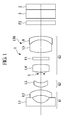
- an objective optical system 1 is constituted by, in order from the object side, a first group G1 having negative refractive power, a second group G2 having positive refractive power, and a third group G3 having positive refractive power.
- the first group G1 is constituted by, in order from the object side, a first lens L1, which is a negative lens, and a second lens L2, which is a positive lens or a negative lens having low power.
- the second group G2 is constituted by a third lens L3, which is a positive lens.
- the second group G2 has a focusing action in an ordinary observation state (see Fig. 1 ) and in a near observation state (see Fig. 2 ) by means of the third lens L3 moving on the optical axis.
- the third group G3 is constituted by, in order from the object side, a fourth lens (first positive lens) L4, which is a positive lens, and a positive joined lens L56 in which a positive lens (second positive lens) L5 and a negative lens L6 are joined.
- first positive lens which is a positive lens
- second positive lens positive lens
- L6 negative lens
- An aperture stop S is disposed between the second group G2 and the third group G3.
- the aperture stop S is fixed in front of the third group G3 during focusing.
- Reference signs F1 and F2 denote parallel flat plates.
- the parallel flat plates F1 and F2 are filters or the like for cutting off light with a specific wavelength, for example, 1060 nm light from a YAG laser, 810 nm light from a semiconductor laser, and light in the near-infrared region.
- the parallel flat plates F1 and F2 are suitably disposed on the optical axis; in the illustrated example, they are disposed between the fourth lens L4 and the joined lens L56 and after the third group G3.
- the objective optical system 1 constitutes an image-capturing optical system together with an image acquisition device (not shown), such as a CCD, disposed in the vicinity of an image plane.
- Reference sign 2 denotes chip-sealing glass that seals the surface of the image acquisition device.
- Reference sign 3 denotes an optical element, such as a cover glass.
- the objective optical system 1 satisfies the following Conditional Expressions (1) and (2): f / f ⁇ 2 ⁇ 0.12 092 ⁇ f / IH ⁇ 1.08 where f is the focal length of the entire system during far-point observation, f2 is the focal length of the second lens L2, and IH is the image height.
- the objective optical system 1 also satisfies the following Conditional Expression (3): 0.08 ⁇ d / f ⁇ 0.32 where d is the air gap between the second lens L2 and the third lens L3. More preferably, the objective optical system 1 satisfies the following Conditional Expression (3)': 0.12 ⁇ d / f ⁇ 0.24
- the configuration can be made compact while preventing degradation of image quality due to distortion. Furthermore, by constituting the image-capturing optical system in combination with a high-pixel-count image acquisition device, high-definition images can be obtained at individual object points.
- Conditional Expression (4) is for the angle of view. If the value falls below the lower limit of Conditional Expression (4), the observation field of view decreases, causing frequent overlooking of lesions, which is undesirable. On the other hand, if the value exceeds the upper limit of Conditional Expression (4), the field of view can be ensured, but the error sensitivity of the image-side surface of the first lens L1 with respect to the angle of view becomes high, and thus, vignetting tends to occur due to manufacturing errors, which is undesirable.
- Conditional Expression (5) is for the amount of movement of the third lens L3, which serves as a moving lens. If the value falls below the lower limit of Conditional Expression (5), the power of the third lens L3 increases, and thus, using a positive meniscus lens whose convex surface is towards the object side also increases field curvature changes during focusing. On the other hand, if the value exceeds the upper limit of Conditional Expression (5), the power of the third lens L3 decreases, and thus, the amount of lens movement increases, which increases the size of the mechanical driving system, which is undesirable.
- the above embodiment satisfies the following Conditional Expression (6): 1.2 ⁇ f ⁇ 4 / f ⁇ 2.6 where f4 is the focal length of the fourth lens L4.
- the fourth lens L4 plays the role of forming an image on an imaging plane. If the value falls below the lower limit of Conditional Expression (6), sufficient back focusing cannot be ensured. This makes it impossible to ensure a sufficient amount of adjustment of the image capturing position, performed behind the last lens L6, due to manufacturing errors of the objective optical system 1, which is undesirable. On the other hand, if the value exceeds the upper limit of Conditional Expression (6), the spherical aberration during near observation becomes under-corrected, which makes it impossible to obtain sufficient resolution.
- Conditional Expression (7) is mainly for correction of axial chromatic aberration. If the value falls below the lower limit of Conditional Expression (7), the C-line and the F-line increase, over and under, respectively, which is not desirable. On the other hand, if the value exceeds the upper limit of Conditional Expression (7), the C-line and the F-line increase, under and over, respectively, which is not desirable.
- Conditional Expression (8) is mainly for magnification chromatic aberration. If the value falls below the lower limit of Conditional Expression (8), the C-line and the F-line increase, over and under, respectively, which is not desirable. On the other hand, if the value exceeds the upper limit of Conditional Expression (8), the C-line and the F-line increase, under and over, respectively, which causes a color blur, thus causing degradation of the peripheral resolution.
- the above embodiment satisfies the following Conditional Expression (9): 6 ⁇ LTL / f ⁇ 8 where LTL is the total length of the lens system. If the value falls below the lower limit of Conditional Expression (9), the lens total length becomes too short so that it becomes difficult to ensure a desired number of lenses. On the other hand, if the value exceeds the upper limit of Conditional Expression (9), the lens system, including the lens barrel part for holding the lenses, is increased in size, which makes it difficult to locate it at the distal end of the endoscope.
- Conditional Expression (10) is for the observation angle of view during focusing. It is preferable that the angle of view changes as little as possible during focusing. If the change in angle of view increases, a change in field of view becomes noticeable during focusing. This results in a view like that in electronic magnification, which is not desirable. If the change in angle of view is within the range of Conditional Expression (10), the operator can perform focusing without a noticeable difference without recognition that the observation range has changed greatly.
- Conditional Expression (10) If the value falls below the lower limit of Conditional Expression (10) during focusing while the position of the object is changed from a far object point to a near object point, a blurred image is focused on, and the object is viewed as if it is magnified, which is not desirable. On the other hand, if the value exceeds the upper limit of Conditional Expression (10), the object is viewed as if it is reduced, which is not desirable. Furthermore, this decreases the depth of focus during far observation, thus impairing the ease of use during observation for screening and so on.
- the above embodiment satisfies the following Conditional Expression (10)': 0.9 ⁇ ⁇ n / ⁇ f ⁇ 1.1 Since the change in angle of view is further reduced within the range of Conditional Expression (10)', the effects of Conditional Expression (10) can be further increased.
- Conditional Expression (11) is an expression that limits the half angle of view, which is the field of view. To reduce the risk of overlooking a lesion in screening a living organism, it is preferable that it is as wide as possible; a viewing angle of 120° or more is needed at the minimum in the entire object point area. More preferably, the following Conditional Expression (11)' is satisfied, and the field of view is 140° or more: ⁇ f ⁇ 70
- r denotes the radius of curvature of a lens surface
- d denotes the distance between lens surfaces
- numbers following r or d denote surface numbers.
- the units of the radius of curvature and the distance between surfaces are mm.
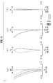
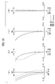
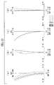
- aberration diagrams (a) shows spherical aberration, (b) shows astigmatism, (c) shows distortion, and (d) shows magnification chromatic aberration.
- Fig. 3 shows an ordinary observation state (far object point)
- Fig. 4 shows a near observation state (near object point).
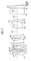
- the objective optical system according to this example is configured such that a first group is constituted by, in order from the object side, a negative lens and a positive lens having low power; a second group is constituted by a positive lens; and a third group is constituted by, in order from the object side, a positive lens, a parallel flat plate, and a positive joined lens in which a positive lens and a negative lens are joined. At the back of the third group, a parallel flat plate is disposed.
- Fig. 7 shows an ordinary observation state (far object point)
- Fig. 8 shows a near observation state (near object point).
- the objective optical system of this embodiment is configured such that a first group is constituted by, in order from the object side, a negative lens, a parallel flat plate, and a negative lens having low power; a second group is constituted by a positive lens; and a third group is constituted by, in order from the object side, a positive lens and a positive joined lens in which a positive lens and a negative lens are joined.
- Table 2 shows aberration diagrams of the individual states.
- Lens Data Surface number Radius of curvature Distance between surfaces Refractive index Ne Abbe number ⁇ d 1 ⁇ 0.38 1.88815 40.76 2 1.305 0.53 3 ⁇ 0.31 1.51564 75.00 4 ⁇ 0.19 5 -5.306 0.56 1.77621 49.60 6 -5.895 D6 7 1.560 0.48 1.59143 61.14 8 1.724 D8 9
- Aperture stop 0.20 10 3.903 0.60 1.77621 49.60 11 -6.293 1.64 12 3.748 1.67 1.48915 70.23 13 -1.860 0.39 1.93430 14 -4.120 1.37 15 ⁇ 1.37 1.52498 59.89 16 ⁇ 0.64 1.50801 60.00 17 Imaging plane
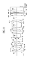
- Fig. 11 shows an ordinary observation state (far object point)
- Fig. 12 shows a near observation state (near object point).
- the objective optical system according to this example is configured such that a first group is constituted by, in order from the object side, a negative lens and a negative lens having low power; a second group is constituted by a positive lens; and a third group is constituted by, in order from the object side, a positive lens, a parallel flat plate, and a positive joined lens in which the positive lens and the negative lens are joined. At the back of the third group, a parallel flat plate is disposed.
- Table 3 The values of varying parameters of the thus-configured objective optical system in two states, that is, the ordinary observation state and the near observation state, are shown in Table 3, and aberration diagrams of the individual states are shown in Figs. 13 and 14 .
- Table 4 shows the values of Conditional Expressions (1) to (11) in the objective optical system according to Examples 1 to 3.
- Example 2 Example 3 (1) 0.08 0.01 0.06 (2) 1.00 0.97 0.99 (3) 0.20 0.14 0.20 (4) -0.78 -0.89 -0.81 (5) 6.48 8.00 5.48 (6) 2.13 1.92 1.70 (7) 0.71 0.71 0.80 (8) 1.13 1.11 1.11 (9) 6.86 7.03 6.82 (10) 0.99 0.94 0.98 (11) 72.2 81.3 73.8
- ⁇ Notes ⁇ Inventions with the following configurations are derived from the examples.
- ⁇ Note 1 ⁇ An objective optical system comprising, in order from an object side, a first group, a second group, and a third group, wherein the first group includes, in order from the object side, a plano-concave lens and a meniscus lens whose convex surface is towards an image side; and the second group has positive power and moves in the direction of an optical axis to perform focusing.
- An objective optical system comprising, in order from an object side, a plano-concave lens, a meniscus lens whose convex surface is towards an image side, an aperture stop, a first positive lens having convex surfaces at both sides, and a joined lens composed of a second positive lens and a negative lens, and satisfying the following Conditional Expression (3): 0.08 ⁇ d / f ⁇ 032 where d is the air gap between the meniscus lens and the first positive lens.
Landscapes
- Physics & Mathematics (AREA)
- General Physics & Mathematics (AREA)
- Optics & Photonics (AREA)
- Astronomy & Astrophysics (AREA)
- Lenses (AREA)
Applications Claiming Priority (2)
| Application Number | Priority Date | Filing Date | Title |
|---|---|---|---|
| JP2009282205 | 2009-12-11 | ||
| PCT/JP2010/071213 WO2011070930A1 (ja) | 2009-12-11 | 2010-11-29 | 対物光学系 |
Publications (3)
| Publication Number | Publication Date |
|---|---|
| EP2477053A1 true EP2477053A1 (de) | 2012-07-18 |
| EP2477053A4 EP2477053A4 (de) | 2013-07-10 |
| EP2477053B1 EP2477053B1 (de) | 2019-06-19 |
Family
ID=44145475
Family Applications (1)
| Application Number | Title | Priority Date | Filing Date |
|---|---|---|---|
| EP10835852.4A Not-in-force EP2477053B1 (de) | 2009-12-11 | 2010-11-29 | Optisches objektivsystem für ein endoskop |
Country Status (5)
| Country | Link |
|---|---|
| US (1) | US8456767B2 (de) |
| EP (1) | EP2477053B1 (de) |
| JP (1) | JP4934233B2 (de) |
| CN (1) | CN102687053B (de) |
| WO (1) | WO2011070930A1 (de) |
Cited By (4)
| Publication number | Priority date | Publication date | Assignee | Title |
|---|---|---|---|---|
| EP2960701A4 (de) * | 2013-02-22 | 2016-09-21 | Olympus Corp | Optisches system für ein endoskopobjektiv und bildgebungsvorrichtung |
| US9817226B2 (en) | 2014-09-22 | 2017-11-14 | Olympus Corporation | Endoscope objective optical system |
| EP3159725A4 (de) * | 2014-06-20 | 2018-02-14 | Olympus Corporation | Optisches objektivsystem für ein endoskop |
| US10268026B2 (en) | 2012-02-28 | 2019-04-23 | Nikon Corporation | Optical system, optical apparatus and method for manufacturing the optical system |
Families Citing this family (88)
| Publication number | Priority date | Publication date | Assignee | Title |
|---|---|---|---|---|
| US9872609B2 (en) | 2009-06-18 | 2018-01-23 | Endochoice Innovation Center Ltd. | Multi-camera endoscope |
| EP2442706B1 (de) | 2009-06-18 | 2014-11-12 | EndoChoice Innovation Center Ltd. | Mehrkamera-endoskop |
| US9901244B2 (en) | 2009-06-18 | 2018-02-27 | Endochoice, Inc. | Circuit board assembly of a multiple viewing elements endoscope |
| US9101268B2 (en) | 2009-06-18 | 2015-08-11 | Endochoice Innovation Center Ltd. | Multi-camera endoscope |
| US10165929B2 (en) | 2009-06-18 | 2019-01-01 | Endochoice, Inc. | Compact multi-viewing element endoscope system |
| US11864734B2 (en) | 2009-06-18 | 2024-01-09 | Endochoice, Inc. | Multi-camera endoscope |
| US10130246B2 (en) | 2009-06-18 | 2018-11-20 | Endochoice, Inc. | Systems and methods for regulating temperature and illumination intensity at the distal tip of an endoscope |
| US9642513B2 (en) | 2009-06-18 | 2017-05-09 | Endochoice Inc. | Compact multi-viewing element endoscope system |
| US10524645B2 (en) | 2009-06-18 | 2020-01-07 | Endochoice, Inc. | Method and system for eliminating image motion blur in a multiple viewing elements endoscope |
| US11278190B2 (en) | 2009-06-18 | 2022-03-22 | Endochoice, Inc. | Multi-viewing element endoscope |
| US9474440B2 (en) | 2009-06-18 | 2016-10-25 | Endochoice, Inc. | Endoscope tip position visual indicator and heat management system |
| US11547275B2 (en) | 2009-06-18 | 2023-01-10 | Endochoice, Inc. | Compact multi-viewing element endoscope system |
| US12137873B2 (en) | 2009-06-18 | 2024-11-12 | Endochoice, Inc. | Compact multi-viewing element endoscope system |
| US9492063B2 (en) | 2009-06-18 | 2016-11-15 | Endochoice Innovation Center Ltd. | Multi-viewing element endoscope |
| WO2012077116A1 (en) | 2010-12-09 | 2012-06-14 | Peermedical Ltd. | Flexible electronic circuit board for a multi-camera endoscope |
| US8926502B2 (en) | 2011-03-07 | 2015-01-06 | Endochoice, Inc. | Multi camera endoscope having a side service channel |
| US9101287B2 (en) | 2011-03-07 | 2015-08-11 | Endochoice Innovation Center Ltd. | Multi camera endoscope assembly having multiple working channels |
| US9713417B2 (en) | 2009-06-18 | 2017-07-25 | Endochoice, Inc. | Image capture assembly for use in a multi-viewing elements endoscope |
| US9402533B2 (en) | 2011-03-07 | 2016-08-02 | Endochoice Innovation Center Ltd. | Endoscope circuit board assembly |
| US9706903B2 (en) | 2009-06-18 | 2017-07-18 | Endochoice, Inc. | Multiple viewing elements endoscope system with modular imaging units |
| US12220105B2 (en) | 2010-06-16 | 2025-02-11 | Endochoice, Inc. | Circuit board assembly of a multiple viewing elements endoscope |
| US9560953B2 (en) | 2010-09-20 | 2017-02-07 | Endochoice, Inc. | Operational interface in a multi-viewing element endoscope |
| EP4233680B1 (de) | 2010-09-20 | 2025-06-18 | EndoChoice, Inc. | Distaler endoskopabschnitt umfassend eine einheitliche flüssigkeitskanal-komponente |
| US9706908B2 (en) | 2010-10-28 | 2017-07-18 | Endochoice, Inc. | Image capture and video processing systems and methods for multiple viewing element endoscopes |
| EP2635932B1 (de) * | 2010-10-28 | 2019-06-05 | EndoChoice Innovation Center Ltd. | Optische systeme für multi-sensor-endoskope |
| US10663714B2 (en) | 2010-10-28 | 2020-05-26 | Endochoice, Inc. | Optical system for an endoscope |
| US12204087B2 (en) | 2010-10-28 | 2025-01-21 | Endochoice, Inc. | Optical systems for multi-sensor endoscopes |
| US11889986B2 (en) | 2010-12-09 | 2024-02-06 | Endochoice, Inc. | Flexible electronic circuit board for a multi-camera endoscope |
| EP3420886B8 (de) | 2010-12-09 | 2020-07-15 | EndoChoice, Inc. | Multikameraendoskop mit flexibler elektronischer leiterplatte |
| US10517464B2 (en) | 2011-02-07 | 2019-12-31 | Endochoice, Inc. | Multi-element cover for a multi-camera endoscope |
| CN103491854B (zh) | 2011-02-07 | 2016-08-24 | 恩多卓斯创新中心有限公司 | 用于多摄影机内窥镜的多元件罩 |
| EP2648026B1 (de) | 2011-06-23 | 2017-09-27 | Olympus Corporation | Optisches objektivsystem für ein endoskop |
| US9456735B2 (en) * | 2012-09-27 | 2016-10-04 | Shahinian Karnig Hrayr | Multi-angle rear-viewing endoscope and method of operation thereof |
| CA2798729A1 (en) | 2011-12-13 | 2013-06-13 | Peermedical Ltd. | Rotatable connector for an endoscope |
| CA2798716A1 (en) | 2011-12-13 | 2013-06-13 | Endochoice Innovation Center Ltd. | Removable tip endoscope |
| JP5903937B2 (ja) * | 2012-03-07 | 2016-04-13 | 株式会社ニコン | 光学系、光学機器及び光学系の製造方法 |
| JP5903932B2 (ja) * | 2012-02-28 | 2016-04-13 | 株式会社ニコン | 光学系、光学機器及び光学系の製造方法 |
| US9560954B2 (en) | 2012-07-24 | 2017-02-07 | Endochoice, Inc. | Connector for use with endoscope |
| WO2014088104A1 (ja) * | 2012-12-07 | 2014-06-12 | オリンパス株式会社 | 対物レンズ及びそれを備えた観察装置 |
| CN104937470B (zh) * | 2013-02-28 | 2017-03-08 | 奥林巴斯株式会社 | 物镜光学系统 |
| US9993142B2 (en) | 2013-03-28 | 2018-06-12 | Endochoice, Inc. | Fluid distribution device for a multiple viewing elements endoscope |
| US9986899B2 (en) | 2013-03-28 | 2018-06-05 | Endochoice, Inc. | Manifold for a multiple viewing elements endoscope |
| US10595714B2 (en) | 2013-03-28 | 2020-03-24 | Endochoice, Inc. | Multi-jet controller for an endoscope |
| US9636003B2 (en) | 2013-06-28 | 2017-05-02 | Endochoice, Inc. | Multi-jet distributor for an endoscope |
| US12207796B2 (en) | 2013-03-28 | 2025-01-28 | Endochoice Inc. | Multi-jet controller for an endoscope |
| JP6204676B2 (ja) * | 2013-03-29 | 2017-09-27 | キヤノン株式会社 | 撮像レンズ及びそれを有する撮像装置 |
| US9667935B2 (en) | 2013-05-07 | 2017-05-30 | Endochoice, Inc. | White balance enclosure for use with a multi-viewing elements endoscope |
| US10499794B2 (en) | 2013-05-09 | 2019-12-10 | Endochoice, Inc. | Operational interface in a multi-viewing element endoscope |
| US9949623B2 (en) | 2013-05-17 | 2018-04-24 | Endochoice, Inc. | Endoscope control unit with braking system |
| US10064541B2 (en) | 2013-08-12 | 2018-09-04 | Endochoice, Inc. | Endoscope connector cover detection and warning system |
| US9943218B2 (en) | 2013-10-01 | 2018-04-17 | Endochoice, Inc. | Endoscope having a supply cable attached thereto |
| US9968242B2 (en) | 2013-12-18 | 2018-05-15 | Endochoice, Inc. | Suction control unit for an endoscope having two working channels |
| WO2015112747A2 (en) | 2014-01-22 | 2015-07-30 | Endochoice, Inc. | Image capture and video processing systems and methods for multiple viewing element endoscopes |
| JP6339852B2 (ja) * | 2014-05-01 | 2018-06-06 | キヤノン株式会社 | ズームレンズ及びそれを有する撮像装置 |
| US11234581B2 (en) | 2014-05-02 | 2022-02-01 | Endochoice, Inc. | Elevator for directing medical tool |
| WO2016014581A1 (en) | 2014-07-21 | 2016-01-28 | Endochoice, Inc. | Multi-focal, multi-camera endoscope systems |
| CN105899993B (zh) * | 2014-08-28 | 2018-09-25 | 奥林巴斯株式会社 | 内窥镜物镜光学系统 |
| CN111990946A (zh) | 2014-08-29 | 2020-11-27 | 恩多巧爱思股份有限公司 | 改变内窥镜插入管的刚度的系统和方法 |
| KR101691351B1 (ko) * | 2014-10-28 | 2016-12-30 | 주식회사 코렌 | 촬영 렌즈 광학계 |
| WO2016067838A1 (ja) * | 2014-10-30 | 2016-05-06 | オリンパス株式会社 | 内視鏡用対物光学系 |
| EP3235241B1 (de) | 2014-12-18 | 2023-09-06 | EndoChoice, Inc. | System zur verarbeitung von videobildern, die durch ein endoskop mit mehreren sichtelementen erzeugt wurden |
| US10271713B2 (en) | 2015-01-05 | 2019-04-30 | Endochoice, Inc. | Tubed manifold of a multiple viewing elements endoscope |
| US10376181B2 (en) | 2015-02-17 | 2019-08-13 | Endochoice, Inc. | System for detecting the location of an endoscopic device during a medical procedure |
| US12529882B2 (en) | 2015-02-24 | 2026-01-20 | Endochoice, Inc. | Optical system for an endoscope |
| US10078207B2 (en) | 2015-03-18 | 2018-09-18 | Endochoice, Inc. | Systems and methods for image magnification using relative movement between an image sensor and a lens assembly |
| US10401611B2 (en) | 2015-04-27 | 2019-09-03 | Endochoice, Inc. | Endoscope with integrated measurement of distance to objects of interest |
| EP3297515B1 (de) | 2015-05-17 | 2020-07-01 | Endochoice, Inc. | Endoskopische bildverbesserung mit in einem prozessor implementierter kontrastbegrenzter adaptiver histogrammentzerrung |
| JP6109461B1 (ja) * | 2015-06-18 | 2017-04-05 | オリンパス株式会社 | 内視鏡用対物光学系 |
| CN107076967B (zh) * | 2015-09-07 | 2020-09-01 | Hoya株式会社 | 内窥镜用变倍光学系统及内窥镜 |
| US9897779B2 (en) * | 2015-09-30 | 2018-02-20 | Apple Inc. | Camera lens system with three lens components |
| TWI586999B (zh) | 2015-10-23 | 2017-06-11 | 大立光電股份有限公司 | 影像擷取透鏡組、取像裝置及電子裝置 |
| JP6985262B2 (ja) | 2015-10-28 | 2021-12-22 | エンドチョイス インコーポレイテッドEndochoice, Inc. | 患者の体内における内視鏡の位置を追跡するための装置及び方法 |
| CN113425225B (zh) | 2015-11-24 | 2024-09-17 | 安多卓思公司 | 用于内窥镜的一次性空气/水阀和抽吸阀 |
| JP2019507628A (ja) | 2016-02-24 | 2019-03-22 | エンドチョイス インコーポレイテッドEndochoice, Inc. | Cmosセンサを用いた複数ビュー要素内視鏡のための回路基板アセンブリ |
| US10292570B2 (en) | 2016-03-14 | 2019-05-21 | Endochoice, Inc. | System and method for guiding and tracking a region of interest using an endoscope |
| CN108700727A (zh) * | 2016-04-12 | 2018-10-23 | 奥林巴斯株式会社 | 内窥镜用对物光学系统 |
| WO2017179387A1 (ja) | 2016-04-13 | 2017-10-19 | オリンパス株式会社 | 対物光学系 |
| EP4321081A3 (de) | 2016-06-21 | 2024-04-24 | EndoChoice, Inc. | Endoskopsystem mit mehreren verbindungsschnittstellen zur schnittstelle mit verschiedenen videodatensignalquellen |
| JP6279195B1 (ja) | 2016-07-04 | 2018-02-14 | オリンパス株式会社 | 内視鏡光学系 |
| DE112017004856T5 (de) | 2016-09-28 | 2019-06-13 | Olympus Corporation | Endoskop-Objektivoptik |
| TWI622824B (zh) | 2017-01-19 | 2018-05-01 | 大立光電股份有限公司 | 光學影像系統組、取像裝置及電子裝置 |
| JP6800824B2 (ja) * | 2017-09-27 | 2020-12-16 | 富士フイルム株式会社 | 内視鏡用対物光学系および内視鏡 |
| CN111527435B (zh) * | 2018-02-27 | 2022-04-05 | 奥林巴斯株式会社 | 内窥镜用物镜光学系统 |
| CN109856776B (zh) * | 2018-12-27 | 2021-05-04 | 瑞声光学解决方案私人有限公司 | 摄像光学镜头 |
| JP7113783B2 (ja) * | 2019-04-25 | 2022-08-05 | 富士フイルム株式会社 | 内視鏡用対物光学系および内視鏡 |
| JP7693600B2 (ja) * | 2022-03-22 | 2025-06-17 | 京セラ株式会社 | 撮像光学系及び撮像装置 |
| JPWO2024166167A1 (de) * | 2023-02-06 | 2024-08-15 | ||
| US20240337812A1 (en) * | 2023-04-10 | 2024-10-10 | Gopro, Inc. | Adjustable-focus optical assemblies for image capture devices |
Family Cites Families (26)
| Publication number | Priority date | Publication date | Assignee | Title |
|---|---|---|---|---|
| US4059344A (en) | 1974-10-26 | 1977-11-22 | Olympus Optical Co., Ltd. | Retrofocus-type objective for endoscopes |
| JPS5515005B2 (de) * | 1974-10-26 | 1980-04-21 | ||
| JPS592343B2 (ja) | 1978-07-19 | 1984-01-18 | 川崎製鉄株式会社 | 複合めつき被覆層中の金属Al量測定方法 |
| JPS5590928A (en) | 1978-12-29 | 1980-07-10 | Olympus Optical Co Ltd | Endoscope objective lens which performs changing of magnification and focusing simultaneously |
| JPS6144283A (ja) | 1984-08-06 | 1986-03-03 | 井関農機株式会社 | 穀粒乾燥機の熱風温度検出装置 |
| JP2556984B2 (ja) * | 1988-02-05 | 1996-11-27 | オリンパス光学工業株式会社 | 内視鏡 |
| JP2899980B2 (ja) * | 1990-02-02 | 1999-06-02 | オリンパス光学工業株式会社 | 内視鏡用対物光学系 |
| JP3336592B2 (ja) * | 1993-03-31 | 2002-10-21 | 富士写真フイルム株式会社 | 変倍ファインダ |
| JP3349766B2 (ja) | 1993-04-30 | 2002-11-25 | オリンパス光学工業株式会社 | 内視鏡対物光学系 |
| JP3590807B2 (ja) | 1995-03-08 | 2004-11-17 | 株式会社ニコン | ズームレンズ |
| JPH0990213A (ja) * | 1995-09-20 | 1997-04-04 | Casio Comput Co Ltd | 撮影レンズ |
| JPH11316339A (ja) | 1998-03-03 | 1999-11-16 | Olympus Optical Co Ltd | 対物光学系 |
| JP2000162541A (ja) | 1998-11-30 | 2000-06-16 | Sanyo Electric Co Ltd | 採光装置 |
| JP2000330015A (ja) | 1999-03-12 | 2000-11-30 | Fuji Photo Optical Co Ltd | 観察深度可変型の内視鏡用対物レンズ |
| JP2000267002A (ja) | 1999-03-15 | 2000-09-29 | Olympus Optical Co Ltd | 光学系 |
| JP4472130B2 (ja) | 2000-07-14 | 2010-06-02 | オリンパス株式会社 | 内視鏡装置 |
| JP4507594B2 (ja) | 2003-12-26 | 2010-07-21 | 日亜化学工業株式会社 | 半導体発光素子 |
| JP4659645B2 (ja) * | 2006-03-01 | 2011-03-30 | オリンパスメディカルシステムズ株式会社 | 拡大内視鏡光学系 |
| JP4931462B2 (ja) * | 2006-04-18 | 2012-05-16 | 日本電産コパル株式会社 | 撮像レンズ |
| JP2008107391A (ja) | 2006-10-23 | 2008-05-08 | Olympus Medical Systems Corp | 内視鏡対物光学系 |
| JP2009016325A (ja) | 2007-07-06 | 2009-01-22 | Masaya Nagasawa | 電源周波数の倍増 |
| JP2009047722A (ja) | 2007-08-13 | 2009-03-05 | Konica Minolta Opto Inc | 変倍光学系、撮像装置およびデジタル機器 |
| CN201122198Y (zh) * | 2007-11-30 | 2008-09-24 | 今鼎光电股份有限公司 | 光学镜头 |
| JP4920572B2 (ja) | 2007-12-21 | 2012-04-18 | オリンパスメディカルシステムズ株式会社 | 内視鏡用対物レンズ |
| JP4653823B2 (ja) * | 2008-06-06 | 2011-03-16 | オリンパスメディカルシステムズ株式会社 | 対物光学系 |
| JP2009163256A (ja) * | 2009-03-03 | 2009-07-23 | Olympus Corp | 光学系 |
-
2010
- 2010-11-29 CN CN201080046866.6A patent/CN102687053B/zh active Active
- 2010-11-29 JP JP2011536669A patent/JP4934233B2/ja active Active
- 2010-11-29 WO PCT/JP2010/071213 patent/WO2011070930A1/ja not_active Ceased
- 2010-11-29 EP EP10835852.4A patent/EP2477053B1/de not_active Not-in-force
-
2011
- 2011-08-23 US US13/199,257 patent/US8456767B2/en active Active
Cited By (4)
| Publication number | Priority date | Publication date | Assignee | Title |
|---|---|---|---|---|
| US10268026B2 (en) | 2012-02-28 | 2019-04-23 | Nikon Corporation | Optical system, optical apparatus and method for manufacturing the optical system |
| EP2960701A4 (de) * | 2013-02-22 | 2016-09-21 | Olympus Corp | Optisches system für ein endoskopobjektiv und bildgebungsvorrichtung |
| EP3159725A4 (de) * | 2014-06-20 | 2018-02-14 | Olympus Corporation | Optisches objektivsystem für ein endoskop |
| US9817226B2 (en) | 2014-09-22 | 2017-11-14 | Olympus Corporation | Endoscope objective optical system |
Also Published As
| Publication number | Publication date |
|---|---|
| WO2011070930A1 (ja) | 2011-06-16 |
| CN102687053A (zh) | 2012-09-19 |
| US20120057251A1 (en) | 2012-03-08 |
| EP2477053A4 (de) | 2013-07-10 |
| CN102687053B (zh) | 2014-11-05 |
| JP4934233B2 (ja) | 2012-05-16 |
| US8456767B2 (en) | 2013-06-04 |
| JPWO2011070930A1 (ja) | 2013-04-22 |
| EP2477053B1 (de) | 2019-06-19 |
Similar Documents
| Publication | Publication Date | Title |
|---|---|---|
| EP2477053B1 (de) | Optisches objektivsystem für ein endoskop | |
| US8203798B2 (en) | Objective optical system | |
| US8422150B2 (en) | Objective optical system | |
| US10649201B2 (en) | Objective optical system | |
| US10996455B2 (en) | Objective optical system, image pickup apparatus, and endoscope | |
| US10914935B2 (en) | Objective optical system | |
| CN107111111B (zh) | 内窥镜用物镜光学系统 | |
| EP3168668A1 (de) | Optisches objektivsystem | |
| US8824067B2 (en) | Endoscope objective optical system | |
| EP2131225A2 (de) | Objektivsystem | |
| EP2963473A1 (de) | Optisches objektivsystem | |
| US12004715B2 (en) | Objective optical system and endoscope using the same | |
| EP3260903A1 (de) | Endoskopsystem | |
| EP2899580A1 (de) | Linse für endoskopobjektiv | |
| WO2018042797A1 (ja) | 内視鏡対物光学系 | |
| US20190258020A1 (en) | Objective optical system | |
| EP2618196A1 (de) | Optisches objektivsystem für ein endoskop | |
| JP6857572B2 (ja) | 内視鏡用対物光学系 | |
| JPWO2020174561A1 (ja) | 内視鏡用対物光学系及び内視鏡 | |
| US20220026702A1 (en) | Endoscope objective optical system and endoscope |
Legal Events
| Date | Code | Title | Description |
|---|---|---|---|
| PUAI | Public reference made under article 153(3) epc to a published international application that has entered the european phase |
Free format text: ORIGINAL CODE: 0009012 |
|
| 17P | Request for examination filed |
Effective date: 20120316 |
|
| AK | Designated contracting states |
Kind code of ref document: A1 Designated state(s): AL AT BE BG CH CY CZ DE DK EE ES FI FR GB GR HR HU IE IS IT LI LT LU LV MC MK MT NL NO PL PT RO RS SE SI SK SM TR |
|
| DAX | Request for extension of the european patent (deleted) | ||
| A4 | Supplementary search report drawn up and despatched |
Effective date: 20130611 |
|
| RIC1 | Information provided on ipc code assigned before grant |
Ipc: G02B 23/24 20060101ALI20130605BHEP Ipc: G02B 13/04 20060101AFI20130605BHEP Ipc: G02B 13/00 20060101ALI20130605BHEP |
|
| 17Q | First examination report despatched |
Effective date: 20140408 |
|
| RAP1 | Party data changed (applicant data changed or rights of an application transferred) |
Owner name: OLYMPUS CORPORATION |
|
| RAP1 | Party data changed (applicant data changed or rights of an application transferred) |
Owner name: OLYMPUS CORPORATION |
|
| RAP1 | Party data changed (applicant data changed or rights of an application transferred) |
Owner name: OLYMPUS CORPORATION |
|
| RIN1 | Information on inventor provided before grant (corrected) |
Inventor name: TAKATO, HIDEYASU |
|
| GRAP | Despatch of communication of intention to grant a patent |
Free format text: ORIGINAL CODE: EPIDOSNIGR1 |
|
| STAA | Information on the status of an ep patent application or granted ep patent |
Free format text: STATUS: GRANT OF PATENT IS INTENDED |
|
| INTG | Intention to grant announced |
Effective date: 20190219 |
|
| GRAS | Grant fee paid |
Free format text: ORIGINAL CODE: EPIDOSNIGR3 |
|
| GRAA | (expected) grant |
Free format text: ORIGINAL CODE: 0009210 |
|
| STAA | Information on the status of an ep patent application or granted ep patent |
Free format text: STATUS: THE PATENT HAS BEEN GRANTED |
|
| AK | Designated contracting states |
Kind code of ref document: B1 Designated state(s): AL AT BE BG CH CY CZ DE DK EE ES FI FR GB GR HR HU IE IS IT LI LT LU LV MC MK MT NL NO PL PT RO RS SE SI SK SM TR |
|
| REG | Reference to a national code |
Ref country code: GB Ref legal event code: FG4D |
|
| REG | Reference to a national code |
Ref country code: CH Ref legal event code: EP |
|
| REG | Reference to a national code |
Ref country code: IE Ref legal event code: FG4D |
|
| REG | Reference to a national code |
Ref country code: DE Ref legal event code: R096 Ref document number: 602010059589 Country of ref document: DE |
|
| REG | Reference to a national code |
Ref country code: AT Ref legal event code: REF Ref document number: 1146244 Country of ref document: AT Kind code of ref document: T Effective date: 20190715 |
|
| REG | Reference to a national code |
Ref country code: NL Ref legal event code: MP Effective date: 20190619 |
|
| PG25 | Lapsed in a contracting state [announced via postgrant information from national office to epo] |
Ref country code: LT Free format text: LAPSE BECAUSE OF FAILURE TO SUBMIT A TRANSLATION OF THE DESCRIPTION OR TO PAY THE FEE WITHIN THE PRESCRIBED TIME-LIMIT Effective date: 20190619 Ref country code: FI Free format text: LAPSE BECAUSE OF FAILURE TO SUBMIT A TRANSLATION OF THE DESCRIPTION OR TO PAY THE FEE WITHIN THE PRESCRIBED TIME-LIMIT Effective date: 20190619 Ref country code: HR Free format text: LAPSE BECAUSE OF FAILURE TO SUBMIT A TRANSLATION OF THE DESCRIPTION OR TO PAY THE FEE WITHIN THE PRESCRIBED TIME-LIMIT Effective date: 20190619 Ref country code: NO Free format text: LAPSE BECAUSE OF FAILURE TO SUBMIT A TRANSLATION OF THE DESCRIPTION OR TO PAY THE FEE WITHIN THE PRESCRIBED TIME-LIMIT Effective date: 20190919 Ref country code: AL Free format text: LAPSE BECAUSE OF FAILURE TO SUBMIT A TRANSLATION OF THE DESCRIPTION OR TO PAY THE FEE WITHIN THE PRESCRIBED TIME-LIMIT Effective date: 20190619 Ref country code: SE Free format text: LAPSE BECAUSE OF FAILURE TO SUBMIT A TRANSLATION OF THE DESCRIPTION OR TO PAY THE FEE WITHIN THE PRESCRIBED TIME-LIMIT Effective date: 20190619 |
|
| REG | Reference to a national code |
Ref country code: LT Ref legal event code: MG4D |
|
| PG25 | Lapsed in a contracting state [announced via postgrant information from national office to epo] |
Ref country code: GR Free format text: LAPSE BECAUSE OF FAILURE TO SUBMIT A TRANSLATION OF THE DESCRIPTION OR TO PAY THE FEE WITHIN THE PRESCRIBED TIME-LIMIT Effective date: 20190920 Ref country code: LV Free format text: LAPSE BECAUSE OF FAILURE TO SUBMIT A TRANSLATION OF THE DESCRIPTION OR TO PAY THE FEE WITHIN THE PRESCRIBED TIME-LIMIT Effective date: 20190619 Ref country code: BG Free format text: LAPSE BECAUSE OF FAILURE TO SUBMIT A TRANSLATION OF THE DESCRIPTION OR TO PAY THE FEE WITHIN THE PRESCRIBED TIME-LIMIT Effective date: 20190919 Ref country code: RS Free format text: LAPSE BECAUSE OF FAILURE TO SUBMIT A TRANSLATION OF THE DESCRIPTION OR TO PAY THE FEE WITHIN THE PRESCRIBED TIME-LIMIT Effective date: 20190619 |
|
| REG | Reference to a national code |
Ref country code: AT Ref legal event code: MK05 Ref document number: 1146244 Country of ref document: AT Kind code of ref document: T Effective date: 20190619 |
|
| PG25 | Lapsed in a contracting state [announced via postgrant information from national office to epo] |
Ref country code: NL Free format text: LAPSE BECAUSE OF FAILURE TO SUBMIT A TRANSLATION OF THE DESCRIPTION OR TO PAY THE FEE WITHIN THE PRESCRIBED TIME-LIMIT Effective date: 20190619 Ref country code: AT Free format text: LAPSE BECAUSE OF FAILURE TO SUBMIT A TRANSLATION OF THE DESCRIPTION OR TO PAY THE FEE WITHIN THE PRESCRIBED TIME-LIMIT Effective date: 20190619 Ref country code: EE Free format text: LAPSE BECAUSE OF FAILURE TO SUBMIT A TRANSLATION OF THE DESCRIPTION OR TO PAY THE FEE WITHIN THE PRESCRIBED TIME-LIMIT Effective date: 20190619 Ref country code: CZ Free format text: LAPSE BECAUSE OF FAILURE TO SUBMIT A TRANSLATION OF THE DESCRIPTION OR TO PAY THE FEE WITHIN THE PRESCRIBED TIME-LIMIT Effective date: 20190619 Ref country code: RO Free format text: LAPSE BECAUSE OF FAILURE TO SUBMIT A TRANSLATION OF THE DESCRIPTION OR TO PAY THE FEE WITHIN THE PRESCRIBED TIME-LIMIT Effective date: 20190619 Ref country code: SK Free format text: LAPSE BECAUSE OF FAILURE TO SUBMIT A TRANSLATION OF THE DESCRIPTION OR TO PAY THE FEE WITHIN THE PRESCRIBED TIME-LIMIT Effective date: 20190619 Ref country code: PT Free format text: LAPSE BECAUSE OF FAILURE TO SUBMIT A TRANSLATION OF THE DESCRIPTION OR TO PAY THE FEE WITHIN THE PRESCRIBED TIME-LIMIT Effective date: 20191021 |
|
| PG25 | Lapsed in a contracting state [announced via postgrant information from national office to epo] |
Ref country code: IS Free format text: LAPSE BECAUSE OF FAILURE TO SUBMIT A TRANSLATION OF THE DESCRIPTION OR TO PAY THE FEE WITHIN THE PRESCRIBED TIME-LIMIT Effective date: 20191019 Ref country code: ES Free format text: LAPSE BECAUSE OF FAILURE TO SUBMIT A TRANSLATION OF THE DESCRIPTION OR TO PAY THE FEE WITHIN THE PRESCRIBED TIME-LIMIT Effective date: 20190619 Ref country code: SM Free format text: LAPSE BECAUSE OF FAILURE TO SUBMIT A TRANSLATION OF THE DESCRIPTION OR TO PAY THE FEE WITHIN THE PRESCRIBED TIME-LIMIT Effective date: 20190619 Ref country code: IT Free format text: LAPSE BECAUSE OF FAILURE TO SUBMIT A TRANSLATION OF THE DESCRIPTION OR TO PAY THE FEE WITHIN THE PRESCRIBED TIME-LIMIT Effective date: 20190619 |
|
| PG25 | Lapsed in a contracting state [announced via postgrant information from national office to epo] |
Ref country code: TR Free format text: LAPSE BECAUSE OF FAILURE TO SUBMIT A TRANSLATION OF THE DESCRIPTION OR TO PAY THE FEE WITHIN THE PRESCRIBED TIME-LIMIT Effective date: 20190619 |
|
| PG25 | Lapsed in a contracting state [announced via postgrant information from national office to epo] |
Ref country code: DK Free format text: LAPSE BECAUSE OF FAILURE TO SUBMIT A TRANSLATION OF THE DESCRIPTION OR TO PAY THE FEE WITHIN THE PRESCRIBED TIME-LIMIT Effective date: 20190619 Ref country code: PL Free format text: LAPSE BECAUSE OF FAILURE TO SUBMIT A TRANSLATION OF THE DESCRIPTION OR TO PAY THE FEE WITHIN THE PRESCRIBED TIME-LIMIT Effective date: 20190619 |
|
| PG25 | Lapsed in a contracting state [announced via postgrant information from national office to epo] |
Ref country code: IS Free format text: LAPSE BECAUSE OF FAILURE TO SUBMIT A TRANSLATION OF THE DESCRIPTION OR TO PAY THE FEE WITHIN THE PRESCRIBED TIME-LIMIT Effective date: 20200224 |
|
| REG | Reference to a national code |
Ref country code: DE Ref legal event code: R097 Ref document number: 602010059589 Country of ref document: DE Ref country code: DE Ref legal event code: R119 Ref document number: 602010059589 Country of ref document: DE |
|
| REG | Reference to a national code |
Ref country code: CH Ref legal event code: PL |
|
| PLBE | No opposition filed within time limit |
Free format text: ORIGINAL CODE: 0009261 |
|
| STAA | Information on the status of an ep patent application or granted ep patent |
Free format text: STATUS: NO OPPOSITION FILED WITHIN TIME LIMIT |
|
| PG2D | Information on lapse in contracting state deleted |
Ref country code: IS |
|
| PG25 | Lapsed in a contracting state [announced via postgrant information from national office to epo] |
Ref country code: LI Free format text: LAPSE BECAUSE OF NON-PAYMENT OF DUE FEES Effective date: 20191130 Ref country code: CH Free format text: LAPSE BECAUSE OF NON-PAYMENT OF DUE FEES Effective date: 20191130 Ref country code: MC Free format text: LAPSE BECAUSE OF FAILURE TO SUBMIT A TRANSLATION OF THE DESCRIPTION OR TO PAY THE FEE WITHIN THE PRESCRIBED TIME-LIMIT Effective date: 20190619 Ref country code: LU Free format text: LAPSE BECAUSE OF NON-PAYMENT OF DUE FEES Effective date: 20191129 |
|
| 26N | No opposition filed |
Effective date: 20200603 |
|
| REG | Reference to a national code |
Ref country code: BE Ref legal event code: MM Effective date: 20191130 |
|
| PG25 | Lapsed in a contracting state [announced via postgrant information from national office to epo] |
Ref country code: SI Free format text: LAPSE BECAUSE OF FAILURE TO SUBMIT A TRANSLATION OF THE DESCRIPTION OR TO PAY THE FEE WITHIN THE PRESCRIBED TIME-LIMIT Effective date: 20190619 |
|
| GBPC | Gb: european patent ceased through non-payment of renewal fee |
Effective date: 20191129 |
|
| PG25 | Lapsed in a contracting state [announced via postgrant information from national office to epo] |
Ref country code: DE Free format text: LAPSE BECAUSE OF NON-PAYMENT OF DUE FEES Effective date: 20200603 Ref country code: FR Free format text: LAPSE BECAUSE OF NON-PAYMENT OF DUE FEES Effective date: 20191130 Ref country code: GB Free format text: LAPSE BECAUSE OF NON-PAYMENT OF DUE FEES Effective date: 20191129 Ref country code: IE Free format text: LAPSE BECAUSE OF NON-PAYMENT OF DUE FEES Effective date: 20191129 |
|
| PG25 | Lapsed in a contracting state [announced via postgrant information from national office to epo] |
Ref country code: BE Free format text: LAPSE BECAUSE OF NON-PAYMENT OF DUE FEES Effective date: 20191130 |
|
| PG25 | Lapsed in a contracting state [announced via postgrant information from national office to epo] |
Ref country code: CY Free format text: LAPSE BECAUSE OF FAILURE TO SUBMIT A TRANSLATION OF THE DESCRIPTION OR TO PAY THE FEE WITHIN THE PRESCRIBED TIME-LIMIT Effective date: 20190619 |
|
| PG25 | Lapsed in a contracting state [announced via postgrant information from national office to epo] |
Ref country code: HU Free format text: LAPSE BECAUSE OF FAILURE TO SUBMIT A TRANSLATION OF THE DESCRIPTION OR TO PAY THE FEE WITHIN THE PRESCRIBED TIME-LIMIT; INVALID AB INITIO Effective date: 20101129 Ref country code: MT Free format text: LAPSE BECAUSE OF FAILURE TO SUBMIT A TRANSLATION OF THE DESCRIPTION OR TO PAY THE FEE WITHIN THE PRESCRIBED TIME-LIMIT Effective date: 20190619 |
|
| PG25 | Lapsed in a contracting state [announced via postgrant information from national office to epo] |
Ref country code: MK Free format text: LAPSE BECAUSE OF FAILURE TO SUBMIT A TRANSLATION OF THE DESCRIPTION OR TO PAY THE FEE WITHIN THE PRESCRIBED TIME-LIMIT Effective date: 20190619 |