EP2478523B1 - Contrôle de l'effet de boucle dans une mémoire - Google Patents
Contrôle de l'effet de boucle dans une mémoire Download PDFInfo
- Publication number
- EP2478523B1 EP2478523B1 EP10815733.0A EP10815733A EP2478523B1 EP 2478523 B1 EP2478523 B1 EP 2478523B1 EP 10815733 A EP10815733 A EP 10815733A EP 2478523 B1 EP2478523 B1 EP 2478523B1
- Authority
- EP
- European Patent Office
- Prior art keywords
- voltage
- data line
- memory cell
- programming
- dlo
- Prior art date
- Legal status (The legal status is an assumption and is not a legal conclusion. Google has not performed a legal analysis and makes no representation as to the accuracy of the status listed.)
- Active
Links
Images


Classifications
-
- G—PHYSICS
- G11—INFORMATION STORAGE
- G11C—STATIC STORES
- G11C16/00—Erasable programmable read-only memories
- G11C16/02—Erasable programmable read-only memories electrically programmable
- G11C16/06—Auxiliary circuits, e.g. for writing into memory
- G11C16/34—Determination of programming status, e.g. threshold voltage, overprogramming or underprogramming, retention
- G11C16/3418—Disturbance prevention or evaluation; Refreshing of disturbed memory data
- G11C16/3427—Circuits or methods to prevent or reduce disturbance of the state of a memory cell when neighbouring cells are read or written
-
- G—PHYSICS
- G11—INFORMATION STORAGE
- G11C—STATIC STORES
- G11C16/00—Erasable programmable read-only memories
- G11C16/02—Erasable programmable read-only memories electrically programmable
- G11C16/06—Auxiliary circuits, e.g. for writing into memory
- G11C16/10—Programming or data input circuits
-
- G—PHYSICS
- G11—INFORMATION STORAGE
- G11C—STATIC STORES
- G11C16/00—Erasable programmable read-only memories
- G11C16/02—Erasable programmable read-only memories electrically programmable
- G11C16/06—Auxiliary circuits, e.g. for writing into memory
- G11C16/34—Determination of programming status, e.g. threshold voltage, overprogramming or underprogramming, retention
- G11C16/3436—Arrangements for verifying correct programming or erasure
- G11C16/3454—Arrangements for verifying correct programming or for detecting overprogrammed cells
-
- G—PHYSICS
- G11—INFORMATION STORAGE
- G11C—STATIC STORES
- G11C16/00—Erasable programmable read-only memories
- G11C16/02—Erasable programmable read-only memories electrically programmable
- G11C16/04—Erasable programmable read-only memories electrically programmable using variable threshold transistors, e.g. FAMOS
Definitions
- the present disclosure relates generally to semiconductor memory devices, methods, and systems, and more particularly, to memory kink checking.
- RAM random-access memory
- ROM read only memory
- DRAM dynamic random access memory
- SDRAM synchronous dynamic random access memory
- flash memory among others.
- Flash memory devices including floating gate flash devices and charge trap flash (CTF) devices using semiconductor-oxide-nitride-oxide-semiconductor and metal-oxide-nitride-oxide-semiconductor capacitor structures that store information in charge traps in the nitride layer, may be utilized as non-volatile memory for a wide range of electronic applications. Flash memory devices typically use a one-transistor memory cell that allows for high memory densities, high reliability, and low power consumption.
- CTF charge trap flash
- flash memory examples include memory for sold state drives (SSDs), personal computers, personal digital assistants (PDAs), digital cameras, cellular telephones, portable music players, e.g., MP3 players, and movie players.
- Data such as program code, user data, and/or system data, such as a basic input/output system (BIOS), are typically stored in flash memory devices. This data may be used in personal computer systems, among others.
- Some uses of flash memory may include multiple reads of data programmed to a flash memory device without erasing the data.
- NAND array architectures Two common types of flash memory array architectures are the "NAND” and "NOR" architectures, so called for the logical form in which the basic memory cell configuration of each is arranged.
- a NAND array architecture arranges its array of memory cells in a matrix such that the control gates of each memory cell in a "row” of the array are coupled to (and in some cases form) an access line, which is commonly referred to in the art as a "word line".
- word line an access line
- each memory cell is not directly coupled to a data line (which is commonly referred to as a digit line, e.g., a bit line, in the art) by its drain. Instead, the memory cells of the array are coupled together in series, source to drain, between a common source and a data line, where the memory cells commonly coupled to a particular data line are referred to as a "column".
- Memory cells in a NAND array architecture may be programmed to a desired state. For example, electric charge can be placed on or removed from a charge storage node, such as a floating gate, of a memory cell to put the cell into one of a number of programmed states.
- a single level cell SLC
- Flash memory cells can also store more than two states, e.g., 1111, 0111, 0011, 1011, 1001, 0001, 0101, 1101, 1100, 0100, 0000, 1000, 1010, 0010, 0110, and 1110.
- Such cells may be referred to as multilevel cells (MLCs).
- MLCs multilevel cells
- MLCs may allow the manufacture of higher density memories without increasing the number of memory cells since each cell can represent more than one digit, e.g., more than one bit.
- a cell capable of representing four digits can have sixteen programmed states.
- one of the sixteen programmed states may be an erased state.
- the lowermost programmed state is not programmed above the erased state, that is, if the cell is programmed to the lowermost state, it remains in the erased state rather than having a charge applied to the cell during a programming operation.
- the other fifteen programmed states may be referred to as "non-erased" states.
- Some memory devices including NAND arrays may be programmed such that not all of the cells coupled to a particular access line are programmed at the same time, e.g., as in shielded bit line (SBL) programming, which may include separately programming alternate cells coupled to a particular access line.
- SBL shielded bit line
- Some memory devices including NAND arrays may be programmed such that all of the cells coupled to a particular access line are programmed simultaneously, such as in all bit line (ABL) programming.
- ABL programming capacitive coupling between adjacent memory cells can have adverse effects on the memory cell being programmed.
- ABL programming can provide faster programming operations with respect to SBL programming, as all of the cells coupled to a particular access line can be programmed at the same time.
- One method embodiment includes selectively applying one of a plurality of, e.g., two, voltages to a first data line according to a programming status of a first memory cell (where the first memory cell is coupled to the first data line and to a selected access line).
- An effect on a second data line is determined due at least in part to the voltage applied to the first data line and a capacitive coupling between at least the first data line and the second data line (where a second memory cell is coupled to the second data line, and the second memory cell is adjacent to the first memory cell and is coupled to the selected access line).
- a kink correction is applied to the second data line, responsive to the determined effect, during a subsequent programming pulse applied to the second memory cell.
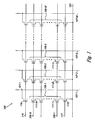
- Figure 1 is a schematic of a portion of a non-volatile memory array 100 in accordance with one or more embodiments of the present disclosure.
- the embodiment of Figure 1 illustrates a NAND architecture non-volatile memory.
- the memory array 100 includes access lines, e.g., word lines 105-1, . . ., 105-N and corresponding data lines, e.g., local bit lines 107-1, 107-2, 107-3, . . ., 107-M.
- the number of word lines 105-1,..., 105-N and the number of local bit lines 107-1, 107-2, 107-3, . . ., 107-M can be some power of two, e.g., 256 word lines by 4,096 bit lines.
- Memory array 100 includes NAND strings 109-1, 109-2, 109-3, . . ., 109-M.
- Each NAND string includes non-volatile memory cells 111-1, . . ., 111-N, each associated with a respective word line 105-1,..., 105-N.
- Each NAND string (and its constituent memory cells) is also associated with a local bit line 107-1, 107-2, 107-3,..., 107-M.
- each NAND string 109-1, 109-2, 109-3,..., 109-M are connected in series source to drain between a source select gate (SGS), e.g., a field-effect transistor (FET) 113, and a drain select gate (SGD), e.g., FET 119.
- SGS source select gate
- FET field-effect transistor
- SGD drain select gate
- Each source select gate 113 is configured to selectively couple a respective NAND string 109 to a common source 123 responsive to a signal on source select line 117
- each drain select gate 119 is configured to selectively couple a respective NAND string to a respective bit line 107 responsive to a signal on drain select line 115.
- Memory cells 111-1, 111-B, and 111-C are all coupled to word line 105-1, and are associated with bit lines 107-1, 107-2, and 107-3 respectively.
- a source of source select gate 113 is connected to a common source line 123.
- the drain of source select gate 113 is connected to the source of the memory cell 111-1 of the corresponding NAND string 109-1.
- the drain of drain select gate 119 is connected to the local bit line 107-1 for the corresponding NAND string 109-1 at drain contact 121-1.
- the source of drain select gate 119 is connected to the drain of the last memory cell 111-N, e.g., a floating-gate transistor, of the corresponding NAND string 109-1.
- construction of non-volatile memory cells, 111-1, . . ., 111-N includes a source, a drain, a floating gate or other charge storage node, and a control gate.
- Non-volatile memory cells, 111-1, . . ., 111-N have their control gates coupled to a word line, 105-1,..., 105-N respectively.
- a "column" of the non-volatile memory cells, 111-1, . . ., 111-N make up the NAND strings, e.g., 109-1, 109-2, 109-3, . .
- a "row" of the non-volatile memory cells are those memory cells commonly coupled to a given word line, e.g., 105-1,. . ., 105-N.
- the use of the terms “column” and “row” is not meant to imply a particular linear, e.g., vertical and/or horizontal, orientation of the non-volatile memory cells.
- a NOR array architecture would be similarly laid out, except that the string of memory cells would be coupled in parallel between the select gates.
- subsets of cells coupled to a selected word line can be programmed and/or sensed, e.g., read, together as a group.
- a programming operation e.g., a write operation, can include applying a number of program pulses, e.g., 16V-20V, to a selected word line in order to increase the threshold voltage (Vt) of selected cells coupled to that selected word line to a desired program voltage level corresponding to a desired programmed state.
- a sensing operation such as a read or program verify operation, can include sensing a voltage and/or current change of a bit line coupled to a selected cell in order to determine the state of the selected cell.
- the sensing operation can involve applying, e.g., biasing or driving, a voltage to a bit line, e.g., bit line 107-1, associated with a selected memory cell above a voltage applied to a source, e.g., source line 123, associated with the selected memory cell.
- a sensing operation could alternatively include precharging the bit line 107-1 followed with discharge when a selected cell begins to conduct, and sensing the discharge.
- Sensing the state of a selected cell can include applying one or more sensing voltages, e.g., read voltages "Vread,” to a selected word line while applying one or more voltages to the word lines coupled to the unselected cells of the string sufficient to place the unselected cells in a conducting state independent of the threshold voltage of the unselected cells, e.g., pass voltages "Vpass".
- the bit line corresponding to the selected cell being read and/or verified can be sensed to determine whether or not the selected cell conducts in response to the particular sensing voltage applied to the selected word line.
- the state of a selected cell can be determined by the word line voltage at which the bit line current reaches a particular reference current associated with a particular state.
- the unselected memory cells of the string are biased so as to be in a conducting state.
- the data stored in the selected cell can be based on the current and/or voltage sensed on the bit line corresponding to the string. For instance, data stored in the selected cell can be based on whether the bit line current changes by a particular amount or reaches a particular level in a given time period.
- the selected cell When the selected cell is in a conductive state, current flows between the source line contact at one end of the string and a bit line contact at the other end of the string. As such, the current associated with sensing the selected cell is carried through each of the other cells in the string, the diffused regions between cell stacks, and the select transistors.
- a program verify operation can include applying one or more program verify voltages to a selected word line, e.g., after a programming pulse, to determine whether a memory cell coupled to the selected word line has reached a desired programmed state.
- a cache element can store a programming status of the selected memory cell, e.g., whether the selected memory cell has reached the desired programmed state.
- the programming status of the selected memory cell can include one of programming complete and programming incomplete.
- the programming status of the selected memory cell Prior to performing the program verify operation, the programming status of the selected memory cell can be programming incomplete. If the program verify operation verifies that the selected memory cell has reached a desired programmed state, then the programming status, stored in the cache element, can be changed from programming complete to programming incomplete.
- Such a change in programming status can affect whether or not the selected memory cell will be program inhibited during subsequent programming pulse. For example, if the programming status stored in the cache element is programming incomplete, then the selected memory cell will not be program inhibited during a subsequent programming pulse applied to the selected word line. However, if the programming status stored in the cache element is programming complete, then the selected memory cell will be program inhibited during a subsequent programming pulse applied to the selected word line.
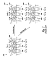
- Figure 2 illustrates capacitive coupling and programming kink during a programming operation.
- the first image 210 illustrates a first programming pulse, e.g., "Pulse N.”
- the second image 220 and the third image 230 each illustrate a different variation of a second programming pulse, e.g., "Pulse N+1.”
- a program verify operation can be performed between programming pulses to determine whether a selected memory cell has reached a desired programmed state, e.g., whether the selected memory cell will be program inhibited during a subsequent programming pulse.
- three memory cells 211-A, 211-B, and 211-C are having their charge storage nodes, e.g., floating gates "FG," programmed.
- Memory cells 211-A and 211-C are oppositely adjacent to the memory cell 211-B.
- the memory cells 211-A, 211-B, and 211-C are coupled to a word line 205.
- Each memory cell is associated with, e.g., coupled to, a bit line, e.g., bit lines 207-A, 207-B, and 207-C.
- bit lines 207-A and 207-C are oppositely adjacent to bit line 207-B.
- bit lines 207-A, 207-B, and 207-C illustrated in Figure 2 is intended to show an association between the memory cells 211-A, 211-B, and 211-C and the bit lines 207-A, 207-B, and 207-C respectively rather than a layout of the physical locations thereof.
- bit lines may be formed in a number of locations with respect to the memory cells with which they are associated.
- Memory cells 211-A, 211-B, and 211-C, coupled to word line 205 can be analogous to memory cells 111-1, 111-B, and 111-C, coupled to word line 105-1 in Figure 1 .
- bit lines 207-A, 207-B, and 207-C can be analogous to bit lines 107-1, 107-2, and 107-3 in Figure 1 .
- the images 210, 220, and 230 illustrate capacitive coupling between the floating gates of memory cell 211-B and the floating gates of adjacent memory cells 211-A and 211-C, represented by the capacitor symbol therebetween.
- the images 210, 220, and 230 also illustrate capacitive coupling between the floating gate of memory cell 211-B and channel regions underlying adjacent memory cells 211-A and 211-C, represented by the capacitor symbol therebetween. As memory devices are scaled to smaller sizes, capacitive coupling between adjacent components can increase because of the shorter distances between components.
- Applying a program inhibit voltage to a bit line, e.g., bit line 207-A can effectively turn off the drain select transistor, e.g., drain select transistor 119 illustrated in Figure 1 , and disconnect the NAND string, e.g., NAND string 109-1, from its associated bit line, e.g., bit line 107-1.
- This floats the channels associated with the memory cells of the NAND string so that a respective channel, e.g., the channel associated with memory cell 211-A, can be boosted to a voltage roughly proportional to a voltage applied to a respective word line, e.g., word line 205, associated with a respective memory cell.
- Boosting the channel as such can effectively reduce a potential difference between the channel and the charge storage unit, e.g., the floating gate, which can inhibit programming of the memory cell, e.g., discourage electron transfer between the channel and the charge storage unit.
- the charge storage unit e.g., the floating gate
- a program enable voltage e.g., 0 V
- a bit line e.g., bit line 207-B
- all three adjacent bit lines 207-A, 207-B, and 207-C have the same voltage applied thereto, e.g., a program enable voltage "Pgm.”
- a control gate of each memory cell 211-A, 211-B, and 211-C can have the same voltage applied thereto. Accordingly, there may be little adverse effect on memory cell 211-B because the adjacent bit lines 207-A and 207-C and channel regions are at essentially the same voltage as those associated with memory cell 211-B.
- the image 220 illustrates a programming pulse subsequent to Pulse N, e.g., Pulse N+1, in which one of the memory cells, e.g., memory cell 211-A, adjacent to memory cell 211-B is program inhibited.
- a programming pulse for memory cells associated with word line 205 is applied to word line 205, one or more memory cells that have completed programming can be inhibited from further programming by applying an inhibit voltage to bit lines associated with those cells.
- an inhibit voltage is applied to bit line 207-A to inhibit memory cell 211-A from further programming while memory cells 211-B and 211-C receive additional charge from the programming Pulse N+1 applied to word line 205.
- An inhibit voltage applied to a bit line may generally be larger than a program enable voltage applied to a bit line.
- Applying a program inhibit voltage to a bit line associated with a memory cell coupled to a selected word line, e.g., selected for programming, can effectively turn off a select transistor, e.g., applying a program inhibit voltage to bit line 107-1 can turn off drain select gate 119, as illustrated in Figure 1 .
- Turning off the select transistor can electrically disconnect a NAND string associated with the select transistor from the bit line, which can float a channel region underlying the memory cells of the NAND string.
- the program inhibit voltage applied to bit line 207-A can float the channel underlying memory cell 211-A, which can allow the channel to be boosted to the voltage applied to the word line 205 during the programming Pulse N+1.
- Such an increase in programming voltage step size can cause the memory cell being programmed to receive more charge than is intended as a result of the programming pulse.
- Such over-programming can contribute to sensing errors such as read errors and/or program verify errors, e.g., by shifting the Vt of the memory cell to a higher level, e.g., to a higher programmed state.
- the image 230 illustrates a programming pulse subsequent to Pulse N, e.g., Pulse N+1, in which both of the memory cells, e.g., memory cells 211-A and 211-C, adjacent to memory cell 211-B are being program inhibited.
- an inhibit voltage is applied to bit lines 207-A and 207-C to inhibit memory cells 211-A and 211-C from further programming while memory cell 211-B receives additional charge from the programming Pulse N+1 applied to word line 205.
- the program inhibit voltage applied to bit lines 207-A and 207-C can float the channels underlying memory cells 211-A and 211-C, which can allow the channels to be boosted to the voltage applied to the word line 205 during the programming Pulse N+1,
- the channel voltage associated with memory cells 211-A and 211-C can be greater than the channel voltage associated with memory cell 211-B during programming Pulse N+1.
- a double sided kink can affect the programming of the memory cell 211-B.
- the effective voltage applied to memory cell 211-B is the voltage applied to the word line 205 plus some kink due at least in part to capacitive coupling between the memory cell 211-B and the channels underlying memory cells 211-A and 211-C.
- Kink attributable to capacitive coupling with two adjacent channels is referred to as double sided kink.
- double sided kink can be approximately 300mV, which could increase a programming voltage step size from 500mV to 800mV.
- single sided kink such an increase in programming voltage step size can contribute to operational errors for the memory cell being programmed.
- double sided kink can cause a programming voltage step increase larger than single sided kink, which can increase the likelihood of operational error.
- Figure 3 is a prior art graph of program step voltage versus pulse number for a programming operation according to some previous approaches.
- the graph of Figure 3 illustrates a series of programming pulses, e.g., pulses 1-10.
- each pulse has a 500mV step size. That is, each successive programming pulse is 500mV larger than the previous pulse. For example, if pulse 1 is applied at 10V, then pulse two is applied at 10.5V, however embodiments are not limited to these example voltages.
- a particular memory cell undergoing programming e.g., memory cell 211-B in image 220 of Figure 2 , experiences a single sided kink, which can effectively increase the programming pulse step size by about 150mV from 500mV to about 650mV.
- a particular memory cell undergoing programming e.g., memory cell 211-B in image 230 of Figure 2
- experiences a double sided kink which can effectively increase the programming pulse step size by about 300mV from 500mV to about 800mV.
- the specific voltages given are examples, and different memory devices may operate with and/or experience different voltage levels.
- one or more embodiments of the present disclosure can help reduce the effects of programming kink as described herein.
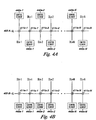
- Figures 4A-4B are schematics of a portion of a memory array with a number of control elements according to one or more embodiments of the present disclosure.
- Figures 4A-4B include a number of memory cells 411 e-1, 411o-1, 411e-2, 411o-2, . . ., 411e-N, 411o-N coupled to a word line, e.g., word line 405-A in Figure 4A and word line 405-B in Figure 4B .
- the bit lines are coupled to control elements 440e-1, 440o-1, 440e-2, 440o-2, . . ., 440e-N, 440o-N.
- Memory cells associated with "even numbered” bit lines are denoted as squares while memory cells associated with "odd numbered” bit lines are denoted as circles, although there is not necessarily a physical difference between the even and odd numbered memory cells or bit lines themselves. In other words, "even” and “odd” are only used herein as respective references.
- the control elements 440e-1, 440o-1, 440e-2, 440o-2, . . ., 440e-N, 440o-N can include and/or be coupled to control circuitry for operating the bit lines DLe-1, DLo-1, DLe-2, DLo-2, . . ., DLe-N, DLo-N.
- Such control circuitry can include programming circuitry, sensing circuitry, and/or one or more cache elements to be used in association with the respective bit lines.
- the control elements can include a dynamic data cache (DDC).
- 440e-N, 440o-N can include and/or be coupled to one or more features illustrated in Figure 8 , e.g., row decode circuitry 844, column decode circuitry 846, read/latch circuitry 850, write circuitry 855, address circuitry 840, I/O circuitry 860, and control circuitry 870.
- Figure 4A illustrates that control elements associated with bit lines can be coupled on opposite sides of a memory array for even and odd bit lines.
- Figure 4A includes control elements 440e-1, 440e-2,. . ., 440e-N coupled to one end, e.g., the "top,” of bit lines DLe-1, DLe-2,. . ., DLe-N with respect to the array of memory cells including memory cells 411e-1, 411o-1, 411e-2, 411 o-2, . . ., 411e-N, 411o-N.
- ., 440o-N are coupled to the other end, e.g., the "bottom," of bit lines DLo-1, DLo-2, . .., DLo-N respectively.
- Embodiments are not limited to even numbered control elements being on “top” and odd numbered control elements being on “bottom.”
- Figure 4B includes the control elements 440e-1, 440o-1, 440e-2, 440o-2, . . ., 440e-N, 440o-N coupled to a common side of the bit lines DLe-1, DLo-1, DLe-2, DLo-2, . . ., DLe-N, DLo-N with respect to the array of memory cells including memory cells 411e-1, 411o-1, 411e-2, 411o-2, . . ., 411e-N, 411o-N.
- the control elements are illustrated as being coupled to the "bottom" of the bit lines with respect to the memory array, embodiments are not so limited.
- control elements could likewise all be coupled to the "top” of the bit lines with respect to the memory array. Furthermore, with respect to Figures 4A-4B , there is no significant difference between the "top” and “bottom” of the bit lines with respect to the memory array. Rather, the terms “top” and “bottom” are used to provide points of reference.
- control elements 440e-1, 440o-1, 440e-2, 440o-2, . . ., 440e-N, 440o-N can be configured to perform a kink check before a programming pulse.
- a kink check can be an operation that includes determining whether one or more memory cells adjacent to a particular memory cell, and coupled to a common word line, will be program inhibited during a subsequent programming pulse, e.g., whether the one or more adjacent memory cells have completed programming.
- a kink check can be performed for memory cell 411-o1 by first determining whether memory cells 411-e1 and 411-e2 will be program inhibited during a subsequent programming pulse.
- such programming status information can be stored in a cache element associated with a particular memory cell.
- a particular memory cell e.g., memory cell 411-e1 coupled to a bit line, e.g., bit line DLe-1, can be program inhibited for a programming pulse when the particular memory cell has completed programming to help prevent the programming pulse applied to a word line, e.g., word line 405-A, coupled to the particular memory cell from putting additional charge on a floating gate of the particular memory cell.
- a control element e.g., control element 440e-1
- can program inhibit a memory cell e.g., memory cell 411e-1
- a program inhibit voltage to a bit line, e.g., bit line DLe-1, associated with the memory cell.
- a NAND string, and the memory cells associated therewith can be disconnected from their associated bit line by turning off a select gate corresponding to the bit line.
- NAND string 109-1 can be disconnected from bit line 107-1 by turning off drain select gate 119.
- programming status information for a particular memory cell can be stored in a particular cache element associated with the particular memory cell. Because information is not needed directly from the particular memory cell during the kink checking operation, the string and associated memory cells can be disconnected from the bit line so as not to interfere with a sensing operation associated with the kink checking operation. As such, a bit line voltage sensed during a kink checking operation reacts to the voltages applied to the bit lines as part of the kink checking operation, and not to a programmed state of one or more memory cells.
- a kink check can be performed for all memory cells associated with a word line selected for programming.
- Such a kink check can include performing a first kink check and a second kink check before a programming pulse.
- the first kink check can include kink checking the odd numbered bit lines DLo-1, DLo-2, . . ., DLo-N by floating odd numbered bit lines DLo-1, DLo-2, . . ., DLo-N and selectively applying one of two voltages to each of the even numbered bit lines DLe-1, DLe-2,. . ., DLe-N according to, e.g., dependent upon, a programming status of a memory cell 411 e coupled to the respective even numbered bit lines DLe and to the access line 405.
- a first voltage can be applied, e.g., zero volts
- a second voltage can be applied, e.g., 1V.
- a programming status for a particular memory cell can be stored in a cache element associated with the particular memory cell and updated according to a result of one or more program verify operations performed on the selected memory cell, e.g., in association with one or more programming pulses applied to a word line associated with the particular memory cell.
- Embodiments are not limited to applying 0V as the first voltage or 1V as the second voltage, as these values are given to illustrate an example. While such voltages are applied to the even numbered bit lines, each of the odd numbered bit lines can be sensed to determine an effect thereon due at least in part to the voltage(s) applied to the respective adjacent even numbered bit lines. That is, while a particular odd numbered bit line, e.g., bit line DLo-1 is floated, the first and/or the second voltages applied to the adjacent even numbered data lines, e.g., data lines DLe-1 and DLe-2, can cause a voltage increase on the particular odd numbered bit line through capacitive coupling therewith.
- a particular odd numbered bit line e.g., bit line DLo-1
- the first and/or the second voltages applied to the adjacent even numbered data lines e.g., data lines DLe-1 and DLe-2
- bit line DLe-1 and DLe-2 adjacent to bit line DLo-1, e.g., when neither adjacent memory cell has completed programming
- capacitive coupling between bit line DLo-1 and bit lines DLe-1 and DLe-2 can yield a 0V increase, e.g., zero kink.
- bit line DLo-1 If 0V is applied to one of bit lines DLe-1 and DLe-2 adjacent to bit line DLo-1 and 1V is applied to the other of bit lines DLe-1 and DLe-2, e.g., when one adjacent memory cell has completed programming, then the voltage on bit line DLo-1 can increase by approximately 0.5V due at least in part to capacitive coupling with bit lines DLe-1 and DLe-2. If 1V is applied to both bit lines DLe-1 and DLe-2, e.g., when both adjacent memory cells have completed programming, then the voltage on bit line DLo-1 may increase by approximately 1V due at least in part to capacitive coupling with bit lines DLe-1 and DLe-2. Thus, by sensing bit line DLo-1, a determination can be made as to whether a double sided kink, a single sided kink, or no kink will occur during a subsequent programming pulse applied to the access line 405.
- Some previous approaches to addressing programming kink may have relied on sensing each adjacent bit line and making adjustments according to sensing the adjacent bit lines.
- Such previous approaches may include a tangible physical connection, e.g., drawn lines, between control elements, which can be impractical for instances where control elements are on opposite sides of the memory array, e.g., as illustrated in FIG. 4A .
- US2005/0057967 discloses a programming circuit in which an offset to a perturbation is added to an adjacent memory storage unit still under programming.
- the offset is added as voltage offset to a bit line of a storage unit under programming.
- the voltage offset is a predetermined function of whether none or one or both of its neighbors are in a mode that creates perturbation, such as in a program inhibit mode.
- control elements are on a same side of the memory array, e.g., as illustrated in FIG. 4B , such implementations can be difficult to implement and costly in terms of manufacturability and materials.
- one or more embodiments of the present disclosure use capacitive coupling between two or more adjacent bit lines and/or strings and/or memory cells to provide information such that sensing a particular bit line provides sufficient information about adjacent bit lines to make a determination as to whether double sided kink, single sided kink, or no kink will be present on a subsequent programming pulse applied to a memory cell coupled to the particular bit line.
- the second kink check can include kink checking the even numbered bit lines DLe-1, DLe-2, DLe-N with an operation similar to the first kink check, but having the even and odd numbered bit lines operated oppositely as in the first kink check. That is, the even numbered bit lines DLe-1, DLe-2, DLe-N can be floated while one of two voltages is selectively applied to each of the odd numbered bit lines DLo-1, DLo-2, ... , DLo-N according to a programming status of a memory cell 411o coupled to the respective odd numbered bit line and to the access line 405.
- each of the even numbered bit lines can be sensed to determine an effect thereon due at least in part to the voltage(s) applied to the respective adjacent odd numbered bit lines.
- either the odd or the even numbered bit lines can be checked first. That is, embodiments are not limited to checking the odd numbered bit lines first as described above.
- a kink correction can be applied to the particular bit line associated with that particular memory cell during a subsequent programming pulse.
- a kink correction voltage can be applied to the particular bit line, e.g., in addition to the program enable voltage applied to the particular bit line, according to the number of memory cells adjacent to the particular memory cell that will be program inhibited, e.g., according to the number of adjacent memory cells that have completed programming.
- the magnitude of the kink correction voltage can be proportional to the voltage sensed on the bit line during the kink check.
- 0V can be applied as a kink correction voltage
- 150mV can be applied as a kink correction
- 300mV can be applied as a kink correction.
- Embodiments are not limited to these example voltages.
- Applying a kink correction to the bit line can include applying a voltage greater than a voltage that would otherwise be applied to the bit line during programming of a memory cell coupled to the bit line, but less than a program inhibit voltage. For example, if 0V would otherwise be applied to a particular bit line during programming and Vcc, e.g., 2V, would be applied to program inhibit a memory cell coupled to the bit line, a single sided kink correction can include applying 300mV and a double sided kink correction can include applying 600mV to the particular bit line. Embodiments are not limited to the specific voltages used in these examples.
- Kink correction voltages can be sufficient to reduce the kink effects of capacitive coupling between a particular memory cell and one or more adjacent memory cells such that a programming pulse has its intended effect on the particular memory cell, e.g., a 15.0V programming pulse applied to the word line is received by the memory cell as 15.0V rather than as 15.3V due at least in part to capacitive coupling with one or more adjacent memory cells.
- kink correction voltages can reduce the effect of a programming pulse applied to the word line for a memory cell associated with the bit line and the word line, e.g., an increased voltage on DLo-1 can decrease the effect of a programming pulse on word line 405-A for memory cell 411o-1 by reducing the potential difference between the word line, e.g., from a programming pulse applied thereto, and the channel underlying the floating gate.
- increasing the bit line voltage for a particular memory cell can cause a corresponding increase in the channel voltage for the memory cell.
- Kink correction voltages are not of sufficient magnitude to place the bit line, and memory cells coupled thereto, into a program inhibit mode such that a programming pulse applied to the memory cell does not alter the state of the memory cell, e.g., an amount of charge on a floating gate of the memory cell.
- a number of operations can be performed on a memory device in the order of: programming pulse, program verify operation, and kink check, possibly followed by a subsequent programming pulse with kink correction.
- Figure 5A is a timing diagram associated with a first kink checking operation according to one or more embodiments of the present disclosure.
- Image 550 illustrates three example bit line voltages 0V, 0.5V and 1 V associated with an example embodiment for a kink check as described herein.
- the particular voltages 0V, 0.5V, and 1V are examples and one or more embodiments described herein can use different voltages.
- a kink check can include sensing a particular bit line to determine an effect thereon due at least in part to capacitive coupling between the particular bit line and adjacent bit lines that have one of two voltages, e.g., 0V or 1V, applied according to a programming status of the memory cells associated therewith.
- the particular bit line voltage due at least in part to capacitive coupling for these example voltages can therefore be approximately 0V, e.g., for no kink, 0.5V, e.g., for single sided kink, or 1V, e.g., for double sided kink.
- a first sense voltage 551 e.g., 0.25V
- a second sense voltage 552 e.g., 0.75V
- Embodiments are not limited to these example voltages or to this particular sensing scheme.
- other sensing schemes can be used such as may employ a voltage ramp for sensing, as will be appreciated by one of ordinary skill in the art.
- the timing diagram associated with Figure 5A includes a signal tdc 553-A, which corresponds to the temporary data cache (tdc) node 553-A illustrated in the schematic of Figure 5C , e.g., the line between switch 559-2 and switch 559-3.
- the timing diagram also includes a signal DLCLAMP 554-A, which corresponds to the DLCLAMP 554-C line illustrated in the schematic of Figure 5C .
- An appropriate DLCLAMP signal 554-C can couple the bit line 507 to the tdc node 553-C by operation of the switch 559-2. While the term "switch" is used herein, the switching device may be a transistor (as shown) or another type of switching device.
- the tdc signal 553-A increases to Vcc.
- such an increase on tdc node 553-C can occur when precharging circuitry, e.g., Vcc, 556-1 is coupled to tdc node 553-C via operation of switch 559-1.
- Connecting Vcc 556-1 to tdc node 553-C can charge the capacitance, e.g., a discrete capacitor and/or parasitic capacitance, 557-1 to Vcc when switches 559-2 and 559-3 are off and switch 559-4 is on.
- a sense voltage 551 can be applied to DLCLAMP line 554-C, as illustrated by DLCLAMP signal 554-A.
- the sense voltage applied to DLCLAMP line 554-C can be a desired sense voltage plus a threshold voltage associated with the switch 559-1, e.g., a voltage sufficient to fully turn on the transistor, although embodiments are not so limited.
- the bit line 507 can have one of three voltages thereon, e.g., 0V, 0.5V, or 1V.
- switch 559-2 will turn on when the bit line 507 is lower than the sense voltage, e.g., 0V, but not when the bit line 507 is higher than the sense voltage, e.g., 0.5V or IV.
- the tdc signal 553-A drops to the voltage on the bit line, e.g., as represented by the dotted line, when the voltage on the bit line is 0.
- switch 559-2 turns on allowing the capacitance 557-1, which was previously charged to Vcc, to drain out through the data line so that tdc node 553-C drains toward the bit line voltage, e.g., 0V.
- Switch 559-3 can be turned on to latch 558 this information, e.g., to record the fact that the bit line 507 is at 0V.
- the switch 559-2 will not turn on, which leaves the voltage on tdc node 553-C at Vcc, e.g., the voltage to which capacitance 557-1 is charged, as illustrated by the solid line on tdc signal 553-A remaining at Vcc after DLCLAMP 554-A rises to the sensing voltage + Vtn.
- the switch 559-3 is turned on, the latch 558 can record the fact that the bit line 507 is at a voltage greater than sense voltage 551. Subsequently, sense voltage 552 can be applied to determine whether the bit line 507 is at 0.5V or 1V.
- the latch 558 can have a particular trip point, e.g., approximately 1V, although embodiments are not so limited. Vcc can be some value greater than the trip point of the latch 558, e.g., 2V.
- Vcc can be some value greater than the trip point of the latch 558, e.g., 2V.
- the latch will trip when tdc node 553-C remains at Vcc, e.g., when the bit line is at 0.5V or 1V.
- the latch will not trip when the voltage on tdc node 553-C drains toward the bit line voltage of 0V.
- Figure 5B is a timing diagram associated with a second kink checking operation according to one or more embodiments of the present disclosure.
- Figure 5B relates to the application of sensing voltage 552 to DLCLAMP line 554-C to distinguish between 0.5V and 1V on the bit line 507.
- Figure 5B includes a signal 553-B representing the voltage on tdc node 553-C, a DCLAMP signal 554-B, and a boost voltage signal 555, e.g., Vcc/2.
- the capacitance 557-1 associated with tdc node 553-C can be charged to Vcc with respect to ground as described in connection with Figure 5A , and as illustrated by the tdc signal 553-B. Subsequently a boost voltage signal 555 can be used to boost the voltage of tdc signal 553-B with respect to ground.
- the boost voltage is Vcc/2, however embodiments are not limited to this specific example boost voltage.
- the boost voltage can be applied to tdc node 553-C by charging the capacitance 557-2 to Vcc/2.
- Capacitance 557-2 can be coupled to boosting circuitry, e.g., Vcc/2, 556-2 across the capacitance 557-2 to ground by turning on switch 559-5. Subsequently, switch 559-4 can be turned off while switch 559-6 is turned on such that capacitances 557-1 and 557-2 are coupled in series to tdc node 553-C, yielding a potential of Vcc + Vcc/2 above ground.
- boosting circuitry e.g., Vcc/2, 556-2 across the capacitance 557-2 to ground by turning on switch 559-5. Subsequently, switch 559-4 can be turned off while switch 559-6 is turned on such that capacitances 557-1 and 557-2 are coupled in series to tdc node 553-C, yielding a potential of Vcc + Vcc/2 above ground.
- the sense voltage 552 can be applied to DLCLAMP line 554-B.
- the sense voltage 552 can be applied as the sense voltage plus a threshold voltage of the transistor 559-2 associated with DLCLAMP line 554-C, although embodiments are not so limited. If the bit line 507 is at 1V, the switch 559-2 will not turn on by application of the sense voltage 552, e.g., 0.75V, to DLCLAMP line 554-C. Thus, tdc node 553-C remains at Vcc + Vcc/2.
- the latch 558 when the latch 558 is coupled to the tdc node 553-C by turning on switch 559-3, it will read Vcc + Vcc/2 as indicated by the solid line on tdc 553-B, e.g., 3V, which can be sufficient to trip the latch, indicating that the bit line 507 is above the sense voltage, e.g., 1V. Conversely, if the bit line 507 is at 0.5V, application of the sensing voltage 552 to DLCLAMP line 554-C will turn on the switch 559-2 to couple the bit line 507 to the tdc node 553-C. The tdc node 553-C can begin to drain to the bit line 507 voltage as indicated by the dotted line on tdc signal 553-B.
- the latch 558 can have a particular trip point, e.g., approximately 1V. In some instances, 0.5V on the bit line 507 may be sufficiently close to the latch trip point, particularly when process corners, such as operating temperature, which can affect operating voltages of the device are considered, to cause erroneous operation of the latch 558. Accordingly, after draining tdc as described above, the boost voltage can be removed by switching, as indicated by boost signal 555 going low after application of the sensing voltage 552 to DLCLAMP line 554-C. Removing the boost voltage can shift the voltage on tdc node 553-C lower than the bit line 507 voltage to help prevent erroneous operation of the latch 558.
- the tdc node 553-C voltage e.g., Vcc + Vcc/2
- the bit line 507 voltage e.g., 0.5V
- switch 559-6 can be turned off and switch 559-4 can be turned on to uncouple capacitance 557-2 between the tdc node 553-C and ground.
- Such operation will effectively reduce the tdc node 553-C voltage by the portion of the tdc node 553-C voltage stored on the capacitance 557-2.
- the tdc voltage will drop from the bit line voltage, e.g., 0.5V to some lesser voltage.
- Such an operation can reduce the voltage sensed by the latch 558 to help prevent erroneous operation thereof.
- Figure 5C is a schematic of sensing circuitry according to one or more embodiments of the present disclosure.
- the sensing circuitry associated with Figure 5C can be included with and/or coupled to one or more control elements, e.g., control elements 440e-1, 440o-1, 440e-2, 440o-2, . . ., 440e-N 440o-N illustrated in Figures 4A and 4B .
- Figure 5C is one example of a sensing circuit that can be used with the present disclosure.
- Switches that can be used to alter one or more electrical paths of the sensing circuit, e.g., between configurations applicable for sensing operations using the first sense voltage 551 or the second sense voltage 552, e.g., switches 559-4, 559-5, and 559-6 can be reconfigured to provide a number of alternate implementations.
- embodiments are not limited to the use of metal oxide semiconductor field effect transistors (MOSFET) as switching elements for the sensing circuitry illustrated in Figure 5C .
- MOSFET metal oxide semiconductor field effect transistors
- the sensing circuit and operation can effectively determine the voltage on a selected bit line 507 due at least in part to capacitive coupling with one or more adjacent bit lines in order to perform a kink check, as described herein.
- Figure 6 is a schematic of programming circuitry according to one or more embodiments of the present disclosure.
- the programming circuitry associated with Figure 6 can be included with and/or coupled to one or more control elements, e.g., control elements 440e-1, 440o-1, 440e-2, 440o-2, . . ., 440e-N, 440o-N illustrated in Figures 4A and 4B .
- programming circuitry can be selectively coupled to a data line "DL" 607, e.g., a bit line, responsive to DLCLAMP line 654 and include a supply voltage 656 and a program/inhibit latch 658.
- Program/inhibit latch 658 can be analogous to program inhibit latch 558 illustrated in Figure 5C .
- DLCLAMP line 654 can be included as a component of the programming circuitry or be a separate element therefrom.
- DLCLAMP line 654 can be analogous to DLCLAMP line 554-C illustrated in Figure 5C .
- a same DLCLAMP signal can be used to selectively couple a bit line to programming circuitry and sensing circuitry.
- additional switching devices can be included to selectively couple the bit line to sensing or programming circuitry.
- DLCLAMP line 654 can be different from DLCLAMP line 554-C.
- sensing circuitry e.g., the sensing circuitry illustrated in Figure 5C
- programming circuitry e.g., programming circuitry illustrated in Figures 6 and 7
- a common control element e.g., a control element 440 illustrated in Figure 4A and 4B .
- the programming circuitry can include a number of storage elements, e.g., DDCs 660-1, 660-2, 660-3, 660-4, 660-5, and 660-6.
- the DDCs can be utilized to apply a particular kink correction voltage to the bit line 607.
- DDC 660-1 can be used to apply 0V to the bit line 607;
- DDC 660-2 can be used to apply a single sided kink correction, e.g., dekink, voltage, e.g., 1/2 dekink, to the bit line 607;
- DDC 660-3 can be used to apply a double sided dekink, e.g., dekink, voltage to the bit line 607;
- DDC 660-4 can be used to apply a selective slow programming convergence (SSPC) voltage to the bit line 607;
- DDC 660-5 can be used to apply an SSPC + 1 ⁇ 2 dekink voltage to the bit line 607; and
- DDC 660-6 can be used to apply an SSPC + dekink voltage to the bit line 607.
- the power supply e.g., Vcc 656, may be referred to as a seventh storage element for applying Vcc to the bit line 607.
- a 1 ⁇ 2 dekink voltage can be a voltage applied to the bit line 607 to correct a single side programming kink, e.g., an instance in which one adjacent bit line is program inhibited during a programming operation.
- a (full) dekink voltage can be a voltage applied to the bit line 607 to correct a double sided programming kink, e.g., an instance in which two adjacent bit lines are program inhibited during a programming operation.
- Selective slow programming convergence is a technique sometimes used with NAND memory to generate a very narrow threshold voltage (Vth) distribution without reducing programming throughput.
- Applying an SSPC voltage to a bit line associated with a memory cell selected to receive a programming pulse can reduce the effect of the programming pulse applied to a word line associated with the selected memory cell.
- the SSPC voltage can reduce the channel associated with the selected memory cell to an intermediate voltage between a program inhibit voltage and what would otherwise be a programming voltage applied to the bit line.
- the SSPC voltage "slows" the programming of the selected memory cell.
- One or more kink correction programming operations of the present disclosure can be used in conjunction with SSPC programming operations to both narrow the Vth of a selected memory cell and to reduce the effect of programming kink associated with some previous approaches. For example, if an SSPC voltage is 100mV and a 1 ⁇ 2 dekink voltage is 150mV, then an SSPC + 1 ⁇ 2 dekink voltage can be 250mV. Embodiments are not limited to these example voltages.
- the storage elements 660-1, 660-2, 660-3, 660-4, 660-5, and 660-6, e.g., DDCs, illustrated in Figure 6 may be referred to as decoded storage elements. That is, each storage element can be associated with one particular operating voltage.
- one or more embodiments of the present disclosure can utilize encoded storage elements in lieu of decoded storage elements.
- Figure 6 includes seven decoded storage elements, e.g., DDCs 660-1, 660-2, 660-3, 660-4, 660-5, and 660-6 and Vcc 656.
- Figure 6 could alternatively include three encoded storage elements to replace the seven decoded storage elements. Each of the three encoded storage elements can be analogized to one bit of a three digit binary number. The combination of the three encoded storage elements can provide up to nine different combinations, which is sufficient to provide for selection of one of the seven operating voltages associated with Figure 6 as illustrated.
- Figure 7 is a schematic of programming circuitry according to one or more embodiments of the present disclosure.
- the programming circuitry associated with Figure 7 can be included with and/or coupled to one or more control elements, e.g., control elements 440e-1, 440o-1, 440e-2, 440o-2, . . ., 440e-N, 440o-N illustrated in Figures 4A and 4B .
- programming circuitry can be selectively coupled to a bit line 707 responsive to DLCLAMP line 754 and include a supply voltage 756 and a program/inhibit latch 758.
- DLCLAMP line 754 can be analogous to DLCLAMP line 654 illustrated in Figure 6 .
- Program/inhibit latch 758 can be analogous to program/inhibit latch 658 illustrated in Figure 6 .
- the programming circuitry can include a number of storage elements, e.g., DDCs 760-1, 760-2, 760-3, and 760-4.
- the DDCs can be utilized to apply a particular voltage to the data line "DL" 707, e.g., bit line.
- DDC 760-1 can be used to apply 0V to the bit line 707; DDC 760-2 can be used to apply a kink correction, e.g., dekink, voltage; DDC 760-3 can be used to apply an SSPC voltage to the bit line 707; and DDC 760-4 can be used to apply an SSPC + dekink voltage to the bit line 707.
- the power supply e.g., Vcc 756, may be referred to as a fifth storage element for applying Vcc to the bit line 707.
- both single and double sided programming kinks can be corrected with application of one dekink voltage. That is, if any programming kink is detected, a singular dekink voltage can be applied during a programming pulse. Such embodiments can reduce the amount of space consumed on a memory device for sensing circuitry to check for a programming kink and/or programming circuitry to correct for a programming kink.
- the sensing circuitry can be reduced by treating both single and double sided programming kink similarly.
- one or more embodiments of the present disclosure that treat single and double sided programming kinks equally would only distinguish between no kink and some kink, e.g., 0V and (0.5V or 1V), according to the example of image 550 in Figure 5A .
- the sensing circuitry used to distinguish between 0V and (0.5V or 1V) might not be included, or the sensing circuitry used to distinguish between 0.5V and 1V might not be included with such embodiments.
- these embodiments can also reduce a sensing time associated with checking programming kinks.
- FIG 8 is a functional block diagram of an electronic memory system 800 having at least one memory device 820 operated in accordance with one or more embodiments of the present disclosure.
- Memory system 800 includes a processor 810 coupled to a non-volatile memory device 820 that includes a memory array 830 of non-volatile cells, e.g., memory array 100 of non-volatile cells 111-1, . . ., 111-N shown in Figure 1 .
- the memory system 800 can include separate integrated circuits or both the processor 810 and the memory device 820 can be on the same integrated circuit.
- the processor 810 can be a microprocessor or some other type of controlling circuitry such as an application-specific integrated circuit (ASIC).
- ASIC application-specific integrated circuit
- the memory device 820 includes an array of non-volatile memory cells 830, which can be floating gate flash memory cells with a NAND architecture, as previously described herein.
- the embodiment of Figure 8 includes address circuitry 840 to latch address signals provided over I/O connections 862 through I/O circuitry 860. Address signals are received and decoded by a row decoder 844 and a column decoder 846 to access the memory array 830.
- address circuitry 840 to latch address signals provided over I/O connections 862 through I/O circuitry 860. Address signals are received and decoded by a row decoder 844 and a column decoder 846 to access the memory array 830.
- the number of address input connections depends on the density and architecture of the memory array 830 and that the number of addresses increases with both increased numbers of memory cells and increased numbers of memory blocks and arrays.
- the memory device 820 senses data in the memory array 830 by sensing voltage and/or current changes in the memory array columns using sense/buffer circuitry that in this embodiment can be read/latch circuitry 850.
- the read/latch circuitry 850 can read and latch a page, e.g., a row, of data from the memory array 830.
- I/O circuitry 860 is included for bi-directional data communication over the I/O connections 862 with the processor 810.
- Write circuitry 855 is included to write data to the memory array 830.
- Control circuitry 870 decodes signals provided by control connections 872 from the processor 810. These signals can include chip signals, write enable signals, and address latch signals that are used to control the operations on the memory array 830, including data sensing, data write, and data erase operations, as described herein. In one or more embodiments, the control circuitry 870 is responsible for executing instructions from the processor 810 to perform the operations according to embodiments of the present disclosure.
- the control circuitry 870 can be a state machine, a sequencer, or some other type of controller. It will be appreciated by those skilled in the art that additional circuitry and control signals can be provided, and that the memory device detail of Figure 8 has been reduced to facilitate ease of illustration.
- FIG. 9 is a functional block diagram of a memory module 900 having at least one memory device operated in accordance with one or more embodiments of the present disclosure.
- Memory module 900 is illustrated as a memory card, although the concepts discussed with reference to memory module 900 are applicable to other types of removable or portable memory (e.g., USB flash drives and/or solid-state drives) and are intended to be within the scope of "memory module" as used herein.
- memory module e.g., USB flash drives and/or solid-state drives
- memory module 900 will include a housing 905 (as depicted) to enclose one or more memory devices 910, though such a housing is not essential to all devices or device applications.
- At least one memory device 910 includes an array of non-volatile multilevel memory cells, e.g., array 100 of non-volatile memory cells 111-1, . . ., 111-N shown in Figure 1 .
- the housing 905 includes one or more contacts 915 for communication with a host device. Examples of host devices include digital cameras, digital recording and playback devices, PDAs, personal computers, memory card readers, interface hubs and the like.
- the contacts 915 are in the form of a standardized interface.
- the contacts 915 might be in the form of a USB Type-A male connector.
- the contacts 915 are in the form of a semi-proprietary interface, such as might be found on CompactFlashTM memory cards licensed by SanDisk Corporation, Memory StickTM memory cards licensed by Sony Corporation, SD Secure DigitalTM memory cards licensed by Toshiba Corporation and the like. In general, however, contacts 915 provide an interface for passing control, address and/or data signals between the memory module 900 and a host having compatible receptors for the contacts 915.
- the memory module 900 may optionally include additional circuitry 920, which may be one or more integrated circuits and/or discrete components.
- the additional circuitry 920 may include control circuitry, such as a memory controller, for controlling access across multiple memory devices 910 and/or for providing a translation layer between an external host and a memory device 910.
- control circuitry such as a memory controller
- a memory controller could selectively couple an I/O connection (not shown in Figure 9 ) of a memory device 910 to receive the appropriate signal at the appropriate I/O connection at the appropriate time or to provide the appropriate signal at the appropriate contact 915 at the appropriate time.
- the communication protocol between a host and the memory module 900 may be different than what is used for access of a memory device 910.
- a memory controller could then translate the command sequences received from a host into the appropriate command sequences to achieve the desired access to the memory device 910. Such translation may further include changes in signal voltage levels in addition to command sequences.
- the additional circuitry 920 may further include functionality unrelated to control of a memory device 910 such as logic functions as might be performed by an ASIC. Also, the additional circuitry 920 may include circuitry to restrict read or write access to the memory module 900, such as password protection, biometrics or the like. The additional circuitry 920 may include circuitry to indicate a status of the memory module 900. For example, the additional circuitry 920 may include functionality to determine whether power is being supplied to the memory module 900 and whether the memory module 900 is currently being accessed, and to display an indication of its status, such as a solid light while powered and a flashing light while being accessed. The additional circuitry 920 may further include passive devices, such as decoupling capacitors to help regulate power requirements within the memory module 900.
- One method embodiment includes selectively applying one of a plurality of, e.g., two, voltages to a first data line according to a programming status of a first memory cell (where the first memory cell is coupled to the first data line and to a selected access line).
- An effect on a second data line is determined due at least in part to the voltage applied to the first data line and capacitive coupling between at least the first data line and the second data line (where a second memory cell is coupled to the second data line, and the second memory cell is adjacent to the first memory cell and is coupled to the selected access line).
- a kink correction is applied to the second data line, responsive to the determined effect, during a subsequent programming pulse applied to the second memory cell.
- B can include (only A), (only B), or (both A and B).
- a or B can mean “A and/or B” or “one or more of A and B.”
Landscapes
- Read Only Memory (AREA)
- Semiconductor Memories (AREA)
- For Increasing The Reliability Of Semiconductor Memories (AREA)
- Non-Volatile Memory (AREA)
Claims (15)
- Procédé d'exploitation d'un dispositif de mémoire (820, 910), comprenant les étapes ci-dessous consistant à :appliquer de manière sélective l'une d'une pluralité de tensions à une première ligne de données (107-1, DLe-1) selon un état de programmation d'une première cellule de mémoire (111-1, 411e-1), dans lequel la première cellule de mémoire (111-1, 411e-1) est couplée à la première ligne de données (107-1, DLe-1) et à une ligne d'accès sélectionnée (105-1, 405-A, 405-B) ;déterminer un effet sur une deuxième ligne de données (107-2, DLo-1), occasionné au moins en partie par la tension appliquée à la première ligne de données (107-1, DLe-1) et un couplage capacitif entre au moins la première ligne de données (107-1, DLe-1) et la deuxième ligne de données (107-2, DLo-1), dans lequel la deuxième ligne de données (107-2, DLo-1) est couplée à une deuxième cellule de mémoire (111-B, 411o-1), la deuxième cellule de mémoire (111-B, 411o-1) est adjacente à la première cellule de mémoire (111-1, 411e-1), et la deuxième cellule de mémoire (111-B, 411o-1) est couplée à la ligne d'accès sélectionnée (105-1, 405-A, 405-B); etappliquer une correction d'effet de boucle à la deuxième ligne de données (107-2, DLo-1), en réponse à l'effet déterminé, au cours d'une impulsion de programmation subséquente appliquée à la deuxième cellule de mémoire (111-B, 411o-1).
- Procédé selon la revendication 1, dans lequel la détermination de l'effet sur la deuxième ligne de données (107-2, DLo-1) consiste à déterminer l'effet tandis que l'une de la pluralité de tensions est appliquée à la première ligne de données (107-1, DLe-1).
- Procédé selon la revendication 1 ou 2, dans lequel l'application sélective de l'une de la pluralité de tensions inclut les étapes ci-dessous consistant à :appliquer une première tension de contrôle d'effet de boucle lorsque l'état de programmation de la première cellule de mémoire (111-1, 411e-1) correspond à une programmation inachevée ; etappliquer une seconde tension de contrôle d'effet de boucle lorsque l'état de programmation de la première cellule de mémoire (111-1, 411e-1) correspond à une programmation achevée.
- Procédé selon la revendication 1 ou 2, dans lequel l'application d'une correction d'effet de boucle à la deuxième ligne de données (107-2, DLo-1) consiste à appliquer une tension de correction d'effet de boucle à la deuxième ligne de données (107-2, DLo-1).
- Procédé selon la revendication 4, dans lequel l'application de la tension de correction d'effet de boucle consiste à appliquer une tension présentant une amplitude correspondant à une tension détectée sur la deuxième ligne de données (107-2, DLo-1).
- Procédé selon la revendication 5, dans lequel l'application de la tension de correction d'effet de boucle consiste à appliquer une tension présentant une amplitude proportionnelle à la tension détectée sur la deuxième ligne de données (107-2, DLo-1).
- Dispositif de mémoire (820, 910), comprenant :une première ligne de données (107-1, DLe-1) associée à une première cellule de mémoire (111-1, 411e-1) et à un premier élément de commande (440e-1);une deuxième ligne de données (107-2, DLo-1) associée à une deuxième cellule de mémoire (111-B, 411o-1) et à un deuxième élément de commande (440o-1), dans lequel la deuxième cellule de mémoire (111-B, 411o-1) est adjacente à la première cellule de mémoire (111-1, 411e-1);dans lequel le premier élément de commande (440e-1) est configuré de manière à :appliquer une première tension à la première ligne de données (107-1, DLe-1) si la première cellule de mémoire (111-1, 411e-1) a achevé la programmation ; etappliquer une seconde tension à la première ligne de données (107-1, DLe-1) si la première cellule de mémoire (111-1, 411e-1) n'a pas achevé la programmation ; etdans lequel le deuxième élément de commande (440o-1) est configuré de manière à déterminer un effet de l'application de la tension sur la première ligne de données (107-1, DLe-1), sur la deuxième ligne de données (107-2, DLo-1), occasionné au moins en partie par un couplage capacitif entre au moins la première ligne de données et la deuxième ligne de données.
- Dispositif (820, 910) selon la revendication 7, dans lequel le dispositif inclut une troisième ligne de données (107-3) associée à une troisième cellule de mémoire (111-C, 411e-2) et un troisième élément de commande (440e-2), dans lequel la troisième cellule de mémoire (111-C, 411e-2) est adjacente à la deuxième cellule de mémoire (111-B, 411o-1) ;
dans lequel le troisième élément de commande (440e-2) est configuré de manière à :appliquer la première tension à la troisième ligne de données (107-3) si la troisième cellule de mémoire (111-C, 411e-2) a achevé la programmation ; etappliquer la seconde tension à la troisième ligne de données (107-3) si la troisième cellule de mémoire (111-C, 411e-2) n'a pas achevé la programmation ; etdans lequel le deuxième élément de commande (440o-1) est configuré de manière à déterminer un effet de l'application de la tension sur la troisième ligne de données (107-3), sur la deuxième ligne de données (107-2, DLo-1), occasionné au moins en partie par un couplage capacitif. - Dispositif (820, 910) selon la revendication 7, dans lequel le deuxième élément de commande (440o-1) est configuré de manière à permettre le flottement de la deuxième ligne de données (107-2, DLo-1) au cours de l'application de la tension à la première ligne de données (107-1, DLe-1).
- Dispositif (820, 910) selon l'une quelconque des revendications 7 à 9, dans lequel le deuxième élément de commande (440o-1) est configuré de manière à appliquer une tension de correction d'effet de boucle à la deuxième ligne de données (107-2, DLo-1) au cours d'une opération de programmation de la deuxième cellule de mémoire (111-B, 411o-1) selon l'effet déterminé.
- Dispositif (820, 910) selon l'une quelconque des revendications 7 à 9, dans lequel :le deuxième élément de commande (440o-1) inclut un nombre d'éléments de stockage décodés (660-1, 660-2, 660-3, 660-4, 660-5, 660-6, 760-1, 760-2, 760-3, 760-4) ; etle deuxième élément de commande (440o-1) est configuré de manière à sélectionner l'un du nombre d'éléments de stockage décodés (660-1, 660-2, 660-3, 660-4, 660-5, 660-6, 760-1, 760-2, 760-3, 760-4) en vue d'appliquer une tension correspondante à la deuxième ligne de données (107-2, DLo-1) au cours d'une impulsion de programmation.
- Dispositif (820, 910) selon l'une quelconque des revendications 7 à 9, dans lequel :le deuxième élément de commande (440o-1) inclut un nombre d'éléments de stockage codés ; etle deuxième élément de commande (440o-1) est configuré de manière à sélectionner une combinaison du nombre d'éléments de stockage codés en vue d'appliquer une tension correspondante à la deuxième ligne de données (107-2, DLo-1) au cours d'une impulsion de programmation.
- Dispositif (820, 910) selon l'une quelconque des revendications 7 à 9, dans lequel le deuxième élément de commande (440o-1) est couplé à une extrémité opposée de la deuxième ligne de données (107-2, DLo-1) relativement à une extrémité de la première ligne de données (107-1, DLe-1) à laquelle le premier élément de commande (440e-1) est couplé.
- Dispositif (820, 910) selon l'une quelconque des revendications 7 à 9, dans lequel le premier élément de commande (440e-1) et le deuxième élément de commande (440o-1) incluent et/ou sont couplés à un montage de circuits de commande (870).
- Dispositif (820, 910) selon la revendication 14, dans lequel le montage de circuits de commande (870) inclut un montage de circuits de détection couplé de manière sélective à une ligne de données respective (507) par un premier dispositif de commutation (559-1), dans lequel le montage de circuits de détection inclut :un noeud de mise en cache de données temporaires (553-C) couplé de manière sélective à un montage de circuits de précharge par un deuxième dispositif de commutation (559-2) ;le noeud de mise en cache de données temporaires (553-C) couplé de manière sélective à un circuit à verrouillage (558) par un troisième dispositif de commutation (559-3) ; etle noeud de mise en cache de données temporaires (553-C) couplé à une capacité (557-1).
Applications Claiming Priority (2)
| Application Number | Priority Date | Filing Date | Title |
|---|---|---|---|
| US12/559,275 US8482975B2 (en) | 2009-09-14 | 2009-09-14 | Memory kink checking |
| PCT/US2010/002378 WO2011031302A2 (fr) | 2009-09-14 | 2010-08-31 | Contrôle de l'effet de boucle dans une mémoire |
Publications (3)
| Publication Number | Publication Date |
|---|---|
| EP2478523A2 EP2478523A2 (fr) | 2012-07-25 |
| EP2478523A4 EP2478523A4 (fr) | 2013-06-26 |
| EP2478523B1 true EP2478523B1 (fr) | 2015-11-11 |
Family
ID=43730420
Family Applications (1)
| Application Number | Title | Priority Date | Filing Date |
|---|---|---|---|
| EP10815733.0A Active EP2478523B1 (fr) | 2009-09-14 | 2010-08-31 | Contrôle de l'effet de boucle dans une mémoire |
Country Status (7)
| Country | Link |
|---|---|
| US (3) | US8482975B2 (fr) |
| EP (1) | EP2478523B1 (fr) |
| JP (1) | JP5413698B2 (fr) |
| KR (1) | KR101351646B1 (fr) |
| CN (1) | CN102483954B (fr) |
| TW (1) | TWI457938B (fr) |
| WO (1) | WO2011031302A2 (fr) |
Families Citing this family (150)
| Publication number | Priority date | Publication date | Assignee | Title |
|---|---|---|---|---|
| US8243529B2 (en) | 2009-11-04 | 2012-08-14 | Micron Technology, Inc. | Memory device page buffer configuration and methods |
| US8218381B2 (en) * | 2009-11-24 | 2012-07-10 | Sandisk Technologies Inc. | Programming memory with sensing-based bit line compensation to reduce channel-to-floating gate coupling |
| US8243521B2 (en) | 2009-12-04 | 2012-08-14 | Micron Technology, Inc. | Method for kink compensation in a memory |
| US8295098B2 (en) | 2010-06-16 | 2012-10-23 | Micron Technology, Inc. | Local sensing in a memory device |
| US8891297B2 (en) | 2011-11-01 | 2014-11-18 | Micron Technology, Inc. | Memory cell sensing |
| US9001577B2 (en) | 2012-06-01 | 2015-04-07 | Micron Technology, Inc. | Memory cell sensing |
| US9158667B2 (en) | 2013-03-04 | 2015-10-13 | Micron Technology, Inc. | Apparatuses and methods for performing logical operations using sensing circuitry |
| US8964496B2 (en) | 2013-07-26 | 2015-02-24 | Micron Technology, Inc. | Apparatuses and methods for performing compare operations using sensing circuitry |
| US8971124B1 (en) | 2013-08-08 | 2015-03-03 | Micron Technology, Inc. | Apparatuses and methods for performing logical operations using sensing circuitry |
| US9153305B2 (en) | 2013-08-30 | 2015-10-06 | Micron Technology, Inc. | Independently addressable memory array address spaces |
| US9019785B2 (en) | 2013-09-19 | 2015-04-28 | Micron Technology, Inc. | Data shifting via a number of isolation devices |
| US9449675B2 (en) | 2013-10-31 | 2016-09-20 | Micron Technology, Inc. | Apparatuses and methods for identifying an extremum value stored in an array of memory cells |
| US9430191B2 (en) | 2013-11-08 | 2016-08-30 | Micron Technology, Inc. | Division operations for memory |
| US9934856B2 (en) | 2014-03-31 | 2018-04-03 | Micron Technology, Inc. | Apparatuses and methods for comparing data patterns in memory |
| KR102110844B1 (ko) * | 2014-06-02 | 2020-05-14 | 삼성전자주식회사 | 비휘발성 메모리 장치 및 비휘발성 메모리 장치의 프로그램 방법 |
| US9786335B2 (en) | 2014-06-05 | 2017-10-10 | Micron Technology, Inc. | Apparatuses and methods for performing logical operations using sensing circuitry |
| US9779019B2 (en) | 2014-06-05 | 2017-10-03 | Micron Technology, Inc. | Data storage layout |
| US9449674B2 (en) | 2014-06-05 | 2016-09-20 | Micron Technology, Inc. | Performing logical operations using sensing circuitry |
| US9910787B2 (en) | 2014-06-05 | 2018-03-06 | Micron Technology, Inc. | Virtual address table |
| US9711206B2 (en) | 2014-06-05 | 2017-07-18 | Micron Technology, Inc. | Performing logical operations using sensing circuitry |
| US9830999B2 (en) | 2014-06-05 | 2017-11-28 | Micron Technology, Inc. | Comparison operations in memory |
| US9711207B2 (en) | 2014-06-05 | 2017-07-18 | Micron Technology, Inc. | Performing logical operations using sensing circuitry |
| US9496023B2 (en) | 2014-06-05 | 2016-11-15 | Micron Technology, Inc. | Comparison operations on logical representations of values in memory |
| US10074407B2 (en) | 2014-06-05 | 2018-09-11 | Micron Technology, Inc. | Apparatuses and methods for performing invert operations using sensing circuitry |
| US9704540B2 (en) | 2014-06-05 | 2017-07-11 | Micron Technology, Inc. | Apparatuses and methods for parity determination using sensing circuitry |
| US9455020B2 (en) | 2014-06-05 | 2016-09-27 | Micron Technology, Inc. | Apparatuses and methods for performing an exclusive or operation using sensing circuitry |
| US9747961B2 (en) | 2014-09-03 | 2017-08-29 | Micron Technology, Inc. | Division operations in memory |
| US9740607B2 (en) | 2014-09-03 | 2017-08-22 | Micron Technology, Inc. | Swap operations in memory |
| US9589602B2 (en) | 2014-09-03 | 2017-03-07 | Micron Technology, Inc. | Comparison operations in memory |
| US10068652B2 (en) | 2014-09-03 | 2018-09-04 | Micron Technology, Inc. | Apparatuses and methods for determining population count |
| US9904515B2 (en) | 2014-09-03 | 2018-02-27 | Micron Technology, Inc. | Multiplication operations in memory |
| US9847110B2 (en) | 2014-09-03 | 2017-12-19 | Micron Technology, Inc. | Apparatuses and methods for storing a data value in multiple columns of an array corresponding to digits of a vector |
| US9898252B2 (en) | 2014-09-03 | 2018-02-20 | Micron Technology, Inc. | Multiplication operations in memory |
| US9940026B2 (en) | 2014-10-03 | 2018-04-10 | Micron Technology, Inc. | Multidimensional contiguous memory allocation |
| US9836218B2 (en) | 2014-10-03 | 2017-12-05 | Micron Technology, Inc. | Computing reduction and prefix sum operations in memory |
| US10163467B2 (en) | 2014-10-16 | 2018-12-25 | Micron Technology, Inc. | Multiple endianness compatibility |
| US10147480B2 (en) | 2014-10-24 | 2018-12-04 | Micron Technology, Inc. | Sort operation in memory |
| US9779784B2 (en) | 2014-10-29 | 2017-10-03 | Micron Technology, Inc. | Apparatuses and methods for performing logical operations using sensing circuitry |
| US9747960B2 (en) | 2014-12-01 | 2017-08-29 | Micron Technology, Inc. | Apparatuses and methods for converting a mask to an index |
| US10073635B2 (en) | 2014-12-01 | 2018-09-11 | Micron Technology, Inc. | Multiple endianness compatibility |
| US10061590B2 (en) | 2015-01-07 | 2018-08-28 | Micron Technology, Inc. | Generating and executing a control flow |
| US10032493B2 (en) | 2015-01-07 | 2018-07-24 | Micron Technology, Inc. | Longest element length determination in memory |
| US9583163B2 (en) | 2015-02-03 | 2017-02-28 | Micron Technology, Inc. | Loop structure for operations in memory |
| WO2016126472A1 (fr) | 2015-02-06 | 2016-08-11 | Micron Technology, Inc. | Appareils et procédés de dispersion et de rassemblement |
| CN107408405B (zh) | 2015-02-06 | 2021-03-05 | 美光科技公司 | 用于并行写入到多个存储器装置位置的设备及方法 |
| WO2016126478A1 (fr) | 2015-02-06 | 2016-08-11 | Micron Technology, Inc. | Appareils et procédés pour dispositif de mémoire en tant que stockage pour instructions de programme |
| US10522212B2 (en) | 2015-03-10 | 2019-12-31 | Micron Technology, Inc. | Apparatuses and methods for shift decisions |
| US9898253B2 (en) | 2015-03-11 | 2018-02-20 | Micron Technology, Inc. | Division operations on variable length elements in memory |
| US9741399B2 (en) | 2015-03-11 | 2017-08-22 | Micron Technology, Inc. | Data shift by elements of a vector in memory |
| WO2016144726A1 (fr) | 2015-03-12 | 2016-09-15 | Micron Technology, Inc. | Appareils et procédés s'appliquant au mouvement de données |
| US10146537B2 (en) | 2015-03-13 | 2018-12-04 | Micron Technology, Inc. | Vector population count determination in memory |
| US10049054B2 (en) | 2015-04-01 | 2018-08-14 | Micron Technology, Inc. | Virtual register file |
| US10140104B2 (en) | 2015-04-14 | 2018-11-27 | Micron Technology, Inc. | Target architecture determination |
| US9959923B2 (en) | 2015-04-16 | 2018-05-01 | Micron Technology, Inc. | Apparatuses and methods to reverse data stored in memory |
| US10073786B2 (en) | 2015-05-28 | 2018-09-11 | Micron Technology, Inc. | Apparatuses and methods for compute enabled cache |
| US9704541B2 (en) | 2015-06-12 | 2017-07-11 | Micron Technology, Inc. | Simulating access lines |
| US9921777B2 (en) | 2015-06-22 | 2018-03-20 | Micron Technology, Inc. | Apparatuses and methods for data transfer from sensing circuitry to a controller |
| US9996479B2 (en) | 2015-08-17 | 2018-06-12 | Micron Technology, Inc. | Encryption of executables in computational memory |
| US9905276B2 (en) | 2015-12-21 | 2018-02-27 | Micron Technology, Inc. | Control of sensing components in association with performing operations |
| US9952925B2 (en) | 2016-01-06 | 2018-04-24 | Micron Technology, Inc. | Error code calculation on sensing circuitry |
| US10048888B2 (en) | 2016-02-10 | 2018-08-14 | Micron Technology, Inc. | Apparatuses and methods for partitioned parallel data movement |
| US9892767B2 (en) | 2016-02-12 | 2018-02-13 | Micron Technology, Inc. | Data gathering in memory |
| US9971541B2 (en) | 2016-02-17 | 2018-05-15 | Micron Technology, Inc. | Apparatuses and methods for data movement |
| US10956439B2 (en) | 2016-02-19 | 2021-03-23 | Micron Technology, Inc. | Data transfer with a bit vector operation device |
| US9899070B2 (en) | 2016-02-19 | 2018-02-20 | Micron Technology, Inc. | Modified decode for corner turn |
| US9697876B1 (en) | 2016-03-01 | 2017-07-04 | Micron Technology, Inc. | Vertical bit vector shift in memory |
| US10262721B2 (en) | 2016-03-10 | 2019-04-16 | Micron Technology, Inc. | Apparatuses and methods for cache invalidate |
| US9997232B2 (en) | 2016-03-10 | 2018-06-12 | Micron Technology, Inc. | Processing in memory (PIM) capable memory device having sensing circuitry performing logic operations |
| US10379772B2 (en) | 2016-03-16 | 2019-08-13 | Micron Technology, Inc. | Apparatuses and methods for operations using compressed and decompressed data |
| US9910637B2 (en) | 2016-03-17 | 2018-03-06 | Micron Technology, Inc. | Signed division in memory |
| US10388393B2 (en) | 2016-03-22 | 2019-08-20 | Micron Technology, Inc. | Apparatus and methods for debugging on a host and memory device |
| US11074988B2 (en) | 2016-03-22 | 2021-07-27 | Micron Technology, Inc. | Apparatus and methods for debugging on a host and memory device |
| US10120740B2 (en) | 2016-03-22 | 2018-11-06 | Micron Technology, Inc. | Apparatus and methods for debugging on a memory device |
| US10474581B2 (en) | 2016-03-25 | 2019-11-12 | Micron Technology, Inc. | Apparatuses and methods for cache operations |
| US10977033B2 (en) | 2016-03-25 | 2021-04-13 | Micron Technology, Inc. | Mask patterns generated in memory from seed vectors |
| US10430244B2 (en) | 2016-03-28 | 2019-10-01 | Micron Technology, Inc. | Apparatuses and methods to determine timing of operations |
| US10074416B2 (en) | 2016-03-28 | 2018-09-11 | Micron Technology, Inc. | Apparatuses and methods for data movement |
| US10453502B2 (en) | 2016-04-04 | 2019-10-22 | Micron Technology, Inc. | Memory bank power coordination including concurrently performing a memory operation in a selected number of memory regions |
| US10607665B2 (en) | 2016-04-07 | 2020-03-31 | Micron Technology, Inc. | Span mask generation |
| US9818459B2 (en) | 2016-04-19 | 2017-11-14 | Micron Technology, Inc. | Invert operations using sensing circuitry |
| US9659605B1 (en) | 2016-04-20 | 2017-05-23 | Micron Technology, Inc. | Apparatuses and methods for performing corner turn operations using sensing circuitry |
| US10153008B2 (en) | 2016-04-20 | 2018-12-11 | Micron Technology, Inc. | Apparatuses and methods for performing corner turn operations using sensing circuitry |
| US10042608B2 (en) | 2016-05-11 | 2018-08-07 | Micron Technology, Inc. | Signed division in memory |
| US9659610B1 (en) | 2016-05-18 | 2017-05-23 | Micron Technology, Inc. | Apparatuses and methods for shifting data |
| US9589659B1 (en) | 2016-05-25 | 2017-03-07 | Micron Technology, Inc. | Pre-compensation of memory threshold voltage |
| US10049707B2 (en) | 2016-06-03 | 2018-08-14 | Micron Technology, Inc. | Shifting data |
| US10387046B2 (en) | 2016-06-22 | 2019-08-20 | Micron Technology, Inc. | Bank to bank data transfer |
| US10037785B2 (en) | 2016-07-08 | 2018-07-31 | Micron Technology, Inc. | Scan chain operation in sensing circuitry |
| US10388360B2 (en) | 2016-07-19 | 2019-08-20 | Micron Technology, Inc. | Utilization of data stored in an edge section of an array |
| US10387299B2 (en) | 2016-07-20 | 2019-08-20 | Micron Technology, Inc. | Apparatuses and methods for transferring data |
| US10733089B2 (en) | 2016-07-20 | 2020-08-04 | Micron Technology, Inc. | Apparatuses and methods for write address tracking |
| US9767864B1 (en) | 2016-07-21 | 2017-09-19 | Micron Technology, Inc. | Apparatuses and methods for storing a data value in a sensing circuitry element |
| US9972367B2 (en) | 2016-07-21 | 2018-05-15 | Micron Technology, Inc. | Shifting data in sensing circuitry |
| US10303632B2 (en) | 2016-07-26 | 2019-05-28 | Micron Technology, Inc. | Accessing status information |
| US10468087B2 (en) | 2016-07-28 | 2019-11-05 | Micron Technology, Inc. | Apparatuses and methods for operations in a self-refresh state |
| US9990181B2 (en) | 2016-08-03 | 2018-06-05 | Micron Technology, Inc. | Apparatuses and methods for random number generation |
| US11029951B2 (en) | 2016-08-15 | 2021-06-08 | Micron Technology, Inc. | Smallest or largest value element determination |
| US10606587B2 (en) | 2016-08-24 | 2020-03-31 | Micron Technology, Inc. | Apparatus and methods related to microcode instructions indicating instruction types |
| US10466928B2 (en) | 2016-09-15 | 2019-11-05 | Micron Technology, Inc. | Updating a register in memory |
| US10387058B2 (en) | 2016-09-29 | 2019-08-20 | Micron Technology, Inc. | Apparatuses and methods to change data category values |
| US10014034B2 (en) | 2016-10-06 | 2018-07-03 | Micron Technology, Inc. | Shifting data in sensing circuitry |
| US10529409B2 (en) | 2016-10-13 | 2020-01-07 | Micron Technology, Inc. | Apparatuses and methods to perform logical operations using sensing circuitry |
| US9805772B1 (en) | 2016-10-20 | 2017-10-31 | Micron Technology, Inc. | Apparatuses and methods to selectively perform logical operations |
| CN207637499U (zh) | 2016-11-08 | 2018-07-20 | 美光科技公司 | 用于形成在存储器单元阵列上方的计算组件的设备 |
| US10423353B2 (en) | 2016-11-11 | 2019-09-24 | Micron Technology, Inc. | Apparatuses and methods for memory alignment |
| US9761300B1 (en) | 2016-11-22 | 2017-09-12 | Micron Technology, Inc. | Data shift apparatuses and methods |
| US10402340B2 (en) | 2017-02-21 | 2019-09-03 | Micron Technology, Inc. | Memory array page table walk |
| US10403352B2 (en) | 2017-02-22 | 2019-09-03 | Micron Technology, Inc. | Apparatuses and methods for compute in data path |
| US10268389B2 (en) | 2017-02-22 | 2019-04-23 | Micron Technology, Inc. | Apparatuses and methods for in-memory operations |
| US10838899B2 (en) | 2017-03-21 | 2020-11-17 | Micron Technology, Inc. | Apparatuses and methods for in-memory data switching networks |
| US10185674B2 (en) | 2017-03-22 | 2019-01-22 | Micron Technology, Inc. | Apparatus and methods for in data path compute operations |
| US11222260B2 (en) | 2017-03-22 | 2022-01-11 | Micron Technology, Inc. | Apparatuses and methods for operating neural networks |
| US10049721B1 (en) | 2017-03-27 | 2018-08-14 | Micron Technology, Inc. | Apparatuses and methods for in-memory operations |
| US10147467B2 (en) | 2017-04-17 | 2018-12-04 | Micron Technology, Inc. | Element value comparison in memory |
| US10043570B1 (en) | 2017-04-17 | 2018-08-07 | Micron Technology, Inc. | Signed element compare in memory |
| US9997212B1 (en) | 2017-04-24 | 2018-06-12 | Micron Technology, Inc. | Accessing data in memory |
| US10942843B2 (en) | 2017-04-25 | 2021-03-09 | Micron Technology, Inc. | Storing data elements of different lengths in respective adjacent rows or columns according to memory shapes |
| US10236038B2 (en) | 2017-05-15 | 2019-03-19 | Micron Technology, Inc. | Bank to bank data transfer |
| US10068664B1 (en) | 2017-05-19 | 2018-09-04 | Micron Technology, Inc. | Column repair in memory |
| US10013197B1 (en) | 2017-06-01 | 2018-07-03 | Micron Technology, Inc. | Shift skip |
| US10152271B1 (en) | 2017-06-07 | 2018-12-11 | Micron Technology, Inc. | Data replication |
| US10262701B2 (en) | 2017-06-07 | 2019-04-16 | Micron Technology, Inc. | Data transfer between subarrays in memory |
| US10318168B2 (en) | 2017-06-19 | 2019-06-11 | Micron Technology, Inc. | Apparatuses and methods for simultaneous in data path compute operations |
| US10162005B1 (en) | 2017-08-09 | 2018-12-25 | Micron Technology, Inc. | Scan chain operations |
| US10534553B2 (en) | 2017-08-30 | 2020-01-14 | Micron Technology, Inc. | Memory array accessibility |
| US10741239B2 (en) | 2017-08-31 | 2020-08-11 | Micron Technology, Inc. | Processing in memory device including a row address strobe manager |
| US10346092B2 (en) | 2017-08-31 | 2019-07-09 | Micron Technology, Inc. | Apparatuses and methods for in-memory operations using timing circuitry |
| US10416927B2 (en) | 2017-08-31 | 2019-09-17 | Micron Technology, Inc. | Processing in memory |
| US10409739B2 (en) | 2017-10-24 | 2019-09-10 | Micron Technology, Inc. | Command selection policy |
| US10522210B2 (en) | 2017-12-14 | 2019-12-31 | Micron Technology, Inc. | Apparatuses and methods for subarray addressing |
| US10332586B1 (en) | 2017-12-19 | 2019-06-25 | Micron Technology, Inc. | Apparatuses and methods for subrow addressing |
| US10614875B2 (en) | 2018-01-30 | 2020-04-07 | Micron Technology, Inc. | Logical operations using memory cells |
| US10437557B2 (en) | 2018-01-31 | 2019-10-08 | Micron Technology, Inc. | Determination of a match between data values stored by several arrays |
| US11194477B2 (en) | 2018-01-31 | 2021-12-07 | Micron Technology, Inc. | Determination of a match between data values stored by three or more arrays |
| US10725696B2 (en) | 2018-04-12 | 2020-07-28 | Micron Technology, Inc. | Command selection policy with read priority |
| US10440341B1 (en) | 2018-06-07 | 2019-10-08 | Micron Technology, Inc. | Image processor formed in an array of memory cells |
| US10769071B2 (en) | 2018-10-10 | 2020-09-08 | Micron Technology, Inc. | Coherent memory access |
| US11175915B2 (en) | 2018-10-10 | 2021-11-16 | Micron Technology, Inc. | Vector registers implemented in memory |
| US10483978B1 (en) | 2018-10-16 | 2019-11-19 | Micron Technology, Inc. | Memory device processing |
| US11184446B2 (en) | 2018-12-05 | 2021-11-23 | Micron Technology, Inc. | Methods and apparatus for incentivizing participation in fog networks |
| US10777286B2 (en) * | 2018-12-28 | 2020-09-15 | Micron Technology, Inc. | Apparatus and methods for determining data states of memory cells |
| US12118056B2 (en) | 2019-05-03 | 2024-10-15 | Micron Technology, Inc. | Methods and apparatus for performing matrix transformations within a memory array |
| US10867655B1 (en) | 2019-07-08 | 2020-12-15 | Micron Technology, Inc. | Methods and apparatus for dynamically adjusting performance of partitioned memory |
| US11360768B2 (en) | 2019-08-14 | 2022-06-14 | Micron Technolgy, Inc. | Bit string operations in memory |
| US11449577B2 (en) | 2019-11-20 | 2022-09-20 | Micron Technology, Inc. | Methods and apparatus for performing video processing matrix operations within a memory array |
| US11853385B2 (en) | 2019-12-05 | 2023-12-26 | Micron Technology, Inc. | Methods and apparatus for performing diversity matrix operations within a memory array |
| US11227641B1 (en) | 2020-07-21 | 2022-01-18 | Micron Technology, Inc. | Arithmetic operations in memory |
| US11521663B2 (en) * | 2020-07-27 | 2022-12-06 | Taiwan Semiconductor Manufacturing Company, Ltd. | Memory circuit and method of operating same |
| US12237023B2 (en) * | 2020-12-24 | 2025-02-25 | Intel NDTM US LLC | Dynamic detection and dynamic adjustment of sub-threshold swing in a memory cell sensing circuit |
| US11600345B2 (en) * | 2020-12-30 | 2023-03-07 | Micron Technology, Inc. | Memory devices with dynamic program verify levels |
Family Cites Families (32)
| Publication number | Priority date | Publication date | Assignee | Title |
|---|---|---|---|---|
| JPH0697445A (ja) * | 1992-09-17 | 1994-04-08 | Dainippon Printing Co Ltd | 半導体装置およびその製造方法 |
| JP3951443B2 (ja) * | 1997-09-02 | 2007-08-01 | ソニー株式会社 | 不揮発性半導体記憶装置及びその書き込み方法 |
| JPH1186570A (ja) * | 1997-09-04 | 1999-03-30 | Sony Corp | 不揮発性半導体記憶装置及びその書き込み方法 |
| JP3425340B2 (ja) * | 1997-10-09 | 2003-07-14 | 株式会社東芝 | 不揮発性半導体記憶装置 |
| JPH11195718A (ja) * | 1997-10-31 | 1999-07-21 | Sony Corp | 不揮発性半導体記憶装置と、その製造方法及びその駆動方法 |
| US7231537B2 (en) | 2003-07-03 | 2007-06-12 | Micron Technology, Inc. | Fast data access mode in a memory device |
| US6956770B2 (en) | 2003-09-17 | 2005-10-18 | Sandisk Corporation | Non-volatile memory and method with bit line compensation dependent on neighboring operating modes |
| US7064980B2 (en) | 2003-09-17 | 2006-06-20 | Sandisk Corporation | Non-volatile memory and method with bit line coupled compensation |
| US7057934B2 (en) | 2004-06-29 | 2006-06-06 | Intel Corporation | Flash memory with coarse/fine gate step programming |
| US7196946B2 (en) * | 2005-04-05 | 2007-03-27 | Sandisk Corporation | Compensating for coupling in non-volatile storage |
| KR100603721B1 (ko) | 2005-06-11 | 2006-07-24 | 삼성전자주식회사 | 에스오아이의 바디 바이어싱 구조 |
| ITRM20050310A1 (it) | 2005-06-15 | 2006-12-16 | Micron Technology Inc | Convergenza a programmazione selettiva lenta in un dispositivo di memoria flash. |
| CN101395673B (zh) * | 2006-03-03 | 2011-09-21 | 桑迪士克股份有限公司 | 对浮动栅极耦合具有补偿的非易失性存储装置的读取操作 |
| EP2005437B1 (fr) * | 2006-04-12 | 2012-06-06 | SanDisk Technologies Inc. | Réduction de l'impact des perturbations de programmes lors de la lecture |
| US7450422B2 (en) | 2006-05-11 | 2008-11-11 | Micron Technology, Inc. | NAND architecture memory devices and operation |
| US7663925B2 (en) | 2006-05-15 | 2010-02-16 | Micron Technology Inc. | Method and apparatus for programming flash memory |
| US7443729B2 (en) * | 2006-07-20 | 2008-10-28 | Sandisk Corporation | System that compensates for coupling based on sensing a neighbor using coupling |
| US7885119B2 (en) | 2006-07-20 | 2011-02-08 | Sandisk Corporation | Compensating for coupling during programming |
| KR100790823B1 (ko) * | 2006-12-14 | 2008-01-03 | 삼성전자주식회사 | 리드 디스터브를 개선한 불휘발성 반도체 메모리 장치 |
| KR100845135B1 (ko) | 2006-12-22 | 2008-07-09 | 삼성전자주식회사 | 불휘발성 메모리 장치에서의 프로그램 방법 및 이를 위한불휘발성 메모리 장치 |
| US7738295B2 (en) | 2007-01-31 | 2010-06-15 | Micron Technology, Inc. | Programming a non-volatile memory device |
| ITRM20070167A1 (it) | 2007-03-27 | 2008-09-29 | Micron Technology Inc | Non-volatile multilevel memory cell programming |
| US7554846B2 (en) | 2007-06-28 | 2009-06-30 | Micron Technology, Inc. | Select gate transistors and methods of operating the same |
| JP4564521B2 (ja) | 2007-09-06 | 2010-10-20 | 株式会社東芝 | 不揮発性半導体記憶装置 |
| JP4504405B2 (ja) * | 2007-09-12 | 2010-07-14 | 株式会社東芝 | 半導体記憶装置 |
| US7675772B2 (en) | 2007-10-26 | 2010-03-09 | Micron Technology, Inc. | Multilevel memory cell operation |
| US7853841B2 (en) | 2007-10-29 | 2010-12-14 | Micron Technology, Inc. | Memory cell programming |
| US7768838B2 (en) | 2007-10-30 | 2010-08-03 | Micron Technology, Inc. | Operating memory cells |
| US7843735B2 (en) | 2007-10-31 | 2010-11-30 | Micron Technology, Inc. | Sensing memory cells |
| US7668012B2 (en) | 2007-10-31 | 2010-02-23 | Micron Technology, Inc. | Memory cell programming |
| US7876611B2 (en) * | 2008-08-08 | 2011-01-25 | Sandisk Corporation | Compensating for coupling during read operations in non-volatile storage |
| US8243521B2 (en) * | 2009-12-04 | 2012-08-14 | Micron Technology, Inc. | Method for kink compensation in a memory |
-
2009
- 2009-09-14 US US12/559,275 patent/US8482975B2/en active Active
-
2010
- 2010-08-31 KR KR1020127007290A patent/KR101351646B1/ko active Active
- 2010-08-31 WO PCT/US2010/002378 patent/WO2011031302A2/fr not_active Ceased
- 2010-08-31 EP EP10815733.0A patent/EP2478523B1/fr active Active
- 2010-08-31 CN CN201080040564.8A patent/CN102483954B/zh active Active
- 2010-08-31 JP JP2012528789A patent/JP5413698B2/ja active Active
- 2010-09-09 TW TW099130536A patent/TWI457938B/zh active
-
2013
- 2013-07-09 US US13/938,078 patent/US8804419B2/en active Active
-
2014
- 2014-03-27 US US14/227,295 patent/US9251908B2/en active Active
Also Published As
| Publication number | Publication date |
|---|---|
| TW201129979A (en) | 2011-09-01 |
| JP2013504834A (ja) | 2013-02-07 |
| WO2011031302A2 (fr) | 2011-03-17 |
| US9251908B2 (en) | 2016-02-02 |
| US20110063919A1 (en) | 2011-03-17 |
| US8804419B2 (en) | 2014-08-12 |
| WO2011031302A3 (fr) | 2011-07-28 |
| KR20120062806A (ko) | 2012-06-14 |
| CN102483954B (zh) | 2014-10-22 |
| US8482975B2 (en) | 2013-07-09 |
| JP5413698B2 (ja) | 2014-02-12 |
| TWI457938B (zh) | 2014-10-21 |
| EP2478523A4 (fr) | 2013-06-26 |
| CN102483954A (zh) | 2012-05-30 |
| US20130294156A1 (en) | 2013-11-07 |
| KR101351646B1 (ko) | 2014-01-14 |
| EP2478523A2 (fr) | 2012-07-25 |
| US20140286092A1 (en) | 2014-09-25 |
Similar Documents
| Publication | Publication Date | Title |
|---|---|---|
| EP2478523B1 (fr) | Contrôle de l'effet de boucle dans une mémoire | |
| US8614923B2 (en) | Memory cell sensing using negative voltage | |
| US7719888B2 (en) | Memory device having a negatively ramping dynamic pass voltage for reducing read-disturb effect | |
| USRE43665E1 (en) | Reading non-volatile multilevel memory cells | |
| US7675772B2 (en) | Multilevel memory cell operation | |
| CN103814408B (zh) | 用于非易失性存储器的部分编程块的读取补偿 | |
| WO2009073162A2 (fr) | Détection de cellules mémoire | |
| WO2007146010A2 (fr) | Programmation d'un dispositif de mémoire non volatile | |
| WO2008085255A1 (fr) | Programmation de cellules de mémoire multiniveau non volatile | |
| US8289776B2 (en) | Expanded programming window for non-volatile multilevel memory cells | |
| KR101643518B1 (ko) | 메모리에서의 지지 회로 공유 |
Legal Events
| Date | Code | Title | Description |
|---|---|---|---|
| PUAI | Public reference made under article 153(3) epc to a published international application that has entered the european phase |
Free format text: ORIGINAL CODE: 0009012 |
|
| 17P | Request for examination filed |
Effective date: 20120302 |
|
| AK | Designated contracting states |
Kind code of ref document: A2 Designated state(s): AL AT BE BG CH CY CZ DE DK EE ES FI FR GB GR HR HU IE IS IT LI LT LU LV MC MK MT NL NO PL PT RO SE SI SK SM TR |
|
| DAX | Request for extension of the european patent (deleted) | ||
| A4 | Supplementary search report drawn up and despatched |
Effective date: 20130529 |
|
| RIC1 | Information provided on ipc code assigned before grant |
Ipc: G11C 16/04 20060101ALI20130523BHEP Ipc: G11C 16/34 20060101ALI20130523BHEP Ipc: G11C 16/10 20060101AFI20130523BHEP |
|
| GRAP | Despatch of communication of intention to grant a patent |
Free format text: ORIGINAL CODE: EPIDOSNIGR1 |
|
| INTG | Intention to grant announced |
Effective date: 20150511 |
|
| GRAS | Grant fee paid |
Free format text: ORIGINAL CODE: EPIDOSNIGR3 |
|
| GRAA | (expected) grant |
Free format text: ORIGINAL CODE: 0009210 |
|
| AK | Designated contracting states |
Kind code of ref document: B1 Designated state(s): AL AT BE BG CH CY CZ DE DK EE ES FI FR GB GR HR HU IE IS IT LI LT LU LV MC MK MT NL NO PL PT RO SE SI SK SM TR |
|
| REG | Reference to a national code |
Ref country code: GB Ref legal event code: FG4D |
|
| REG | Reference to a national code |
Ref country code: CH Ref legal event code: EP |
|
| REG | Reference to a national code |
Ref country code: IE Ref legal event code: FG4D |
|
| REG | Reference to a national code |
Ref country code: AT Ref legal event code: REF Ref document number: 760810 Country of ref document: AT Kind code of ref document: T Effective date: 20151215 |
|
| REG | Reference to a national code |
Ref country code: DE Ref legal event code: R096 Ref document number: 602010029073 Country of ref document: DE |
|
| REG | Reference to a national code |
Ref country code: LT Ref legal event code: MG4D |
|
| REG | Reference to a national code |
Ref country code: NL Ref legal event code: MP Effective date: 20160211 |
|
| REG | Reference to a national code |
Ref country code: AT Ref legal event code: MK05 Ref document number: 760810 Country of ref document: AT Kind code of ref document: T Effective date: 20151111 |
|
| PG25 | Lapsed in a contracting state [announced via postgrant information from national office to epo] |
Ref country code: ES Free format text: LAPSE BECAUSE OF FAILURE TO SUBMIT A TRANSLATION OF THE DESCRIPTION OR TO PAY THE FEE WITHIN THE PRESCRIBED TIME-LIMIT Effective date: 20151111 Ref country code: HR Free format text: LAPSE BECAUSE OF FAILURE TO SUBMIT A TRANSLATION OF THE DESCRIPTION OR TO PAY THE FEE WITHIN THE PRESCRIBED TIME-LIMIT Effective date: 20151111 Ref country code: NO Free format text: LAPSE BECAUSE OF FAILURE TO SUBMIT A TRANSLATION OF THE DESCRIPTION OR TO PAY THE FEE WITHIN THE PRESCRIBED TIME-LIMIT Effective date: 20160211 Ref country code: IT Free format text: LAPSE BECAUSE OF FAILURE TO SUBMIT A TRANSLATION OF THE DESCRIPTION OR TO PAY THE FEE WITHIN THE PRESCRIBED TIME-LIMIT Effective date: 20151111 Ref country code: LT Free format text: LAPSE BECAUSE OF FAILURE TO SUBMIT A TRANSLATION OF THE DESCRIPTION OR TO PAY THE FEE WITHIN THE PRESCRIBED TIME-LIMIT Effective date: 20151111 Ref country code: NL Free format text: LAPSE BECAUSE OF FAILURE TO SUBMIT A TRANSLATION OF THE DESCRIPTION OR TO PAY THE FEE WITHIN THE PRESCRIBED TIME-LIMIT Effective date: 20151111 Ref country code: IS Free format text: LAPSE BECAUSE OF FAILURE TO SUBMIT A TRANSLATION OF THE DESCRIPTION OR TO PAY THE FEE WITHIN THE PRESCRIBED TIME-LIMIT Effective date: 20160311 |
|
| PG25 | Lapsed in a contracting state [announced via postgrant information from national office to epo] |
Ref country code: LV Free format text: LAPSE BECAUSE OF FAILURE TO SUBMIT A TRANSLATION OF THE DESCRIPTION OR TO PAY THE FEE WITHIN THE PRESCRIBED TIME-LIMIT Effective date: 20151111 Ref country code: PT Free format text: LAPSE BECAUSE OF FAILURE TO SUBMIT A TRANSLATION OF THE DESCRIPTION OR TO PAY THE FEE WITHIN THE PRESCRIBED TIME-LIMIT Effective date: 20160311 Ref country code: AT Free format text: LAPSE BECAUSE OF FAILURE TO SUBMIT A TRANSLATION OF THE DESCRIPTION OR TO PAY THE FEE WITHIN THE PRESCRIBED TIME-LIMIT Effective date: 20151111 Ref country code: PL Free format text: LAPSE BECAUSE OF FAILURE TO SUBMIT A TRANSLATION OF THE DESCRIPTION OR TO PAY THE FEE WITHIN THE PRESCRIBED TIME-LIMIT Effective date: 20151111 Ref country code: FI Free format text: LAPSE BECAUSE OF FAILURE TO SUBMIT A TRANSLATION OF THE DESCRIPTION OR TO PAY THE FEE WITHIN THE PRESCRIBED TIME-LIMIT Effective date: 20151111 Ref country code: GR Free format text: LAPSE BECAUSE OF FAILURE TO SUBMIT A TRANSLATION OF THE DESCRIPTION OR TO PAY THE FEE WITHIN THE PRESCRIBED TIME-LIMIT Effective date: 20160212 Ref country code: SE Free format text: LAPSE BECAUSE OF FAILURE TO SUBMIT A TRANSLATION OF THE DESCRIPTION OR TO PAY THE FEE WITHIN THE PRESCRIBED TIME-LIMIT Effective date: 20151111 |
|
| REG | Reference to a national code |
Ref country code: FR Ref legal event code: PLFP Year of fee payment: 7 |
|
| PG25 | Lapsed in a contracting state [announced via postgrant information from national office to epo] |
Ref country code: CZ Free format text: LAPSE BECAUSE OF FAILURE TO SUBMIT A TRANSLATION OF THE DESCRIPTION OR TO PAY THE FEE WITHIN THE PRESCRIBED TIME-LIMIT Effective date: 20151111 |
|
| REG | Reference to a national code |
Ref country code: DE Ref legal event code: R097 Ref document number: 602010029073 Country of ref document: DE |
|
| PG25 | Lapsed in a contracting state [announced via postgrant information from national office to epo] |
Ref country code: EE Free format text: LAPSE BECAUSE OF FAILURE TO SUBMIT A TRANSLATION OF THE DESCRIPTION OR TO PAY THE FEE WITHIN THE PRESCRIBED TIME-LIMIT Effective date: 20151111 Ref country code: SK Free format text: LAPSE BECAUSE OF FAILURE TO SUBMIT A TRANSLATION OF THE DESCRIPTION OR TO PAY THE FEE WITHIN THE PRESCRIBED TIME-LIMIT Effective date: 20151111 Ref country code: RO Free format text: LAPSE BECAUSE OF FAILURE TO SUBMIT A TRANSLATION OF THE DESCRIPTION OR TO PAY THE FEE WITHIN THE PRESCRIBED TIME-LIMIT Effective date: 20151111 Ref country code: DK Free format text: LAPSE BECAUSE OF FAILURE TO SUBMIT A TRANSLATION OF THE DESCRIPTION OR TO PAY THE FEE WITHIN THE PRESCRIBED TIME-LIMIT Effective date: 20151111 Ref country code: SM Free format text: LAPSE BECAUSE OF FAILURE TO SUBMIT A TRANSLATION OF THE DESCRIPTION OR TO PAY THE FEE WITHIN THE PRESCRIBED TIME-LIMIT Effective date: 20151111 |
|
| PLBE | No opposition filed within time limit |
Free format text: ORIGINAL CODE: 0009261 |
|
| STAA | Information on the status of an ep patent application or granted ep patent |
Free format text: STATUS: NO OPPOSITION FILED WITHIN TIME LIMIT |
|
| 26N | No opposition filed |
Effective date: 20160812 |
|
| PG25 | Lapsed in a contracting state [announced via postgrant information from national office to epo] |
Ref country code: SI Free format text: LAPSE BECAUSE OF FAILURE TO SUBMIT A TRANSLATION OF THE DESCRIPTION OR TO PAY THE FEE WITHIN THE PRESCRIBED TIME-LIMIT Effective date: 20151111 |
|
| PG25 | Lapsed in a contracting state [announced via postgrant information from national office to epo] |
Ref country code: BE Free format text: LAPSE BECAUSE OF FAILURE TO SUBMIT A TRANSLATION OF THE DESCRIPTION OR TO PAY THE FEE WITHIN THE PRESCRIBED TIME-LIMIT Effective date: 20151111 |
|
| PG25 | Lapsed in a contracting state [announced via postgrant information from national office to epo] |
Ref country code: MC Free format text: LAPSE BECAUSE OF FAILURE TO SUBMIT A TRANSLATION OF THE DESCRIPTION OR TO PAY THE FEE WITHIN THE PRESCRIBED TIME-LIMIT Effective date: 20151111 |
|
| REG | Reference to a national code |
Ref country code: CH Ref legal event code: PL |
|
| PG25 | Lapsed in a contracting state [announced via postgrant information from national office to epo] |
Ref country code: LI Free format text: LAPSE BECAUSE OF NON-PAYMENT OF DUE FEES Effective date: 20160831 Ref country code: CH Free format text: LAPSE BECAUSE OF NON-PAYMENT OF DUE FEES Effective date: 20160831 |
|
| REG | Reference to a national code |
Ref country code: IE Ref legal event code: MM4A |
|
| REG | Reference to a national code |
Ref country code: FR Ref legal event code: PLFP Year of fee payment: 8 |
|
| PG25 | Lapsed in a contracting state [announced via postgrant information from national office to epo] |
Ref country code: IE Free format text: LAPSE BECAUSE OF NON-PAYMENT OF DUE FEES Effective date: 20160831 |
|
| PG25 | Lapsed in a contracting state [announced via postgrant information from national office to epo] |
Ref country code: LU Free format text: LAPSE BECAUSE OF NON-PAYMENT OF DUE FEES Effective date: 20160831 |
|
| PG25 | Lapsed in a contracting state [announced via postgrant information from national office to epo] |
Ref country code: CY Free format text: LAPSE BECAUSE OF FAILURE TO SUBMIT A TRANSLATION OF THE DESCRIPTION OR TO PAY THE FEE WITHIN THE PRESCRIBED TIME-LIMIT Effective date: 20151111 Ref country code: HU Free format text: LAPSE BECAUSE OF FAILURE TO SUBMIT A TRANSLATION OF THE DESCRIPTION OR TO PAY THE FEE WITHIN THE PRESCRIBED TIME-LIMIT; INVALID AB INITIO Effective date: 20100831 |
|
| PG25 | Lapsed in a contracting state [announced via postgrant information from national office to epo] |
Ref country code: MT Free format text: LAPSE BECAUSE OF NON-PAYMENT OF DUE FEES Effective date: 20160831 Ref country code: TR Free format text: LAPSE BECAUSE OF FAILURE TO SUBMIT A TRANSLATION OF THE DESCRIPTION OR TO PAY THE FEE WITHIN THE PRESCRIBED TIME-LIMIT Effective date: 20151111 Ref country code: MK Free format text: LAPSE BECAUSE OF FAILURE TO SUBMIT A TRANSLATION OF THE DESCRIPTION OR TO PAY THE FEE WITHIN THE PRESCRIBED TIME-LIMIT Effective date: 20151111 |
|
| REG | Reference to a national code |
Ref country code: FR Ref legal event code: PLFP Year of fee payment: 9 |
|
| PG25 | Lapsed in a contracting state [announced via postgrant information from national office to epo] |
Ref country code: BG Free format text: LAPSE BECAUSE OF FAILURE TO SUBMIT A TRANSLATION OF THE DESCRIPTION OR TO PAY THE FEE WITHIN THE PRESCRIBED TIME-LIMIT Effective date: 20151111 |
|
| PG25 | Lapsed in a contracting state [announced via postgrant information from national office to epo] |
Ref country code: AL Free format text: LAPSE BECAUSE OF FAILURE TO SUBMIT A TRANSLATION OF THE DESCRIPTION OR TO PAY THE FEE WITHIN THE PRESCRIBED TIME-LIMIT Effective date: 20151111 |
|
| PGFP | Annual fee paid to national office [announced via postgrant information from national office to epo] |
Ref country code: DE Payment date: 20250827 Year of fee payment: 16 |
|
| PGFP | Annual fee paid to national office [announced via postgrant information from national office to epo] |
Ref country code: GB Payment date: 20250826 Year of fee payment: 16 |
|
| PGFP | Annual fee paid to national office [announced via postgrant information from national office to epo] |
Ref country code: FR Payment date: 20250825 Year of fee payment: 16 |