EP2478546B1 - Colonne d'accélération de source ionique distribuée - Google Patents
Colonne d'accélération de source ionique distribuée Download PDFInfo
- Publication number
- EP2478546B1 EP2478546B1 EP10817985.4A EP10817985A EP2478546B1 EP 2478546 B1 EP2478546 B1 EP 2478546B1 EP 10817985 A EP10817985 A EP 10817985A EP 2478546 B1 EP2478546 B1 EP 2478546B1
- Authority
- EP
- European Patent Office
- Prior art keywords
- electrode
- ions
- source
- source region
- tube
- Prior art date
- Legal status (The legal status is an assumption and is not a legal conclusion. Google has not performed a legal analysis and makes no representation as to the accuracy of the status listed.)
- Active
Links
Images


Classifications
-
- H—ELECTRICITY
- H01—ELECTRIC ELEMENTS
- H01J—ELECTRIC DISCHARGE TUBES OR DISCHARGE LAMPS
- H01J37/00—Discharge tubes with provision for introducing objects or material to be exposed to the discharge, e.g. for the purpose of examination or processing thereof
- H01J37/02—Details
- H01J37/04—Arrangements of electrodes and associated parts for generating or controlling the discharge, e.g. electron-optical arrangement or ion-optical arrangement
- H01J37/08—Ion sources; Ion guns
-
- H—ELECTRICITY
- H01—ELECTRIC ELEMENTS
- H01J—ELECTRIC DISCHARGE TUBES OR DISCHARGE LAMPS
- H01J37/00—Discharge tubes with provision for introducing objects or material to be exposed to the discharge, e.g. for the purpose of examination or processing thereof
- H01J37/30—Electron-beam or ion-beam tubes for localised treatment of objects
- H01J37/305—Electron-beam or ion-beam tubes for localised treatment of objects for casting, melting, evaporating, or etching
- H01J37/3053—Electron-beam or ion-beam tubes for localised treatment of objects for casting, melting, evaporating, or etching for evaporating or etching
- H01J37/3056—Electron-beam or ion-beam tubes for localised treatment of objects for casting, melting, evaporating, or etching for evaporating or etching for microworking, e. g. etching of gratings or trimming of electrical components
-
- H—ELECTRICITY
- H01—ELECTRIC ELEMENTS
- H01J—ELECTRIC DISCHARGE TUBES OR DISCHARGE LAMPS
- H01J2237/00—Discharge tubes exposing object to beam, e.g. for analysis treatment, etching, imaging
- H01J2237/06—Sources
- H01J2237/08—Ion sources
- H01J2237/0802—Field ionization sources
- H01J2237/0807—Gas field ion sources [GFIS]
-
- H—ELECTRICITY
- H01—ELECTRIC ELEMENTS
- H01J—ELECTRIC DISCHARGE TUBES OR DISCHARGE LAMPS
- H01J2237/00—Discharge tubes exposing object to beam, e.g. for analysis treatment, etching, imaging
- H01J2237/06—Sources
- H01J2237/083—Beam forming
-
- H—ELECTRICITY
- H01—ELECTRIC ELEMENTS
- H01J—ELECTRIC DISCHARGE TUBES OR DISCHARGE LAMPS
- H01J2237/00—Discharge tubes exposing object to beam, e.g. for analysis treatment, etching, imaging
- H01J2237/30—Electron or ion beam tubes for processing objects
- H01J2237/317—Processing objects on a microscale
- H01J2237/31749—Focused ion beam
Definitions
- the present invention relates to charged particle beam systems and is particularly useful in an ion beam system that includes an extended ion source.
- FIBs high resolution focused ion beams
- ion sources have been developed for focused ion beam applications, including gas-phase field ionization, plasma, and liquid metals.
- LMIS liquid metal ion source
- the usefulness of the liquid metal ion source stems fundamentally from its very high brightness which allows the production of focused ion beams with spot sizes on the order of 10 nm while maintaining currents in the range of 1 pA to 10 pA.
- Gas phase field ionization sources address some of these problems in that they can operate with light elements and have a narrower energy spread, on the order of 1 eV, but the current is significantly less, they do not work with heavy elements, and they are more complicated to operate. Plasma sources also overcome some of the problems of the liquid metal ion source, but their brightness is orders of magnitude less than the other two sources.
- a further practical issue relevant to liquid metal and gas phase sources is that the nanometer scale effective source size, required for the existing sources to have high brightness, translates into a very acute sensitivity to source positional stability, which becomes an issue in the construction of a focused ion beam system.
- US4126781A describes Electric fields for electrostatic optics for focusing or otherwise controlling beams of ions, electrons and charged particles in general produced by surface current distributions which flow on appropriately shaped and located resistive elements from electrical power sources of appropriate voltage connected to two or more points or regions of the resistive surfaces.
- US6943347B1 discloses an improved tube for accepting gas-phase ions and particles contained in a gas by allowing substantially all the gas-phase ions and gas from an ion source at or greater than atmospheric pressure to flow into the tube and be transferred to a lower pressure region.
- US6617595B1 describes a plurality of electrostatic lens has inner walls of a plurality of lens apertures, which are formed by an electrode laid out around each beam axis, and high-resistance portions which are bonded to the electrode and are laid out on two sides of the electrode in the beam axis direction, and a low-resistance portion which is bonded to the high-resistance portions on a side opposite to the electrode in the beam axis direction.
- U.S. Pat. Pub. No. 2008/0296483 for "Magneto-optical Trap Ion Source” describes a magneto-optical trap ion source for a focused ion beam system.
- U.S. Pat. Pub. No. 2008/0296483 describes a system comprising a magneto-optical trap (MOT), an ionizing laser, and an extraction element.
- the magneto-optical trap produces a population or "cloud" of supercold neutral atoms.
- Supercold as used herein means cooler than 10 millikelvin.
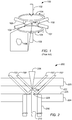
- FIG. 1 shows schematically a typical MOT 100.
- Laser beams 102 slow the neutral atoms and electromagnets 104, which have currents flowing in opposite directions from each other, trap the neutral atoms in a cloud 106.
- an ionizing laser ionizes neutral atoms in the trap, and the ions are extracted by an electric field and accelerated in the form of an ion beam toward a target.
- the cold temperatures in the cloud yield an ion beam with excellent characteristics that theoretically allow for a beam resolution of 10 nm or less.
- the current produced from this source depends on the operating parameters of the magneto-optical trap and can range from single ions on demand to over 100 pA, a much wider range than is possible using conventional ion sources.
- FIG. 9 is a periodic table that shows which elements can be used in various types of ion sources.
- An object of the invention is to provide a method according to claim 12 and apparatus as defined in claim 1 for forming a focused ion beam from non-point ion source.
- a preferred embodiment comprises an electrode configuration that creates an electrostatic potential to accelerate ions from a distributed source of ions to energies of up to tens of kilovolts (kV) while maintaining a low energy spread.
- the electrode configuration accelerates the ions over an extended distance.
- the electrode configuration reduces electrostatic lensing, that is converging or diverging ions in the beam, so that ions leave the electrode substantially collimated.
- the electrode configuration converges or diverges the beam, and can provide a long or short, positive or negative focal length, depending on what is required to optimize the resolution in a given application.
- the ionizing laser can be directed parallel to the ion beam axis or normal to the axis. If the ionizing laser is oriented normal to the ion beam axis, the ions are created along a line normal to the beam axis and the distance of some of the ions from the optical axis makes it more difficult to focus from the ions to a point on the sample. If the ionizing laser is oriented along the beam axis, the ions are created along the optical axis, but because there is an electrical potential gradient across the cloud, ions created at different places in the trap will have different energies as they leave the trap. Ions having different energies will focus at different places, that is, the beam will exhibit chromatic aberration, enlarging the spot size at the target, thereby reducing resolution.
- a small energy spread and high resolution can be obtained.
- ions are to be accelerated to a few keV, as required in most focused ion beam applications, then a small field at the MOT will require either acceleration to occur over a long distance, or a stronger electric field along the beam path away from the source.
- acceleration is to occur over a long distance using conventional electrostatic electrodes made from good conductors, then the area of these electrodes will have to be on the order of the square of the distance separating them in order to ensure field uniformity. This is not preferred because in many applications, the electrode structure would be impractically large. If, instead, the ions are accelerated over a smaller distance, then the beam will experience strong electrostatic lensing.
- Embodiments of the invention address these problems and produce a high resolution beam from an extended ion source.
- Embodiments of the invention provide an electrode structure that extracts ions from source and accelerates the ions, preferably to several keV or 10s of keV.
- the ions coming from the source are preferably substantially collimated or parallel, that is, neither converging nor diverging.
- Substantially collimated means that focal lengths greater than positive 250 mm or less than negative 250 mm are obtained while still accelerating the ions to 2000 eV.
- focal lengths greater than positive 1000 mm or less than negative 1000 mm, or focal lengths greater than positive 10,000 mm or less than negative 10,000 mm are obtained while accelerating an ion beam to 2000 eV.
- the electrodes may act as a lens that more strongly diverges the beam before the final lens. In still other embodiments, the electrodes may act as a converging lens.
- improved resolution is achieved by providing a source electric field across the neutral atom cloud and an extension electric field that continues to accelerate the ions after they leave the region of the source.
- an extension electric field that continues to accelerate the ions after they leave the region of the source.
- curvature of the equipotential lines can be reduced or eliminated, thereby reducing or eliminating lensing.
- essentially equal is meant that the extension field strength is the same as the source field strength to within about 30 percent, more preferably about 20 percent, even more preferably with about 10 percent, and most preferably within about 5 or less percent.
- the source of ions lies between two planar, preferably disk-shaped electrodes.
- the surfaces of these electrodes have a uniform potential applied across them.
- the disks have a sufficiently large diameter so that this potential, in turn, creates a uniform electric field that accelerates the ions towards one of the disks with a hole punched through it.
- the disk with the hole is referred to as the extractor electrode.
- the other disk is referred to as the source electrode.
- the region between the two disk electrodes is referred to as the source region. After passing through the hole the ions enter an extension field region, preferably created by a long tube-shaped resistive electrode.
- This electrode can comprise, for example, a tube made of doped glass that a finite, but low conductivity, or an insulating tube having a preferably uniform resistive coating on its inner or outer surface.
- the resistive coating provides a uniform electric field along the tube's length.
- the length of the tube is many times as large as the disk separation. In preferred embodiments, the tube length is more than 5 times the disk separation, more than 10 times the disk separation, more than 20 times the disk separate, or about 25 times the disk separation.
- a small energy spread in the source may be maintained and lensing is avoided.
- the use of a resistive element allows a uniform field to be created while keeping the electrode structure compact along the direction perpendicular to the beam's propagation.
- a series of electrodes at gradually decreasing potentials are used to create an approximately uniform field with reduced lensing.
- Charged particles are focused when an electric field is radially non-uniform, that is, the electric field along the optical axis is different from the off-axis electric field, so ions toward the edge of the beam are deflected differently from ions on the axis, making the off-axis ions converge or diverge. Focusing occurs, for example, by fringing effects around a hole in an electrode.
- the acceleration electrode reduces or eliminates the fringing by spreading the voltage drop over a greater distance and gradually reducing the potential to near that of the sample.
- preferred embodiments can provide higher resolution than prior art system because of their ability to accelerate a distributed source of ions while simultaneously maintaining a low energy spread and, in some embodiments, avoiding a crossover. It may also find use in other ion beam systems where the source of ions is larger than a few hundred nanometers.
- Preferred embodiments allow the acceleration of lithium ions to energies of up to 10 keV or more while maintaining beam collimation and a source energy spread less than 0.4 eV for a 10 pm ion source size.
- MOTIS 200 includes a MOT to capture and cool neutral atoms, such as chromium or lithium atoms, from an atomic beam.
- a MOTIS is describes in more detail, for example, in US. Pat. Pub. No. 2008/0296483 .
- a MOT is created by the intersection of the six laser beams 202 (4 shown, with unshown beams coming into and out of the page) and the zero of a quadrupolar magnetic field formed by a pair of oppositely oriented ring shaped strong permanent NdFeB magnets (not shown).
- the laser light is created by second harmonic generation of the output of a Ti:Sapphire laser (not shown), which is in turn pumped by a diode pumped solid-state laser (not shown).
- the laser beams are tuned just below the electron energy transition level being used for cooling.
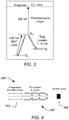
- FIG. 3 shows, for example, relevant energy levels in chromium for cooling and photoionization. When trapping chromium ions, the laser beams are tuned just below the Cr S3 - ⁇ P4 transition at 425 nm.
- a trapped cold chromium atom ensemble or cloud 204 is generally spherically symmetric and has an approximately Gaussian density profile with a standard deviation radius ranging from 50 pm to 500 pm, depending on magnetic field gradient and laser beam intensity, detuning and alignment.
- the temperature of the trapped atoms can be measured by turning off the laser light and allowing the atoms to freely expand for a time.
- the temperature inferred from the rate of expansion of the atomic distribution in one embodiment was 100 ⁇ 15 pK.
- An ionization laser beam 206 is focused through the MOT along the ion beam axis (axial ionization) and has an essentially Gaussian beam waist of standard deviation 5 pm (1/e diameter of 20 pm).
- the ions 210 are extracted in an electric field created by two parallel plates separated by 15 mm, a first plate, source electrode 220, consisting of a fused silica window with a transparent, conducting, coating 222, made from a material such as indium tin oxide (ITO).
- a second plate, extractor plate 224 comprises a silicon electrode about 100 (im thick and having a reflective aluminum coating 226.
- the extractor plate 224 has a hole 228 at the center through which the ions pass.
- the ions are accelerated to their final energy in an acceleration electrode, such as a resistive tube 230, the beginning of which is just below the interior surface of silicon electrode 224, and the far end of which is grounded.
- Resistive tubes are known and can be made, for example, using a doped glass or by providing a resistive coating on the inside of an insulating glass tube.
- a resistive tube electrode is described, for example, in U.S. Pat. No. 5,444,256 to Nagai et al. for an "Electrostatic Lens and Method for Producing the Same" and in U.S. Pat. No. 7,154,086 to Laprade for a "Conductive Tube for Use as a Reflectron Lens.”
- tube 230 is about 265 mm long, with an outer diameter of about 25 mm and an inner diameter of about 125 mm.
- Hole 228 has a diameter of 4 mm and the end of tube 230 is positioned 0.4 mm below the interior surface of plate 224.
- the proximal end of tube 230 may be electrically connected to the interior surface of plate 224.
- the proximal end of tube 230 can be connected to a separate power supply.
- the voltages applied to source electrode 220, the extractor electrode 224, and the opposing ends of tube 230 are chosen so that the electric field in the resistive tube is the same as the uniform electric field between the source electrode 220 and the extractor electrode 224. Because the fields in these two regions are equal, and because the distance between the reflecting aluminum electrode and the start of the resistive tube is small, there is essentially no lensing as the ions pass from the region between the plates into the resistive tube. The ions do however experience a relatively weak diverging lens as they exit the resistive tube. In one embodiment, the free flight distance between the tube exit and the focusing optics is less than 100 mm. Therefore, the ion beam diameter at the focusing lens should be very close to that of the source width, which was typically set to 10pm.
- Acceleration of the ions is determined by the electrical potential difference between the region of the atom ensemble where the ion is created and the target.
- the distal end of the tube electrode is typically at the same potential as the target, that is, at ground potential, although the voltage applied to the distal end of the tube electrode may be different for different applications. Part of the voltage drop, and therefore the acceleration occurs between the source and extractor electrodes and part occurs between the extractor electrode and the distal end of tube 230.
- the distance between the source and extractor electrodes, the length of the tube electrode, and the voltages applied to the electrode are adjusted to produce electric fields that result in the ions that leave the acceleration electrode being substantially collimated. Skilled persons can readily determine appropriate voltages and dimensions for a particular application by simulation, ray tracing, calculation, and experimentation.
- the voltage between the source electrode 220 and the extraction electrode 226 is 100 V, so the ions, which are created on the average midway between the electrodes, emerge through hole 228 with an average energy of 50 eV.
- the voltage across the tube is, for example, 2000 V.
- the source electrode is then biased to 2100 V, so the voltage at the extractor electrode and the top of tube 230 is 2000 V, and the distal end of the tube 230 is grounded.
- most of the ion acceleration occurs outside the extractor electrode and in the acceleration electrode. In some embodiments, more than 50 %, more than 75%, more than 90%, more than 95%, or more than 97.5% of the acceleration occurs outside the extraction electrode.
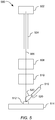
- FIG. 4 shows preferred focusing optics 400 are composed of three parts: a two-axis dipolar deflector 402, a three-element einzel lens 404, and a channel-electron multiplier 406 for secondary electron detection.
- the deflector plate voltage 402 is supplied by a fast amplifier with a range of 100 V and a settling time of 50 ps. The voltage range on the amplifier permits beam deflections from a few nanometers up to a few millimeters.
- FIG. 5 shows schematically a focused ion beam system embodying the present invention.
- Ions are created in a supercold atom ensemble in a MOTIS 502 and are accelerated in acceleration electrode 504 to the desired energy for imaging or processing a target 512.
- Ion beam 506 emerges from the acceleration electrode 504 and is positioned and scanned on the target by deflector 508.
- Objective lens 510 preferably an electrostatic einzel lens, focuses the ion beam 506 onto the target 512, which is positioned on a sample stage 514, preferably a three-axis precision stage.
- Secondary charged particles 520, electrons and ions, are emitted from the target upon impact of the ion beam 506, and the secondary particles are detected by a particle detector 516, such as a scintillator-photomultiplier or a multichannel plate.
- a particle detector 516 such as a scintillator-photomultiplier or a multichannel plate.
- ions were either projected onto targets comprising a microchannel plate and a phosphor screen at a working distance, defined as the distance from the closest surface of the lens to the target, of 28 mm, or onto a sample stage mounted at a working distance of 17 mm. Secondary ion counts from these targets were up to 2x10 5 s' 1 for a 0.2 pA ion beam.
- FIGS. 6A and 6B shows images formed at two different magnifications using a chromium ion beam of a microchannel plate with 10 pm pores an embodiment of the invention.
- the beam energy is 2 keV and the beam size is 250 nm.
- the image is 300 x 300 pixels and was acquired over 90 seconds.
- the 10 pm pores in the plate are clearly resolved, showing good resolution and contrast.
- FIG. 7A and 7B shows images at two different magnifications of the plate created using lithium ion beams with 2 keV beam energy.
- a MOTIS can use any of the elements indicated in FIG. 9 as having suitable electronic transitions for laser cooling, that is, elements that can be readily used in a MOTIS.
- a lithium source is thought to be particularly useful for forming ion beam images. While the preferred embodiment described above uses a MOT source, the invention would be useful in other ion beam systems using an extended source, that is, a non-point source of ions, where the virtual source of ions is larger than a few hundred nanometers.
- one aspect of the invention includes an ion source for providing ions for a focused ion beam directed to a sample on a sample stage, comprising:
- the ions leaving the resistive tube are substantially collimated.
- the substantially collimated ions are produced by the extractor electrode and the resistive tube together converging or diverging the ions to provide a positive or negative ion focal length of magnitude greater than 250 mm, greater than 1000 mm, or greater than 10,000 mm.
- the ions are accelerated in the source region and further accelerated within the resistive tube, the change in energy of the ions caused by the electric field in the resistive tube being at least 10 times the change in energy caused by the electric field in the source region.
- the source region includes a magneto-optical trap for slowing and trapping the neutral atoms.
- the resistive tube extends from within 5 mm of the extractor electrode and in a direction away from the direction of source electrode.
- the resistive tube comprises an insulating tube with a resistive coating.
- the extractor electrode and the resistive tube together converge or diverge the ions or provide a positive or negative ion focal length of magnitude greater than 50 mm.
- Some embodiments of the invention includes an ion source for providing ions for a focused ion beam directed to a sample on a sample stage, comprising:
- the at least one acceleration electrode comprises a resistive tube that extends from near the extractor electrode and away from the source electrode.
- the electrical potential at the end of the resistive tube closest to the extraction electrode differs by less than 20% from the electrical potential as the extraction electrode.
- the resistive tub closest to the extraction electrode is at about the same electrical potential as the extraction electrode.
- the system further comprises an ion focusing lens for focusing the ion beam onto the sample and in which the electrical potential end of the resistive tub furthest from the extraction electrode is at approximately the same electrical potential as the sample.
- the at least one acceleration electrode comprises a series of electrode and further comprising a voltage source for supplying decreasing voltages to the electrodes in the series as the electrode get further from the source region.
- the invention includes an ion source for providing ions for a focused ion beam directed to a sample on a sample stage, comprising:
- the accelerating electrode accelerates the ions over a distance greater than 5 times the size of the source region.
- the invention also encompasses a focused ion beam system comprising any of the ion sources described above, a deflection electrodes for deflecting the ion beam extracted from the source region; and a focusing lens for focusing the ion beam onto a sample on a sample holder.
- the focused ion beam system has no beam-defining apertures positioned between the extraction electrode and the sample holder.
Landscapes
- Chemical & Material Sciences (AREA)
- Analytical Chemistry (AREA)
- Physics & Mathematics (AREA)
- Engineering & Computer Science (AREA)
- Plasma & Fusion (AREA)
- Other Investigation Or Analysis Of Materials By Electrical Means (AREA)
- Electron Sources, Ion Sources (AREA)
Claims (15)
- Source d'ions (200, 502) pour fournir des ions (210, 506) pour un faisceau d'ions focalisé dirigé vers une cible (512), comprenant :une région de source non ponctuelle (204) pour fournir des ions, la région de source non ponctuelle définissant une région de source étendue (204) ;une électrode de source (220) sur un côté de la région de source étendue, l'électrode de source étant configurée pour fournir un potentiel électrique à la région de source étendue ;une électrode d'extraction (224, 226) comportant un trou (228), l'électrode de source et l'électrode d'extraction fournissant, en fonctionnement, un champ électrique pour extraire des ions à partir de la région de source étendue ;une électrode d'accélération (230, 504) pour accélérer les ions provenant de la région de source étendue, etune lentille de focalisation (510) pour focaliser les ions provenant de l'électrode d'accélération sur une cible, l'électrode d'accélération comprend un tube d'électrode (230, 504) configuré pour fournir différents potentiels électriques à différents points le long du tube d'électrode,caractérisée en ce que
l'électrode d'extraction (224, 226) est positionnée sur le côté opposé de la région de source étendue par rapport à l'électrode de source, et l'électrode d'accélération, en fonctionnement, recevant des ions depuis le trou dans l'électrode d'extraction et accélérant les ions. - Source d'ions de la revendication 1 dans laquelle le tube d'électrode est un tube résistif.
- Source d'ions de l'une quelconque des revendications ci-dessus dans laquelle le tube d'électrode s'étend depuis au plus 5 mm de l'électrode d'extraction et dans une direction opposée à la direction de l'électrode de source.
- Source d'ions de l'une quelconque des revendications ci-dessus dans laquelle, en fonctionnement, l'extrémité du tube d'électrode la plus proche de l'électrode d'extraction est sensiblement au même potentiel électrique que l'électrode d'extraction et dans laquelle, en fonctionnement, l'autre extrémité du tube est sensiblement au même potentiel électrique que la cible.
- Source d'ions de la revendication 1 dans laquelle l'électrode d'extraction et le tube d'électrode, conjointement, en fonctionnement, amènent les ions à converger ou diverger pour obtenir une distance focale d'ions positifs ou négatifs ayant une amplitude supérieure à 250 mm.
- Source d'ions de l'une quelconque des revendications ci-dessus dans laquelle la région de source étendue comprend un piège magnéto-optique pour ralentir et piéger les atomes neutres.
- Source d'ions de l'une quelconque des revendications ci-dessus dans laquelle, en fonctionnement, les ions sont accélérés dans la région de source étendue et accélérés plus avant dans le tube d'électrode, le changement d'énergie des ions causé par le champ électrique dans le tube d'électrode étant au moins 10 fois le changement d'énergie causé par le champ électrique dans la région de source.
- Source d'ions de l'une quelconque des revendications ci-dessus dans laquelle l'électrode de source étendue et l'électrode d'extraction sont des électrodes planes et la longueur du tube d'électrode étant au moins cinq fois la séparation des plans.
- Source d'ions de l'une quelconque des revendications ci-dessus dans laquelle, en fonctionnement, l'électrode d'accélération fournit un champ électrique d'extension s'étendant depuis l'électrode d'extraction, l'intensité du champ électrique d'extension juste au-delà du trou dans l'électrode d'extraction différant de l'intensité du champ électrique de source de moins de trente pour cent, de façon à réduire ou éliminer les effets de focalisation lorsque les ions quittent la région de source étendue.
- Source d'ions de l'une quelconque des revendications 1 ou 3 à 9 dans laquelle le tube d'électrode comprend une série d'électrodes qui, en fonctionnement, sont à des potentiels décroissant progressivement pour créer un champ approximativement uniforme avec un ensemble de lentilles réduit.
- Système de faisceau d'ions focalisé, comprenant :une source d'ions selon l'une quelconque des revendications ci-dessus ; etdes électrodes de déviation pour dévier le faisceau d'ions extrait depuis la région de source étendue.
- Procédé de formation d'un faisceau de particules chargées, comprenant :la fourniture d'ions à partir d'une région de source d'ions non ponctuelle, la région de source d'ions non ponctuelle définissant une région de source étendue ;la fourniture d'un potentiel électrique à la région de source étendue avec une électrode de source, l'électrode de source étant positionnée sur un côté de la région de source étendue ;la fourniture d'un champ électrique avec l'électrode de source et une électrode d'extraction pour extraire des ions à partir de la région de source étendue à travers un trou dans l'extracteur accélérant les ions provenant de la région de source étendue au moyen d'une électrode d'accélération ; etl'utilisation d'une lentille de focalisation pour focaliser les ions provenant de la région de source étendue sur une cible,l'accélération des ions provenant de la région de source étendue comprend la fourniture de différents potentiels électriques à différents points le long d'un tube d'électrode, le tube d'électrode étant compris dans l'électrode d'accélération,caractérisée en ce que
l'électrode d'extraction est positionnée sur le côté opposé de la région de source étendue par rapport à l'électrode de source ; et l'électrode d'accélération recevant les ions provenant du trou dans l'électrode d'extraction et accélérant les ions dans le tube d'électrode. - Procédé de la revendication 12 dans lequel l'extrémité du tube d'électrode la plus proche de l'électrode d'extraction est sensiblement au même potentiel électrique que l'électrode d'extraction et dans lequel, en fonctionnement, l'autre extrémité du tube est sensiblement au même potentiel électrique que la cible.
- Procédé de la revendication 12 dans lequel l'électrode d'accélération fournit un champ électrique d'extension s'étendant depuis l'électrode d'extraction, l'intensité du champ électrique d'extension juste au-delà du trou dans l'électrode d'extraction différant de l'intensité du champ électrique de source de moins de trente pour cent, de façon à réduire ou éliminer les effets de focalisation lorsque les ions quittent la région de source.
- Procédé de la revendication 12 dans lequel la région de source comprend un piège magnéto-optique pour ralentir et piéger des atomes neutres ultra-froids.
Applications Claiming Priority (2)
| Application Number | Priority Date | Filing Date | Title |
|---|---|---|---|
| US24357209P | 2009-09-18 | 2009-09-18 | |
| PCT/US2010/049525 WO2011035260A2 (fr) | 2009-09-18 | 2010-09-20 | Colonne d'accélération de source ionique distribuée |
Publications (3)
| Publication Number | Publication Date |
|---|---|
| EP2478546A2 EP2478546A2 (fr) | 2012-07-25 |
| EP2478546A4 EP2478546A4 (fr) | 2014-07-30 |
| EP2478546B1 true EP2478546B1 (fr) | 2018-07-04 |
Family
ID=43759311
Family Applications (1)
| Application Number | Title | Priority Date | Filing Date |
|---|---|---|---|
| EP10817985.4A Active EP2478546B1 (fr) | 2009-09-18 | 2010-09-20 | Colonne d'accélération de source ionique distribuée |
Country Status (5)
| Country | Link |
|---|---|
| US (1) | US8314404B2 (fr) |
| EP (1) | EP2478546B1 (fr) |
| JP (1) | JP5794990B2 (fr) |
| CN (1) | CN102598195B (fr) |
| WO (1) | WO2011035260A2 (fr) |
Families Citing this family (9)
| Publication number | Priority date | Publication date | Assignee | Title |
|---|---|---|---|---|
| WO2011035260A2 (fr) | 2009-09-18 | 2011-03-24 | Fei Company | Colonne d'accélération de source ionique distribuée |
| US8519355B2 (en) | 2011-10-07 | 2013-08-27 | Carl Zeiss Microscopy Gmbh | Charged particle source |
| US8933414B2 (en) * | 2013-02-27 | 2015-01-13 | Fei Company | Focused ion beam low kV enhancement |
| WO2015137150A1 (fr) * | 2014-03-12 | 2015-09-17 | 株式会社アルバック | Dispositif et procédé de rayonnement ionique |
| US20160042914A1 (en) * | 2014-08-07 | 2016-02-11 | Frederick Wight Martin | Achromatic dual-fib instrument for microfabrication and microanalysis |
| US10371763B2 (en) * | 2015-07-17 | 2019-08-06 | Honeywell International Inc. | Systems and methods for low power magnetic field generation for atomic sensors using electro-permanent magnets |
| KR101967145B1 (ko) * | 2017-04-06 | 2019-04-09 | 울박, 인크 | 이온원 및 이온 주입 장치 |
| CN107219182B (zh) * | 2017-07-14 | 2019-08-20 | 宜昌后皇真空科技有限公司 | 粒子束激发真空紫外-可见光波段磁光谱测试方法及系统 |
| CN109411321B (zh) * | 2018-10-29 | 2021-02-12 | 中国船舶重工集团公司第七0七研究所 | 一种应用于离子束刻蚀溅射防护的装置和方法 |
Family Cites Families (28)
| Publication number | Priority date | Publication date | Assignee | Title |
|---|---|---|---|---|
| US8029A (en) * | 1851-04-08 | Kellogg | ||
| BE440927A (fr) * | 1940-05-08 | |||
| US4126781A (en) * | 1977-05-10 | 1978-11-21 | Extranuclear Laboratories, Inc. | Method and apparatus for producing electrostatic fields by surface currents on resistive materials with applications to charged particle optics and energy analysis |
| US4370594A (en) * | 1978-11-29 | 1983-01-25 | Rca Corporation | Resistive lens structure for electron gun |
| JPH0750638B2 (ja) * | 1986-03-28 | 1995-05-31 | 理化学研究所 | 電界発生装置 |
| JPS63119199A (ja) * | 1986-11-07 | 1988-05-23 | 日本真空技術株式会社 | イオンビーム用静電加速器 |
| JPH0268835A (ja) * | 1988-09-02 | 1990-03-08 | Mitsubishi Electric Corp | イオン源 |
| JPH02288048A (ja) * | 1989-04-27 | 1990-11-28 | Nec Corp | 光イオン化イオン源 |
| JPH0325845A (ja) * | 1989-06-21 | 1991-02-04 | Jeol Ltd | 荷電粒子ビーム加速管のコンディショニング装置 |
| JPH03134946A (ja) * | 1989-10-19 | 1991-06-07 | Sony Corp | イオン注入装置 |
| JPH0472600U (fr) * | 1990-11-06 | 1992-06-25 | ||
| JPH05114383A (ja) * | 1991-10-19 | 1993-05-07 | Ulvac Japan Ltd | マイクロイオンビーム形成装置 |
| JP2897549B2 (ja) * | 1992-10-05 | 1999-05-31 | 日産自動車株式会社 | 原子状酸素ビーム発生装置 |
| JP3090802B2 (ja) | 1992-12-17 | 2000-09-25 | 株式会社東芝 | 静電レンズおよびその製造方法 |
| JPH11288800A (ja) * | 1998-04-01 | 1999-10-19 | Nissin High Voltage Co Ltd | 加速管 |
| JP3763446B2 (ja) | 1999-10-18 | 2006-04-05 | キヤノン株式会社 | 静電レンズ、電子ビーム描画装置、荷電ビーム応用装置、および、デバイス製造方法 |
| US6495844B1 (en) * | 2000-01-25 | 2002-12-17 | Welch Allyn, Inc. | Metal halide lamp for curing adhesives |
| JP3449473B2 (ja) * | 2000-01-28 | 2003-09-22 | 理化学研究所 | 低速多価イオンビームの発生装置 |
| JP3972972B2 (ja) | 2000-06-02 | 2007-09-05 | 独立行政法人科学技術振興機構 | 原子ビーム発生方法及び装置 |
| US6943347B1 (en) | 2002-10-18 | 2005-09-13 | Ross Clark Willoughby | Laminated tube for the transport of charged particles contained in a gaseous medium |
| US7154086B2 (en) * | 2003-03-19 | 2006-12-26 | Burle Technologies, Inc. | Conductive tube for use as a reflectron lens |
| US6953928B2 (en) * | 2003-10-31 | 2005-10-11 | Applera Corporation | Ion source and methods for MALDI mass spectrometry |
| KR20070034569A (ko) * | 2004-06-04 | 2007-03-28 | 메사추세츠 인스티튜트 오브 테크놀로지 | 비축대칭 하전 입자 빔 시스템 |
| JP2006331691A (ja) * | 2005-05-23 | 2006-12-07 | Kobe Steel Ltd | イオン照射装置,イオン照射方法 |
| US7709807B2 (en) | 2007-05-31 | 2010-05-04 | United States Of America As Represented By The Secretary Of Commerce, The National Institute Of Standards And Technology | Magneto-optical trap ion source |
| US7863582B2 (en) * | 2008-01-25 | 2011-01-04 | Valery Godyak | Ion-beam source |
| WO2011035260A2 (fr) | 2009-09-18 | 2011-03-24 | Fei Company | Colonne d'accélération de source ionique distribuée |
| JP5023199B2 (ja) * | 2010-07-29 | 2012-09-12 | 株式会社日立ハイテクノロジーズ | 荷電粒子線放射装置 |
-
2010
- 2010-09-20 WO PCT/US2010/049525 patent/WO2011035260A2/fr not_active Ceased
- 2010-09-20 CN CN201080041464.7A patent/CN102598195B/zh active Active
- 2010-09-20 JP JP2012529965A patent/JP5794990B2/ja active Active
- 2010-09-20 US US12/886,354 patent/US8314404B2/en active Active
- 2010-09-20 EP EP10817985.4A patent/EP2478546B1/fr active Active
Non-Patent Citations (1)
| Title |
|---|
| None * |
Also Published As
| Publication number | Publication date |
|---|---|
| US8314404B2 (en) | 2012-11-20 |
| WO2011035260A2 (fr) | 2011-03-24 |
| CN102598195B (zh) | 2015-09-16 |
| EP2478546A2 (fr) | 2012-07-25 |
| WO2011035260A4 (fr) | 2011-07-14 |
| WO2011035260A3 (fr) | 2011-05-19 |
| JP2013505545A (ja) | 2013-02-14 |
| US20110210264A1 (en) | 2011-09-01 |
| CN102598195A (zh) | 2012-07-18 |
| JP5794990B2 (ja) | 2015-10-14 |
| EP2478546A4 (fr) | 2014-07-30 |
Similar Documents
| Publication | Publication Date | Title |
|---|---|---|
| EP2478546B1 (fr) | Colonne d'accélération de source ionique distribuée | |
| JP5970498B2 (ja) | デュアルビームシステム及びその制御方法 | |
| EP2365514B1 (fr) | Colonne de particules chargées de faisceau double et son procédé de contrôle | |
| EP1045425B1 (fr) | Appareil à faisceaux de particules chargées avec compensation de l'aberration chromatique | |
| US8785879B1 (en) | Electron beam wafer inspection system and method of operation thereof | |
| US20070215802A1 (en) | Systems and methods for a gas field ion microscope | |
| US9570268B2 (en) | Electron gun, charged particle gun, and charged particle beam apparatus using electron gun and charged particle gun | |
| US8933414B2 (en) | Focused ion beam low kV enhancement | |
| EP4376047A2 (fr) | Système à faisceau de particules | |
| JP2020074329A (ja) | 電子ビーム画像化装置及び方法 | |
| CN108807118A (zh) | 一种扫描电子显微镜系统及样品探测方法 | |
| US11004649B2 (en) | Ion source device | |
| KR20190138898A (ko) | 멀티 빔 컬럼 내에서의 감소된 쿨롱 상호작용 | |
| US8049180B2 (en) | Achromatic mass separator | |
| JP4343951B2 (ja) | 荷電粒子ビーム系用の単段式荷電粒子ビームエネルギー幅低減系 | |
| US9245709B1 (en) | Charged particle beam specimen inspection system and method for operation thereof | |
| JP6261228B2 (ja) | 集束イオンビーム装置、集束イオン/電子ビーム加工観察装置、及び試料加工方法 | |
| AU689528B2 (en) | Chromatically compensated particle-beam column | |
| WO2009141655A2 (fr) | Générateur de faisceau de particules amélioré | |
| Menon et al. | Simulation of ion beam optics for focused ion beam system |
Legal Events
| Date | Code | Title | Description |
|---|---|---|---|
| PUAI | Public reference made under article 153(3) epc to a published international application that has entered the european phase |
Free format text: ORIGINAL CODE: 0009012 |
|
| 17P | Request for examination filed |
Effective date: 20120315 |
|
| AK | Designated contracting states |
Kind code of ref document: A2 Designated state(s): AL AT BE BG CH CY CZ DE DK EE ES FI FR GB GR HR HU IE IS IT LI LT LU LV MC MK MT NL NO PL PT RO SE SI SK SM TR |
|
| DAX | Request for extension of the european patent (deleted) | ||
| REG | Reference to a national code |
Ref country code: DE Ref legal event code: R079 Ref document number: 602010051709 Country of ref document: DE Free format text: PREVIOUS MAIN CLASS: H01J0027020000 Ipc: H01J0037040000 |
|
| A4 | Supplementary search report drawn up and despatched |
Effective date: 20140627 |
|
| RIC1 | Information provided on ipc code assigned before grant |
Ipc: H01J 37/08 20060101ALI20140623BHEP Ipc: H01J 27/02 20060101ALI20140623BHEP Ipc: H01J 37/04 20060101AFI20140623BHEP Ipc: H01J 37/305 20060101ALI20140623BHEP |
|
| STAA | Information on the status of an ep patent application or granted ep patent |
Free format text: STATUS: EXAMINATION IS IN PROGRESS |
|
| 17Q | First examination report despatched |
Effective date: 20170606 |
|
| GRAP | Despatch of communication of intention to grant a patent |
Free format text: ORIGINAL CODE: EPIDOSNIGR1 |
|
| STAA | Information on the status of an ep patent application or granted ep patent |
Free format text: STATUS: GRANT OF PATENT IS INTENDED |
|
| INTG | Intention to grant announced |
Effective date: 20180409 |
|
| GRAS | Grant fee paid |
Free format text: ORIGINAL CODE: EPIDOSNIGR3 |
|
| GRAA | (expected) grant |
Free format text: ORIGINAL CODE: 0009210 |
|
| STAA | Information on the status of an ep patent application or granted ep patent |
Free format text: STATUS: THE PATENT HAS BEEN GRANTED |
|
| AK | Designated contracting states |
Kind code of ref document: B1 Designated state(s): AL AT BE BG CH CY CZ DE DK EE ES FI FR GB GR HR HU IE IS IT LI LT LU LV MC MK MT NL NO PL PT RO SE SI SK SM TR |
|
| REG | Reference to a national code |
Ref country code: GB Ref legal event code: FG4D |
|
| REG | Reference to a national code |
Ref country code: CH Ref legal event code: EP |
|
| REG | Reference to a national code |
Ref country code: AT Ref legal event code: REF Ref document number: 1015407 Country of ref document: AT Kind code of ref document: T Effective date: 20180715 |
|
| REG | Reference to a national code |
Ref country code: IE Ref legal event code: FG4D |
|
| REG | Reference to a national code |
Ref country code: DE Ref legal event code: R096 Ref document number: 602010051709 Country of ref document: DE |
|
| REG | Reference to a national code |
Ref country code: NL Ref legal event code: MP Effective date: 20180704 |
|
| REG | Reference to a national code |
Ref country code: LT Ref legal event code: MG4D |
|
| REG | Reference to a national code |
Ref country code: AT Ref legal event code: MK05 Ref document number: 1015407 Country of ref document: AT Kind code of ref document: T Effective date: 20180704 |
|
| PG25 | Lapsed in a contracting state [announced via postgrant information from national office to epo] |
Ref country code: NL Free format text: LAPSE BECAUSE OF FAILURE TO SUBMIT A TRANSLATION OF THE DESCRIPTION OR TO PAY THE FEE WITHIN THE PRESCRIBED TIME-LIMIT Effective date: 20180704 |
|
| PG25 | Lapsed in a contracting state [announced via postgrant information from national office to epo] |
Ref country code: NO Free format text: LAPSE BECAUSE OF FAILURE TO SUBMIT A TRANSLATION OF THE DESCRIPTION OR TO PAY THE FEE WITHIN THE PRESCRIBED TIME-LIMIT Effective date: 20181004 Ref country code: BG Free format text: LAPSE BECAUSE OF FAILURE TO SUBMIT A TRANSLATION OF THE DESCRIPTION OR TO PAY THE FEE WITHIN THE PRESCRIBED TIME-LIMIT Effective date: 20181004 Ref country code: AT Free format text: LAPSE BECAUSE OF FAILURE TO SUBMIT A TRANSLATION OF THE DESCRIPTION OR TO PAY THE FEE WITHIN THE PRESCRIBED TIME-LIMIT Effective date: 20180704 Ref country code: CZ Free format text: LAPSE BECAUSE OF FAILURE TO SUBMIT A TRANSLATION OF THE DESCRIPTION OR TO PAY THE FEE WITHIN THE PRESCRIBED TIME-LIMIT Effective date: 20180704 Ref country code: LT Free format text: LAPSE BECAUSE OF FAILURE TO SUBMIT A TRANSLATION OF THE DESCRIPTION OR TO PAY THE FEE WITHIN THE PRESCRIBED TIME-LIMIT Effective date: 20180704 Ref country code: IS Free format text: LAPSE BECAUSE OF FAILURE TO SUBMIT A TRANSLATION OF THE DESCRIPTION OR TO PAY THE FEE WITHIN THE PRESCRIBED TIME-LIMIT Effective date: 20181104 Ref country code: PL Free format text: LAPSE BECAUSE OF FAILURE TO SUBMIT A TRANSLATION OF THE DESCRIPTION OR TO PAY THE FEE WITHIN THE PRESCRIBED TIME-LIMIT Effective date: 20180704 Ref country code: GR Free format text: LAPSE BECAUSE OF FAILURE TO SUBMIT A TRANSLATION OF THE DESCRIPTION OR TO PAY THE FEE WITHIN THE PRESCRIBED TIME-LIMIT Effective date: 20181005 Ref country code: FI Free format text: LAPSE BECAUSE OF FAILURE TO SUBMIT A TRANSLATION OF THE DESCRIPTION OR TO PAY THE FEE WITHIN THE PRESCRIBED TIME-LIMIT Effective date: 20180704 Ref country code: SE Free format text: LAPSE BECAUSE OF FAILURE TO SUBMIT A TRANSLATION OF THE DESCRIPTION OR TO PAY THE FEE WITHIN THE PRESCRIBED TIME-LIMIT Effective date: 20180704 |
|
| PG25 | Lapsed in a contracting state [announced via postgrant information from national office to epo] |
Ref country code: AL Free format text: LAPSE BECAUSE OF FAILURE TO SUBMIT A TRANSLATION OF THE DESCRIPTION OR TO PAY THE FEE WITHIN THE PRESCRIBED TIME-LIMIT Effective date: 20180704 Ref country code: ES Free format text: LAPSE BECAUSE OF FAILURE TO SUBMIT A TRANSLATION OF THE DESCRIPTION OR TO PAY THE FEE WITHIN THE PRESCRIBED TIME-LIMIT Effective date: 20180704 Ref country code: LV Free format text: LAPSE BECAUSE OF FAILURE TO SUBMIT A TRANSLATION OF THE DESCRIPTION OR TO PAY THE FEE WITHIN THE PRESCRIBED TIME-LIMIT Effective date: 20180704 Ref country code: HR Free format text: LAPSE BECAUSE OF FAILURE TO SUBMIT A TRANSLATION OF THE DESCRIPTION OR TO PAY THE FEE WITHIN THE PRESCRIBED TIME-LIMIT Effective date: 20180704 |
|
| REG | Reference to a national code |
Ref country code: DE Ref legal event code: R097 Ref document number: 602010051709 Country of ref document: DE |
|
| PG25 | Lapsed in a contracting state [announced via postgrant information from national office to epo] |
Ref country code: EE Free format text: LAPSE BECAUSE OF FAILURE TO SUBMIT A TRANSLATION OF THE DESCRIPTION OR TO PAY THE FEE WITHIN THE PRESCRIBED TIME-LIMIT Effective date: 20180704 Ref country code: MC Free format text: LAPSE BECAUSE OF FAILURE TO SUBMIT A TRANSLATION OF THE DESCRIPTION OR TO PAY THE FEE WITHIN THE PRESCRIBED TIME-LIMIT Effective date: 20180704 Ref country code: IT Free format text: LAPSE BECAUSE OF FAILURE TO SUBMIT A TRANSLATION OF THE DESCRIPTION OR TO PAY THE FEE WITHIN THE PRESCRIBED TIME-LIMIT Effective date: 20180704 Ref country code: RO Free format text: LAPSE BECAUSE OF FAILURE TO SUBMIT A TRANSLATION OF THE DESCRIPTION OR TO PAY THE FEE WITHIN THE PRESCRIBED TIME-LIMIT Effective date: 20180704 |
|
| REG | Reference to a national code |
Ref country code: CH Ref legal event code: PL |
|
| PLBE | No opposition filed within time limit |
Free format text: ORIGINAL CODE: 0009261 |
|
| STAA | Information on the status of an ep patent application or granted ep patent |
Free format text: STATUS: NO OPPOSITION FILED WITHIN TIME LIMIT |
|
| PG25 | Lapsed in a contracting state [announced via postgrant information from national office to epo] |
Ref country code: SM Free format text: LAPSE BECAUSE OF FAILURE TO SUBMIT A TRANSLATION OF THE DESCRIPTION OR TO PAY THE FEE WITHIN THE PRESCRIBED TIME-LIMIT Effective date: 20180704 Ref country code: DK Free format text: LAPSE BECAUSE OF FAILURE TO SUBMIT A TRANSLATION OF THE DESCRIPTION OR TO PAY THE FEE WITHIN THE PRESCRIBED TIME-LIMIT Effective date: 20180704 Ref country code: SK Free format text: LAPSE BECAUSE OF FAILURE TO SUBMIT A TRANSLATION OF THE DESCRIPTION OR TO PAY THE FEE WITHIN THE PRESCRIBED TIME-LIMIT Effective date: 20180704 |
|
| 26N | No opposition filed |
Effective date: 20190405 |
|
| REG | Reference to a national code |
Ref country code: BE Ref legal event code: MM Effective date: 20180930 |
|
| GBPC | Gb: european patent ceased through non-payment of renewal fee |
Effective date: 20181004 |
|
| REG | Reference to a national code |
Ref country code: IE Ref legal event code: MM4A |
|
| PG25 | Lapsed in a contracting state [announced via postgrant information from national office to epo] |
Ref country code: LU Free format text: LAPSE BECAUSE OF NON-PAYMENT OF DUE FEES Effective date: 20180920 |
|
| PG25 | Lapsed in a contracting state [announced via postgrant information from national office to epo] |
Ref country code: IE Free format text: LAPSE BECAUSE OF NON-PAYMENT OF DUE FEES Effective date: 20180920 |
|
| PG25 | Lapsed in a contracting state [announced via postgrant information from national office to epo] |
Ref country code: BE Free format text: LAPSE BECAUSE OF NON-PAYMENT OF DUE FEES Effective date: 20180930 Ref country code: CH Free format text: LAPSE BECAUSE OF NON-PAYMENT OF DUE FEES Effective date: 20180930 Ref country code: LI Free format text: LAPSE BECAUSE OF NON-PAYMENT OF DUE FEES Effective date: 20180930 Ref country code: SI Free format text: LAPSE BECAUSE OF FAILURE TO SUBMIT A TRANSLATION OF THE DESCRIPTION OR TO PAY THE FEE WITHIN THE PRESCRIBED TIME-LIMIT Effective date: 20180704 Ref country code: FR Free format text: LAPSE BECAUSE OF NON-PAYMENT OF DUE FEES Effective date: 20180930 |
|
| PG25 | Lapsed in a contracting state [announced via postgrant information from national office to epo] |
Ref country code: GB Free format text: LAPSE BECAUSE OF NON-PAYMENT OF DUE FEES Effective date: 20181004 |
|
| PG25 | Lapsed in a contracting state [announced via postgrant information from national office to epo] |
Ref country code: MT Free format text: LAPSE BECAUSE OF NON-PAYMENT OF DUE FEES Effective date: 20180920 |
|
| PG25 | Lapsed in a contracting state [announced via postgrant information from national office to epo] |
Ref country code: TR Free format text: LAPSE BECAUSE OF FAILURE TO SUBMIT A TRANSLATION OF THE DESCRIPTION OR TO PAY THE FEE WITHIN THE PRESCRIBED TIME-LIMIT Effective date: 20180704 |
|
| PG25 | Lapsed in a contracting state [announced via postgrant information from national office to epo] |
Ref country code: PT Free format text: LAPSE BECAUSE OF FAILURE TO SUBMIT A TRANSLATION OF THE DESCRIPTION OR TO PAY THE FEE WITHIN THE PRESCRIBED TIME-LIMIT Effective date: 20180704 Ref country code: HU Free format text: LAPSE BECAUSE OF FAILURE TO SUBMIT A TRANSLATION OF THE DESCRIPTION OR TO PAY THE FEE WITHIN THE PRESCRIBED TIME-LIMIT; INVALID AB INITIO Effective date: 20100920 |
|
| PG25 | Lapsed in a contracting state [announced via postgrant information from national office to epo] |
Ref country code: MK Free format text: LAPSE BECAUSE OF NON-PAYMENT OF DUE FEES Effective date: 20180704 Ref country code: CY Free format text: LAPSE BECAUSE OF FAILURE TO SUBMIT A TRANSLATION OF THE DESCRIPTION OR TO PAY THE FEE WITHIN THE PRESCRIBED TIME-LIMIT Effective date: 20180704 |
|
| PGFP | Annual fee paid to national office [announced via postgrant information from national office to epo] |
Ref country code: DE Payment date: 20250820 Year of fee payment: 16 |