EP2479351A1 - Machine de construction hybride - Google Patents
Machine de construction hybride Download PDFInfo
- Publication number
- EP2479351A1 EP2479351A1 EP10817174A EP10817174A EP2479351A1 EP 2479351 A1 EP2479351 A1 EP 2479351A1 EP 10817174 A EP10817174 A EP 10817174A EP 10817174 A EP10817174 A EP 10817174A EP 2479351 A1 EP2479351 A1 EP 2479351A1
- Authority
- EP
- European Patent Office
- Prior art keywords
- hydraulic pump
- pump
- motor
- hydraulic
- boom
- Prior art date
- Legal status (The legal status is an assumption and is not a legal conclusion. Google has not performed a legal analysis and makes no representation as to the accuracy of the status listed.)
- Withdrawn
Links
Images


Classifications
-
- E—FIXED CONSTRUCTIONS
- E02—HYDRAULIC ENGINEERING; FOUNDATIONS; SOIL SHIFTING
- E02F—DREDGING; SOIL-SHIFTING
- E02F9/00—Component parts of dredgers or soil-shifting machines, not restricted to one of the kinds covered by groups E02F3/00 - E02F7/00
- E02F9/20—Drives; Control devices
- E02F9/22—Hydraulic or pneumatic drives
- E02F9/2278—Hydraulic circuits
- E02F9/2296—Systems with a variable displacement pump
-
- E—FIXED CONSTRUCTIONS
- E02—HYDRAULIC ENGINEERING; FOUNDATIONS; SOIL SHIFTING
- E02F—DREDGING; SOIL-SHIFTING
- E02F3/00—Dredgers; Soil-shifting machines
- E02F3/04—Dredgers; Soil-shifting machines mechanically-driven
- E02F3/28—Dredgers; Soil-shifting machines mechanically-driven with digging tools mounted on a dipper- or bucket-arm, i.e. there is either one arm or a pair of arms, e.g. dippers, buckets
- E02F3/36—Component parts
- E02F3/42—Drives for dippers, buckets, dipper-arms or bucket-arms
- E02F3/43—Control of dipper or bucket position; Control of sequence of drive operations
-
- B—PERFORMING OPERATIONS; TRANSPORTING
- B60—VEHICLES IN GENERAL
- B60K—ARRANGEMENT OR MOUNTING OF PROPULSION UNITS OR OF TRANSMISSIONS IN VEHICLES; ARRANGEMENT OR MOUNTING OF PLURAL DIVERSE PRIME-MOVERS IN VEHICLES; AUXILIARY DRIVES FOR VEHICLES; INSTRUMENTATION OR DASHBOARDS FOR VEHICLES; ARRANGEMENTS IN CONNECTION WITH COOLING, AIR INTAKE, GAS EXHAUST OR FUEL SUPPLY OF PROPULSION UNITS IN VEHICLES
- B60K6/00—Arrangement or mounting of plural diverse prime-movers for mutual or common propulsion, e.g. hybrid propulsion systems comprising electric motors and internal combustion engines
- B60K6/20—Arrangement or mounting of plural diverse prime-movers for mutual or common propulsion, e.g. hybrid propulsion systems comprising electric motors and internal combustion engines the prime-movers consisting of electric motors and internal combustion engines, e.g. HEVs
- B60K6/42—Arrangement or mounting of plural diverse prime-movers for mutual or common propulsion, e.g. hybrid propulsion systems comprising electric motors and internal combustion engines the prime-movers consisting of electric motors and internal combustion engines, e.g. HEVs characterised by the architecture of the hybrid electric vehicle
- B60K6/46—Series type
-
- E—FIXED CONSTRUCTIONS
- E02—HYDRAULIC ENGINEERING; FOUNDATIONS; SOIL SHIFTING
- E02F—DREDGING; SOIL-SHIFTING
- E02F9/00—Component parts of dredgers or soil-shifting machines, not restricted to one of the kinds covered by groups E02F3/00 - E02F7/00
- E02F9/20—Drives; Control devices
-
- E—FIXED CONSTRUCTIONS
- E02—HYDRAULIC ENGINEERING; FOUNDATIONS; SOIL SHIFTING
- E02F—DREDGING; SOIL-SHIFTING
- E02F9/00—Component parts of dredgers or soil-shifting machines, not restricted to one of the kinds covered by groups E02F3/00 - E02F7/00
- E02F9/20—Drives; Control devices
- E02F9/2058—Electric or electro-mechanical or mechanical control devices of vehicle sub-units
- E02F9/2062—Control of propulsion units
- E02F9/2075—Control of propulsion units of the hybrid type
-
- E—FIXED CONSTRUCTIONS
- E02—HYDRAULIC ENGINEERING; FOUNDATIONS; SOIL SHIFTING
- E02F—DREDGING; SOIL-SHIFTING
- E02F9/00—Component parts of dredgers or soil-shifting machines, not restricted to one of the kinds covered by groups E02F3/00 - E02F7/00
- E02F9/20—Drives; Control devices
- E02F9/22—Hydraulic or pneumatic drives
- E02F9/2221—Control of flow rate; Load sensing arrangements
- E02F9/2232—Control of flow rate; Load sensing arrangements using one or more variable displacement pumps
- E02F9/2235—Control of flow rate; Load sensing arrangements using one or more variable displacement pumps including an electronic controller
-
- E—FIXED CONSTRUCTIONS
- E02—HYDRAULIC ENGINEERING; FOUNDATIONS; SOIL SHIFTING
- E02F—DREDGING; SOIL-SHIFTING
- E02F9/00—Component parts of dredgers or soil-shifting machines, not restricted to one of the kinds covered by groups E02F3/00 - E02F7/00
- E02F9/20—Drives; Control devices
- E02F9/22—Hydraulic or pneumatic drives
- E02F9/2221—Control of flow rate; Load sensing arrangements
- E02F9/2239—Control of flow rate; Load sensing arrangements using two or more pumps with cross-assistance
- E02F9/2242—Control of flow rate; Load sensing arrangements using two or more pumps with cross-assistance including an electronic controller
-
- E—FIXED CONSTRUCTIONS
- E02—HYDRAULIC ENGINEERING; FOUNDATIONS; SOIL SHIFTING
- E02F—DREDGING; SOIL-SHIFTING
- E02F9/00—Component parts of dredgers or soil-shifting machines, not restricted to one of the kinds covered by groups E02F3/00 - E02F7/00
- E02F9/20—Drives; Control devices
- E02F9/22—Hydraulic or pneumatic drives
- E02F9/2278—Hydraulic circuits
- E02F9/2282—Systems using center bypass type changeover valves
-
- E—FIXED CONSTRUCTIONS
- E02—HYDRAULIC ENGINEERING; FOUNDATIONS; SOIL SHIFTING
- E02F—DREDGING; SOIL-SHIFTING
- E02F9/00—Component parts of dredgers or soil-shifting machines, not restricted to one of the kinds covered by groups E02F3/00 - E02F7/00
- E02F9/20—Drives; Control devices
- E02F9/22—Hydraulic or pneumatic drives
- E02F9/2278—Hydraulic circuits
- E02F9/2292—Systems with two or more pumps
-
- Y—GENERAL TAGGING OF NEW TECHNOLOGICAL DEVELOPMENTS; GENERAL TAGGING OF CROSS-SECTIONAL TECHNOLOGIES SPANNING OVER SEVERAL SECTIONS OF THE IPC; TECHNICAL SUBJECTS COVERED BY FORMER USPC CROSS-REFERENCE ART COLLECTIONS [XRACs] AND DIGESTS
- Y02—TECHNOLOGIES OR APPLICATIONS FOR MITIGATION OR ADAPTATION AGAINST CLIMATE CHANGE
- Y02T—CLIMATE CHANGE MITIGATION TECHNOLOGIES RELATED TO TRANSPORTATION
- Y02T10/00—Road transport of goods or passengers
- Y02T10/60—Other road transportation technologies with climate change mitigation effect
- Y02T10/62—Hybrid vehicles
Definitions
- the present invention is related to a hybrid-type construction machine in which a part of driven mechanism is motorized.
- JP2007-10006 A discloses the hybrid-type construction machine in which a part of driven mechanism is motorized.
- an engine is directly coupled to a motor generator which functions as an electric motor and a generator, and a rotating shaft of the motor generator is connected to rotating shafts of first and second variable displacement pumps in series.
- a third variable displacement pump which is driven by the motor generator is provided separately.
- the first pump mainly supplies fluid in a tank to a boom cylinder circuit for controlling a boom cylinder;
- the second pump mainly supplies fluid in the tank to an arm cylinder circuit for controlling an arm cylinder;
- the third pump supplies fluid in the tank to a turning motor circuit for controlling a turning motor.
- a discharge port of the third pump is connected to a pressure fluid replenishing circuit for replenishing pressure fluid to the boom cylinder circuit and the arm cylinder circuit.
- an object of the present invention is to provide a hybrid-type construction machine in which two pumps are arranged effectively.
- a hybrid-type construction machine which comprises an engine; an electric power accumulator; first and second pumps; an electric motor for driving the first pump; and plural actuators which are driven by the first and second pumps, wherein the first and second pumps are arranged such that the first pump controls at least one of the actuators independently from the second pump and the second pump controls at least another one of the actuators independently from the first pump; the first pump is electrically driven by the electric motor using electric power from the electric power accumulator; and the second pump is directly coupled to the engine.
- Fig. 1 is a diagram of a main configuration for illustrating a feature configuration of a hybrid-type construction machine 100 according to the present invention. It is noted that the hybrid-type construction machine 100 may of any type including a hydraulic shovel, a lifting magnet, etc.
- connections related to mechanical power are indicated by double lines
- hydraulic lines are indicated by solid lines
- connections related to electrical drive are indicated by bold lines.
- the hybrid-type construction machine 100 includes an engine 11 which is an internal combustion engine.
- the engine 11 is mechanically and directly coupled to a motor generator (M/G) 12.
- M/G motor generator
- a rotating shaft of the motor generator 12 is mechanically coupled to a variable displacement hydraulic pump 14 (referred to as a second hydraulic pump 14, hereinafter).
- the second hydraulic pump 14 is a swash plate hydraulic pump, for example, whose output can be varied by changing an angle of a swash plate. Specifically, the angle of the swash plate is adjusted by changing control current applied to the second hydraulic pump 14, which enables changing the output of the second hydraulic pump 14.
- the second hydraulic pump 14 is driven by output of the engine 11 and/or the motor generator 12 to discharge high pressure working fluid. It is noted that the engine 11 and the motor generator 12 are coupled to a splitter (a power transfer mechanism), and power is transmitted to the second hydraulic pump 14 via the splitter.
- the motor generator 12 is electrically coupled to a battery unit 19 via an inverter 18.
- the battery unit 19 includes a converter 19A and a battery 19B.
- the battery 19B may be any type as long as it is secondary battery.
- the battery 19B may be a lead acid battery, a nickel-hydrogen battery, a lithium ion battery, an electric double layer capacitor, etc.
- the inverter 18 is controlled by a controller 30.
- the battery unit 19 is electrically connected to a turning motor 21 via an inverter 20.
- An output shaft of the turning motor 21 is coupled to a turning mechanism 24 for turning an upper-part turning body of the hybrid-type construction machine 100.
- the turning mechanism 24 is driven with electric power from the battery unit 19.
- the inverter 20 is controlled based on operations of a turning operation lever by the controller 30. It is noted that as described hereafter with reference with a first embodiment, instead of a turning motor 21 (see Fig. 1 ) which is electrically driven by the battery unit 19 and the inverter 20, a turning motor 21 which is hydraulically driven with oil pressure generated by a first hydraulic pump 28 described hereinafter (or the second hydraulic pump 14).
- the battery unit 19 is electrically connected to a motor generator (M/G) 27 via an inverter 25.
- An output shaft of the motor generator 27 is mechanically coupled to the variable displacement hydraulic pump 28 (referred to as the first hydraulic pump 28, hereinafter). It is noted that the inverter 25 is controlled by the controller 30.
- the first hydraulic pump 28 is a swash plate hydraulic pump, for example, whose output can be varied by changing an angle of a swash plate. Specifically, the angle of the swash plate is adjusted by changing control current applied to the first hydraulic pump 28, which enables changing the output of the first hydraulic pump 28.
- the first hydraulic pump 28 is driven with electrical power from the battery unit 19. Specifically, the first hydraulic pump 28 is driven with the output of the motor generator 27 to discharge high pressure working fluid.
- the first hydraulic pump 28 and the second hydraulic pump 14 are hydraulically connected to corresponding associated actuators via a control valve 17.
- the actuators include a travel right motor 1A for driving a right wheel of the hybrid-type construction machine 100, a travel left motor 1B for driving a left wheel, a boom cylinder 7 for driving a boom in up and down directions, an arm cylinder 8 for opening or closing an arm, and a bucket cylinder 9 for opening or closing a bucket.
- first hydraulic pump 28 and the second hydraulic pump 14 are arranged such that the first pump 28 controls at least one of the actuators 1A, 1B, 7, 8 and 9 independently from the second pump 14 and the second pump 14 controls at least another one of the actuators 1A, 1B, 7, 8 and 9 independently from the first pump 28.
- at least one dedicated hydraulic actuator is allocated to each of the first hydraulic pump 28 and the second hydraulic pump 14.
- the dedicated hydraulic actuators allocated to the first hydraulic pump 28 and the second hydraulic pump 14 may be of any type.
- the first hydraulic pump 28 may control the travel left motor 1B independently from the second hydraulic pump 14, and the second hydraulic pump 14 may control the travel right motor 1A independently from the first hydraulic pump 28.
- the first hydraulic pump 28 may be in fluid communication with the travel right motor 1A via a switching valve and the second hydraulic pump 14 may in fluid communication with the travel left motor 1B via a switching valve.
- a hydraulic pump for driving an actuator(s) that is coupled to the engine 11 and the motor generator 12 includes the second hydraulic pump 14 only.
- the second hydraulic pump 14 is coupled to the engine 11 and the motor generator 12 as a hydraulic pump for driving an actuator(s).
- two hydraulic pumps used for driving actuators are directly coupled to the engine 11 and the motor generator 12; however, one of the hydraulic pumps is left as it is, while another hydraulic pump is omitted, and instead of it, a hydraulic pump (the first hydraulic pump 28) for driving an actuator(s) is provided, which hydraulic pump is driven by the motor generator 27 (separate from the motor generator 12) using electric power from the battery unit 19.
- a hydraulic pump which is not used for driving an actuator(s) for example, a pilot pump which generates pilot pressure necessary for hydraulic operating systems may be coupled to the engine 11 and the motor generator 12.
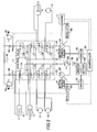
- Fig. 2 is a block diagram for illustrating a main part of a hydraulic system configuration according to a first embodiment.
- elements which may be the same as corresponding elements illustrated in Fig. 1 are given the same reference numerals.
- connections related to mechanical power are indicated by double lines
- hydraulic lines are indicated by solid lines
- electrical connections are indicated by bold line
- connections related to control are indicated by dashed lines.
- the turning motor 21 i.e., the electric motor as illustrated in Fig. 1
- the turning motor (a hydraulic motor) 19 which is hydraulically driven with the oil pressure generated by the first hydraulic pump 28 is used.
- the control valve 17 includes plural switching valves 171 through 178.
- the switching valves 171 through 174 are provided in a first oil line 42 connecting the discharge side of the first hydraulic pump 28 and a reservoir tank 40, and the switching valves 175 through 178 are provided in a second oil line 44 connecting the discharge side of the second hydraulic pump 14 and the reservoir tank 40.
- the switching valve 171 switches supply status of the working fluid for implementing a traveling operation of the travel left motor 1B
- the switching valve 172 switches supply status of the working fluid for implementing a turning operation of the turning motor 21
- the switching valve 173 switches supply status of the working fluid for implementing a boom-up operation (second speed) of the boom cylinder 7
- the switching valve 174 switches supply status of the working fluid for implementing an arm opening/closing operation (first speed) of the arm cylinder 8.
- the switching valve 175 switches supply status of the working fluid for implementing a traveling operation of the travel right motor 1A
- the switching valve 176 switches supply status of the working fluid for implementing a bucket opening/closing operation of the bucket cylinder 9
- the switching valve 177 switches supply status of the working fluid for implementing a boom-up/down operation (first speed) of the boom cylinder 7
- the switching valve 178 switches supply status of the working fluid for implementing an arm-opening/closing operation (second speed) of the arm cylinder 8.
- a negative control restrictor 46 (a restrictor for negative feedback) is provided between a downstream side of the switching valve 174 and the reservoir tank 40, and a negative control pressure Pn1 (a pressure at a upstream side of the negative control restrictor 46 is output to a regulator 54 for the negative feedback.
- the first oil line 42 is connected to a variable pressure relief valve 50 for adjusting a relief pressure of the first oil line 42.
- the controller 30 and the regulator 54 control the first hydraulic pump 28 based on the negative control pressure Pn1 such that a loss of rate of discharge of the first hydraulic pump 28 returning to the reservoir tank 40 is reduced (i.e., performs so-called negative control).
- a negative control restrictor 48 (a restrictor for negative feedback) is provided between a downstream side of the switching valve 178 and the reservoir tank 40, and a negative control pressure Pn2 (a pressure at a upstream side of the negative control restrictor 48 is output to a regulator 56 for the negative feedback.
- the second oil line 44 is connected to a variable pressure relief valve 52 for adjusting a relief pressure of the second oil line 44.
- the controller 30 and the regulator 56 control the second hydraulic pump 14 based on the negative control pressure Pn2 such that a loss of rate of discharge of the second hydraulic pump 14 returning to the reservoir tank 40 is reduced (i.e., performs so-called negative control). In this way, the first hydraulic pump 28 and the second hydraulic pump 14 are mechanically separated.
- first oil line 42 and the second oil line 44 are connected to a relief valve 60 for limiting the maximum pressure of the hydraulic circuit.
- the relief valve 60 is activated to connect the hydraulic circuit to a reservoir tank 62.
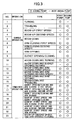
- Fig. 3 is a table for illustrating a relationship between various operations of the hybrid-type construction machine 100 according to the first embodiment and hydraulic pumps used for the operations.
- first hydraulic pump 28 and the second hydraulic pump 14 are arranged such that the first pump 28 controls at least one of the actuators 1A, 1B, 7, 8, 9 and 21 independently from the second pump 14 and the second pump 14 controls at least another one of the actuators 1A, 1B, 7, 8, 9 and 21 independently from the first pump 28.
- the first hydraulic pump 28 is arranged to control the travel left motor 1B and the turning motor 21 independently from the second hydraulic pump 14, and the second hydraulic pump 14 is arranged to control the travel right motor 1A and the bucket cylinder 9 independently from the first hydraulic pump 28.
- the first hydraulic pump 28 may be in fluid communication with the travel right motor 1A via a switching valve (not illustrated) and the second hydraulic pump 14 may in fluid communication with the travel left motor 1B via a switching valve (not illustrated).
- the second hydraulic pump 14 is only a hydraulic pump for driving an actuator(s) that is coupled to the engine 11 and the motor generator 12. In other word, only the second hydraulic pump 14 is coupled to the engine 11 and the motor generator 12 as a hydraulic pump for driving an actuator(s).
- the motor generator 27 does not necessarily have a generator function, it may be implemented by an electric motor.
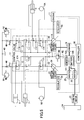
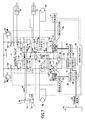
- Fig. 5 is a block diagram for illustrating a main part of a hydraulic system configuration according to a second embodiment.
- elements which may be the same as corresponding elements illustrated in Fig. 1 are given the same reference numerals.
- connections related to mechanical power are indicated by double lines
- hydraulic lines are indicated by solid lines
- electrical connections are indicated by bold line
- connections related to control are indicated by dashed lines.
- the turning motor 21 i.e., the electric motor which is electrically driven by the battery unit 19 and the inverter 20 is used.
- the battery unit 19 is electrically connected to the turning motor 21 via the inverter 20.
- An output shaft of the turning motor 21 is coupled to a turning mechanism 24 for turning an upper-part turning body of the hybrid-type construction machine 100.
- the turning mechanism 24 is driven with electric power from the battery unit 19.
- the inverter 20 is controlled based on operations of a turning operation lever by the controller 30.
- the turning motor 21 is a motor generator which can perform power running and regeneration and is PWM (Pulse Width Modulation) driven by the inverter 20.
- the turning motor 21 is an IMP motor in which magnets are buried inside a rotor.
- a torque of a rotational driving force of the turning motor 21 is amplified by the turning reduction gear 24, and the upper-part turning body 3 of the hybrid-type construction machine 100 is controlled to accelerate or decelerate its rotating motion.
- the number of revolutions is increased by the turning reduction gear 24 to be transmitted to the turning motor 21, and thus regenerative electric power can be generated.
- the control valve 17 includes plural switching valves 171 through 178. However, because of motorization of the turning motor 21, the switching valve 172 for the turning motor 21, which is used in the first embodiment, is omitted.
- the switching valves 171 through 174 are provided in a first oil line 42 connecting the discharge side of the first hydraulic pump 28 and a reservoir tank 40, and the switching valves 175 through 178 are provided in a second oil line 44 connecting the discharge side of the second hydraulic pump 14 and the reservoir tank 40.
- the switching valve 171 switches supply status of the working fluid for implementing a traveling operation of the travel left motor 1B
- the switching valve 173 switches supply status of the working fluid for implementing a boom-up operation (second speed) of the boom cylinder 7
- the switching valve 174 switches supply status of the working fluid for implementing an arm opening/closing operation (first speed) of the arm cylinder 8.
- the switching valve 175 switches supply status of the working fluid for implementing a traveling operation of the travel right motor 1A
- the switching valve 176 switches supply status of the working fluid for implementing a bucket opening/closing operation of the bucket cylinder 9
- the switching valve 177 switches supply status of the working fluid for implementing a boom-up/down operation (first speed) of the boom cylinder 7
- the switching valve 178 switches supply status of the working fluid for implementing an arm-opening/closing operation (second speed) of the arm cylinder 8.
- a negative control restrictor 46 (a restrictor for negative feedback) is provided between a downstream side of the switching valve 174 and the reservoir tank 40, and a negative control pressure Pn1 (a pressure at a upstream side of the negative control restrictor 46 is output to a regulator 54 for the negative feedback.
- the first oil line 42 is connected to a variable pressure relief valve 50 for adjusting a relief pressure of the first oil line 42.
- the controller 30 and the regulator 54 control the first hydraulic pump 28 based on the negative control pressure Pn1 such that a loss of rate of discharge of the first hydraulic pump 28 returning to the reservoir tank 40 is reduced.
- a negative control restrictor 48 (a restrictor for negative feedback) is provided between a downstream side of the switching valve 178 and the reservoir tank 40, and a negative control pressure Pn2 (a pressure at a upstream side of the negative control restrictor 48 is output to a regulator 56 for the negative feedback.
- the second oil line 44 is connected to a variable pressure relief valve 52 for adjusting a relief pressure of the second oil line 44.
- the controller 30 and the regulator 56 control the second hydraulic pump 14 based on the negative control pressure Pn2 such that a loss of rate of discharge of the second hydraulic pump 14 returning to the reservoir tank 40 is reduced (i.e., performs so-called negative control). In this way, the first hydraulic pump 28 and the second hydraulic pump 14 are mechanically separated.
- first oil line 42 and the second oil line 44 are connected to a relief valve 60 for limiting the maximum pressure of the hydraulic circuit.
- the relief valve 60 is activated to connect the hydraulic circuit to the reservoir tank 62.
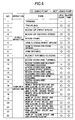
- Fig. 6 is a table for illustrating a relationship between various operations of the hybrid-type construction machine 100 according to the second embodiment and hydraulic pumps used for the operations.
- the first hydraulic pump 28 and the second hydraulic pump 14 are not operated.
- the turning operation alone is implemented by the turning motor 21 which is driven with electric power from the battery unit 19.
- the boom-up operation (first speed) alone only the second hydraulic pump 14 is used, and thus the first hydraulic pump 28 is not operated.
- the boom-down operation alone only the second hydraulic pump 14 is used, and thus the first hydraulic pump 28 is not operated.
- the bucket opening/closing operation alone only the second hydraulic pump 14 is used, and thus the first hydraulic pump 28 is not operated.
- first hydraulic pump 28 and the second hydraulic pump 14 are arranged such that the first pump 28 controls at least one of the actuators 1A, 1B, 7, 8 and 9 independently from the second pump 14 and the second pump 14 controls at least another one of the actuators 1A, 1B, 7, 8 and 9 independently from the first pump 28.
- the first hydraulic pump 28 is arranged to control the travel left motor 1B independently from the second hydraulic pump 14
- the second hydraulic pump 14 is arranged to control the travel right motor 1A and the bucket cylinder 9 independently from the first hydraulic pump 28.
- the first hydraulic pump 28 may be in fluid communication with the travel right motor 1A via a switching valve (not illustrated) and the second hydraulic pump 14 may in fluid communication with the travel left motor 1B via a switching valve (not illustrated).
- a hydraulic pump for driving an actuator(s) that is coupled to the engine 11 and the motor generator 12 includes the second hydraulic pump 14 only.
- the second hydraulic pump 14 is coupled to the engine 11 and the motor generator 12 as a hydraulic pump for driving an actuator(s).
- the hydraulic pump since only one of the hydraulic pump, which is used for driving an actuator(s), is coupled to the engine 11 and the motor generator 12, it is possible to reduce pumping loss at the time of idling by more than one-half with respect to the configuration in which two hydraulic pumps, which are used for driving actuators, are coupled to the engine 11 and the motor generator 12. Further, in order to compensate for the fact that only one hydraulic pump, which is used for driving an actuator(s), is coupled to the engine 11 and the motor generator 12, a hydraulic pump (the first hydraulic pump 28) for driving an actuator(s) is provided, which hydraulic pump is driven by the motor generator 27 (separate from the motor generator 12) using electric power from the battery unit 19.
- the turning operation is performed frequently depending on working circumstances. For this reason, at the time of performing the turning operation only, it is possible not to operate the first hydraulic pump 28. Further, it is also possible to stop even a rotating operation of the first hydraulic pump 28. Thus, since it is not necessary to pump the working fluid, it is possible to reduce the energy loss.
- the turning operation is often combined with the boom operation. Even in this case, the working fluid can be supplied to the boom from the second hydraulic pump 14 which is coupled to the engine 11, and thus the rotating operation of the first hydraulic pump 28 can be stopped. Thus, since it is not necessary to pump the working fluid even at the time of the combined operations, it is possible to reduce the energy loss.
- the motor generator 27 does not necessarily have a generator function, it may be implemented by an electric motor.
- Fig. 7 is a block diagram for illustrating a main part of a hydraulic system configuration according to a third embodiment.
- elements which may be the same as corresponding elements illustrated in Fig. 1 are given the same reference numerals.
- connections related to mechanical power are indicated by double lines
- hydraulic lines are indicated by solid lines
- electrical connections are indicated by bold line
- connections related to control are indicated by dashed lines.
- the turning motor 21 i.e., the electric motor which is electrically driven by the battery unit 19 and the inverter 20 is used.
- the control valve 17 includes plural switching valves 171 through 178. However, because of motorization of the turning motor 21, the switching valve 172 for the turning motor 21, which is used in the first embodiment, is omitted.
- the switching valves 171 through 174 are provided in a first oil line 42 connecting the discharge side of the first hydraulic pump 28 and a reservoir tank 40, and the switching valves 175 through 178 are provided in a second oil line 44 connecting the discharge side of the second hydraulic pump 14 and the reservoir tank 40.
- the switching valve 171 switches supply status of the working fluid for implementing a traveling operation of the travel left motor 1B
- the switching valve 173 switches supply status of the working fluid for implementing a boom-up operation (second speed) of the boom cylinder 7
- the switching valve 174 switches supply status of the working fluid for implementing an arm opening/closing operation (second speed) of the arm cylinder 8.
- the switching valve 175 switches supply status of the working fluid for implementing a traveling operation of the travel right motor 1A
- the switching valve 176 switches supply status of the working fluid for implementing a bucket opening/closing operation of the bucket cylinder 9
- the switching valve 177 switches supply status of the working fluid for implementing a boom-up/down operation (first speed) of the boom cylinder 7
- the switching valve 178 switches supply status of the working fluid for implementing an arm-opening/closing operation (first speed) of the arm cylinder 8.
- a negative control restrictor 46 (a restrictor for negative feedback) is provided between a downstream side of the switching valve 174 and the reservoir tank 40, and a negative control pressure Pn1 (a pressure at a upstream side of the negative control restrictor 46 is output to a regulator 54 for the negative feedback.
- the first oil line 42 is connected to a variable pressure relief valve 50 for adjusting a relief pressure of the first oil line 42.
- the controller 30 and the regulator 54 control the first hydraulic pump 28 based on the negative control pressure Pn1 such that a loss of rate of discharge of the first hydraulic pump 28 returning to the reservoir tank 40 is reduced.
- a negative control restrictor 48 (a restrictor for negative feedback) is provided between a downstream side of the switching valve 178 and the reservoir tank 40, and a negative control pressure Pn2 (a pressure at a upstream side of the negative control restrictor 48 is output to a regulator 56 for the negative feedback.
- the second oil line 44 is connected to a variable pressure relief valve 52 for adjusting a relief pressure of the second oil line 44.
- the controller 30 and the regulator 56 control the second hydraulic pump 14 based on the negative control pressure Pn2 such that a loss of rate of discharge of the second hydraulic pump 14 returning to the reservoir tank 40 is reduced (i.e., performs so-called negative control). In this way, the first hydraulic pump 28 and the second hydraulic pump 14 are mechanically separated.
- first oil line 42 and the second oil line 44 are connected to a relief valve 60 for limiting the maximum pressure of the hydraulic circuit.
- the relief valve 60 is activated to connect the hydraulic circuit to the reservoir tank 62.
- the first hydraulic pump 28 is of a pump motor type which is capable of regenerating the energy in concert with the motor generator 27. Specifically, at the time of functioning as a motor, the first hydraulic pump 28 is rotated by the returning oil which has flowed from the head chamber of the boom cylinder 7 to be discharged to the tank 62. This rotation causes the motor generator 27 to rotate, thereby performing a regenerative operation.
- a regenerative circuit 64 is provided between the switching valve 177 for the first speed operation of the boom cylinder 7 and the first hydraulic pump 28. The regenerative circuit 64 establishes fluid communication between the head chamber 7a of the boom cylinder 7 and the first hydraulic pump 28 according to the position of the switching valve 177.
- a flow control valve 66 which is controlled by the controller 30, and a check valve 68 are provided in the regenerative circuit 64.
- a port 28a of the first hydraulic pump 28 is a port for discharge and inflow.
- the first hydraulic pump 28 maintains the same rotating direction in the case of functioning as a pump for pumping the working fluid from the tank 62 to the respective actuators and in the case of functioning as a motor for having the returning oil flowing therein from the head chamber 7a of the boom cylinder 7 to discharge it to the tank 62.
- the discharging direction changes, it is possible to smoothly switch the function between the pump and the motor.
- Fig. 7 the flow of the working fluid in the hydraulic circuit including the regenerative circuit 64 at the time of the boom down operation is shown by arrows r1 through r12.
- the working fluid discharged from the first hydraulic pump 28 is supplied to the rod chamber 7b of the boom cylinder 7 via the switching valve 177 as indicated by the arrows r1 through r6.
- the working fluid discharged from the head chamber 7a is supplied to the first hydraulic pump 28 via the switching valve 177 and through the regenerative circuit 64 as indicated by the arrows r7 through r12.
- the first hydraulic pump 28 causes the motor generator 27 to perform the regenerative operation.
- regenerative energy (electric energy) obtained at that time is used to charge the battery 19B of the battery unit 19 via the inverter 25.
- the energy may be supplied to the turning motor 21 via the inverter 20 or may be supplied to the motor generator 12 via the inverter 18.
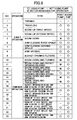
- Fig. 8 is a table for illustrating a relationship between various operations of the hybrid-type construction machine 100 according to the third embodiment and hydraulic pumps used for the operations.
- the first hydraulic pump 28 and the second hydraulic pump 14 are not operated.
- the turning operation alone is implemented by the turning motor 21 which is driven with electric power from the battery unit 19.
- the boom-up operation (first speed) alone only the second hydraulic pump 14 is used, and thus the first hydraulic pump 28 is not operated.
- the boom-down operation alone only the second hydraulic pump 14 is used, and the first hydraulic pump 28 performs the regenerative operation.
- the bucket opening/closing operation alone only the second hydraulic pump 14 is used, and thus the first hydraulic pump 28 is not operated.
- first hydraulic pump 28 and the second hydraulic pump 14 are arranged such that the first pump 28 controls at least one of the actuators 1A, 1B, 7, 8 and 9 independently from the second pump 14 and the second pump 14 controls at least another one of the actuators 1A, 1B, 7, 8 and 9 independently from the first pump 28.
- the first hydraulic pump 28 is arranged to control the travel left motor 1B independently from the second hydraulic pump 14
- the second hydraulic pump 14 is arranged to control the travel right motor 1A and the bucket cylinder 9 independently from the first hydraulic pump 28.
- the first hydraulic pump 28 may be in fluid communication with the travel right motor 1A via a switching valve (not illustrated) and the second hydraulic pump 14 may in fluid communication with the travel left motor 1B via a switching valve (not illustrated).
- a hydraulic pump for driving an actuator(s) that is coupled to the engine 11 and the motor generator 12 includes the second hydraulic pump 14 only.
- only the second hydraulic pump 14 is coupled to the engine 11 and the motor generator 12 as a hydraulic pump for driving an actuator(s).
- the first hydraulic pump 28 is of a pump motor type and the regenerative circuit 64 is provided between the first hydraulic pump 28 and the boom cylinder 7.
- the regenerative energy can be obtained by the first hydraulic pump 28 and the motor generator 27 at the time of the operations involving the boom-down operation (see No. 5, 10, 11, 12, 14 and 15 in Fig. 8 ).
- one of feature configurations of the third embodiment is that the switching valve 178 for the arm opening/closing operation (first speed) of the arm cylinder 8 is provided in the second oil line 44 on the side of the second hydraulic pump 14, and the switching valve 174 for the arm opening/closing operation (second speed) of the arm cylinder 8 is provided in the first oil line 42 on the side of the first hydraulic pump 28.
- the number of operations i.e., the number of operation types
- the switching valve 178 for the arm opening/closing operation (first speed) of the arm cylinder 8 may be provided in the first oil line 42 on the side of the first hydraulic pump 28, and the switching valve 174 for the arm opening/closing operation (second speed) of the arm cylinder 8 may be provided in the second oil line 44 on the side of the second hydraulic pump 14. In this case, it is possible to obtain the effects of the second embodiment and improve the energy saving by the regenerative operation.
Landscapes
- Engineering & Computer Science (AREA)
- Mining & Mineral Resources (AREA)
- Civil Engineering (AREA)
- General Engineering & Computer Science (AREA)
- Structural Engineering (AREA)
- Physics & Mathematics (AREA)
- Fluid Mechanics (AREA)
- Mechanical Engineering (AREA)
- Chemical & Material Sciences (AREA)
- Combustion & Propulsion (AREA)
- Transportation (AREA)
- Fluid-Pressure Circuits (AREA)
- Operation Control Of Excavators (AREA)
Applications Claiming Priority (2)
| Application Number | Priority Date | Filing Date | Title |
|---|---|---|---|
| JP2009213642 | 2009-09-15 | ||
| PCT/JP2010/065854 WO2011034061A1 (fr) | 2009-09-15 | 2010-09-14 | Machine de construction hybride |
Publications (2)
| Publication Number | Publication Date |
|---|---|
| EP2479351A1 true EP2479351A1 (fr) | 2012-07-25 |
| EP2479351A4 EP2479351A4 (fr) | 2017-07-05 |
Family
ID=43758664
Family Applications (1)
| Application Number | Title | Priority Date | Filing Date |
|---|---|---|---|
| EP10817174.5A Withdrawn EP2479351A4 (fr) | 2009-09-15 | 2010-09-14 | Machine de construction hybride |
Country Status (6)
| Country | Link |
|---|---|
| US (1) | US9151019B2 (fr) |
| EP (1) | EP2479351A4 (fr) |
| JP (1) | JP5657548B2 (fr) |
| KR (1) | KR101378249B1 (fr) |
| CN (1) | CN102549219B (fr) |
| WO (1) | WO2011034061A1 (fr) |
Cited By (7)
| Publication number | Priority date | Publication date | Assignee | Title |
|---|---|---|---|---|
| EP2711469A1 (fr) * | 2012-09-25 | 2014-03-26 | Wacker Neuson AG | Engin avec entraînement hybride |
| EP3620581A1 (fr) * | 2018-09-10 | 2020-03-11 | Artemis Intelligent Power Limited | Appareil comportant un circuit hydraulique |
| WO2020053577A1 (fr) * | 2018-09-10 | 2020-03-19 | Artemis Intelligent Power Limited | Appareil pourvu d'un dispositif de commande de machine hydraulique |
| EP3546662A4 (fr) * | 2016-11-24 | 2020-08-26 | Hitachi Construction Machinery Co., Ltd. | Machine de construction |
| US10995476B2 (en) | 2018-09-10 | 2021-05-04 | Artemis Intelligent Power Limited | Apparatus |
| US11261862B2 (en) | 2018-09-10 | 2022-03-01 | Artemis Intelligent Power Limited | Hydrostatic apparatus and method of operating the same |
| EP4215675A1 (fr) * | 2022-01-21 | 2023-07-26 | BAUER Maschinen GmbH | Machine de construction hybride et procédé de fonctionnement d'une machine de construction hybride |
Families Citing this family (24)
| Publication number | Priority date | Publication date | Assignee | Title |
|---|---|---|---|---|
| CN102483433B (zh) * | 2009-09-15 | 2014-09-24 | 住友重机械工业株式会社 | 混合式施工机械中的控制方法及控制装置 |
| WO2013035815A1 (fr) * | 2011-09-09 | 2013-03-14 | 住友重機械工業株式会社 | Pelle, et procédé de commande de celle-ci |
| KR101991983B1 (ko) * | 2011-12-28 | 2019-06-21 | 히다찌 겐끼 가부시키가이샤 | 작업 기계의 동력 회생 장치 및 작업 기계 |
| WO2013118308A1 (fr) * | 2012-02-06 | 2013-08-15 | Mitsui Engineering & Shipbuilding Co.,Ltd. | Dispositif de récupération d'énergie excédentaire de turbocompresseur pour moteur à combustion interne |
| JP5767996B2 (ja) * | 2012-03-29 | 2015-08-26 | カヤバ工業株式会社 | 流体圧駆動ユニット |
| JP5934543B2 (ja) * | 2012-03-29 | 2016-06-15 | Kyb株式会社 | 流体圧駆動ユニット |
| US9725880B2 (en) * | 2012-06-08 | 2017-08-08 | Volvo Construction Equipment Ab | Apparatus for controlling a cascaded hybrid construction machine system and a method therefor |
| WO2014054983A1 (fr) * | 2012-10-03 | 2014-04-10 | Volvo Construction Equipment Ab | Agencement de levage pour un engin de travail |
| DE102012111296A1 (de) * | 2012-11-22 | 2014-05-22 | Linde Hydraulics Gmbh & Co. Kg | Antriebsstrang eines Fahrzeugs, insbesondere einer mobilen Arbeitsmaschine |
| US9441347B2 (en) | 2013-08-05 | 2016-09-13 | Deere & Company | Methods and apparatus to control a dual function work machine |
| EP3358202A4 (fr) * | 2015-09-28 | 2018-10-10 | Bosch Rexroth Corporation | Dispositif d'entraînement à vérin hydraulique |
| KR101779860B1 (ko) | 2015-10-28 | 2017-09-19 | 가부시키가이샤 고마쓰 세이사쿠쇼 | 건설 기계의 구동 장치 |
| JP2017180045A (ja) * | 2016-03-31 | 2017-10-05 | 住友重機械工業株式会社 | ショベルのシリーズ、ショベルの油圧回路、及びショベル |
| KR101819929B1 (ko) * | 2016-04-28 | 2018-01-19 | 재단법인 건설기계부품연구원 | 건설장비 주행모터의 사판 제어장치 |
| CN106013312B (zh) * | 2016-06-12 | 2018-06-29 | 上海理工大学 | 全电驱动的液压挖掘机动力系统 |
| CN108026945B (zh) * | 2016-08-26 | 2020-01-07 | 株式会社小松制作所 | 控制系统、作业机械及控制方法 |
| CN106438525B (zh) * | 2016-10-20 | 2018-05-01 | 燕山大学 | 一种功率回收型液压恒压装置 |
| DE102016220964A1 (de) * | 2016-10-25 | 2018-04-26 | Schaeffler Technologies AG & Co. KG | Hydraulikkreislauf für einen Hybridantriebsstrang |
| DE102019123993A1 (de) * | 2019-09-06 | 2021-03-11 | Ffg Flensburger Fahrzeugbau Gesellschaft Mbh | Hydraulikanlage |
| US11946225B2 (en) * | 2021-05-28 | 2024-04-02 | Caterpillar Inc. | Method and systems for controlling electrically-powered hydraulic circuits |
| DE102022206509A1 (de) | 2022-06-28 | 2023-12-28 | Robert Bosch Gesellschaft mit beschränkter Haftung | Hydraulischer Antrieb und Verfahren zum regenerativen Absenken eines Elements einer Arbeitsmaschine |
| CN121712947A (zh) * | 2023-08-18 | 2026-03-20 | 山特维克矿山工程机械有限公司 | 冗余双泵液压系统及其加权操作的方法 |
| KR102777872B1 (ko) * | 2024-09-01 | 2025-03-12 | 주식회사 엘렉트 | 굴착기 전동화 모듈 및 이를 구비하는 굴착기 |
| WO2026049527A1 (fr) * | 2024-09-01 | 2026-03-05 | 주식회사 엘렉트 | Module d'électrification d'excavatrice et excavatrice le comprenant |
Family Cites Families (10)
| Publication number | Priority date | Publication date | Assignee | Title |
|---|---|---|---|---|
| DE60141137D1 (de) * | 2000-05-23 | 2010-03-11 | Kobelco Constr Machinery Ltd | Baumaschine |
| JP4480908B2 (ja) * | 2001-02-19 | 2010-06-16 | 住友建機株式会社 | ハイブリッドショベル |
| JP3969068B2 (ja) * | 2001-11-21 | 2007-08-29 | コベルコ建機株式会社 | ハイブリッド作業機械のアクチュエータ駆動装置 |
| JP2003214212A (ja) * | 2002-01-18 | 2003-07-30 | Sumitomo (Shi) Construction Machinery Manufacturing Co Ltd | 舗装機械のエンジン制御装置 |
| JP2004011168A (ja) * | 2002-06-04 | 2004-01-15 | Komatsu Ltd | 建設機械 |
| JP4509877B2 (ja) | 2005-06-29 | 2010-07-21 | キャタピラージャパン株式会社 | 作業機械のハイブリッドシステム |
| JP2007177437A (ja) * | 2005-12-27 | 2007-07-12 | Shin Caterpillar Mitsubishi Ltd | オープンループ式制御機械の力行・回生判別装置 |
| CN101321642A (zh) * | 2006-03-13 | 2008-12-10 | 博世力士乐股份有限公司 | 包括动力分置式传动装置的机械-液压驱动机构 |
| JP4524679B2 (ja) * | 2006-03-15 | 2010-08-18 | コベルコ建機株式会社 | ハイブリッド建設機械 |
| JP2009213642A (ja) | 2008-03-10 | 2009-09-24 | Aruze Corp | 遊技機 |
-
2010
- 2010-09-14 CN CN201080038829.0A patent/CN102549219B/zh active Active
- 2010-09-14 JP JP2011531932A patent/JP5657548B2/ja not_active Expired - Fee Related
- 2010-09-14 WO PCT/JP2010/065854 patent/WO2011034061A1/fr not_active Ceased
- 2010-09-14 US US13/395,690 patent/US9151019B2/en not_active Expired - Fee Related
- 2010-09-14 KR KR1020127006024A patent/KR101378249B1/ko not_active Expired - Fee Related
- 2010-09-14 EP EP10817174.5A patent/EP2479351A4/fr not_active Withdrawn
Non-Patent Citations (1)
| Title |
|---|
| See references of WO2011034061A1 * |
Cited By (11)
| Publication number | Priority date | Publication date | Assignee | Title |
|---|---|---|---|---|
| EP2711469A1 (fr) * | 2012-09-25 | 2014-03-26 | Wacker Neuson AG | Engin avec entraînement hybride |
| EP3546662A4 (fr) * | 2016-11-24 | 2020-08-26 | Hitachi Construction Machinery Co., Ltd. | Machine de construction |
| EP3620581A1 (fr) * | 2018-09-10 | 2020-03-11 | Artemis Intelligent Power Limited | Appareil comportant un circuit hydraulique |
| WO2020053577A1 (fr) * | 2018-09-10 | 2020-03-19 | Artemis Intelligent Power Limited | Appareil pourvu d'un dispositif de commande de machine hydraulique |
| CN112673136A (zh) * | 2018-09-10 | 2021-04-16 | 阿尔特弥斯智能动力有限公司 | 带有液压机控制器的设备 |
| US10995476B2 (en) | 2018-09-10 | 2021-05-04 | Artemis Intelligent Power Limited | Apparatus |
| US11261862B2 (en) | 2018-09-10 | 2022-03-01 | Artemis Intelligent Power Limited | Hydrostatic apparatus and method of operating the same |
| US11454003B2 (en) | 2018-09-10 | 2022-09-27 | Artemis Intelligent Power Limited | Apparatus with hydraulic machine controller |
| US11555293B2 (en) | 2018-09-10 | 2023-01-17 | Artemis Intelligent Power Limited | Apparatus with hydraulic machine controller |
| CN112673136B (zh) * | 2018-09-10 | 2023-06-09 | 阿尔特弥斯智能动力有限公司 | 带有液压机控制器的设备 |
| EP4215675A1 (fr) * | 2022-01-21 | 2023-07-26 | BAUER Maschinen GmbH | Machine de construction hybride et procédé de fonctionnement d'une machine de construction hybride |
Also Published As
| Publication number | Publication date |
|---|---|
| KR20120053031A (ko) | 2012-05-24 |
| WO2011034061A1 (fr) | 2011-03-24 |
| US20120167561A1 (en) | 2012-07-05 |
| KR101378249B1 (ko) | 2014-03-25 |
| CN102549219B (zh) | 2015-02-25 |
| JP5657548B2 (ja) | 2015-01-21 |
| CN102549219A (zh) | 2012-07-04 |
| US9151019B2 (en) | 2015-10-06 |
| JPWO2011034061A1 (ja) | 2013-02-14 |
| EP2479351A4 (fr) | 2017-07-05 |
Similar Documents
| Publication | Publication Date | Title |
|---|---|---|
| US9151019B2 (en) | Hybrid type construction machine | |
| JP3969068B2 (ja) | ハイブリッド作業機械のアクチュエータ駆動装置 | |
| EP1191155B1 (fr) | Excavatrice avec un dispositif de commande hybride | |
| KR100813727B1 (ko) | 건설기계 | |
| CN101663486B (zh) | 液压机构以及包括该液压机构的施工设备 | |
| JP5203434B2 (ja) | ハイブリッド建設機械 | |
| JP5665874B2 (ja) | ハイブリッド型作業機械及びその制御方法 | |
| WO2000058569A1 (fr) | Excavatrice | |
| JP2005194978A (ja) | 作業機械 | |
| JP2008280796A (ja) | パラレルハイブリッド駆動装置及びそれを備えた建設機械 | |
| JP2001329573A (ja) | 建設機械 | |
| CN108138468B (zh) | 施工机械 | |
| JP2008275100A (ja) | 建設車両 | |
| JP3875900B2 (ja) | 建設機械の動力装置 | |
| JP5208067B2 (ja) | ハイブリッド建設機械の制御装置 | |
| JP5442383B2 (ja) | ハイブリッド型建設機械 | |
| JP7285380B2 (ja) | 建設機械 | |
| JP5318329B2 (ja) | ハイブリッド型建設機械の駆動装置 | |
| JP4798149B2 (ja) | ハイブリッド型油圧装置 | |
| JP2016056864A (ja) | 作業機械の駆動システム | |
| JP5399105B2 (ja) | ハイブリッド式作業機械 | |
| JP5371210B2 (ja) | 油圧式建設機械 | |
| JP2002322682A (ja) | ショベル | |
| JP2015198495A (ja) | ショベル |
Legal Events
| Date | Code | Title | Description |
|---|---|---|---|
| PUAI | Public reference made under article 153(3) epc to a published international application that has entered the european phase |
Free format text: ORIGINAL CODE: 0009012 |
|
| 17P | Request for examination filed |
Effective date: 20120320 |
|
| AK | Designated contracting states |
Kind code of ref document: A1 Designated state(s): AL AT BE BG CH CY CZ DE DK EE ES FI FR GB GR HR HU IE IS IT LI LT LU LV MC MK MT NL NO PL PT RO SE SI SK SM TR |
|
| DAX | Request for extension of the european patent (deleted) | ||
| RA4 | Supplementary search report drawn up and despatched (corrected) |
Effective date: 20170602 |
|
| RIC1 | Information provided on ipc code assigned before grant |
Ipc: E02F 9/20 20060101AFI20170529BHEP Ipc: B60K 6/46 20071001ALI20170529BHEP Ipc: E02F 9/22 20060101ALI20170529BHEP |
|
| STAA | Information on the status of an ep patent application or granted ep patent |
Free format text: STATUS: EXAMINATION IS IN PROGRESS |
|
| 17Q | First examination report despatched |
Effective date: 20180712 |
|
| RIC1 | Information provided on ipc code assigned before grant |
Ipc: B60K 6/46 20071001ALI20170529BHEP Ipc: E02F 9/22 20060101ALI20170529BHEP Ipc: E02F 9/20 20060101AFI20170529BHEP |
|
| STAA | Information on the status of an ep patent application or granted ep patent |
Free format text: STATUS: THE APPLICATION IS DEEMED TO BE WITHDRAWN |
|
| 18D | Application deemed to be withdrawn |
Effective date: 20210401 |