EP2479438A2 - Système hydraulique doté d'au moins une machine d'entraînement - Google Patents
Système hydraulique doté d'au moins une machine d'entraînement Download PDFInfo
- Publication number
- EP2479438A2 EP2479438A2 EP12151440A EP12151440A EP2479438A2 EP 2479438 A2 EP2479438 A2 EP 2479438A2 EP 12151440 A EP12151440 A EP 12151440A EP 12151440 A EP12151440 A EP 12151440A EP 2479438 A2 EP2479438 A2 EP 2479438A2
- Authority
- EP
- European Patent Office
- Prior art keywords
- machine
- hydraulic
- hydraulic cylinder
- working
- piston
- Prior art date
- Legal status (The legal status is an assumption and is not a legal conclusion. Google has not performed a legal analysis and makes no representation as to the accuracy of the status listed.)
- Withdrawn
Links
- 239000012530 fluid Substances 0.000 claims abstract description 15
- 230000005484 gravity Effects 0.000 claims description 6
- 238000000034 method Methods 0.000 description 4
- 238000010586 diagram Methods 0.000 description 3
- 239000010720 hydraulic oil Substances 0.000 description 2
- 230000003247 decreasing effect Effects 0.000 description 1
- 238000006073 displacement reaction Methods 0.000 description 1
- 238000004146 energy storage Methods 0.000 description 1
- 238000005381 potential energy Methods 0.000 description 1
Images

Classifications
-
- F—MECHANICAL ENGINEERING; LIGHTING; HEATING; WEAPONS; BLASTING
- F15—FLUID-PRESSURE ACTUATORS; HYDRAULICS OR PNEUMATICS IN GENERAL
- F15B—SYSTEMS ACTING BY MEANS OF FLUIDS IN GENERAL; FLUID-PRESSURE ACTUATORS, e.g. SERVOMOTORS; DETAILS OF FLUID-PRESSURE SYSTEMS, NOT OTHERWISE PROVIDED FOR
- F15B11/00—Servomotor systems without provision for follow-up action; Circuits therefor
- F15B11/02—Systems essentially incorporating special features for controlling the speed or actuating force of an output member
- F15B11/024—Systems essentially incorporating special features for controlling the speed or actuating force of an output member by means of differential connection of the servomotor lines, e.g. regenerative circuits
-
- B—PERFORMING OPERATIONS; TRANSPORTING
- B66—HOISTING; LIFTING; HAULING
- B66F—HOISTING, LIFTING, HAULING OR PUSHING, NOT OTHERWISE PROVIDED FOR, e.g. DEVICES WHICH APPLY A LIFTING OR PUSHING FORCE DIRECTLY TO THE SURFACE OF A LOAD
- B66F11/00—Lifting devices specially adapted for particular uses not otherwise provided for
- B66F11/04—Lifting devices specially adapted for particular uses not otherwise provided for for movable platforms or cabins, e.g. on vehicles, permitting workmen to place themselves in any desired position for carrying out required operations
- B66F11/044—Working platforms suspended from booms
- B66F11/046—Working platforms suspended from booms of the telescoping type
-
- B—PERFORMING OPERATIONS; TRANSPORTING
- B66—HOISTING; LIFTING; HAULING
- B66F—HOISTING, LIFTING, HAULING OR PUSHING, NOT OTHERWISE PROVIDED FOR, e.g. DEVICES WHICH APPLY A LIFTING OR PUSHING FORCE DIRECTLY TO THE SURFACE OF A LOAD
- B66F9/00—Devices for lifting or lowering bulky or heavy goods for loading or unloading purposes
- B66F9/06—Devices for lifting or lowering bulky or heavy goods for loading or unloading purposes movable, with their loads, on wheels or the like, e.g. fork-lift trucks
- B66F9/075—Constructional features or details
- B66F9/20—Means for actuating or controlling masts, platforms, or forks
- B66F9/22—Hydraulic devices or systems
-
- F—MECHANICAL ENGINEERING; LIGHTING; HEATING; WEAPONS; BLASTING
- F15—FLUID-PRESSURE ACTUATORS; HYDRAULICS OR PNEUMATICS IN GENERAL
- F15B—SYSTEMS ACTING BY MEANS OF FLUIDS IN GENERAL; FLUID-PRESSURE ACTUATORS, e.g. SERVOMOTORS; DETAILS OF FLUID-PRESSURE SYSTEMS, NOT OTHERWISE PROVIDED FOR
- F15B2211/00—Circuits for servomotor systems
- F15B2211/30—Directional control
- F15B2211/305—Directional control characterised by the type of valves
- F15B2211/30505—Non-return valves, i.e. check valves
-
- F—MECHANICAL ENGINEERING; LIGHTING; HEATING; WEAPONS; BLASTING
- F15—FLUID-PRESSURE ACTUATORS; HYDRAULICS OR PNEUMATICS IN GENERAL
- F15B—SYSTEMS ACTING BY MEANS OF FLUIDS IN GENERAL; FLUID-PRESSURE ACTUATORS, e.g. SERVOMOTORS; DETAILS OF FLUID-PRESSURE SYSTEMS, NOT OTHERWISE PROVIDED FOR
- F15B2211/00—Circuits for servomotor systems
- F15B2211/30—Directional control
- F15B2211/305—Directional control characterised by the type of valves
- F15B2211/3056—Assemblies of multiple valves
- F15B2211/3059—Assemblies of multiple valves having multiple valves for multiple output members
-
- F—MECHANICAL ENGINEERING; LIGHTING; HEATING; WEAPONS; BLASTING
- F15—FLUID-PRESSURE ACTUATORS; HYDRAULICS OR PNEUMATICS IN GENERAL
- F15B—SYSTEMS ACTING BY MEANS OF FLUIDS IN GENERAL; FLUID-PRESSURE ACTUATORS, e.g. SERVOMOTORS; DETAILS OF FLUID-PRESSURE SYSTEMS, NOT OTHERWISE PROVIDED FOR
- F15B2211/00—Circuits for servomotor systems
- F15B2211/30—Directional control
- F15B2211/31—Directional control characterised by the positions of the valve element
- F15B2211/3122—Special positions other than the pump port being connected to working ports or the working ports being connected to the return line
- F15B2211/3127—Floating position connecting the working ports and the return line
-
- F—MECHANICAL ENGINEERING; LIGHTING; HEATING; WEAPONS; BLASTING
- F15—FLUID-PRESSURE ACTUATORS; HYDRAULICS OR PNEUMATICS IN GENERAL
- F15B—SYSTEMS ACTING BY MEANS OF FLUIDS IN GENERAL; FLUID-PRESSURE ACTUATORS, e.g. SERVOMOTORS; DETAILS OF FLUID-PRESSURE SYSTEMS, NOT OTHERWISE PROVIDED FOR
- F15B2211/00—Circuits for servomotor systems
- F15B2211/30—Directional control
- F15B2211/315—Directional control characterised by the connections of the valve or valves in the circuit
- F15B2211/31523—Directional control characterised by the connections of the valve or valves in the circuit being connected to a pressure source and an output member
- F15B2211/31541—Directional control characterised by the connections of the valve or valves in the circuit being connected to a pressure source and an output member having a single pressure source and multiple output members
-
- F—MECHANICAL ENGINEERING; LIGHTING; HEATING; WEAPONS; BLASTING
- F15—FLUID-PRESSURE ACTUATORS; HYDRAULICS OR PNEUMATICS IN GENERAL
- F15B—SYSTEMS ACTING BY MEANS OF FLUIDS IN GENERAL; FLUID-PRESSURE ACTUATORS, e.g. SERVOMOTORS; DETAILS OF FLUID-PRESSURE SYSTEMS, NOT OTHERWISE PROVIDED FOR
- F15B2211/00—Circuits for servomotor systems
- F15B2211/70—Output members, e.g. hydraulic motors or cylinders or control therefor
- F15B2211/705—Output members, e.g. hydraulic motors or cylinders or control therefor characterised by the type of output members or actuators
- F15B2211/7051—Linear output members
- F15B2211/7053—Double-acting output members
-
- F—MECHANICAL ENGINEERING; LIGHTING; HEATING; WEAPONS; BLASTING
- F15—FLUID-PRESSURE ACTUATORS; HYDRAULICS OR PNEUMATICS IN GENERAL
- F15B—SYSTEMS ACTING BY MEANS OF FLUIDS IN GENERAL; FLUID-PRESSURE ACTUATORS, e.g. SERVOMOTORS; DETAILS OF FLUID-PRESSURE SYSTEMS, NOT OTHERWISE PROVIDED FOR
- F15B2211/00—Circuits for servomotor systems
- F15B2211/70—Output members, e.g. hydraulic motors or cylinders or control therefor
- F15B2211/71—Multiple output members, e.g. multiple hydraulic motors or cylinders
-
- F—MECHANICAL ENGINEERING; LIGHTING; HEATING; WEAPONS; BLASTING
- F15—FLUID-PRESSURE ACTUATORS; HYDRAULICS OR PNEUMATICS IN GENERAL
- F15B—SYSTEMS ACTING BY MEANS OF FLUIDS IN GENERAL; FLUID-PRESSURE ACTUATORS, e.g. SERVOMOTORS; DETAILS OF FLUID-PRESSURE SYSTEMS, NOT OTHERWISE PROVIDED FOR
- F15B2211/00—Circuits for servomotor systems
- F15B2211/80—Other types of control related to particular problems or conditions
- F15B2211/88—Control measures for saving energy
Definitions
- the invention relates to a hydraulic system with at least one drive machine, in particular a pump, and with at least two work machines, in particular two designed as hydraulic cylinders work machines, each machine via two, depending on the operating state of the machine as inlet or return serving connections by means of corresponding pressure lines with the each associated drive machine is connected, and at least one associated with each work machine valve for adjusting the operating state of the respective work machine.
- Such hydraulic systems are used for example in aerial work platforms.
- hydraulic resistance controls are used for lifting and lowering of loads.
- the volume flow of hydraulic fluid delivered by the drive machine, in particular the pump is conducted via valves (resistors) to the working machines, for example to the hydraulic cylinders.
- the system pressure adjusts depending on the loads on the working machines.
- the speed of a work machine is adjusted via the valve assigned to this work machine. The further the valve is opened, the higher the volume flow to this work machine and the faster, for example, a cylinder drives an aerial work platform on or off.
- the system pressure is lower when retracting the work machine than during extension, since the load supports retraction, especially in a vertical retraction, due to gravity.
- the effluent hydraulic oil is returned via the corresponding valve in the tank. This energy loss can occur.
- no more energy can be introduced into the system.
- working machines under load such as hydraulic cylinders, can only be retracted but not extended.
- the object of the invention is to avoid the aforementioned disadvantages and to provide a hydraulic system in which the energy during retraction, for example in an aerial work platform, can be used.
- connection which is at an operating state of this machine, which is effected by gravity or at least supported, serves as a flow, bypassing the engine via a bypass directly with the at a desired operating state as Connected to serving port of another work machine, so that the effluent from the first work machine hydraulic fluid flows to actuate the other work machine.
- the hydraulic system according to the invention is explained below using the example of an aerial work platform.
- aerial work platforms is provided as a prime mover a pump which is driven by a suitable motor.
- a working machine hydraulic cylinders are provided.
- a tank is provided with the pump connected to the tank. But it is also quite possible that the recirculated hydraulic fluid is directly made available to the pump again.
- Aerial work platforms have a boom system consisting of several outriggers. Especially with larger aerial work platforms, a boom consists of several sub-elements, which are telescopically telescoped by a suitable hydraulic cylinder.
- the relevant hydraulic cylinder is extended.
- the hydraulic fluid in the lower cavity of this hydraulic cylinder is pressed into the bypass by gravity and can be used by the inventive design for operating another hydraulic cylinder. In this way, for example, the hydraulic cylinder can be extended to change the orientation of the basket.
- the pump can assist in this process. It is of course also possible that the pump is completely switched off in this process.
- a bypass is understood as meaning solutions which bypass the drive machine. It is also quite possible that the bypass is formed only by a bypass line to the pump and behind the pump, a check valve is provided so that when the check valve is closed, the hydraulic fluid through the bypass, bypassing the pump to be led. Of course it is also possible that the pump is only switched off.
- a valve may be provided. This may be a flow control valve, so that the amount to be flowed can be adjusted. It is of course also possible that the valve is displaceable only between an on and off position.
- a work machine may be formed as a closed hydraulic cylinder with a displaceably arranged in the hydraulic cylinder piston, the piston separates the hydraulic cylinder into two cavities and on the piston a piston rod is mounted, which is performed by a correspondingly formed opening in a cylinder end face, each cavity each associated with a leading into this cavity port.
- an intermediate wall is provided to form a subspace with the adjacent Zylinderend constitutional, wherein the subspace is connected via at least one opening in the intermediate wall with the respective cavity and the bypass opens into the subspace.
- the opening is arranged in the middle of the intermediate wall. It also makes sense if the intermediate wall is arranged at a small distance from the cylinder end surface.
- Fig. 2 is an aerial work platform with a boom system consisting of a main boom 1, from a secondary boom 2 and from an end-mounted on the side arm 2 basket 3 shown.
- the main boom 1 and the secondary boom 2 each consist of five or three boom sub-elements, which are telescopically telescoped.
- a hydraulic cylinder 4 is provided for aligning the main boom 1 and the secondary boom 2 is ever.
- a hydraulic cylinder 4 is provided within the main boom 1 and the secondary boom 2 each.
- a further, acting on the basket 3 hydraulic cylinder 4 is also provided.
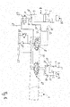
- Fig. 1 an example of a circuit diagram of a hydraulic system according to the invention is shown, wherein for the sake of simplicity, only two designed as working machines hydraulic cylinder 4 are shown.
- the left-hand hydraulic cylinder 4 is, for example, the hydraulic cylinder 4 for telescoping the main boom 1 of the aerial work platform according to FIG Fig. 2 while in Fig. 1 right hydraulic cylinder 4 is provided for aligning the basket 3.
- Each hydraulic cylinder 4 has a displaceably arranged in the hydraulic cylinder 4 piston 5 and is formed closed.
- the piston 5 separates the hydraulic cylinder 4 in two cavities 6, 7, wherein the piston 5, a piston rod 8 is mounted, which is performed by a correspondingly shaped opening 9 in a Zylinderend constitutional.
- Each cavity 6, 7 is associated with a leading into this cavity 6, 7 terminal 10, 11.
- the terminals 10, 11 serve as supply or return.
- a check valve 12, 13 is provided in the terminals 10, 11 respectively.
- an intermediate wall 14 is provided in the lower cavity 6 of the hydraulic cylinder 4.
- the intermediate wall 14 forms with the adjacent Zylinderendamide a subspace 15.
- This subspace 15 is connected via an opening 16 in the intermediate wall 14 with the adjacent cavity 6.
- In the subspace 15 opens one end of a bypass 17.
- the other end of the bypass 17 is connected to the serving in a desired operating condition as an inlet port of the right hydraulic cylinder 4.
- a valve 18 is provided, which is displaceable in two positions. In the illustrated position of the valve 18, the bypass 17 is closed.
- the intermediate wall 14 is arranged so that the piston 5 does not touch the intermediate wall 14 in the fully retracted state.
- the end position of the piston 5 in the fully retracted state is adjusted so that the piston 5 does not cover the relevant connection 10 on the circumference.
- a valve 19 is provided, which in the illustrated Embodiment in three different positions is displaced.
- the valves 19 may be arranged in a common control block 20.
- a pump is provided, which is driven by a motor, not shown.
- a tank 22 is provided in the present case in which the hydraulic fluid flowing back is collected.
- the pump is assigned a pressure protection 23.
- the hydraulic fluid in the upper cavity 7 is guided into the tank 22 via the valve 19 due to the decreasing volume of the upper cavity 7.
- the bypass according to the invention allows the following procedure for lowering the load, that is to say for retracting the left hydraulic cylinder 4 in the direction of the arrow 24.
- the outflow from the lower cavity 6 of the left hydraulic cylinder 4 is bypassed Hydraulic fluid passed directly into the inlet 10, for example, the lower cavity 6 of the right hydraulic cylinder 4.
- Hydraulic fluid passed directly into the inlet 10, for example, the lower cavity 6 of the right hydraulic cylinder 4.
- the valve 19 associated with the right-hand hydraulic cylinder 4 is in the left-hand position, as a result, the hydraulic fluid is introduced into the lower cavity 6 of the right-hand hydraulic cylinder 4 and the piston 5 is thus extended.
- the energy of the left hydraulic cylinder 4 provided by gravity can be used for the second hydraulic cylinder 4.
- hydraulic cylinders 4 may be provided in the hydraulic system, the simplicity in Fig. 1 are only indicated. These can also be integrated into the hydraulic system so that the energy stored in a hydraulic cylinder 4 by gravity is used for one or all other hydraulic cylinders 4.
- a bypass 17 is integrated into the resistance control so that the pressurized hydraulic oil of another working machine can be made available.
- energy can be introduced into the hydraulic system by the hydraulic cylinder 4 under load.
- the in Fig. 1 Master cylinder 4 shown on the left thus acts as an energy store for potential energy.
- any mode of operation may be performed.
- the above-described extension for example, the right master cylinder 4 against a load when retracting the left master cylinder 4 is possible by the stored energy.
- the acting as an energy storage left hydraulic cylinder 4 drops slowly.
- the possibility of a method of a working machine against a load depends only on the area ratios of the hydraulic cylinder 4 and the height of the loads. How high the stored energy is depends on the stroke of the "energy storing" hydraulic cylinder 4 and on the load.
Landscapes
- Engineering & Computer Science (AREA)
- Structural Engineering (AREA)
- Mechanical Engineering (AREA)
- Life Sciences & Earth Sciences (AREA)
- Transportation (AREA)
- Geology (AREA)
- Civil Engineering (AREA)
- Chemical & Material Sciences (AREA)
- Combustion & Propulsion (AREA)
- Physics & Mathematics (AREA)
- Fluid Mechanics (AREA)
- General Engineering & Computer Science (AREA)
- Forklifts And Lifting Vehicles (AREA)
- Fluid-Pressure Circuits (AREA)
Applications Claiming Priority (1)
| Application Number | Priority Date | Filing Date | Title |
|---|---|---|---|
| DE102011000239A DE102011000239A1 (de) | 2011-01-20 | 2011-01-20 | Hydrauliksystem mit zumindest einer Antriebsmaschine |
Publications (2)
| Publication Number | Publication Date |
|---|---|
| EP2479438A2 true EP2479438A2 (fr) | 2012-07-25 |
| EP2479438A3 EP2479438A3 (fr) | 2014-02-19 |
Family
ID=45558516
Family Applications (1)
| Application Number | Title | Priority Date | Filing Date |
|---|---|---|---|
| EP12151440.0A Withdrawn EP2479438A3 (fr) | 2011-01-20 | 2012-01-17 | Système hydraulique doté d'au moins une machine d'entraînement |
Country Status (3)
| Country | Link |
|---|---|
| US (1) | US20120186243A1 (fr) |
| EP (1) | EP2479438A3 (fr) |
| DE (1) | DE102011000239A1 (fr) |
Families Citing this family (1)
| Publication number | Priority date | Publication date | Assignee | Title |
|---|---|---|---|---|
| US9004842B2 (en) | 2011-10-10 | 2015-04-14 | Wastequip, Llc | Hoist apparatus |
Family Cites Families (7)
| Publication number | Priority date | Publication date | Assignee | Title |
|---|---|---|---|---|
| US3136220A (en) * | 1961-04-12 | 1964-06-09 | Gen Dynamics Corp | Controlled high energy actuator |
| FR2503214A2 (fr) * | 1980-05-28 | 1982-10-08 | Poclain Sa | Engin de terrassement du type chargeuse |
| US6502393B1 (en) * | 2000-09-08 | 2003-01-07 | Husco International, Inc. | Hydraulic system with cross function regeneration |
| CA2401201C (fr) * | 2001-09-12 | 2007-07-03 | Spray Air Technologies Ltd. | Actionner hydraulique pour le supportage d'une fleche |
| US6647718B2 (en) * | 2001-10-04 | 2003-11-18 | Husco International, Inc. | Electronically controlled hydraulic system for lowering a boom in an emergency |
| JP2003120604A (ja) * | 2001-10-11 | 2003-04-23 | Shin Caterpillar Mitsubishi Ltd | 流体圧回路 |
| DE60315997T2 (de) * | 2002-07-09 | 2008-05-15 | Hitachi Construction Machinery Co., Ltd. | Hydraulische antriebseinheit |
-
2011
- 2011-01-20 DE DE102011000239A patent/DE102011000239A1/de not_active Withdrawn
-
2012
- 2012-01-17 EP EP12151440.0A patent/EP2479438A3/fr not_active Withdrawn
- 2012-01-19 US US13/353,757 patent/US20120186243A1/en not_active Abandoned
Non-Patent Citations (1)
| Title |
|---|
| None |
Also Published As
| Publication number | Publication date |
|---|---|
| DE102011000239A1 (de) | 2012-07-26 |
| EP2479438A3 (fr) | 2014-02-19 |
| US20120186243A1 (en) | 2012-07-26 |
Similar Documents
| Publication | Publication Date | Title |
|---|---|---|
| EP3233544B1 (fr) | Châssis de véhicule automobile | |
| EP1915538B1 (fr) | Montage pour commander un cylindre d'entrainement hydraulique a double effet | |
| EP2855945B2 (fr) | Méthode pour l'opération d'un système hydraulique | |
| EP3459904B1 (fr) | Chariot de manutention, système hydraulique pour un chariot de manutention et procédé de fonctionnement d'un système hydraulique | |
| DE10004905C2 (de) | Verfahren und Vorrichtung zur Steuerung eines Hubzylinders insbesondere von Arbeitsmaschinen | |
| DE102006060351B3 (de) | Hydraulische Schaltungsanordnung mit Energierückgewinnung | |
| DE102016124118B4 (de) | Hydraulischer Antrieb mit Eil- und Lasthub | |
| DE10327132A1 (de) | Hydraulikschaltung für eine Ausleger-Zylinder-Kombination, welche eine Umlauffunktion aufweist | |
| WO2011060844A1 (fr) | Entraînement hydraulique à récupération d'énergie | |
| EP1780420B1 (fr) | Unité hydraulique d'alimentation en pression et unité de traitement électro-hydraulique | |
| DE69505203T2 (de) | Hydraulischer Kreislauf | |
| EP3159549B1 (fr) | Dispositif de recuperation d'energie hydraulique pour un engin de travail et engin de travail correspondant | |
| DE102004012382A1 (de) | Hydraulische Anordnung | |
| DE102014207669A1 (de) | Steuerungssystem für eine hydraulische Arbeitsmaschine | |
| EP2610049B1 (fr) | Procédé de commande d'une presse hydraulique | |
| EP3012463B1 (fr) | Agregat hydraulique | |
| DE202014006861U1 (de) | Arbeitsmaschine | |
| EP1781952B1 (fr) | Ensemble de commande hydraulique | |
| DE102018222425A1 (de) | Hydrostatischer Antrieb, insbesondere für eine Presse oder eine Spritzgießmaschine | |
| EP3527833A1 (fr) | Circuit d'alimentation à commande à pression réglable | |
| DE112016001329T5 (de) | Hydraulikkreis und Arbeitsmaschine | |
| DE102017107994B4 (de) | Kraftfahrzeug-Fahrgestell | |
| DE102011016542A1 (de) | Flurförderzeug, insbesondere Schubmaststapler mit einem Hubgerüst | |
| DE102007054036A1 (de) | Energierückgewinnungs- und Wiedernutzungsverfahren für ein Hydrauliksystem | |
| DE102012006551B4 (de) | Hydraulische Schaltungsanordnung |
Legal Events
| Date | Code | Title | Description |
|---|---|---|---|
| PUAI | Public reference made under article 153(3) epc to a published international application that has entered the european phase |
Free format text: ORIGINAL CODE: 0009012 |
|
| AK | Designated contracting states |
Kind code of ref document: A2 Designated state(s): AL AT BE BG CH CY CZ DE DK EE ES FI FR GB GR HR HU IE IS IT LI LT LU LV MC MK MT NL NO PL PT RO RS SE SI SK SM TR |
|
| AX | Request for extension of the european patent |
Extension state: BA ME |
|
| PUAL | Search report despatched |
Free format text: ORIGINAL CODE: 0009013 |
|
| AK | Designated contracting states |
Kind code of ref document: A3 Designated state(s): AL AT BE BG CH CY CZ DE DK EE ES FI FR GB GR HR HU IE IS IT LI LT LU LV MC MK MT NL NO PL PT RO RS SE SI SK SM TR |
|
| AX | Request for extension of the european patent |
Extension state: BA ME |
|
| RIC1 | Information provided on ipc code assigned before grant |
Ipc: B66F 9/22 20060101ALI20140110BHEP Ipc: F15B 11/024 20060101AFI20140110BHEP |
|
| STAA | Information on the status of an ep patent application or granted ep patent |
Free format text: STATUS: THE APPLICATION HAS BEEN WITHDRAWN |
|
| 18W | Application withdrawn |
Effective date: 20140812 |