EP2479449B1 - Embrayage hydrodynamique doté d'une préchambre à plusieurs niveaux - Google Patents
Embrayage hydrodynamique doté d'une préchambre à plusieurs niveaux Download PDFInfo
- Publication number
- EP2479449B1 EP2479449B1 EP20110151289 EP11151289A EP2479449B1 EP 2479449 B1 EP2479449 B1 EP 2479449B1 EP 20110151289 EP20110151289 EP 20110151289 EP 11151289 A EP11151289 A EP 11151289A EP 2479449 B1 EP2479449 B1 EP 2479449B1
- Authority
- EP
- European Patent Office
- Prior art keywords
- hydrodynamic coupling
- prechamber
- working chamber
- inlet channel
- radially
- Prior art date
- Legal status (The legal status is an assumption and is not a legal conclusion. Google has not performed a legal analysis and makes no representation as to the accuracy of the status listed.)
- Active
Links
Images


Classifications
-
- F—MECHANICAL ENGINEERING; LIGHTING; HEATING; WEAPONS; BLASTING
- F16—ENGINEERING ELEMENTS AND UNITS; GENERAL MEASURES FOR PRODUCING AND MAINTAINING EFFECTIVE FUNCTIONING OF MACHINES OR INSTALLATIONS; THERMAL INSULATION IN GENERAL
- F16D—COUPLINGS FOR TRANSMITTING ROTATION; CLUTCHES; BRAKES
- F16D33/00—Rotary fluid couplings or clutches of the hydrokinetic type
- F16D33/06—Rotary fluid couplings or clutches of the hydrokinetic type controlled by changing the amount of liquid in the working circuit
- F16D33/08—Rotary fluid couplings or clutches of the hydrokinetic type controlled by changing the amount of liquid in the working circuit by devices incorporated in the fluid coupling, with or without remote control
Definitions
- the present invention relates to a hydrodynamic coupling with a bladed outer wheel and a shell, which together form a working space and are rotatable together about a rotation axis, provided within the working space bladed inner wheel, which is arranged rotatable relative to the outer wheel and the shell about the axis of rotation is, and at least one prechamber, which is rotatably connected to the outer wheel, wherein a radially outer region of the prechamber via an inlet channel and a radially inner region of the prechamber are connected via a return passage to the working space.
- Such a hydrodynamic coupling is for example in the GB-A-2 159 252 described.
- Hydrodynamic clutches also called fluid clutches, turbo clutches or Föttinger clutches, are well known and are used, for example, as a startup and overload clutch for transmitting torque from a power to a work machine.
- a hydrodynamic coupling is simplified from a bladed outer wheel, the so-called impeller, which forms a housing together with a shell and is rotatably connected to a drive shaft.
- the housing encloses a working space and is at least partially filled with an oil or water-containing working fluid.
- Within the working space is a bladed inner wheel, the so-called turbine wheel, arranged, which is rotatably connected to a coaxially mounted to the drive shaft output shaft.
- the hydrodynamic clutches with an internal drive in which the internal wheel forms the impeller and the external wheel forms the turbine wheel.
- an engine connected to the drive shaft rotates the impeller, which converts the mechanical energy into kinetic fluid energy of the working fluid.
- this flow energy is converted back into mechanical energy, which drives the turbine wheel.
- a speed difference, the so-called slip, between the pump and the turbine wheel is necessary.
- hydrodynamic clutches limit the starting torque in a mechanical drive train and are torsional vibration damping, they are mainly used in drives for conveyor systems, such as belt conveyors, bucket elevators and chain conveyors and for paddlewheel drives, crushers, roller presses, mixers, large fans, boiler feed pumps, large compressors, centrifuges and in Auxiliary drives used for mills.
- the material-saving starting behavior increases the service life of connected machines.
- the working fluid rests statically in the hydrodynamic coupling and fills the lower area of the working space and the lower area of the prechamber.
- the impeller is set in rotation via the drive shaft.
- the increasing centrifugal forces with increasing speed Press the working fluid to the radial outer wall of the working space.
- the working fluid located in the antechamber flows through the inlet channel with a time delay into the working space.
- the low level of the working fluid in the working space in start-up state allows the hydrodynamic coupling anaria with a lower starting torque.
- the hydrodynamic coupling is complicated and expensive to manufacture due to the electronic components.
- the electronic components are susceptible to interference and must be supplied with electronic power.
- Object of the present invention is therefore to provide a possible maintenance-free hydrodynamic coupling, which has a suitable starting torque, which has no high maximum value and also does not extend the starting time too strong achieved, has a compact design and is easy and inexpensive to manufacture.
- the at least one pre-chamber is connected via at least two radially spaced inlet channels and / or at least one substantially radially extending, slot-shaped inlet channel with the working space.
- the invention is therefore based on the consideration to change the volume flow of the working fluid from the prechamber into the working space as a function of the level of the working fluid in the prechamber.
- the invention initially proposes to connect the at least one pre-chamber via at least two radially spaced inlet channels with the working space.
- the working fluid is due to the acting centrifugal forces pressed against the radial outer wall of the antechamber.
- the working fluid flows through both inlet channels in the working space.
- the liquid level in the antechamber drops below the radially inner inflow channel, the working fluid only flows into the working space via the radially outer inflow channel. This results in the start-up state, a high volume flow of the working fluid from the antechamber into the working space, which drops in operation with decreasing liquid level in the antechamber.
- the invention proposes to connect the at least one antechamber via at least one substantially radially extending, slot-shaped inlet channel with the working space.
- the working fluid is pressed against the radial outer wall of the pre-chamber due to the centrifugal forces acting on it.
- the liquid level in the antechamber is above the slot-shaped inlet channel, so that the working channel flows through the inlet channel.
- the liquid level in the pre-chamber drops.
- the flow-through cross section of the inlet channel decreases. As a result, reduces the flow of the working fluid from the antechamber into the working space.
- the throttling effect of the inlet channel increases.
- Due to the initially high volume flow of the working fluid in the starting state of the pre-chamber in the working space can also be a large load torque, which are provided for example as a breakaway torque must be overcome by the torque increase of the hydrodynamic coupling.
- the liquid level drops in the prechamber in a time-dependent manner, as a result of which the volume flow of the working fluid from the prechamber into the working space decreases.
- the course of the torque curve can be determined very accurately by changing the number of radially spaced inlet channels and by selecting the flow cross sections, which can take any geometric shape, in particular a round, rectangular or slot-shaped.
- the outer wheel can be rotatably connected to a drive shaft and the inner wheel with an output shaft.
- the Nachström a working fluid from the prechamber into the working space in the starting process in the so-called Indeedradantrieb, i. the outer wheel works as impeller and the inner wheel as turbine wheel, to be better determined compared to an internal wheel drive.
- radially spaced inlet channels are provided, wherein in each case a radially further inwardly located inlet channel has a larger flow cross-section than a radially outer inlet channel.
- a slot-shaped inlet channel in which the ratio between height and average width is 4: 1 or more. From the ratio of 4: 1, the slot-shaped inlet channel has the same good properties as at least two radially spaced feed channels.
- the at least one slit-shaped Inlet channel to a variable width, which increases in a preferred manner with decreasing distance to the axis of rotation, in particular continuously. This results in decreasing liquid level, a continuously decreasing volume flow of the working fluid from the antechamber via the inlet channel into the working space.
- the at least one pre-chamber can be connected to the working space via a plurality of inlet channels, which are arranged at the same distance from the axis of rotation.
- pre-chamber has an annular interior. This makes the antechamber simple and inexpensive to manufacture.
- At least one further prechamber is additionally provided on the opposite side of the working chamber and the outer wheel rotatably connected, the radially outer region are connected via an inlet channel and its radially inner region via a return channel to the working space.
- the inlet channels of the lying on the opposite sides of the working chamber atria are radially spaced from each other and / or have different sized flow cross sections.
- the Vorschsystem behaves from at least two opposing pre-chambers as well as a volume equal in size pre-chamber with radially spaced feed channels.
- the working fluid is forced by the centrifugal forces acting on the radial outer walls of the antechambers.
- the liquid level in both prechambers is above the inlet channels, so that the working fluid flows into the working chamber via both inlet channels. If the Liquid level drops in one of the two antechambers below the radially inner inlet channel of the Vorhuntsystems, the working fluid flows only through the radially outer inlet channel of the other pre-chamber in the working space. This results in the start-up state, a high volume flow of the working fluid from the antechambers in the working space, which drops in operation with decreasing liquid level in the antechambers.
- the volume flow from the prechambers into the working space can be determined by the choice of different flow cross sections of the inflow channels.
- An antechamber system with two opposing pre-chambers behaves the same way as an antechamber with multiple feed channels.
- the liquid level in a pre-chamber with a large flow cross-section of the inlet channel decreases significantly faster compared to a volumetrically equal pre-chamber with a small flow cross-section.
- the liquid level in both prechambers is above the inlet channels, so that the working fluid flows into the working chamber via both inlet channels.
- the working fluid only flows via the inlet channel with the smaller flow cross section of the other prechamber into the working chamber. This results in the start-up state, a high volume flow of the working fluid from the antechamber into the working space, which drops in operation with decreasing liquid level in the antechambers.
- the course of the torque characteristic can be determined very accurately by changing the prechamber volume and the choice of the flow cross sections of the inlet channels.
- the opposing prechambers each have an annular interior. This makes the atria easy and inexpensive to manufacture.
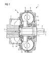
- FIG. 1 a hydrodynamic coupling 1 according to a first embodiment of the present invention is shown.
- the hydrodynamic coupling 1 is used to transmit a torque from a drive shaft 2 to an output shaft 3.
- the hydrodynamic coupling 1 a rotatable about a rotation axis L arranged housing 4, which consists of an outer wheel 5 with radial blades, a shell 6 and a pre-chamber housing 7.
- the outer wheel 5 is rotatably connected to a drive shaft 2 and operates as a pump. Together with the shell 6, it defines a toroidal working space 8, which is partially filled with an oil or water-containing working fluid 9.
- an inner wheel 10 is arranged with radially directed blades, which is rotatably connected via a hub 11 with a coaxial with the drive shaft 2 mounted output shaft 3 and operates as a turbine wheel.
- the housing 4 is supported via rolling bearings 12.
- annular pre-chamber 13 is formed on the drive side, which is connected in a radially inner region via a return channel 14 and in a radially outer region via two radially spaced inlet channels 15, 16 with the working space 8.
- the radially inner inlet channel 15 has a larger flow cross-section than the radially outer inlet channel 16.
- the flow cross sections of the inlet channels 15, 16 are round here, but they can basically assume any geometric shape and in particular be formed rectangular or conical.
- pre-chamber 13 can be connected to the working space 8 via further inlet channels.
- the working fluid 9 fills the lower area of the working space 8 and the lower area of the prechamber 13.
- the degree of filling FG of the hydrodynamic coupling 1 denotes the ratio of the total volume of the hydrodynamic coupling 1 and the volume of the filled working fluid 9.
- the impeller 5 Via the drive shaft 2, the impeller 5 is set in rotation, whereby the working fluid 9 is pressed due to the centrifugal forces on the radial outer walls of the working space 8 and the pre-chamber 13.
- the prechamber 13 has a liquid level F which is almost unchanged in comparison with the standstill.
- the small flow cross sections of the inlet channels 15, 16 act as a throttle, so that the working fluid 9 flows from the prechamber 13 via the inlet channels 15, 16 into the working space 8 with a delay. Due to the small filling quantity of the working fluid 9 in the working space 8 in the starting state, the hydrodynamic coupling 1 travels, as in FIG FIG. 4 shown with a low starting torque.
- the working liquid 9 flows from the pre-chamber 13 only via the radially outer inlet channel 16 into the working space 8.
- the diminished Nachspeise the antechamber 13 flattens the torque curve, as in of the FIG. 4 shown, from.
- the hydrodynamic coupling 1 achieves a lower maximum torque B in comparison to a maximum torque A of a previously known hydrodynamic coupling with an antechamber without radially spaced feed channels.
- the service life of a connected conveyor belt can be increased or the conveyor belt can be made lighter or lighter in size, to make it cheaper.
- FIG. 5 a hydrodynamic coupling 17 according to a second embodiment of the present invention.
- the structure of the hydrodynamic coupling 17 corresponds to the general structure of the hydrodynamic coupling of the FIG. 1 .
- the pre-chamber 18 of the second embodiment is not connected via two radially spaced inlet channels but via a radially extending and slot-shaped inlet channel 19 with the working space 8, the width of which increases continuously with decreasing distance from the axis of rotation L.
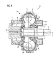
- FIG. 8 a hydrodynamic coupling 20 according to a third embodiment of the present invention.
- the structure of the hydrodynamic coupling 20 corresponds to the general basic structure of the hydrodynamic coupling 1 of the FIG. 1 .
- the third embodiment in a housing 21 in addition to an antechamber 22 on the side opposite the antechamber 22 side of a working space 23, a further, smaller volume pre-chamber 24 on.
- Both pre-chambers 22, 24 are in the housing 21 which is arranged rotatable about a rotation axis L and in addition to the outer wheel 5, the shell 6 and the pre-chamber housing 7 consists of an outer shell 25, arranged and rotatably connected to the outer wheel 5.
- the pre-chambers 22, 24 are each connected in a radially inner region via a return channel 26, 27 and in a radially outer region via an inlet channel 28, 29 with the working space 23.
- Both inlet channels 28, 29 have the same flow cross-sections, wherein the inlet channel 28 is arranged radially further outboard than the inlet channel 29.
- the prechamber system behaves from the two opposing prechambers 22, 24 with radially spaced supply passages 28, 29 as well as a volumetrically equal prechamber 13 according to the first embodiment of the present invention.
- the Liquid level F of the working fluid 9 in the antechamber 22, 24, as in the FIG. 8 shown above the radially spaced inlet channels 28, 29, the working fluid 9 flows from both antechambers 22, 24 via the inlet channels 28, 29 in the working space 23rd
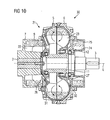
- a hydrodynamic coupling 30 according to a fourth embodiment of the present invention is shown.
- the structure of the hydrodynamic coupling 30 corresponds to the general basic structure of the hydrodynamic coupling 20 from the FIG. 8 .
- the opposing inlet channels 28, 29 of the two pre-chambers 22, 24 are not radially spaced from each other but are arranged at an equal distance from the axis of rotation L.
- the inlet channel 31 of the prechamber 22 has a smaller flow cross section than the opposite inlet channel 32 of the further prechamber 24.
- the prechamber system behaves from the two opposing prechambers 22, 24 as well as an equal volume prechamber 13 according to the first embodiment of the present invention.
- the liquid level F of the working fluid 9 in the further prechamber 24 drops significantly faster than in the prechamber 22 due to the larger flow cross section of the inflow channel 32 and the small volume.
- the working fluid 9 flows only from the pre-chamber 22 via the inlet channel 31 into the working space 23 by the diminished Nachspeise flat Torque characteristic in an analogous manner to the first embodiment according to FIG. 4 from.
- a stator in addition to the outer and the inner wheel 5, 10, a stator can be provided to operate a hydrodynamic converter analog.
Landscapes
- Engineering & Computer Science (AREA)
- General Engineering & Computer Science (AREA)
- Mechanical Engineering (AREA)
- Structures Of Non-Positive Displacement Pumps (AREA)
- Hydraulic Motors (AREA)
Claims (12)
- Embrayage (1,17) hydrodynamique ayant une roue (5) extérieure à aubes et une coquille (6) qui forment ensemble un espace (8) de travail et qui sont montées tournantes conjointement autour d'un axe (L) de rotation, une roue (10) intérieure à aubes prévue à l'intérieure de l'espace (8) de travail, qui est montée tournante autour de l'axe (L) de rotation par rapport à la roue (5) extérieure et à la coquille (6), ainsi qu'au moins une antichambre (13,18) qui est solidaire en rotation de la roue (5) extérieure, une partie extérieure radialement de l'antichambre (13,18) communiquant par un canal (16,19) d'accès avec l'espace (8) de travail et une partie intérieure radialement de l'antichambre (13,18) communiquant avec l'espace (8) de travail par un canal (14) de retour, caractérisé en ce que la au moins une antichambre (13,18) communique avec l'espace (8) de travail par au moins deux canaux (15,16) d'accès à distance radialement l'un de l'autre et/ou par au moins un canal (19) d'accès en forme de fente s'étendant sensiblement radialement.
- Embrayage (1,17) hydrodynamique suivant la revendication 1,
caractérisé en ce que
la roue extérieure est solidaire en rotation d'un arbre (2) d'entrée et la roue (10) intérieure d'un arbre (3) de sortie. - Embrayage (1,17) hydrodynamique suivant l'une des revendications 1 ou 2,
caractérisé en ce que
il est prévu des canaux (15,16) d'accès à distance les uns des autres radialement, respectivement un canal (15) d'accès plus à l'intérieur radialement ayant une section transversale d'écoulement plus grande qu'un canal (16) d'accès plus à l'extérieur radialement. - Embrayage (1,17) hydrodynamique suivant l'une des revendications 1 ou 2,
caractérisé en ce que
il est prévu un canal (19) d'accès en forme de fente, dans lequel le rapport entre la hauteur et la largeur au milieu est supérieur ou égal 4:1. - Embrayage (1,17) hydrodynamique suivant la revendication 4,
caractérisé en ce que
le au moins un canal (19) d'accès en forme de fente a une largeur variable. - Embrayage (1,17) hydrodynamique suivant la revendication 5,
caractérisé en ce que
la largeur du au moins un canal (19) d'accès en forme de fente augmente au fur et à mesure que diminue la distance à l'axe (L) de rotation. - Embrayage (1,17) hydrodynamique suivant la revendication 6,
caractérisé en ce que
la largeur du au moins un canal(19) d'accès en forme de fente augmente d'une manière continue au fur et à mesure que diminue la distance à l'axe (L) de rotation. - Embrayage (1,17) hydrodynamique suivant l'une des revendications précédentes,
caractérisé en ce que
la au moins une antichambre (13,18) communique avec l'espace de travail par plusieurs canaux d'accès qui sont disposés à une même distance de l'axe (L) de rotation. - Embrayage (1,17) hydrodynamique suivant l'une des revendications précédentes,
caractérisé en ce que
il est prévu plusieurs antichambres distinctes les unes des autres dans la direction périphérique. - Embrayage (1,17) hydrodynamique suivant l'une des revendications 1 ou 8,
caractérisé en ce que
l'antichambre (13,18) a un espace intérieur annulaire. - Embrayage (20,30) hydrodynamique comprenant une roue (5) extérieure à aubes et une coquille (6) qui forment ensemble un espace (23) de travail et qui sont montées tournantes conjointement autour d'un axe (L) de rotation, une roue (10) intérieure à aubes prévue à l'intérieure de l'espace (23) de travail qui est montée tournante autour de l'axe (L) de rotation par rapport à la roue (5) extérieure et à la coquille (6), ainsi qu'au moins une antichambre (22) qui est solidaire en rotation de la roue (5) extérieure, une partie extérieure radialement de l'antichambre (22) communiquant par un canal (28,31) d'accès avec l'espace (23) de travail et une partie intérieure radialement de l'antichambre (22) communiquant avec l'espace (23) de travail par un canal (26) de retour, notamment suivant l'une des revendications 1 à 10, caractérisé en ce que, du côté de l'espace (23) de travail opposé à l'antichambre (22), est prévu, en outre, au moins une autre antichambre (24) qui est solidaire en rotation de la roue (5) extérieure, dont la partie extérieure radialement communique par un canal (29,32) d'accès avec l'espace (23) de travail et dont la partie intérieure radialement communique, par un canal (27) de retour, avec l'espace (23) de travail et en ce que les canaux (28,31,29,32) d'accès des antichambres (22,24), se trouvant sur les côtés opposés de l'espace (23) de travail, sont à distance radialement les uns des autres et/ou ont des sections transversales d'écoulement de dimensions différentes.
- Embrayage (1,17) hydrodynamique suivant la revendication 11,
caractérisé en ce que
les antichambres (22,24) opposées ont respectivement un espace intérieur annulaire.
Priority Applications (3)
| Application Number | Priority Date | Filing Date | Title |
|---|---|---|---|
| ES11151289T ES2433265T3 (es) | 2011-01-18 | 2011-01-18 | Acoplamiento hidráulico con antecámara de varias etapas |
| EP20110151289 EP2479449B1 (fr) | 2011-01-18 | 2011-01-18 | Embrayage hydrodynamique doté d'une préchambre à plusieurs niveaux |
| CN201210016803.7A CN102606645B (zh) | 2011-01-18 | 2012-01-18 | 具有多级的前室的液压耦合器 |
Applications Claiming Priority (1)
| Application Number | Priority Date | Filing Date | Title |
|---|---|---|---|
| EP20110151289 EP2479449B1 (fr) | 2011-01-18 | 2011-01-18 | Embrayage hydrodynamique doté d'une préchambre à plusieurs niveaux |
Publications (2)
| Publication Number | Publication Date |
|---|---|
| EP2479449A1 EP2479449A1 (fr) | 2012-07-25 |
| EP2479449B1 true EP2479449B1 (fr) | 2013-07-31 |
Family
ID=43989796
Family Applications (1)
| Application Number | Title | Priority Date | Filing Date |
|---|---|---|---|
| EP20110151289 Active EP2479449B1 (fr) | 2011-01-18 | 2011-01-18 | Embrayage hydrodynamique doté d'une préchambre à plusieurs niveaux |
Country Status (3)
| Country | Link |
|---|---|
| EP (1) | EP2479449B1 (fr) |
| CN (1) | CN102606645B (fr) |
| ES (1) | ES2433265T3 (fr) |
Families Citing this family (3)
| Publication number | Priority date | Publication date | Assignee | Title |
|---|---|---|---|---|
| CN105370768A (zh) * | 2015-12-10 | 2016-03-02 | 陕西法士特齿轮有限责任公司 | 一种串联液力缓速器 |
| CN111927932A (zh) * | 2020-09-15 | 2020-11-13 | 中煤张家口煤矿机械有限责任公司 | 一种自冷却限矩型液力偶合器 |
| US12104662B1 (en) * | 2023-09-12 | 2024-10-01 | Cheng-Jiang Hou | Coupling |
Family Cites Families (11)
| Publication number | Priority date | Publication date | Assignee | Title |
|---|---|---|---|---|
| FR2087138A5 (fr) * | 1970-05-06 | 1971-12-31 | Ferodo Sa | |
| GB1484011A (en) * | 1973-08-09 | 1977-08-24 | Fluidrive Eng Co Ltd | Fluid couplings |
| DE3318462C2 (de) | 1983-05-20 | 1986-10-09 | Bergwerksverband Gmbh, 4300 Essen | Hydrodynamische Kupplung |
| DE8414929U1 (de) * | 1984-05-16 | 1984-08-09 | Voith-Turbo Gmbh & Co Kg, 7180 Crailsheim | Hydrodynamische kupplung |
| DE3522174C1 (de) * | 1985-06-21 | 1986-05-22 | Voith-Turbo Gmbh & Co Kg, 7180 Crailsheim | Hydrodynamische Kupplung |
| DD270744A1 (de) * | 1988-04-19 | 1989-08-09 | Stroemungsmasch Veb | Hydrodynamische kupplung |
| DE19802524B4 (de) * | 1998-01-26 | 2005-12-22 | Voith Turbo Gmbh & Co. Kg | Hydrodynamische Kupplung |
| DE19859428A1 (de) * | 1998-12-22 | 2000-07-06 | Voith Turbo Kg | Hydrodynamische Kupplung |
| DE10163486C1 (de) * | 2001-12-21 | 2003-10-02 | Voith Turbo Kg | Hydrodynamische Baueinheit |
| DE102004001047B4 (de) * | 2004-01-03 | 2005-12-22 | Voith Turbo Gmbh & Co. Kg | Hydrodynamische Maschine |
| DE102007032212A1 (de) * | 2007-07-11 | 2009-01-15 | Voith Patent Gmbh | Hydrodynamische Kupplung |
-
2011
- 2011-01-18 ES ES11151289T patent/ES2433265T3/es active Active
- 2011-01-18 EP EP20110151289 patent/EP2479449B1/fr active Active
-
2012
- 2012-01-18 CN CN201210016803.7A patent/CN102606645B/zh active Active
Also Published As
| Publication number | Publication date |
|---|---|
| CN102606645B (zh) | 2016-08-24 |
| CN102606645A (zh) | 2012-07-25 |
| EP2479449A1 (fr) | 2012-07-25 |
| ES2433265T3 (es) | 2013-12-10 |
Similar Documents
| Publication | Publication Date | Title |
|---|---|---|
| DE3340174C2 (fr) | ||
| EP2479449B1 (fr) | Embrayage hydrodynamique doté d'une préchambre à plusieurs niveaux | |
| WO2007124715A1 (fr) | Moyen de fixation utilisant la languette d'une aube de turbine pour un logement de ressort amortisseur d'un convertisseur de couple et procédé de fabrication du moyen de fixation | |
| EP2207979B1 (fr) | Machine hydrodynamique, notamment retardateur hydrodynamique | |
| WO2007118449A2 (fr) | Forme toroïdale pour convertisseur de couple | |
| EP3015708B1 (fr) | Pompes a cellules battantes presentant un comportement de demarrage ameliore | |
| EP2146115B1 (fr) | Convertisseur de couple hydrodynamique | |
| WO2007118445A2 (fr) | Formes de tores pour convertisseur de couple | |
| DE112013004575T5 (de) | Statoranordnung für Drehmomentwandler | |
| EP2175168A1 (fr) | Convertisseur de couple hydrodynamique | |
| DE10004952C2 (de) | Überbrückungsvorrichtung für einen Drehmomentwandler | |
| EP2479448B1 (fr) | Embrayage hydrodynamique doté d'une préchambre à plusieurs niveaux | |
| DE19942578C2 (de) | Hydrodynamische Kupplung | |
| DE102005043756A1 (de) | Hydrodynamische Kupplung | |
| DE102005050219B3 (de) | Hydrodynamische Maschine | |
| DE10005516C2 (de) | Überbrückungsvorrichtung für einen Drehmomentwandler | |
| DE602004002121T2 (de) | Flüssigkeitskupplung | |
| CH620024A5 (fr) | ||
| DE102004016296A1 (de) | Hydrodynamische Baueinheit | |
| EP3880989B1 (fr) | Convertisseur hydrodynamique | |
| EP3519714A1 (fr) | Contour de roue à aubes | |
| EP2131056B1 (fr) | Retardateur hydrodynamique fonctionnant selon le principe d'arrivée et d'écoulement de flux tangentiel | |
| AT135265B (de) | Flüssigkeitskupplung oder -getriebe der kinetischen Gattung. | |
| EP0943830B1 (fr) | Accouplement hydrodynamique | |
| EP0158126B1 (fr) | Machine fluidodynamique et système de commande s'y rapportant |
Legal Events
| Date | Code | Title | Description |
|---|---|---|---|
| PUAI | Public reference made under article 153(3) epc to a published international application that has entered the european phase |
Free format text: ORIGINAL CODE: 0009012 |
|
| AK | Designated contracting states |
Kind code of ref document: A1 Designated state(s): AL AT BE BG CH CY CZ DE DK EE ES FI FR GB GR HR HU IE IS IT LI LT LU LV MC MK MT NL NO PL PT RO RS SE SI SK SM TR |
|
| AX | Request for extension of the european patent |
Extension state: BA ME |
|
| 17P | Request for examination filed |
Effective date: 20121119 |
|
| GRAP | Despatch of communication of intention to grant a patent |
Free format text: ORIGINAL CODE: EPIDOSNIGR1 |
|
| RAP1 | Party data changed (applicant data changed or rights of an application transferred) |
Owner name: SIEMENS AKTIENGESELLSCHAFT |
|
| GRAS | Grant fee paid |
Free format text: ORIGINAL CODE: EPIDOSNIGR3 |
|
| GRAA | (expected) grant |
Free format text: ORIGINAL CODE: 0009210 |
|
| AK | Designated contracting states |
Kind code of ref document: B1 Designated state(s): AL AT BE BG CH CY CZ DE DK EE ES FI FR GB GR HR HU IE IS IT LI LT LU LV MC MK MT NL NO PL PT RO RS SE SI SK SM TR |
|
| REG | Reference to a national code |
Ref country code: GB Ref legal event code: FG4D Free format text: NOT ENGLISH Ref country code: CH Ref legal event code: EP |
|
| REG | Reference to a national code |
Ref country code: AT Ref legal event code: REF Ref document number: 624837 Country of ref document: AT Kind code of ref document: T Effective date: 20130815 |
|
| REG | Reference to a national code |
Ref country code: IE Ref legal event code: FG4D Free format text: LANGUAGE OF EP DOCUMENT: GERMAN |
|
| REG | Reference to a national code |
Ref country code: DE Ref legal event code: R096 Ref document number: 502011001112 Country of ref document: DE Effective date: 20131002 |
|
| REG | Reference to a national code |
Ref country code: ES Ref legal event code: FG2A Ref document number: 2433265 Country of ref document: ES Kind code of ref document: T3 Effective date: 20131210 |
|
| REG | Reference to a national code |
Ref country code: NL Ref legal event code: VDEP Effective date: 20130731 |
|
| REG | Reference to a national code |
Ref country code: LT Ref legal event code: MG4D |
|
| PG25 | Lapsed in a contracting state [announced via postgrant information from national office to epo] |
Ref country code: IS Free format text: LAPSE BECAUSE OF FAILURE TO SUBMIT A TRANSLATION OF THE DESCRIPTION OR TO PAY THE FEE WITHIN THE PRESCRIBED TIME-LIMIT Effective date: 20131130 Ref country code: HR Free format text: LAPSE BECAUSE OF FAILURE TO SUBMIT A TRANSLATION OF THE DESCRIPTION OR TO PAY THE FEE WITHIN THE PRESCRIBED TIME-LIMIT Effective date: 20130731 Ref country code: SE Free format text: LAPSE BECAUSE OF FAILURE TO SUBMIT A TRANSLATION OF THE DESCRIPTION OR TO PAY THE FEE WITHIN THE PRESCRIBED TIME-LIMIT Effective date: 20130731 Ref country code: PT Free format text: LAPSE BECAUSE OF FAILURE TO SUBMIT A TRANSLATION OF THE DESCRIPTION OR TO PAY THE FEE WITHIN THE PRESCRIBED TIME-LIMIT Effective date: 20131202 Ref country code: LT Free format text: LAPSE BECAUSE OF FAILURE TO SUBMIT A TRANSLATION OF THE DESCRIPTION OR TO PAY THE FEE WITHIN THE PRESCRIBED TIME-LIMIT Effective date: 20130731 Ref country code: CY Free format text: LAPSE BECAUSE OF FAILURE TO SUBMIT A TRANSLATION OF THE DESCRIPTION OR TO PAY THE FEE WITHIN THE PRESCRIBED TIME-LIMIT Effective date: 20130904 Ref country code: NO Free format text: LAPSE BECAUSE OF FAILURE TO SUBMIT A TRANSLATION OF THE DESCRIPTION OR TO PAY THE FEE WITHIN THE PRESCRIBED TIME-LIMIT Effective date: 20131031 |
|
| PG25 | Lapsed in a contracting state [announced via postgrant information from national office to epo] |
Ref country code: PL Free format text: LAPSE BECAUSE OF FAILURE TO SUBMIT A TRANSLATION OF THE DESCRIPTION OR TO PAY THE FEE WITHIN THE PRESCRIBED TIME-LIMIT Effective date: 20130731 Ref country code: GR Free format text: LAPSE BECAUSE OF FAILURE TO SUBMIT A TRANSLATION OF THE DESCRIPTION OR TO PAY THE FEE WITHIN THE PRESCRIBED TIME-LIMIT Effective date: 20131101 Ref country code: FI Free format text: LAPSE BECAUSE OF FAILURE TO SUBMIT A TRANSLATION OF THE DESCRIPTION OR TO PAY THE FEE WITHIN THE PRESCRIBED TIME-LIMIT Effective date: 20130731 Ref country code: LV Free format text: LAPSE BECAUSE OF FAILURE TO SUBMIT A TRANSLATION OF THE DESCRIPTION OR TO PAY THE FEE WITHIN THE PRESCRIBED TIME-LIMIT Effective date: 20130731 Ref country code: SI Free format text: LAPSE BECAUSE OF FAILURE TO SUBMIT A TRANSLATION OF THE DESCRIPTION OR TO PAY THE FEE WITHIN THE PRESCRIBED TIME-LIMIT Effective date: 20130731 Ref country code: NL Free format text: LAPSE BECAUSE OF FAILURE TO SUBMIT A TRANSLATION OF THE DESCRIPTION OR TO PAY THE FEE WITHIN THE PRESCRIBED TIME-LIMIT Effective date: 20130731 |
|
| PG25 | Lapsed in a contracting state [announced via postgrant information from national office to epo] |
Ref country code: CY Free format text: LAPSE BECAUSE OF FAILURE TO SUBMIT A TRANSLATION OF THE DESCRIPTION OR TO PAY THE FEE WITHIN THE PRESCRIBED TIME-LIMIT Effective date: 20130731 |
|
| PG25 | Lapsed in a contracting state [announced via postgrant information from national office to epo] |
Ref country code: DK Free format text: LAPSE BECAUSE OF FAILURE TO SUBMIT A TRANSLATION OF THE DESCRIPTION OR TO PAY THE FEE WITHIN THE PRESCRIBED TIME-LIMIT Effective date: 20130731 Ref country code: SK Free format text: LAPSE BECAUSE OF FAILURE TO SUBMIT A TRANSLATION OF THE DESCRIPTION OR TO PAY THE FEE WITHIN THE PRESCRIBED TIME-LIMIT Effective date: 20130731 Ref country code: EE Free format text: LAPSE BECAUSE OF FAILURE TO SUBMIT A TRANSLATION OF THE DESCRIPTION OR TO PAY THE FEE WITHIN THE PRESCRIBED TIME-LIMIT Effective date: 20130731 Ref country code: CZ Free format text: LAPSE BECAUSE OF FAILURE TO SUBMIT A TRANSLATION OF THE DESCRIPTION OR TO PAY THE FEE WITHIN THE PRESCRIBED TIME-LIMIT Effective date: 20130731 Ref country code: RO Free format text: LAPSE BECAUSE OF FAILURE TO SUBMIT A TRANSLATION OF THE DESCRIPTION OR TO PAY THE FEE WITHIN THE PRESCRIBED TIME-LIMIT Effective date: 20130731 |
|
| PLBE | No opposition filed within time limit |
Free format text: ORIGINAL CODE: 0009261 |
|
| STAA | Information on the status of an ep patent application or granted ep patent |
Free format text: STATUS: NO OPPOSITION FILED WITHIN TIME LIMIT |
|
| 26N | No opposition filed |
Effective date: 20140502 |
|
| REG | Reference to a national code |
Ref country code: DE Ref legal event code: R097 Ref document number: 502011001112 Country of ref document: DE Effective date: 20140502 |
|
| PG25 | Lapsed in a contracting state [announced via postgrant information from national office to epo] |
Ref country code: LU Free format text: LAPSE BECAUSE OF FAILURE TO SUBMIT A TRANSLATION OF THE DESCRIPTION OR TO PAY THE FEE WITHIN THE PRESCRIBED TIME-LIMIT Effective date: 20140118 |
|
| REG | Reference to a national code |
Ref country code: CH Ref legal event code: PL |
|
| PG25 | Lapsed in a contracting state [announced via postgrant information from national office to epo] |
Ref country code: CH Free format text: LAPSE BECAUSE OF NON-PAYMENT OF DUE FEES Effective date: 20140131 Ref country code: LI Free format text: LAPSE BECAUSE OF NON-PAYMENT OF DUE FEES Effective date: 20140131 |
|
| REG | Reference to a national code |
Ref country code: IE Ref legal event code: MM4A |
|
| PG25 | Lapsed in a contracting state [announced via postgrant information from national office to epo] |
Ref country code: IE Free format text: LAPSE BECAUSE OF NON-PAYMENT OF DUE FEES Effective date: 20140118 |
|
| PG25 | Lapsed in a contracting state [announced via postgrant information from national office to epo] |
Ref country code: MC Free format text: LAPSE BECAUSE OF FAILURE TO SUBMIT A TRANSLATION OF THE DESCRIPTION OR TO PAY THE FEE WITHIN THE PRESCRIBED TIME-LIMIT Effective date: 20130731 |
|
| REG | Reference to a national code |
Ref country code: FR Ref legal event code: PLFP Year of fee payment: 6 |
|
| PG25 | Lapsed in a contracting state [announced via postgrant information from national office to epo] |
Ref country code: MT Free format text: LAPSE BECAUSE OF FAILURE TO SUBMIT A TRANSLATION OF THE DESCRIPTION OR TO PAY THE FEE WITHIN THE PRESCRIBED TIME-LIMIT Effective date: 20130731 |
|
| PG25 | Lapsed in a contracting state [announced via postgrant information from national office to epo] |
Ref country code: SM Free format text: LAPSE BECAUSE OF FAILURE TO SUBMIT A TRANSLATION OF THE DESCRIPTION OR TO PAY THE FEE WITHIN THE PRESCRIBED TIME-LIMIT Effective date: 20130731 |
|
| PG25 | Lapsed in a contracting state [announced via postgrant information from national office to epo] |
Ref country code: RS Free format text: LAPSE BECAUSE OF NON-PAYMENT OF DUE FEES Effective date: 20130731 Ref country code: BG Free format text: LAPSE BECAUSE OF FAILURE TO SUBMIT A TRANSLATION OF THE DESCRIPTION OR TO PAY THE FEE WITHIN THE PRESCRIBED TIME-LIMIT Effective date: 20130731 |
|
| PG25 | Lapsed in a contracting state [announced via postgrant information from national office to epo] |
Ref country code: HU Free format text: LAPSE BECAUSE OF FAILURE TO SUBMIT A TRANSLATION OF THE DESCRIPTION OR TO PAY THE FEE WITHIN THE PRESCRIBED TIME-LIMIT; INVALID AB INITIO Effective date: 20110118 Ref country code: TR Free format text: LAPSE BECAUSE OF FAILURE TO SUBMIT A TRANSLATION OF THE DESCRIPTION OR TO PAY THE FEE WITHIN THE PRESCRIBED TIME-LIMIT Effective date: 20130731 |
|
| REG | Reference to a national code |
Ref country code: FR Ref legal event code: PLFP Year of fee payment: 7 |
|
| REG | Reference to a national code |
Ref country code: AT Ref legal event code: MM01 Ref document number: 624837 Country of ref document: AT Kind code of ref document: T Effective date: 20160118 |
|
| PG25 | Lapsed in a contracting state [announced via postgrant information from national office to epo] |
Ref country code: AT Free format text: LAPSE BECAUSE OF NON-PAYMENT OF DUE FEES Effective date: 20160118 |
|
| REG | Reference to a national code |
Ref country code: DE Ref legal event code: R081 Ref document number: 502011001112 Country of ref document: DE Owner name: FLENDER GMBH, DE Free format text: FORMER OWNER: SIEMENS AKTIENGESELLSCHAFT, 80333 MUENCHEN, DE |
|
| REG | Reference to a national code |
Ref country code: ES Ref legal event code: PC2A Owner name: FLENDER GMBH Effective date: 20171219 |
|
| REG | Reference to a national code |
Ref country code: GB Ref legal event code: 732E Free format text: REGISTERED BETWEEN 20171207 AND 20171213 |
|
| REG | Reference to a national code |
Ref country code: FR Ref legal event code: PLFP Year of fee payment: 8 |
|
| REG | Reference to a national code |
Ref country code: BE Ref legal event code: PD Owner name: FLENDER GMBH; DE Free format text: DETAILS ASSIGNMENT: CHANGE OF OWNER(S), AFFECTATION / CESSION; FORMER OWNER NAME: SIEMENS AKTIENGESELLSCHAFT Effective date: 20171117 |
|
| REG | Reference to a national code |
Ref country code: FR Ref legal event code: TP Owner name: FLENDER GMBH, DE Effective date: 20180316 |
|
| PG25 | Lapsed in a contracting state [announced via postgrant information from national office to epo] |
Ref country code: MK Free format text: LAPSE BECAUSE OF FAILURE TO SUBMIT A TRANSLATION OF THE DESCRIPTION OR TO PAY THE FEE WITHIN THE PRESCRIBED TIME-LIMIT Effective date: 20130731 |
|
| PG25 | Lapsed in a contracting state [announced via postgrant information from national office to epo] |
Ref country code: AL Free format text: LAPSE BECAUSE OF FAILURE TO SUBMIT A TRANSLATION OF THE DESCRIPTION OR TO PAY THE FEE WITHIN THE PRESCRIBED TIME-LIMIT Effective date: 20130731 |
|
| REG | Reference to a national code |
Ref country code: DE Ref legal event code: R082 Ref document number: 502011001112 Country of ref document: DE Representative=s name: MICHALSKI HUETTERMANN & PARTNER PATENTANWAELTE, DE |
|
| PGFP | Annual fee paid to national office [announced via postgrant information from national office to epo] |
Ref country code: GB Payment date: 20220119 Year of fee payment: 12 |
|
| PGFP | Annual fee paid to national office [announced via postgrant information from national office to epo] |
Ref country code: IT Payment date: 20220120 Year of fee payment: 12 Ref country code: FR Payment date: 20220119 Year of fee payment: 12 Ref country code: ES Payment date: 20220325 Year of fee payment: 12 Ref country code: BE Payment date: 20220119 Year of fee payment: 12 |
|
| GBPC | Gb: european patent ceased through non-payment of renewal fee |
Effective date: 20230118 |
|
| REG | Reference to a national code |
Ref country code: BE Ref legal event code: MM Effective date: 20230131 |
|
| PG25 | Lapsed in a contracting state [announced via postgrant information from national office to epo] |
Ref country code: GB Free format text: LAPSE BECAUSE OF NON-PAYMENT OF DUE FEES Effective date: 20230118 |
|
| PG25 | Lapsed in a contracting state [announced via postgrant information from national office to epo] |
Ref country code: FR Free format text: LAPSE BECAUSE OF NON-PAYMENT OF DUE FEES Effective date: 20230131 Ref country code: BE Free format text: LAPSE BECAUSE OF NON-PAYMENT OF DUE FEES Effective date: 20230131 |
|
| PG25 | Lapsed in a contracting state [announced via postgrant information from national office to epo] |
Ref country code: IT Free format text: LAPSE BECAUSE OF NON-PAYMENT OF DUE FEES Effective date: 20230118 |
|
| REG | Reference to a national code |
Ref country code: ES Ref legal event code: FD2A Effective date: 20240401 |
|
| PG25 | Lapsed in a contracting state [announced via postgrant information from national office to epo] |
Ref country code: ES Free format text: LAPSE BECAUSE OF NON-PAYMENT OF DUE FEES Effective date: 20230119 |
|
| PG25 | Lapsed in a contracting state [announced via postgrant information from national office to epo] |
Ref country code: ES Free format text: LAPSE BECAUSE OF NON-PAYMENT OF DUE FEES Effective date: 20230119 |
|
| PGFP | Annual fee paid to national office [announced via postgrant information from national office to epo] |
Ref country code: DE Payment date: 20260128 Year of fee payment: 16 |