EP3015708B1 - Pompes a cellules battantes presentant un comportement de demarrage ameliore - Google Patents
Pompes a cellules battantes presentant un comportement de demarrage ameliore Download PDFInfo
- Publication number
- EP3015708B1 EP3015708B1 EP15188652.0A EP15188652A EP3015708B1 EP 3015708 B1 EP3015708 B1 EP 3015708B1 EP 15188652 A EP15188652 A EP 15188652A EP 3015708 B1 EP3015708 B1 EP 3015708B1
- Authority
- EP
- European Patent Office
- Prior art keywords
- pressure
- vane
- vane pump
- double
- quadrants
- Prior art date
- Legal status (The legal status is an assumption and is not a legal conclusion. Google has not performed a legal analysis and makes no representation as to the accuracy of the status listed.)
- Active
Links
Images

Classifications
-
- F—MECHANICAL ENGINEERING; LIGHTING; HEATING; WEAPONS; BLASTING
- F04—POSITIVE - DISPLACEMENT MACHINES FOR LIQUIDS; PUMPS FOR LIQUIDS OR ELASTIC FLUIDS
- F04C—ROTARY-PISTON, OR OSCILLATING-PISTON, POSITIVE-DISPLACEMENT MACHINES FOR LIQUIDS; ROTARY-PISTON, OR OSCILLATING-PISTON, POSITIVE-DISPLACEMENT PUMPS
- F04C2/00—Rotary-piston machines or pumps
- F04C2/30—Rotary-piston machines or pumps having the characteristics covered by two or more groups F04C2/02, F04C2/08, F04C2/22, F04C2/24 or having the characteristics covered by one of these groups together with some other type of movement between co-operating members
- F04C2/34—Rotary-piston machines or pumps having the characteristics covered by two or more groups F04C2/02, F04C2/08, F04C2/22, F04C2/24 or having the characteristics covered by one of these groups together with some other type of movement between co-operating members having the movement defined in groups F04C2/08 or F04C2/22 and relative reciprocation between the co-operating members
- F04C2/344—Rotary-piston machines or pumps having the characteristics covered by two or more groups F04C2/02, F04C2/08, F04C2/22, F04C2/24 or having the characteristics covered by one of these groups together with some other type of movement between co-operating members having the movement defined in groups F04C2/08 or F04C2/22 and relative reciprocation between the co-operating members with vanes reciprocating with respect to the inner member
- F04C2/3446—Rotary-piston machines or pumps having the characteristics covered by two or more groups F04C2/02, F04C2/08, F04C2/22, F04C2/24 or having the characteristics covered by one of these groups together with some other type of movement between co-operating members having the movement defined in groups F04C2/08 or F04C2/22 and relative reciprocation between the co-operating members with vanes reciprocating with respect to the inner member the inner and outer member being in contact along more than one line or surface
-
- F—MECHANICAL ENGINEERING; LIGHTING; HEATING; WEAPONS; BLASTING
- F01—MACHINES OR ENGINES IN GENERAL; ENGINE PLANTS IN GENERAL; STEAM ENGINES
- F01C—ROTARY-PISTON OR OSCILLATING-PISTON MACHINES OR ENGINES
- F01C21/00—Component parts, details or accessories not provided for in groups F01C1/00 - F01C20/00
- F01C21/08—Rotary pistons
- F01C21/0809—Construction of vanes or vane holders
- F01C21/0818—Vane tracking; control therefor
- F01C21/0854—Vane tracking; control therefor by fluid means
- F01C21/0863—Vane tracking; control therefor by fluid means the fluid being the working fluid
-
- F—MECHANICAL ENGINEERING; LIGHTING; HEATING; WEAPONS; BLASTING
- F04—POSITIVE - DISPLACEMENT MACHINES FOR LIQUIDS; PUMPS FOR LIQUIDS OR ELASTIC FLUIDS
- F04C—ROTARY-PISTON, OR OSCILLATING-PISTON, POSITIVE-DISPLACEMENT MACHINES FOR LIQUIDS; ROTARY-PISTON, OR OSCILLATING-PISTON, POSITIVE-DISPLACEMENT PUMPS
- F04C11/00—Combinations of two or more machines or pumps, each being of rotary-piston or oscillating-piston type; Pumping installations
- F04C11/001—Combinations of two or more machines or pumps, each being of rotary-piston or oscillating-piston type; Pumping installations of similar working principle
-
- F—MECHANICAL ENGINEERING; LIGHTING; HEATING; WEAPONS; BLASTING
- F04—POSITIVE - DISPLACEMENT MACHINES FOR LIQUIDS; PUMPS FOR LIQUIDS OR ELASTIC FLUIDS
- F04C—ROTARY-PISTON, OR OSCILLATING-PISTON, POSITIVE-DISPLACEMENT MACHINES FOR LIQUIDS; ROTARY-PISTON, OR OSCILLATING-PISTON, POSITIVE-DISPLACEMENT PUMPS
- F04C2270/00—Control; Monitoring or safety arrangements
- F04C2270/70—Safety, emergency conditions or requirements
- F04C2270/701—Cold start
Definitions
- the invention relates to a vane pump, with a contour ring, with a rotor, with wings, with side plates, with a housing and a housing cover, with Untererielnuten for supplying the lower wing surfaces with pressure, wherein the wings are arranged radially displaceable in the rotor and by the pressure extend under the wings and be pressed against the contour ring.
- Such vane pumps are known, they are used in particular for the supply of power steering systems or similar hydraulic systems in motor vehicles and as a gear pump in an automatic transmission.
- the two pressure chambers of the vane cells are connected to one another, for example via a pressure collecting space inside or outside the pump, which leads to the consumer in a common pressure line.
- the two suction chambers of the vane cells are connected to each other and lead to the intake of the pump in which the oil flowing back from the steering or a tank of the pump is fed back.
- Such a pump is out of the DE10259894 A1 known.
- This vane pump has a Weghübigen contour ring, a rotor with wings, side plates and a housing and a housing cover, under-wing grooves for supplying the lower wing surfaces with pressure, wherein the rotor radially displaceable wings through the Pressure in the Untererielnut be pressed against the contour ring, the Untererielnut is divided into two and each part, seen in the direction of rotation, under a Saugniere and at least one subsequent pressure kidney, so that the Untererielnut, which is associated with the suction of a pump half, with the associated Untererielnut which is associated with the pressure region of the same pump half, communicating and is not connected to the Untererielnuten the other pump half.
- This has the consequence that the undererielmakers is designed such that no direct shorts on the channels in the side plates and the wings are always pressed with the necessary pressure to the contour to prevent unwanted lifting and thus resulting short circuits.
- WO2012079573A1 shows a single-flow pump, so that the need for a separation of Untererielnuten is not given. There is no structure in which a pair of quadrants are separated and a quadrant pair is hydraulically connected.
- a vane pump with a very special approach which has an underfloor pressure section and a take-off downlift travel section, wherein working fluid entering the underfloor pressure section is forced into the take-off downlift travel section.
- the wing located in the Startuntererielausfahrabêt or be in the Startuntererielausfahr section wings are moved outward in the direction of Hubkontur and create in a subsequent separation area a separation between the suction and pressure range or between a pump inlet and the pump outlet, so that the pump begins to promote.
- the vanes are extended by the centrifugal forces acting during operation of the pump. The pump may experience problems if the vanes are not located on the stroke contour.
- the pump has a certain leakage rate and starts delayed.
- DE2630736 shows a double-vane vane pump with Untererielnuten. These Untererielnuten are each paired with an output or input of the pump.
- the grooves 16 and 17 which are arranged on the suction side, are connected via connections 18B and 18A in direct communication with the pressure side of the pump.
- the pressure side passes through a valve 22 to the consumer.
- a second valve is addressed, which is controlled by a control line of the first pressure circuit.
- the two Nutenpärchen are each connected via a valve with a pressure consumer.
- the invention has for its object to provide a vane pump, in which an improved start-up characteristic is achieved.
- a vane pump with a two-stroke cam, with a rotor, with wings, with side plates, with a housing and with a housing cover with Untererielnuten to supply the lower wing surfaces with pressure, wherein the radially slidably mounted in the rotor wings through the pressure being pressed outwards against the lifting ring, wherein the Untererielnuten extend in each case in one of four squares of the vane pump along a radius, the Untererielnut the second and the fourth quadrant, which are associated with the pressure range of the vane pump via at least one check valve with the Untererielnuten the quadrants of the suction area are in communication and wherein of the two pairs of quadrants, the first and third quadrant and the second and fourth quadrant (II, IV) each arranged at least one quadrant pair hydraulically separated.
- connection of the quadrant of the pressure side contains at least one throttle point in order to establish the pressure difference in pump operation.
- the respective throttle point is arranged in the flow direction in front of the check valves.
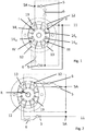
- FIG. 1 is a hydraulic circuit diagram of a double-flow pump to see.
- the two intake regions 13 are connected to a reservoir via suction lines, which are not shown, and suck the fluid from this common reservoir.
- the pressure regions 12 lead to a pressure line 11.
- the vane pump is shown schematically and has four quadrants, the Latin numerals I, II, III, IV are designated. Separated by an approximately horizontal central axis, the pressure regions 12 and the suction regions 13 are arranged diametrically opposite one another. The pressure areas 12 are connected to the pressure side 11 via a line which is shown as a solid line.
- Untererielnuten 14 each extending only along the respective quadrant. They have a radial extent along a radius R about the central axis.
- the Untererielnuten are exemplified as a simple and unstructured grooves uniform size, width formed.
- the Untererielnuten the pressure-side quadrants are connected via throttle bodies 6 with check valves 5 in connection.
- the line On the output side 5A of the check valve, the line is connected to a connection to the underfloor grooves of the suction regions 13. Furthermore, the output side 5A of the check valve communicates with the pressure side 11.
- This circuit describes a pressure-dependent separation of the individual Untererielnuten 14 of Untererielnutenpärchens.
- the vane pump When the vane pump, the blades of the pump fall into the respective sections of the rotor, the pump can be filled with air to a large extent or is operated with cold and therefore highly viscous oil.
- the wings in the first and third quadrant extend by external forces at least a small piece. If gravity is insufficient to extend the wings sufficiently, centrifugal forces or other mechanical measures can cause the wings to extend. Even if this failure of the wings is not sufficient to reach the contour of the cam ring and thus to allow starting of the pumps, so nevertheless increases the volume in the Untererielnuten 14 under the wings. This volume fills up with the oil or the working medium which is present in the openings of the first and third quadrants of the underfloor groove, 14 I , 14 III , to the pressure plate. This suction process over the entire area of the first and third quadrants of the lower wing groove takes place in the lower wing area.
- the entire volume of oil sucked in by the extension of the vanes is conveyed to the second and fourth quadrants of the underflute groove 14 II , 14 IV .
- the two pairs of quadrants, the first and third quadrants I, III and the second and fourth quadrants II, IV are each hydraulically separated from each other.
- the second and fourth quadrant by finding the pressure areas 12, can open to the outside only by a check valve 5. The fact that in these quadrants the wings are pushed by the Hubringkontur, the oil volume, which was sucked in the first and third quadrant, now pushed out again and continuously collected in the second and fourth quadrant of the undercut groove.
- quadrants are possible for the practice of the invention. It is only important that a quadrant pair is separated and a pair of quadrants hydraulically connected. The requirement for the function of the pump is that at least one quadrant pair is arranged hydraulically separated.
- FIG. 2 the construction is slightly different than the construction in FIG. 1 However, the circuits remain the same.
- the check valves 5 in the embodiment of FIG. 2 the pressure connections that connect the pressure areas 12 to the pressure side 11 integrated.
- FIGS. 3 to 5 an exemplary embodiment of a vane pump is shown, in which an integrated solution of the circuit already described is presented.
- the check valve is integrated as a plate valve with little effort in a pressure plate of the vane pump.
- a vane pump is shown in a separate housing as an example in the illustration.
- cartridge pumps whose housings are formed by components of other components such as a motor or a transmission. The terms housing and housing cover thus describe the spatial limit of the vane pump.
- Fig. 3 4 and 5 is shown schematically the structure of a two-stroke vane pump.
- a rotor 32 with extendable wings 30 is shown within a double-stroke cam ring 39.
- the rotor 32 is rotationally driven by a shaft 35 and rotates in a space between a base housing 33 and a pressure plate 31.
- the vane pump includes two pressure areas 12 and two suction areas 13, which by corresponding pressure and suction kidneys and correspondingly enlarging or reducing cells within of the lifting ring are shown.
- the function of such vane pumps is known.
- the cells between two wings increase in the suction region 13 and thus suck fluid into the rotation group.
- the cell volumes between two wings shrink and thus squeeze the fluid out of the pressure regions 12.
- Integrated into the pressure plate 31 are the check valves 5. About connections 36, which are closed with spring plates 8, the working space of the pump with the pressure range 11 is in communication. The spring plate 8 is pressed with a spring 9 against the pressure plate.
- the function of the check valves is such that the pressure ranges are closed when the pump is at a standstill and when the start pressure is established. After the start of the promotion, a target pressure builds up within the rotation group, which allows the non-return valve to be lifted and thus enables a delivery of the pressure oil to the outside into the two pressure channels and thus to corresponding consumers.
- the check valves are designed as simple plate valves. Other variants are possible.
- the pump is operated with a cold start plate, which may also include a check valve according to the invention.
- Cold start plates are installed, in which the check valve 5 can be integrated. Cold start plates are arranged parallel to the pressure plate and perform at standstill a sealing function.
Landscapes
- Engineering & Computer Science (AREA)
- Mechanical Engineering (AREA)
- General Engineering & Computer Science (AREA)
- Rotary Pumps (AREA)
Claims (8)
- Pompe à palettes à double flux, avec un anneau de levage (39), avec un rotor (32), avec des aubes (30), avec un boîtier (33) et avec un couvercle de boîtier, avec des rainures d'aube inférieures (14) pour mettre les faces inférieures des aubes sous pression, dans laquelle les aubes (30) montées de façon déplaçable radialement dans le rotor (32) sont poussées par la pression vers l'extérieur contre l'anneau de levage (39), caractérisée en ce que les rainures d'aube inférieures (14) s'étendent séparément l'une de l'autre le long d'un rayon (R) dans un des quatre quadrants (I, II, III, IV) de la pompe à palettes, dans laquelle la rainure d'aube inférieure (14II, 14IV) du deuxième et du quatrième quadrants, qui sont associés à la région de pression (12) de la pompe à palettes, sont en communication par au moins un clapet anti-retour (5) avec les rainures d'aube inférieures (14I, 14III) des quadrants, qui sont associés au côté d'aspiration (13), dans laquelle dans les deux paires de quadrants, les premier et troisième quadrants (I, III) et les deuxième et quatrième quadrants (II, IV), chaque fois au moins une paire de quadrants est disposée de façon hydrauliquement séparée, du fait qu'il se produit une séparation dépendant de la pression des rainures d'aube inférieures individuelles (14) d'un couple de rainures d'aube inférieures.
- Pompe à palettes à double flux selon la revendication 1, caractérisée en ce que les rainures d'aube inférieures (14I, 14II, 14III, 14IV) ne se recouvrent pas avec les régions d'aspiration ou de pression, mais ne s'étendent respectivement que le long du quadrant respectif et présentent une extension radiale le long d'un rayon autour de l'axe central.
- Pompe à palettes à double flux selon l'une quelconque des revendications précédentes, caractérisée en ce que la communication du quadrant du côté de pression contient au moins un point d'étranglement (6).
- Pompe à palettes à double flux selon la revendication 3, caractérisée en ce que le point d'étranglement respectif (6) est disposé dans la direction d'écoulement avant le clapet anti-retour (5).
- Pompe à palettes selon l'une quelconque des revendications précédentes, caractérisée en ce que les clapets anti-retour (5) ferment à l'arrêt de la pompe les régions de pression (12) vers l'extérieur.
- Pompe à palettes à double flux, caractérisée en ce que les clapets anti-retour (5) sont réalisés sous la forme de soupapes à disque.
- Pompe à palettes à double flux selon l'une quelconque des revendications précédentes, caractérisée en ce que les soupapes à disque sont disposées dans une plaque de pression (31).
- Pompe à palettes à double flux selon l'une quelconque des revendications précédentes, caractérisée en ce que les clapets anti-retour (5) sont disposés sous forme de soupapes à disque dans une plaque de démarrage à froid.
Applications Claiming Priority (1)
| Application Number | Priority Date | Filing Date | Title |
|---|---|---|---|
| DE102014222322.9A DE102014222322B3 (de) | 2014-10-31 | 2014-10-31 | Flügelzellenpumpe mit verbessertem Startverhalten |
Publications (2)
| Publication Number | Publication Date |
|---|---|
| EP3015708A1 EP3015708A1 (fr) | 2016-05-04 |
| EP3015708B1 true EP3015708B1 (fr) | 2018-08-08 |
Family
ID=54288667
Family Applications (1)
| Application Number | Title | Priority Date | Filing Date |
|---|---|---|---|
| EP15188652.0A Active EP3015708B1 (fr) | 2014-10-31 | 2015-10-06 | Pompes a cellules battantes presentant un comportement de demarrage ameliore |
Country Status (2)
| Country | Link |
|---|---|
| EP (1) | EP3015708B1 (fr) |
| DE (1) | DE102014222322B3 (fr) |
Families Citing this family (4)
| Publication number | Priority date | Publication date | Assignee | Title |
|---|---|---|---|---|
| DE102017223530A1 (de) * | 2017-12-21 | 2019-06-27 | Zf Friedrichshafen Ag | Flügelzellenpumpe |
| IT201900009213A1 (it) * | 2019-06-17 | 2020-12-17 | Vhit Spa | Macchina volumetrica |
| DE102019218034B4 (de) * | 2019-11-22 | 2021-07-29 | Hanon Systems Efp Deutschland Gmbh | Mehrflutige Flügelzellenpumpe |
| CN112302853B (zh) * | 2020-09-27 | 2022-10-04 | 秦皇岛雨燕科技开发有限公司 | 一种被动驱动式轴流吸水系统 |
Family Cites Families (6)
| Publication number | Priority date | Publication date | Assignee | Title |
|---|---|---|---|---|
| DE2512433C2 (de) * | 1975-03-21 | 1982-03-04 | Zahnradfabrik Friedrichshafen Ag, 7990 Friedrichshafen | Doppelhubige Drehkolbenpumpe, insbesondere für Hilfskraftlenkungen |
| WO2003056180A1 (fr) * | 2001-12-27 | 2003-07-10 | Luk Fahrzeug-Hydraulik Gmbh & Co. Kg | Pompe |
| DE112006002564B4 (de) * | 2005-10-27 | 2015-09-03 | Magna Powertrain Hückeswagen GmbH | Pumpe |
| DE112009000552A5 (de) * | 2008-04-04 | 2011-04-07 | Ixetic Bad Homburg Gmbh | Pumpe, insbesondere Flügelzellenpumpe |
| WO2012079573A2 (fr) * | 2010-12-15 | 2012-06-21 | Ixetic Bad Homburg Gmbh | Pompe à palettes et procédé permettant de faire fonctionner une pompe à palettes |
| EP2773850B1 (fr) * | 2011-11-04 | 2017-03-29 | Continental Automotive GmbH | Dispositif de pompage pour le refoulement d'un fluide |
-
2014
- 2014-10-31 DE DE102014222322.9A patent/DE102014222322B3/de active Active
-
2015
- 2015-10-06 EP EP15188652.0A patent/EP3015708B1/fr active Active
Non-Patent Citations (1)
| Title |
|---|
| None * |
Also Published As
| Publication number | Publication date |
|---|---|
| DE102014222322B3 (de) | 2016-02-04 |
| EP3015708A1 (fr) | 2016-05-04 |
Similar Documents
| Publication | Publication Date | Title |
|---|---|---|
| EP3015708B1 (fr) | Pompes a cellules battantes presentant un comportement de demarrage ameliore | |
| DE102014222321B3 (de) | Flügelzellenpumpe mit verbessertem Startverhalten | |
| DE102016218186A1 (de) | Flügelzellenpumpe, Pumpensystem, Automatikgetriebe und Kraftfahrzeug | |
| WO2012079573A2 (fr) | Pompe à palettes et procédé permettant de faire fonctionner une pompe à palettes | |
| EP2589851A2 (fr) | Pompe de registre | |
| DE102015119095B4 (de) | Kühlmittelpumpe für eine Verbrennungskraftmaschine | |
| DE102016121241A1 (de) | Hydraulischer Antrieb, hydraulischer Motor und integrierte Pumpe mit dem hydraulischen Antrieb | |
| DE2939405A1 (de) | Umlaufende hydraulische vorrichtung | |
| DE10259894A1 (de) | Pumpe | |
| WO1993009349A1 (fr) | Pompe a ailettes | |
| EP1597459B1 (fr) | Ensemble de pompes | |
| DE112016003278T5 (de) | Pumpvorrichtung | |
| DE102020127070A1 (de) | Pumpenaggregat zur Kuppplungsbetätigung | |
| DE102016116756A1 (de) | Fahrzeughydraulikvorrichtung | |
| DE102015217169A1 (de) | Hydrauliksystem für ein Automatikgetriebe | |
| EP2815129A1 (fr) | Système d'étanchéité et pompe équipée d'un système d'étanchéité | |
| DE102016221332A1 (de) | Hydrauliksystem | |
| EP3728851B1 (fr) | Pompe à palettes | |
| DE102013224660A1 (de) | Flügelzellenmaschine mit definiertem Druck in den Hinterflügelräumen | |
| WO2016180570A1 (fr) | Pompe volumétrique, procédé de fonctionnement d'une pompe volumétrique, système de direction et mécanisme | |
| EP3032105A1 (fr) | Pompe à vide mécanique pour véhicule automobile | |
| WO2007048382A1 (fr) | Pompe | |
| EP1948935B1 (fr) | Pompe | |
| DE10037468A1 (de) | Steuerscheibe insbesondere für eine Flügelzellpumpe | |
| WO2017032502A1 (fr) | Pompe et système d'alimentation d'un consommateur |
Legal Events
| Date | Code | Title | Description |
|---|---|---|---|
| PUAI | Public reference made under article 153(3) epc to a published international application that has entered the european phase |
Free format text: ORIGINAL CODE: 0009012 |
|
| AK | Designated contracting states |
Kind code of ref document: A1 Designated state(s): AL AT BE BG CH CY CZ DE DK EE ES FI FR GB GR HR HU IE IS IT LI LT LU LV MC MK MT NL NO PL PT RO RS SE SI SK SM TR |
|
| AX | Request for extension of the european patent |
Extension state: BA ME |
|
| 17P | Request for examination filed |
Effective date: 20160610 |
|
| RBV | Designated contracting states (corrected) |
Designated state(s): AL AT BE BG CH CY CZ DE DK EE ES FI FR GB GR HR HU IE IS IT LI LT LU LV MC MK MT NL NO PL PT RO RS SE SI SK SM TR |
|
| RIN1 | Information on inventor provided before grant (corrected) |
Inventor name: BORCHERS, DIRK |
|
| GRAP | Despatch of communication of intention to grant a patent |
Free format text: ORIGINAL CODE: EPIDOSNIGR1 |
|
| INTG | Intention to grant announced |
Effective date: 20180413 |
|
| GRAS | Grant fee paid |
Free format text: ORIGINAL CODE: EPIDOSNIGR3 |
|
| GRAA | (expected) grant |
Free format text: ORIGINAL CODE: 0009210 |
|
| AK | Designated contracting states |
Kind code of ref document: B1 Designated state(s): AL AT BE BG CH CY CZ DE DK EE ES FI FR GB GR HR HU IE IS IT LI LT LU LV MC MK MT NL NO PL PT RO RS SE SI SK SM TR |
|
| REG | Reference to a national code |
Ref country code: GB Ref legal event code: FG4D Free format text: NOT ENGLISH |
|
| REG | Reference to a national code |
Ref country code: CH Ref legal event code: EP Ref country code: AT Ref legal event code: REF Ref document number: 1027331 Country of ref document: AT Kind code of ref document: T Effective date: 20180815 |
|
| REG | Reference to a national code |
Ref country code: IE Ref legal event code: FG4D Free format text: LANGUAGE OF EP DOCUMENT: GERMAN |
|
| REG | Reference to a national code |
Ref country code: DE Ref legal event code: R096 Ref document number: 502015005370 Country of ref document: DE |
|
| REG | Reference to a national code |
Ref country code: FR Ref legal event code: PLFP Year of fee payment: 4 |
|
| REG | Reference to a national code |
Ref country code: NL Ref legal event code: MP Effective date: 20180808 |
|
| REG | Reference to a national code |
Ref country code: LT Ref legal event code: MG4D |
|
| PG25 | Lapsed in a contracting state [announced via postgrant information from national office to epo] |
Ref country code: RS Free format text: LAPSE BECAUSE OF FAILURE TO SUBMIT A TRANSLATION OF THE DESCRIPTION OR TO PAY THE FEE WITHIN THE PRESCRIBED TIME-LIMIT Effective date: 20180808 Ref country code: FI Free format text: LAPSE BECAUSE OF FAILURE TO SUBMIT A TRANSLATION OF THE DESCRIPTION OR TO PAY THE FEE WITHIN THE PRESCRIBED TIME-LIMIT Effective date: 20180808 Ref country code: NO Free format text: LAPSE BECAUSE OF FAILURE TO SUBMIT A TRANSLATION OF THE DESCRIPTION OR TO PAY THE FEE WITHIN THE PRESCRIBED TIME-LIMIT Effective date: 20181108 Ref country code: BG Free format text: LAPSE BECAUSE OF FAILURE TO SUBMIT A TRANSLATION OF THE DESCRIPTION OR TO PAY THE FEE WITHIN THE PRESCRIBED TIME-LIMIT Effective date: 20181108 Ref country code: SE Free format text: LAPSE BECAUSE OF FAILURE TO SUBMIT A TRANSLATION OF THE DESCRIPTION OR TO PAY THE FEE WITHIN THE PRESCRIBED TIME-LIMIT Effective date: 20180808 Ref country code: GR Free format text: LAPSE BECAUSE OF FAILURE TO SUBMIT A TRANSLATION OF THE DESCRIPTION OR TO PAY THE FEE WITHIN THE PRESCRIBED TIME-LIMIT Effective date: 20181109 Ref country code: PL Free format text: LAPSE BECAUSE OF FAILURE TO SUBMIT A TRANSLATION OF THE DESCRIPTION OR TO PAY THE FEE WITHIN THE PRESCRIBED TIME-LIMIT Effective date: 20180808 Ref country code: IS Free format text: LAPSE BECAUSE OF FAILURE TO SUBMIT A TRANSLATION OF THE DESCRIPTION OR TO PAY THE FEE WITHIN THE PRESCRIBED TIME-LIMIT Effective date: 20181208 Ref country code: LT Free format text: LAPSE BECAUSE OF FAILURE TO SUBMIT A TRANSLATION OF THE DESCRIPTION OR TO PAY THE FEE WITHIN THE PRESCRIBED TIME-LIMIT Effective date: 20180808 Ref country code: NL Free format text: LAPSE BECAUSE OF FAILURE TO SUBMIT A TRANSLATION OF THE DESCRIPTION OR TO PAY THE FEE WITHIN THE PRESCRIBED TIME-LIMIT Effective date: 20180808 |
|
| PG25 | Lapsed in a contracting state [announced via postgrant information from national office to epo] |
Ref country code: HR Free format text: LAPSE BECAUSE OF FAILURE TO SUBMIT A TRANSLATION OF THE DESCRIPTION OR TO PAY THE FEE WITHIN THE PRESCRIBED TIME-LIMIT Effective date: 20180808 Ref country code: LV Free format text: LAPSE BECAUSE OF FAILURE TO SUBMIT A TRANSLATION OF THE DESCRIPTION OR TO PAY THE FEE WITHIN THE PRESCRIBED TIME-LIMIT Effective date: 20180808 Ref country code: AL Free format text: LAPSE BECAUSE OF FAILURE TO SUBMIT A TRANSLATION OF THE DESCRIPTION OR TO PAY THE FEE WITHIN THE PRESCRIBED TIME-LIMIT Effective date: 20180808 |
|
| PG25 | Lapsed in a contracting state [announced via postgrant information from national office to epo] |
Ref country code: CZ Free format text: LAPSE BECAUSE OF FAILURE TO SUBMIT A TRANSLATION OF THE DESCRIPTION OR TO PAY THE FEE WITHIN THE PRESCRIBED TIME-LIMIT Effective date: 20180808 Ref country code: RO Free format text: LAPSE BECAUSE OF FAILURE TO SUBMIT A TRANSLATION OF THE DESCRIPTION OR TO PAY THE FEE WITHIN THE PRESCRIBED TIME-LIMIT Effective date: 20180808 Ref country code: ES Free format text: LAPSE BECAUSE OF FAILURE TO SUBMIT A TRANSLATION OF THE DESCRIPTION OR TO PAY THE FEE WITHIN THE PRESCRIBED TIME-LIMIT Effective date: 20180808 Ref country code: EE Free format text: LAPSE BECAUSE OF FAILURE TO SUBMIT A TRANSLATION OF THE DESCRIPTION OR TO PAY THE FEE WITHIN THE PRESCRIBED TIME-LIMIT Effective date: 20180808 Ref country code: IT Free format text: LAPSE BECAUSE OF FAILURE TO SUBMIT A TRANSLATION OF THE DESCRIPTION OR TO PAY THE FEE WITHIN THE PRESCRIBED TIME-LIMIT Effective date: 20180808 |
|
| REG | Reference to a national code |
Ref country code: DE Ref legal event code: R097 Ref document number: 502015005370 Country of ref document: DE |
|
| PG25 | Lapsed in a contracting state [announced via postgrant information from national office to epo] |
Ref country code: DK Free format text: LAPSE BECAUSE OF FAILURE TO SUBMIT A TRANSLATION OF THE DESCRIPTION OR TO PAY THE FEE WITHIN THE PRESCRIBED TIME-LIMIT Effective date: 20180808 Ref country code: SM Free format text: LAPSE BECAUSE OF FAILURE TO SUBMIT A TRANSLATION OF THE DESCRIPTION OR TO PAY THE FEE WITHIN THE PRESCRIBED TIME-LIMIT Effective date: 20180808 Ref country code: SK Free format text: LAPSE BECAUSE OF FAILURE TO SUBMIT A TRANSLATION OF THE DESCRIPTION OR TO PAY THE FEE WITHIN THE PRESCRIBED TIME-LIMIT Effective date: 20180808 |
|
| REG | Reference to a national code |
Ref country code: CH Ref legal event code: PL |
|
| PLBE | No opposition filed within time limit |
Free format text: ORIGINAL CODE: 0009261 |
|
| STAA | Information on the status of an ep patent application or granted ep patent |
Free format text: STATUS: NO OPPOSITION FILED WITHIN TIME LIMIT |
|
| REG | Reference to a national code |
Ref country code: DE Ref legal event code: R082 Ref document number: 502015005370 Country of ref document: DE Representative=s name: HOFFMANN - EITLE PATENT- UND RECHTSANWAELTE PA, DE |
|
| REG | Reference to a national code |
Ref country code: BE Ref legal event code: MM Effective date: 20181031 |
|
| PG25 | Lapsed in a contracting state [announced via postgrant information from national office to epo] |
Ref country code: MC Free format text: LAPSE BECAUSE OF FAILURE TO SUBMIT A TRANSLATION OF THE DESCRIPTION OR TO PAY THE FEE WITHIN THE PRESCRIBED TIME-LIMIT Effective date: 20180808 Ref country code: LU Free format text: LAPSE BECAUSE OF NON-PAYMENT OF DUE FEES Effective date: 20181006 |
|
| 26N | No opposition filed |
Effective date: 20190509 |
|
| REG | Reference to a national code |
Ref country code: IE Ref legal event code: MM4A |
|
| PG25 | Lapsed in a contracting state [announced via postgrant information from national office to epo] |
Ref country code: SI Free format text: LAPSE BECAUSE OF FAILURE TO SUBMIT A TRANSLATION OF THE DESCRIPTION OR TO PAY THE FEE WITHIN THE PRESCRIBED TIME-LIMIT Effective date: 20180808 Ref country code: CH Free format text: LAPSE BECAUSE OF NON-PAYMENT OF DUE FEES Effective date: 20181031 Ref country code: LI Free format text: LAPSE BECAUSE OF NON-PAYMENT OF DUE FEES Effective date: 20181031 Ref country code: BE Free format text: LAPSE BECAUSE OF NON-PAYMENT OF DUE FEES Effective date: 20181031 |
|
| PG25 | Lapsed in a contracting state [announced via postgrant information from national office to epo] |
Ref country code: IE Free format text: LAPSE BECAUSE OF NON-PAYMENT OF DUE FEES Effective date: 20181006 |
|
| PG25 | Lapsed in a contracting state [announced via postgrant information from national office to epo] |
Ref country code: MT Free format text: LAPSE BECAUSE OF FAILURE TO SUBMIT A TRANSLATION OF THE DESCRIPTION OR TO PAY THE FEE WITHIN THE PRESCRIBED TIME-LIMIT Effective date: 20180808 |
|
| REG | Reference to a national code |
Ref country code: DE Ref legal event code: R082 Ref document number: 502015005370 Country of ref document: DE Representative=s name: HOFFMANN - EITLE PATENT- UND RECHTSANWAELTE PA, DE Ref country code: DE Ref legal event code: R081 Ref document number: 502015005370 Country of ref document: DE Owner name: HANON SYSTEMS EFP DEUTSCHLAND GMBH, DE Free format text: FORMER OWNER: MAGNA POWERTRAIN BAD HOMBURG GMBH, 61352 BAD HOMBURG, DE |
|
| PG25 | Lapsed in a contracting state [announced via postgrant information from national office to epo] |
Ref country code: TR Free format text: LAPSE BECAUSE OF FAILURE TO SUBMIT A TRANSLATION OF THE DESCRIPTION OR TO PAY THE FEE WITHIN THE PRESCRIBED TIME-LIMIT Effective date: 20180808 |
|
| PG25 | Lapsed in a contracting state [announced via postgrant information from national office to epo] |
Ref country code: PT Free format text: LAPSE BECAUSE OF FAILURE TO SUBMIT A TRANSLATION OF THE DESCRIPTION OR TO PAY THE FEE WITHIN THE PRESCRIBED TIME-LIMIT Effective date: 20180808 |
|
| PG25 | Lapsed in a contracting state [announced via postgrant information from national office to epo] |
Ref country code: HU Free format text: LAPSE BECAUSE OF FAILURE TO SUBMIT A TRANSLATION OF THE DESCRIPTION OR TO PAY THE FEE WITHIN THE PRESCRIBED TIME-LIMIT; INVALID AB INITIO Effective date: 20151006 Ref country code: CY Free format text: LAPSE BECAUSE OF FAILURE TO SUBMIT A TRANSLATION OF THE DESCRIPTION OR TO PAY THE FEE WITHIN THE PRESCRIBED TIME-LIMIT Effective date: 20180808 Ref country code: MK Free format text: LAPSE BECAUSE OF NON-PAYMENT OF DUE FEES Effective date: 20180808 |
|
| REG | Reference to a national code |
Ref country code: GB Ref legal event code: 732E Free format text: REGISTERED BETWEEN 20200618 AND 20200624 |
|
| REG | Reference to a national code |
Ref country code: AT Ref legal event code: MM01 Ref document number: 1027331 Country of ref document: AT Kind code of ref document: T Effective date: 20201006 |
|
| PG25 | Lapsed in a contracting state [announced via postgrant information from national office to epo] |
Ref country code: AT Free format text: LAPSE BECAUSE OF NON-PAYMENT OF DUE FEES Effective date: 20201006 |
|
| P01 | Opt-out of the competence of the unified patent court (upc) registered |
Effective date: 20230613 |
|
| PGFP | Annual fee paid to national office [announced via postgrant information from national office to epo] |
Ref country code: DE Payment date: 20251021 Year of fee payment: 11 |
|
| PGFP | Annual fee paid to national office [announced via postgrant information from national office to epo] |
Ref country code: GB Payment date: 20251022 Year of fee payment: 11 |
|
| PGFP | Annual fee paid to national office [announced via postgrant information from national office to epo] |
Ref country code: FR Payment date: 20251030 Year of fee payment: 11 |