EP2481983A2 - Ensemble de revêtement de fond arrière générant des turbulences et procédé de refroidissement pour une chambre de combustion de turbine à gaz - Google Patents
Ensemble de revêtement de fond arrière générant des turbulences et procédé de refroidissement pour une chambre de combustion de turbine à gaz Download PDFInfo
- Publication number
- EP2481983A2 EP2481983A2 EP12153500A EP12153500A EP2481983A2 EP 2481983 A2 EP2481983 A2 EP 2481983A2 EP 12153500 A EP12153500 A EP 12153500A EP 12153500 A EP12153500 A EP 12153500A EP 2481983 A2 EP2481983 A2 EP 2481983A2
- Authority
- EP
- European Patent Office
- Prior art keywords
- combustor
- combustor liner
- air
- supports
- cover sleeve
- Prior art date
- Legal status (The legal status is an assumption and is not a legal conclusion. Google has not performed a legal analysis and makes no representation as to the accuracy of the status listed.)
- Granted
Links
Images



Classifications
-
- F—MECHANICAL ENGINEERING; LIGHTING; HEATING; WEAPONS; BLASTING
- F23—COMBUSTION APPARATUS; COMBUSTION PROCESSES
- F23R—GENERATING COMBUSTION PRODUCTS OF HIGH PRESSURE OR HIGH VELOCITY, e.g. GAS-TURBINE COMBUSTION CHAMBERS
- F23R3/00—Continuous combustion chambers using liquid or gaseous fuel
- F23R3/02—Continuous combustion chambers using liquid or gaseous fuel characterised by the air-flow or gas-flow configuration
- F23R3/04—Air inlet arrangements
-
- F—MECHANICAL ENGINEERING; LIGHTING; HEATING; WEAPONS; BLASTING
- F01—MACHINES OR ENGINES IN GENERAL; ENGINE PLANTS IN GENERAL; STEAM ENGINES
- F01D—NON-POSITIVE DISPLACEMENT MACHINES OR ENGINES, e.g. STEAM TURBINES
- F01D9/00—Stators
- F01D9/02—Nozzles; Nozzle boxes; Stator blades; Guide conduits, e.g. individual nozzles
- F01D9/023—Transition ducts between combustor cans and first stage of the turbine in gas-turbine engines; their cooling or sealings
-
- F—MECHANICAL ENGINEERING; LIGHTING; HEATING; WEAPONS; BLASTING
- F23—COMBUSTION APPARATUS; COMBUSTION PROCESSES
- F23D—BURNERS
- F23D14/00—Burners for combustion of a gas, e.g. of a gas stored under pressure as a liquid
- F23D14/46—Details
- F23D14/62—Mixing devices; Mixing tubes
-
- F—MECHANICAL ENGINEERING; LIGHTING; HEATING; WEAPONS; BLASTING
- F23—COMBUSTION APPARATUS; COMBUSTION PROCESSES
- F23R—GENERATING COMBUSTION PRODUCTS OF HIGH PRESSURE OR HIGH VELOCITY, e.g. GAS-TURBINE COMBUSTION CHAMBERS
- F23R3/00—Continuous combustion chambers using liquid or gaseous fuel
- F23R3/005—Combined with pressure or heat exchangers
-
- F—MECHANICAL ENGINEERING; LIGHTING; HEATING; WEAPONS; BLASTING
- F05—INDEXING SCHEMES RELATING TO ENGINES OR PUMPS IN VARIOUS SUBCLASSES OF CLASSES F01-F04
- F05D—INDEXING SCHEME FOR ASPECTS RELATING TO NON-POSITIVE-DISPLACEMENT MACHINES OR ENGINES, GAS-TURBINES OR JET-PROPULSION PLANTS
- F05D2260/00—Function
- F05D2260/20—Heat transfer, e.g. cooling
- F05D2260/221—Improvement of heat transfer
- F05D2260/2214—Improvement of heat transfer by increasing the heat transfer surface
-
- F—MECHANICAL ENGINEERING; LIGHTING; HEATING; WEAPONS; BLASTING
- F05—INDEXING SCHEMES RELATING TO ENGINES OR PUMPS IN VARIOUS SUBCLASSES OF CLASSES F01-F04
- F05D—INDEXING SCHEME FOR ASPECTS RELATING TO NON-POSITIVE-DISPLACEMENT MACHINES OR ENGINES, GAS-TURBINES OR JET-PROPULSION PLANTS
- F05D2260/00—Function
- F05D2260/20—Heat transfer, e.g. cooling
- F05D2260/221—Improvement of heat transfer
- F05D2260/2214—Improvement of heat transfer by increasing the heat transfer surface
- F05D2260/22141—Improvement of heat transfer by increasing the heat transfer surface using fins or ribs
-
- F—MECHANICAL ENGINEERING; LIGHTING; HEATING; WEAPONS; BLASTING
- F23—COMBUSTION APPARATUS; COMBUSTION PROCESSES
- F23R—GENERATING COMBUSTION PRODUCTS OF HIGH PRESSURE OR HIGH VELOCITY, e.g. GAS-TURBINE COMBUSTION CHAMBERS
- F23R2900/00—Special features of, or arrangements for continuous combustion chambers; Combustion processes therefor
- F23R2900/00012—Details of sealing devices
-
- F—MECHANICAL ENGINEERING; LIGHTING; HEATING; WEAPONS; BLASTING
- F23—COMBUSTION APPARATUS; COMBUSTION PROCESSES
- F23R—GENERATING COMBUSTION PRODUCTS OF HIGH PRESSURE OR HIGH VELOCITY, e.g. GAS-TURBINE COMBUSTION CHAMBERS
- F23R2900/00—Special features of, or arrangements for continuous combustion chambers; Combustion processes therefor
- F23R2900/03044—Impingement cooled combustion chamber walls or subassemblies
-
- F—MECHANICAL ENGINEERING; LIGHTING; HEATING; WEAPONS; BLASTING
- F23—COMBUSTION APPARATUS; COMBUSTION PROCESSES
- F23R—GENERATING COMBUSTION PRODUCTS OF HIGH PRESSURE OR HIGH VELOCITY, e.g. GAS-TURBINE COMBUSTION CHAMBERS
- F23R2900/00—Special features of, or arrangements for continuous combustion chambers; Combustion processes therefor
- F23R2900/03045—Convection cooled combustion chamber walls provided with turbolators or means for creating turbulences to increase cooling
Definitions
- This invention relates to internal cooling within a gas turbine engine; and more particularly, to an assembly and method for providing better and more uniform cooling in a transition region between a combustion section and discharge section of the turbine.
- one current practice is to impingement cool the liner, or to provide turbulators on the exterior surface of the liner (see U.S. Pat. No. 7,010,921 ).
- Another practice is to provide an array of concavities on the exterior or outside surface of the liner (see U.S. Pat. No. 6,098,397 ).
- Turbulation works by providing a blunt body in the flow which disrupts the flow creating shear layers and high turbulence to enhance heat transfer on the surface. Dimple concavities function by providing organized vortices that enhance flow mixing and scrub the surface to improve heat transfer.
- the invention resides in a combustor for a turbine comprising: a combustor liner; a first flow sleeve surrounding said combustor liner with a first flow annulus therebetween, said first flow sleeve having a plurality of cooling apertures formed about a circumference thereof for directing compressor discharge air as cooling air into said first flow annulus; a transition piece body connected to said combustor liner, said transition piece body being adapted to carry hot combustion gases to the turbine; a second flow sleeve surrounding said transition piece body, said second flow sleeve having a second plurality of cooling apertures for directing compressor discharge air as cooling air into a second flow annulus between the second flow sleeve and the transition piece body, said first flow annulus connecting to said second flow annulus; a resilient seal structure disposed radially between an aft end portion of said combustor liner and a forward end portion of said transition piece body; and a cover sleeve
- the invention resides in a turbine engine comprising the combustor as described above.
- the invention resides in a method of cooling a transition region between a combustion section comprising a combustor liner and a first flow sleeve surrounding said combustor liner with a first flow annulus therebetween, said first flow sleeve having a plurality of cooling apertures formed about a circumference thereof for directing compressor discharge air as cooling air into said first flow annulus, and a transition region comprising a transition piece body connected to said combustor liner, said transition piece body being adapted to carry hot combustion gases to a turbine, a second flow sleeve surrounding said transition piece body, said second flow sleeve having a second plurality of cooling apertures for directing compressor discharge air as cooling air into a second flow annulus between the second flow sleeve and the transition piece body, said first flow annulus connecting to said second flow annulus; said transition region including a resilient seal structure disposed radially between an aft end portion of said combustor liner and a forward end portion
- FIGURE 1 schematically depicts the aft end of a combustor in cross-section.
- the transition piece 12 includes a radially inner transition piece body 14 and a radially outer transition piece impingement sleeve 16 spaced from the transition piece body 14. Upstream thereof is the combustion liner 18 and the combustor flow sleeve 20 defined in surrounding relation thereto. The encircled region is the transition piece forward sleeve assembly 22.
- Flow from the gas turbine compressor enters into a case 24.
- About 40-60% of the compressor discharge air passes through apertures (not shown in detail) formed along and about the transition piece impingement sleeve 16 for flow in an annular region or annulus 26 between the transition piece body 14 and the radially outer transition piece impingement sleeve 16.
- the remaining compressor discharge flow passes through flow sleeve apertures 28 in the combustion liner cooling sleeve 20 and into an annulus 30 between the cooling sleeve 20 and the liner 18.
- This flow of air mixes with the air from the downstream annulus 26, and it is eventually directed into the fuel injectors inside the combustor liner 18, where it mixes with the gas turbine fuel and is burned.
- FIGURE 1 illustrates the apertures 28 in the combustor flow sleeve 20 as holes. In alternate embodiments, the apertures could have other shapes. For example, the apertures that admit air into the annulus 30 could be slots that extend around the circumference of the combustor flow sleeve 20.
- FIGURE 2 illustrates the connection at 22 between the transition piece 14, 16 and the combustor flow sleeve 18, 20. Specifically, the impingement sleeve 16 (or second flow sleeve) of the transition piece 14 is received in telescoping relationship in a mounting flange 32 on the aft end of the combustor flow sleeve 20 (or first flow sleeve).
- the transition piece 14 also receives the combustor liner 18 in a telescoping relationship.
- the combustor flow sleeve 20 surrounds the combustor liner 18 creating flow annulus 30 (or first flow annulus) therebetween. It can be seen from the flow arrow 34 in FIG. 2 , that crossflow cooling air traveling in annulus 26 continues to flow into annulus 30 in a direction perpendicular to impingement cooling air flowing through the cooling apertures 28 (see flow arrow 36) formed about the circumference of the flow sleeve 20. While three rows of apertures are shown in FIG. 2 , the flow sleeve may have any number of rows of apertures. Also, as noted above, the apertures could be holes, or they could have other shapes, such as circumferential slots.
- a typical can annular reverse-flow combustor is shown for a turbine that is driven by the combustion gases from a fuel where a flowing medium with a high energy content, i.e., the combustion gases, produces a rotary motion as a result of being deflected by rings of blading mounted on a rotor.
- discharge air from the compressor (compressed to a pressure on the order of about 250-400 lb/in 2 ) reverses direction as it passes over the outside of the combustor liners (one shown at 18) and again as it enters the combustor liner 18 en route to the turbine.
- Compressed air and fuel are burned in the combustion chamber, producing gases with a temperature of about 2800°F. These combustion gases flow at a high velocity into turbine section via transition piece 14.
- transition region 22 in FIG. 1 there is a transition region indicated generally at 22 in FIG. 1 between the combustion section and the transition piece.
- the hot gas temperature at the aft end of section 18, the inlet portion of region 22, is on the order of about 2800°F.
- the liner metal temperature at the downstream, outlet portion of region 22 is preferably on the order of 1400 - 1550°F.
- the aft end 50 of the liner defines passage(s) through which cooling air is flowed. The cooling air serves to draw off heat from the liner and thereby significantly lower the liner metal temperature relative to that of the hot gases.
- liner 18 has an associated compression-type seal 38, commonly referred to as a hula seal, mounted between a cover plate 40 of the liner aft end 50, and transition piece 14. More specifically, the cover plate 40 is mounted on the liner aft end 50 to form a mounting surface for the compression seal. As shown in FIGURE 3 , liner 18 has a plurality of axial channels 42 formed with a plurality of axial raised sections or ribs 44 all of which extend over a portion of aft end 50 of the liner 18. The cover plate 40 and ribs 44 together define the respective airflow channels 42. These channels are parallel channels extending over a portion of the aft end of liner 18.
- Cooling air is introduced into the channels through air inlet slots or openings 46 at the forward end of the channels. The air then flows into and through the channels 42 and exits the liner through openings 48. Alternatively, or in addition, cooling air may enter the channels 42 through apertures or holes 47 in the cover plate 40. As shown in FIGURE 4 , the cross-section of the channel as defined by its height may decrease along the length of the channel in an aft direction.
- the invention pertains to the design of a combustor liner used in a gas turbine engine and more specifically the cooled aft-end of the combustor liner as an improvement to the conventional structure shown in FIG. 4 .
- this area has conventionally been composed of axial grooves 42 machined into the liner 18 and a sheet metal cover 40 to support the aft-end Hula seal 38.
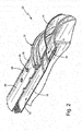
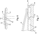
- an annular cooling system is provided that features transverse turbulators 142 as illustrated in FIGURES 5-7 .
- a sheet metal cover 140 is provided to support the aft-end Hula seal 38.
- the cover 140 defines an air passage with the liner aft-end 150.
- the sheet metal cover 140 includes air inlet apertures 146 for passage of cooling media to the region below the Hula seal 38.
- Spaced supports 144 are provided on the aft-end of the combustor liner 150 under the forward and aft ends of the Hula seal 38 to keep the sheet metal cover 140 spaced from the liner aft-end 150.
- each row comprised of a plurality of circumferentially spaced supports 144, as shown in FIGURE 6 .
- Advantages of the illustrated design are many in comparison with the conventional design of FIGURE 4 and include better heat transfer per unit air used, easier production than axial grooves from a machine/manufacturing standpoint; lower heat input to the temperature limited Hula seal; and an ability to achieve a lower temperature in the liner's aft end, which would be critical in engines with higher firing temperatures.
- the transverse turbulators 142 provided according to an example embodiment of the invention are a highly effective heat transfer augmentation device. It is common to see heat transfer numbers of about 200% better than non-turbulated sections with the same quantity of cooling air. Therefore, by providing transverse turbulators 142 as proposed herein, it is possible to achieve the same amount of heat transfer as in the conventional structure with less cooling air. This would be a highly desirable feature in lean pre-mixed gas turbines because the cooling air can be used more effectively in other parts of the system.
- the transverse turbulators are expected to be more manufacturing friendly than the conventional axial channels because, in particular they are less sensitive to small variations in the manufacturing process then channeled flow.
- channels 42 are defined by walls that extend radially outward from the cold side of the liner aft end 50 to the sheet metal cover 40, as shown in FIGURE 4 .
- the cover 40 makes contact with and is supported by the top of the channel defining walls 44 (see U.S. Patent No. 7,010,921 ). A significant amount of heat transfer flows through this assembly and into the Hula seal 38 that sits on top of the sheet metal cover 40.
- the Hula seal's function is to act like a spring while maintaining a good seal. This part has a limited temperature capability and is often very close to its functional limit.
- the configuration proposed herein helps limit the amount of heat transferred to the Hula seal by significantly reducing the contact area through which the heat can flow into the seal by limiting that contact area to the spaced supports 144.
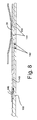
- FIGURE 8 An alternate embodiment is illustrated in FIGURE 8 .
- the Hula seal 38 is rotated 180° from the position it occupied in the embodiment illustrated in FIGURES 5-7 . As a result, only the center arched portion of the seal 38 bears against the top of the cover 140. The ends of the Hula seal 38 would then bear against the forward end of the inner sleeve 14 of the transition piece 12.
- This embodiment only requires two circumferential rows of supports 144 located under the arched center portion of the Hula seal 38. In still other embodiments, only a single circumferential row of supports may be provided under the arched center portion of the Hula seal 38. Because an embodiment as illustrated in FIGURE 8 requires fewer circumferential rows of supports 144, the cost and time required to manufacture the combustor liner 150 can be reduced compared to the embodiment illustrated in FIGURES 5-7 .
Landscapes
- Engineering & Computer Science (AREA)
- Mechanical Engineering (AREA)
- General Engineering & Computer Science (AREA)
- Chemical & Material Sciences (AREA)
- Combustion & Propulsion (AREA)
- Turbine Rotor Nozzle Sealing (AREA)
Applications Claiming Priority (1)
| Application Number | Priority Date | Filing Date | Title |
|---|---|---|---|
| US13/018,886 US8544277B2 (en) | 2007-09-28 | 2011-02-01 | Turbulated aft-end liner assembly and cooling method |
Publications (3)
| Publication Number | Publication Date |
|---|---|
| EP2481983A2 true EP2481983A2 (fr) | 2012-08-01 |
| EP2481983A3 EP2481983A3 (fr) | 2013-05-01 |
| EP2481983B1 EP2481983B1 (fr) | 2018-04-11 |
Family
ID=45558627
Family Applications (1)
| Application Number | Title | Priority Date | Filing Date |
|---|---|---|---|
| EP12153500.9A Active EP2481983B1 (fr) | 2011-02-01 | 2012-02-01 | Ensemble de revêtement de fond arrière générant des turbulences et procédé de refroidissement pour une chambre de combustion de turbine à gaz |
Country Status (3)
| Country | Link |
|---|---|
| US (1) | US8544277B2 (fr) |
| EP (1) | EP2481983B1 (fr) |
| CN (1) | CN102678335B (fr) |
Cited By (1)
| Publication number | Priority date | Publication date | Assignee | Title |
|---|---|---|---|---|
| EP4675174A1 (fr) * | 2024-07-03 | 2026-01-07 | Doosan Enerbility Co., Ltd. | Chambre de combustion et turbine à gaz comprenant celle-ci |
Families Citing this family (27)
| Publication number | Priority date | Publication date | Assignee | Title |
|---|---|---|---|---|
| US8245514B2 (en) * | 2008-07-10 | 2012-08-21 | United Technologies Corporation | Combustion liner for a gas turbine engine including heat transfer columns to increase cooling of a hula seal at the transition duct region |
| US20120304654A1 (en) * | 2011-06-06 | 2012-12-06 | Melton Patrick Benedict | Combustion liner having turbulators |
| US20130086915A1 (en) * | 2011-10-07 | 2013-04-11 | General Electric Company | Film cooled combustion liner assembly |
| US9222672B2 (en) | 2012-08-14 | 2015-12-29 | General Electric Company | Combustor liner cooling assembly |
| US9869279B2 (en) * | 2012-11-02 | 2018-01-16 | General Electric Company | System and method for a multi-wall turbine combustor |
| WO2014179328A1 (fr) * | 2013-04-29 | 2014-11-06 | United Technologies Corporation | Joint pour fermer une fente entre des segments de carter d'une chambre de combustion de moteur à turbine à gaz industriel |
| CN103398398B (zh) * | 2013-08-12 | 2016-01-20 | 北京华清燃气轮机与煤气化联合循环工程技术有限公司 | 一种燃气轮机燃烧室火焰筒与过渡段的双密封连接结构 |
| US9759427B2 (en) * | 2013-11-01 | 2017-09-12 | General Electric Company | Interface assembly for a combustor |
| JP6239938B2 (ja) * | 2013-11-05 | 2017-11-29 | 三菱日立パワーシステムズ株式会社 | ガスタービン燃焼器 |
| EP3002519B1 (fr) * | 2014-09-30 | 2020-05-27 | Ansaldo Energia Switzerland AG | Agencement de chambre de combustion avec système de fixation pour pièces de chambre de combustion |
| EP3073057B1 (fr) * | 2015-03-27 | 2019-05-15 | Ansaldo Energia Switzerland AG | Joint hula d'une turbine à gaz et procédé associé |
| EP3073058B1 (fr) * | 2015-03-27 | 2020-06-10 | Ansaldo Energia Switzerland AG | Agencements d'étanchéité dans des turbines à gaz |
| CN105114981B (zh) * | 2015-09-17 | 2019-02-12 | 中国航空工业集团公司沈阳发动机设计研究所 | 一种燃烧室的密封件 |
| EP3205937B1 (fr) * | 2016-02-09 | 2021-03-31 | Ansaldo Energia IP UK Limited | Agencement de paroi refroidie par impact |
| US10443407B2 (en) | 2016-02-15 | 2019-10-15 | General Electric Company | Accelerator insert for a gas turbine engine airfoil |
| US10215039B2 (en) * | 2016-07-12 | 2019-02-26 | Siemens Energy, Inc. | Ducting arrangement with a ceramic liner for delivering hot-temperature gases in a combustion turbine engine |
| CN107795383B (zh) * | 2016-08-29 | 2019-08-06 | 中国航发商用航空发动机有限责任公司 | 一种燃气轮机冷却气分配系统 |
| KR101986729B1 (ko) * | 2017-08-22 | 2019-06-07 | 두산중공업 주식회사 | 실 영역 집중냉각을 위한 냉각유로 구조 및 이를 포함하는 가스 터빈용 연소기 |
| RU2761262C2 (ru) * | 2017-12-26 | 2021-12-06 | Ансальдо Энергия Свитзерленд Аг | Трубчатая камера сгорания для газовой турбины и газовая турбина, содержащая такую трубчатую камеру сгорания |
| US11306918B2 (en) * | 2018-11-02 | 2022-04-19 | Chromalloy Gas Turbine Llc | Turbulator geometry for a combustion liner |
| EP3874204B1 (fr) * | 2018-11-02 | 2025-12-10 | Chromalloy Gas Turbine LLC | Géométrie de turbulateur pour une chemise de combustion |
| US10982859B2 (en) | 2018-11-02 | 2021-04-20 | Chromalloy Gas Turbine Llc | Cross fire tube retention system |
| US11859818B2 (en) * | 2019-02-25 | 2024-01-02 | General Electric Company | Systems and methods for variable microchannel combustor liner cooling |
| US11255264B2 (en) | 2020-02-25 | 2022-02-22 | General Electric Company | Frame for a heat engine |
| US11560843B2 (en) | 2020-02-25 | 2023-01-24 | General Electric Company | Frame for a heat engine |
| US11326519B2 (en) | 2020-02-25 | 2022-05-10 | General Electric Company | Frame for a heat engine |
| CN112065510B (zh) * | 2020-10-14 | 2025-04-18 | 上海电气集团股份有限公司 | 一种用于燃气轮机透平的水波纹壁冷结构 |
Family Cites Families (20)
| Publication number | Priority date | Publication date | Assignee | Title |
|---|---|---|---|---|
| US4292810A (en) * | 1979-02-01 | 1981-10-06 | Westinghouse Electric Corp. | Gas turbine combustion chamber |
| US4838031A (en) * | 1987-08-06 | 1989-06-13 | Avco Corporation | Internally cooled combustion chamber liner |
| US5024058A (en) * | 1989-12-08 | 1991-06-18 | Sundstrand Corporation | Hot gas generator |
| US5653110A (en) * | 1991-07-22 | 1997-08-05 | General Electric Company | Film cooling of jet engine components |
| US5460002A (en) * | 1993-05-21 | 1995-10-24 | General Electric Company | Catalytically-and aerodynamically-assisted liner for gas turbine combustors |
| US6098397A (en) * | 1998-06-08 | 2000-08-08 | Caterpillar Inc. | Combustor for a low-emissions gas turbine engine |
| WO2003093664A1 (fr) * | 2000-06-28 | 2003-11-13 | Power Systems Mfg. Llc | Refroidissement de chambre de combustion/venturi pour dispositif de combustion a faible emission de nox |
| US6526756B2 (en) * | 2001-02-14 | 2003-03-04 | General Electric Company | Method and apparatus for enhancing heat transfer in a combustor liner for a gas turbine |
| US6772595B2 (en) * | 2002-06-25 | 2004-08-10 | Power Systems Mfg., Llc | Advanced cooling configuration for a low emissions combustor venturi |
| US7284378B2 (en) * | 2004-06-04 | 2007-10-23 | General Electric Company | Methods and apparatus for low emission gas turbine energy generation |
| US7082770B2 (en) * | 2003-12-24 | 2006-08-01 | Martling Vincent C | Flow sleeve for a low NOx combustor |
| US7007482B2 (en) * | 2004-05-28 | 2006-03-07 | Power Systems Mfg., Llc | Combustion liner seal with heat transfer augmentation |
| US7010921B2 (en) * | 2004-06-01 | 2006-03-14 | General Electric Company | Method and apparatus for cooling combustor liner and transition piece of a gas turbine |
| US20060010874A1 (en) * | 2004-07-15 | 2006-01-19 | Intile John C | Cooling aft end of a combustion liner |
| US7386980B2 (en) * | 2005-02-02 | 2008-06-17 | Power Systems Mfg., Llc | Combustion liner with enhanced heat transfer |
| US7681403B2 (en) * | 2006-04-13 | 2010-03-23 | General Electric Company | Forward sleeve retainer plate and method |
| US20090120093A1 (en) * | 2007-09-28 | 2009-05-14 | General Electric Company | Turbulated aft-end liner assembly and cooling method |
| US8245514B2 (en) * | 2008-07-10 | 2012-08-21 | United Technologies Corporation | Combustion liner for a gas turbine engine including heat transfer columns to increase cooling of a hula seal at the transition duct region |
| US20100186415A1 (en) * | 2009-01-23 | 2010-07-29 | General Electric Company | Turbulated aft-end liner assembly and related cooling method |
| US20100223931A1 (en) * | 2009-03-04 | 2010-09-09 | General Electric Company | Pattern cooled combustor liner |
-
2011
- 2011-02-01 US US13/018,886 patent/US8544277B2/en active Active
-
2012
- 2012-02-01 CN CN201210077608.5A patent/CN102678335B/zh active Active
- 2012-02-01 EP EP12153500.9A patent/EP2481983B1/fr active Active
Cited By (1)
| Publication number | Priority date | Publication date | Assignee | Title |
|---|---|---|---|---|
| EP4675174A1 (fr) * | 2024-07-03 | 2026-01-07 | Doosan Enerbility Co., Ltd. | Chambre de combustion et turbine à gaz comprenant celle-ci |
Also Published As
| Publication number | Publication date |
|---|---|
| US8544277B2 (en) | 2013-10-01 |
| CN102678335B (zh) | 2016-05-18 |
| EP2481983B1 (fr) | 2018-04-11 |
| US20110120135A1 (en) | 2011-05-26 |
| EP2481983A3 (fr) | 2013-05-01 |
| CN102678335A (zh) | 2012-09-19 |
Similar Documents
| Publication | Publication Date | Title |
|---|---|---|
| EP2481983B1 (fr) | Ensemble de revêtement de fond arrière générant des turbulences et procédé de refroidissement pour une chambre de combustion de turbine à gaz | |
| US20090120093A1 (en) | Turbulated aft-end liner assembly and cooling method | |
| US7010921B2 (en) | Method and apparatus for cooling combustor liner and transition piece of a gas turbine | |
| EP2211105A2 (fr) | Partie aval d' une chemise de chambre de combustion avec turbulateurs et procédé de refroidissement associé | |
| US9759426B2 (en) | Combustor nozzles in gas turbine engines | |
| EP2378200B1 (fr) | Refroidissement de chemise de chambre de combustion sur une interface de conduite de transition et procédé associé | |
| US10317078B2 (en) | Cooling a multi-walled structure of a turbine engine | |
| EP1413829B1 (fr) | Chambre de combustion avec turbulateurs renversés | |
| US20120304654A1 (en) | Combustion liner having turbulators | |
| US20100223931A1 (en) | Pattern cooled combustor liner | |
| EP3032176B1 (fr) | Guide(s) d'injecteur de carburant pour une chambre de combustion de moteur à turbine | |
| US20170108220A1 (en) | Cooling an aperture body of a combustor wall | |
| EP2375160A2 (fr) | Système de refroidissement de joint en biais | |
| US9134028B2 (en) | Combustor for gas turbine engine | |
| EP3220047A1 (fr) | Montage de manchon de flux de turbine à gaz | |
| US20150059349A1 (en) | Combustor chamber cooling | |
| EP2230456A2 (fr) | Chemise de combustion avec embase d'orifice de mélange | |
| US11262074B2 (en) | HGP component with effusion cooling element having coolant swirling chamber | |
| CN105371303A (zh) | 燃烧器罩盖组件及对应的燃烧器和燃气涡轮机 | |
| CN109416180B (zh) | 用于涡轮发动机中的燃烧器组件及其装配方法 | |
| EP3220048B1 (fr) | Refroidissement d'une chemise de combustion |
Legal Events
| Date | Code | Title | Description |
|---|---|---|---|
| PUAI | Public reference made under article 153(3) epc to a published international application that has entered the european phase |
Free format text: ORIGINAL CODE: 0009012 |
|
| AK | Designated contracting states |
Kind code of ref document: A2 Designated state(s): AL AT BE BG CH CY CZ DE DK EE ES FI FR GB GR HR HU IE IS IT LI LT LU LV MC MK MT NL NO PL PT RO RS SE SI SK SM TR |
|
| AX | Request for extension of the european patent |
Extension state: BA ME |
|
| PUAL | Search report despatched |
Free format text: ORIGINAL CODE: 0009013 |
|
| AK | Designated contracting states |
Kind code of ref document: A3 Designated state(s): AL AT BE BG CH CY CZ DE DK EE ES FI FR GB GR HR HU IE IS IT LI LT LU LV MC MK MT NL NO PL PT RO RS SE SI SK SM TR |
|
| AX | Request for extension of the european patent |
Extension state: BA ME |
|
| RIC1 | Information provided on ipc code assigned before grant |
Ipc: F23R 3/00 20060101ALI20130325BHEP Ipc: F23R 3/60 20060101ALI20130325BHEP Ipc: F23R 3/04 20060101AFI20130325BHEP Ipc: F01D 9/02 20060101ALI20130325BHEP Ipc: F23D 14/62 20060101ALI20130325BHEP |
|
| 17P | Request for examination filed |
Effective date: 20131104 |
|
| RBV | Designated contracting states (corrected) |
Designated state(s): AL AT BE BG CH CY CZ DE DK EE ES FI FR GB GR HR HU IE IS IT LI LT LU LV MC MK MT NL NO PL PT RO RS SE SI SK SM TR |
|
| STAA | Information on the status of an ep patent application or granted ep patent |
Free format text: STATUS: EXAMINATION IS IN PROGRESS |
|
| 17Q | First examination report despatched |
Effective date: 20170223 |
|
| GRAP | Despatch of communication of intention to grant a patent |
Free format text: ORIGINAL CODE: EPIDOSNIGR1 |
|
| STAA | Information on the status of an ep patent application or granted ep patent |
Free format text: STATUS: GRANT OF PATENT IS INTENDED |
|
| INTG | Intention to grant announced |
Effective date: 20171025 |
|
| GRAS | Grant fee paid |
Free format text: ORIGINAL CODE: EPIDOSNIGR3 |
|
| GRAA | (expected) grant |
Free format text: ORIGINAL CODE: 0009210 |
|
| STAA | Information on the status of an ep patent application or granted ep patent |
Free format text: STATUS: THE PATENT HAS BEEN GRANTED |
|
| AK | Designated contracting states |
Kind code of ref document: B1 Designated state(s): AL AT BE BG CH CY CZ DE DK EE ES FI FR GB GR HR HU IE IS IT LI LT LU LV MC MK MT NL NO PL PT RO RS SE SI SK SM TR |
|
| REG | Reference to a national code |
Ref country code: GB Ref legal event code: FG4D |
|
| REG | Reference to a national code |
Ref country code: CH Ref legal event code: EP |
|
| REG | Reference to a national code |
Ref country code: AT Ref legal event code: REF Ref document number: 988443 Country of ref document: AT Kind code of ref document: T Effective date: 20180415 |
|
| REG | Reference to a national code |
Ref country code: IE Ref legal event code: FG4D |
|
| REG | Reference to a national code |
Ref country code: DE Ref legal event code: R096 Ref document number: 602012044950 Country of ref document: DE |
|
| REG | Reference to a national code |
Ref country code: NL Ref legal event code: MP Effective date: 20180411 |
|
| REG | Reference to a national code |
Ref country code: LT Ref legal event code: MG4D |
|
| PG25 | Lapsed in a contracting state [announced via postgrant information from national office to epo] |
Ref country code: NL Free format text: LAPSE BECAUSE OF FAILURE TO SUBMIT A TRANSLATION OF THE DESCRIPTION OR TO PAY THE FEE WITHIN THE PRESCRIBED TIME-LIMIT Effective date: 20180411 |
|
| PG25 | Lapsed in a contracting state [announced via postgrant information from national office to epo] |
Ref country code: PL Free format text: LAPSE BECAUSE OF FAILURE TO SUBMIT A TRANSLATION OF THE DESCRIPTION OR TO PAY THE FEE WITHIN THE PRESCRIBED TIME-LIMIT Effective date: 20180411 Ref country code: NO Free format text: LAPSE BECAUSE OF FAILURE TO SUBMIT A TRANSLATION OF THE DESCRIPTION OR TO PAY THE FEE WITHIN THE PRESCRIBED TIME-LIMIT Effective date: 20180711 Ref country code: ES Free format text: LAPSE BECAUSE OF FAILURE TO SUBMIT A TRANSLATION OF THE DESCRIPTION OR TO PAY THE FEE WITHIN THE PRESCRIBED TIME-LIMIT Effective date: 20180411 Ref country code: LT Free format text: LAPSE BECAUSE OF FAILURE TO SUBMIT A TRANSLATION OF THE DESCRIPTION OR TO PAY THE FEE WITHIN THE PRESCRIBED TIME-LIMIT Effective date: 20180411 Ref country code: AL Free format text: LAPSE BECAUSE OF FAILURE TO SUBMIT A TRANSLATION OF THE DESCRIPTION OR TO PAY THE FEE WITHIN THE PRESCRIBED TIME-LIMIT Effective date: 20180411 Ref country code: BG Free format text: LAPSE BECAUSE OF FAILURE TO SUBMIT A TRANSLATION OF THE DESCRIPTION OR TO PAY THE FEE WITHIN THE PRESCRIBED TIME-LIMIT Effective date: 20180711 Ref country code: SE Free format text: LAPSE BECAUSE OF FAILURE TO SUBMIT A TRANSLATION OF THE DESCRIPTION OR TO PAY THE FEE WITHIN THE PRESCRIBED TIME-LIMIT Effective date: 20180411 Ref country code: FI Free format text: LAPSE BECAUSE OF FAILURE TO SUBMIT A TRANSLATION OF THE DESCRIPTION OR TO PAY THE FEE WITHIN THE PRESCRIBED TIME-LIMIT Effective date: 20180411 |
|
| PG25 | Lapsed in a contracting state [announced via postgrant information from national office to epo] |
Ref country code: LV Free format text: LAPSE BECAUSE OF FAILURE TO SUBMIT A TRANSLATION OF THE DESCRIPTION OR TO PAY THE FEE WITHIN THE PRESCRIBED TIME-LIMIT Effective date: 20180411 Ref country code: RS Free format text: LAPSE BECAUSE OF FAILURE TO SUBMIT A TRANSLATION OF THE DESCRIPTION OR TO PAY THE FEE WITHIN THE PRESCRIBED TIME-LIMIT Effective date: 20180411 Ref country code: HR Free format text: LAPSE BECAUSE OF FAILURE TO SUBMIT A TRANSLATION OF THE DESCRIPTION OR TO PAY THE FEE WITHIN THE PRESCRIBED TIME-LIMIT Effective date: 20180411 Ref country code: GR Free format text: LAPSE BECAUSE OF FAILURE TO SUBMIT A TRANSLATION OF THE DESCRIPTION OR TO PAY THE FEE WITHIN THE PRESCRIBED TIME-LIMIT Effective date: 20180712 |
|
| REG | Reference to a national code |
Ref country code: AT Ref legal event code: MK05 Ref document number: 988443 Country of ref document: AT Kind code of ref document: T Effective date: 20180411 |
|
| PG25 | Lapsed in a contracting state [announced via postgrant information from national office to epo] |
Ref country code: PT Free format text: LAPSE BECAUSE OF FAILURE TO SUBMIT A TRANSLATION OF THE DESCRIPTION OR TO PAY THE FEE WITHIN THE PRESCRIBED TIME-LIMIT Effective date: 20180813 |
|
| REG | Reference to a national code |
Ref country code: DE Ref legal event code: R097 Ref document number: 602012044950 Country of ref document: DE |
|
| PG25 | Lapsed in a contracting state [announced via postgrant information from national office to epo] |
Ref country code: AT Free format text: LAPSE BECAUSE OF FAILURE TO SUBMIT A TRANSLATION OF THE DESCRIPTION OR TO PAY THE FEE WITHIN THE PRESCRIBED TIME-LIMIT Effective date: 20180411 Ref country code: DK Free format text: LAPSE BECAUSE OF FAILURE TO SUBMIT A TRANSLATION OF THE DESCRIPTION OR TO PAY THE FEE WITHIN THE PRESCRIBED TIME-LIMIT Effective date: 20180411 Ref country code: SK Free format text: LAPSE BECAUSE OF FAILURE TO SUBMIT A TRANSLATION OF THE DESCRIPTION OR TO PAY THE FEE WITHIN THE PRESCRIBED TIME-LIMIT Effective date: 20180411 Ref country code: RO Free format text: LAPSE BECAUSE OF FAILURE TO SUBMIT A TRANSLATION OF THE DESCRIPTION OR TO PAY THE FEE WITHIN THE PRESCRIBED TIME-LIMIT Effective date: 20180411 Ref country code: EE Free format text: LAPSE BECAUSE OF FAILURE TO SUBMIT A TRANSLATION OF THE DESCRIPTION OR TO PAY THE FEE WITHIN THE PRESCRIBED TIME-LIMIT Effective date: 20180411 Ref country code: CZ Free format text: LAPSE BECAUSE OF FAILURE TO SUBMIT A TRANSLATION OF THE DESCRIPTION OR TO PAY THE FEE WITHIN THE PRESCRIBED TIME-LIMIT Effective date: 20180411 |
|
| PLBE | No opposition filed within time limit |
Free format text: ORIGINAL CODE: 0009261 |
|
| STAA | Information on the status of an ep patent application or granted ep patent |
Free format text: STATUS: NO OPPOSITION FILED WITHIN TIME LIMIT |
|
| PG25 | Lapsed in a contracting state [announced via postgrant information from national office to epo] |
Ref country code: SM Free format text: LAPSE BECAUSE OF FAILURE TO SUBMIT A TRANSLATION OF THE DESCRIPTION OR TO PAY THE FEE WITHIN THE PRESCRIBED TIME-LIMIT Effective date: 20180411 |
|
| 26N | No opposition filed |
Effective date: 20190114 |
|
| PG25 | Lapsed in a contracting state [announced via postgrant information from national office to epo] |
Ref country code: SI Free format text: LAPSE BECAUSE OF FAILURE TO SUBMIT A TRANSLATION OF THE DESCRIPTION OR TO PAY THE FEE WITHIN THE PRESCRIBED TIME-LIMIT Effective date: 20180411 |
|
| REG | Reference to a national code |
Ref country code: CH Ref legal event code: PL |
|
| GBPC | Gb: european patent ceased through non-payment of renewal fee |
Effective date: 20190201 |
|
| PG25 | Lapsed in a contracting state [announced via postgrant information from national office to epo] |
Ref country code: LU Free format text: LAPSE BECAUSE OF NON-PAYMENT OF DUE FEES Effective date: 20190201 Ref country code: MC Free format text: LAPSE BECAUSE OF FAILURE TO SUBMIT A TRANSLATION OF THE DESCRIPTION OR TO PAY THE FEE WITHIN THE PRESCRIBED TIME-LIMIT Effective date: 20180411 |
|
| REG | Reference to a national code |
Ref country code: BE Ref legal event code: MM Effective date: 20190228 |
|
| REG | Reference to a national code |
Ref country code: IE Ref legal event code: MM4A |
|
| PG25 | Lapsed in a contracting state [announced via postgrant information from national office to epo] |
Ref country code: CH Free format text: LAPSE BECAUSE OF NON-PAYMENT OF DUE FEES Effective date: 20190228 Ref country code: LI Free format text: LAPSE BECAUSE OF NON-PAYMENT OF DUE FEES Effective date: 20190228 |
|
| PG25 | Lapsed in a contracting state [announced via postgrant information from national office to epo] |
Ref country code: IE Free format text: LAPSE BECAUSE OF NON-PAYMENT OF DUE FEES Effective date: 20190201 Ref country code: GB Free format text: LAPSE BECAUSE OF NON-PAYMENT OF DUE FEES Effective date: 20190201 |
|
| PG25 | Lapsed in a contracting state [announced via postgrant information from national office to epo] |
Ref country code: FR Free format text: LAPSE BECAUSE OF NON-PAYMENT OF DUE FEES Effective date: 20190228 Ref country code: BE Free format text: LAPSE BECAUSE OF NON-PAYMENT OF DUE FEES Effective date: 20190228 |
|
| PG25 | Lapsed in a contracting state [announced via postgrant information from national office to epo] |
Ref country code: TR Free format text: LAPSE BECAUSE OF FAILURE TO SUBMIT A TRANSLATION OF THE DESCRIPTION OR TO PAY THE FEE WITHIN THE PRESCRIBED TIME-LIMIT Effective date: 20180411 |
|
| PGFP | Annual fee paid to national office [announced via postgrant information from national office to epo] |
Ref country code: IT Payment date: 20200121 Year of fee payment: 9 |
|
| PG25 | Lapsed in a contracting state [announced via postgrant information from national office to epo] |
Ref country code: MT Free format text: LAPSE BECAUSE OF NON-PAYMENT OF DUE FEES Effective date: 20190201 |
|
| PG25 | Lapsed in a contracting state [announced via postgrant information from national office to epo] |
Ref country code: CY Free format text: LAPSE BECAUSE OF FAILURE TO SUBMIT A TRANSLATION OF THE DESCRIPTION OR TO PAY THE FEE WITHIN THE PRESCRIBED TIME-LIMIT Effective date: 20180411 |
|
| PG25 | Lapsed in a contracting state [announced via postgrant information from national office to epo] |
Ref country code: IS Free format text: LAPSE BECAUSE OF FAILURE TO SUBMIT A TRANSLATION OF THE DESCRIPTION OR TO PAY THE FEE WITHIN THE PRESCRIBED TIME-LIMIT Effective date: 20180811 |
|
| PG25 | Lapsed in a contracting state [announced via postgrant information from national office to epo] |
Ref country code: HU Free format text: LAPSE BECAUSE OF FAILURE TO SUBMIT A TRANSLATION OF THE DESCRIPTION OR TO PAY THE FEE WITHIN THE PRESCRIBED TIME-LIMIT; INVALID AB INITIO Effective date: 20120201 |
|
| PG25 | Lapsed in a contracting state [announced via postgrant information from national office to epo] |
Ref country code: IT Free format text: LAPSE BECAUSE OF NON-PAYMENT OF DUE FEES Effective date: 20210201 |
|
| PG25 | Lapsed in a contracting state [announced via postgrant information from national office to epo] |
Ref country code: MK Free format text: LAPSE BECAUSE OF FAILURE TO SUBMIT A TRANSLATION OF THE DESCRIPTION OR TO PAY THE FEE WITHIN THE PRESCRIBED TIME-LIMIT Effective date: 20180411 |
|
| REG | Reference to a national code |
Ref country code: DE Ref legal event code: R081 Ref document number: 602012044950 Country of ref document: DE Owner name: GENERAL ELECTRIC TECHNOLOGY GMBH, CH Free format text: FORMER OWNER: GENERAL ELECTRIC CO., SCHENECTADY, N.Y., US |
|
| PGFP | Annual fee paid to national office [announced via postgrant information from national office to epo] |
Ref country code: DE Payment date: 20260121 Year of fee payment: 15 |