EP2483477B2 - Dispositif de pontage d'un joint de dilatation - Google Patents
Dispositif de pontage d'un joint de dilatation Download PDFInfo
- Publication number
- EP2483477B2 EP2483477B2 EP10776260.1A EP10776260A EP2483477B2 EP 2483477 B2 EP2483477 B2 EP 2483477B2 EP 10776260 A EP10776260 A EP 10776260A EP 2483477 B2 EP2483477 B2 EP 2483477B2
- Authority
- EP
- European Patent Office
- Prior art keywords
- substructure
- superstructure
- polyurea
- stabilizing
- elastic element
- Prior art date
- Legal status (The legal status is an assumption and is not a legal conclusion. Google has not performed a legal analysis and makes no representation as to the accuracy of the status listed.)
- Active
Links
Images
Classifications
-
- E—FIXED CONSTRUCTIONS
- E01—CONSTRUCTION OF ROADS, RAILWAYS, OR BRIDGES
- E01C—CONSTRUCTION OF, OR SURFACES FOR, ROADS, SPORTS GROUNDS, OR THE LIKE; MACHINES OR AUXILIARY TOOLS FOR CONSTRUCTION OR REPAIR
- E01C11/00—Details of pavings
- E01C11/02—Arrangement or construction of joints; Methods of making joints; Packing for joints
- E01C11/04—Arrangement or construction of joints; Methods of making joints; Packing for joints for cement concrete paving
- E01C11/10—Packing of plastic or elastic materials, e.g. wood, resin
-
- E—FIXED CONSTRUCTIONS
- E01—CONSTRUCTION OF ROADS, RAILWAYS, OR BRIDGES
- E01D—CONSTRUCTION OF BRIDGES, ELEVATED ROADWAYS OR VIADUCTS; ASSEMBLY OF BRIDGES
- E01D19/00—Structural or constructional details of bridges
- E01D19/06—Arrangement, construction or bridging of expansion joints
- E01D19/067—Flat continuous joints cast in situ
-
- E—FIXED CONSTRUCTIONS
- E01—CONSTRUCTION OF ROADS, RAILWAYS, OR BRIDGES
- E01C—CONSTRUCTION OF, OR SURFACES FOR, ROADS, SPORTS GROUNDS, OR THE LIKE; MACHINES OR AUXILIARY TOOLS FOR CONSTRUCTION OR REPAIR
- E01C11/00—Details of pavings
- E01C11/02—Arrangement or construction of joints; Methods of making joints; Packing for joints
- E01C11/04—Arrangement or construction of joints; Methods of making joints; Packing for joints for cement concrete paving
- E01C11/10—Packing of plastic or elastic materials, e.g. wood, resin
- E01C11/103—Joints with packings prepared only in situ; Materials therefor
-
- E—FIXED CONSTRUCTIONS
- E01—CONSTRUCTION OF ROADS, RAILWAYS, OR BRIDGES
- E01D—CONSTRUCTION OF BRIDGES, ELEVATED ROADWAYS OR VIADUCTS; ASSEMBLY OF BRIDGES
- E01D19/00—Structural or constructional details of bridges
- E01D19/06—Arrangement, construction or bridging of expansion joints
Definitions
- the invention relates to a device for bridging an expansion joint in the area of a roadway, comprising a superstructure and a substructure, the superstructure having at least one elastic element and the substructure forming a support for the superstructure.
- connection construction for components undergoing expansion and/or contraction, comprising an elastic connection layer, which is provided with flexible reinforcement means attached to the components.
- the flexible reinforcement means can be formed by at least one spring cast into the connecting layer, the ends of which are mounted on the respective components.
- the spring is in particular a prestressed tension spring.
- a wire mat can be cast into the elastic connecting layer as a flexible reinforcement.
- the elastic connecting layer is formed by an expandable and shrinkable polymerized bitumen.
- the DE 32 25 304 C2 describes an expansion joint cover in roadways with an elastomeric expansion element, which is held watertight in recesses of the joint on both sides delimiting edge bodies made of elastomeric concrete, which are produced at the construction site by casting corresponding recesses in the roadway so that they are flush with the roadway.
- the stretching element consists of an elastomer which corresponds to the elastomeric component of the edge body. This expansion element, produced by casting between the edge bodies, closes the joint between the edge bodies and adheres firmly to them.
- the elastomeric concrete of the edge bodies has mineral grains as an aggregate.
- the elastomer of the expansion element or the elastomeric component of the edge body can be formed by a cold-curing polyurethane.
- the US6561728B1 discloses an expansion joint bridging device having a resilient member cast-in-place from a mixture of polyurethane and bitumen.
- the element can be coated with sand or a blunting material.
- CH 691 496 A5 describes a device for bridging an expansion joint in the area of a roadway, in which a connecting layer bridging the expansion joint is used, which is made of a polymerized bitumen.
- GB 2293396A discloses a roadway transition in which a polyurea-containing resin mortar is used as a grout for anchoring reinforcement structures to the respective substructure.
- AU2002 10047A4 discloses a method for sealing a joint construction in which a joint filling and the adjacent components are sprayed with a sealing layer of polyurea.
- the object of the present invention is to specify an improved device for bridging an expansion joint in the area of a roadway.
- This object is achieved by the device specified in claim 1.
- the expansion joint bridging device according to the invention is characterized—among other features—in particular in that at least one holding element is arranged in the superstructure structure, which is at least partially embedded in the elastic element.
- the connection between the superstructure and the substructure is reinforced in the vertical area of the contact surface between the elastic element of the superstructure and the adjacent road surface, so that this contact surface is relieved and peeling as a result of compressive or tensile stresses is reduced.
- the at least one holding element improves the adhesion of the elastic element to the substructure. Improved mechanical resilience of the device is thus achieved, so that it has a longer service life and maintenance work and the costs associated therewith can be reduced.
- the holding element(s) are formed by an angle profile or angle profiles, legs are present on this holding element or these holding elements, which reach into the elastic element and thus the attachment of the holding element or the holding elements to the elastic Element can be improved, which in turn higher forces can be transmitted.
- the retaining element extends at least approximately over the entire length of the superstructure.
- the holding element extends at least approximately over the entire length of the expansion joint. It won't only the structure of the device itself is simplified - the elastic element is produced on site by casting, as will be explained in more detail below - but a further improvement in the forces that can be absorbed by the expansion joint can be achieved by these forces distributed over a larger area within the elastic element and thus local differences in the load on the holding element or the device do not have an effect or have a reduced effect. Provision can preferably be made for the holding element(s) to have at least one recess into which the elastic element projects. Better embedding of the holding element or the holding elements in the elastic element is thus achieved, which in turn can improve the mechanical stability of the device, in particular against peeling off.
- the elastic element of the superstructure is formed from a castable synthetic resin or plastic, in that it consists at least partially of a polyurea or polyurea system.
- the polyurea or polyurea system has a Shore A hardness of 55 to 85, the tensile strength of the polyurea or polyurea system according to DIN 53504 is between 10 and 30 N/mm2. Furthermore, the polyurea or polyurea system has an elongation according to DIN 53504 between 400 and 1200%.
- the viscosity of the polyurea or polyurea system at 23 °C is between 4000 and 6000 mPas.
- this improves the simple manufacture of the device on the construction site, and on the other hand, unlike with bituminous systems, trafficability is maintained even at high climatic temperatures, for example in direct sunlight, at which bituminous systems already soften.
- a polyurea or polyurea system is more wear-resistant than the bitumen-based systems known in the prior art.
- the use of a polyurea or a polyurea system also better prevents the formation of ruts, crushing and surface leakage.
- the polyurea or polyurea system can be installed cold over a wide temperature range. Conventional bituminous systems have to be installed hot, which involves considerable energy consumption and high noise emissions. Furthermore, larger expansion distances than before can also be mastered, i.e. bridged.
- the layer thickness of the elastic element By using a polyurea or a polyurea system to produce the elastic element, it is possible for the layer thickness of the elastic element to be a maximum of 60 mm. This elastic element is therefore rather thin in contrast to the asphalt expansion joints on the market. This reduction in layer thickness has the advantage that the deformation forces are lower. The deformation forces that occur when the length of the supporting structure changes (tension/compression) cause a load on the adjacent components such as abutments, supporting structures, bridge bearings on the one hand, and internal stresses in the material of the elastic element on the other. The reduced layer thickness of the elastic element therefore allows the adjacent and subsequent components of the structure to be made smaller and more economically.
- the substructure can at least partially consist of a material from the group comprising epoxy resins, polymer concrete, concrete, metals such as steel.
- a substructure structure that can be produced at low cost is thus made available, which provides the necessary rigid properties for supporting the superstructure structure, that is to say in particular the elastic element.
- the holding element(s) is/are connected to the substructure with at least one chemical anchor.
- This embodiment variant of the invention further increases the load-bearing capacity of the device in that peeling off in the area of the elastic element can be better prevented by fastening the holding element or the holding elements to the substructure, ie the supporting structure. Furthermore, after the holding element or the holding elements protrude with their upper side into the elastic element and thus also the shear connector or anchors protrude or protrude with one end into the elastic element, a better composite effect is achieved, which leads to removal the compressive and tensile stresses occurring on the adhesive surface between the superstructure and the substructure.
- At least one sliding lug is formed on the elastic element on an underside pointing in the direction of the substructure, preferably extending continuously over at least approximately the entire length of the superstructure.
- At least one stabilizing element can be arranged in the elastic element. This means that the elastic element can absorb expansion or displacement paths that are significantly larger than those of simple, elastic covering expansion joints made of bituminous materials.
- the stabilizing element or elements can have a sleeve-shaped element or elements, in which the stabilizing element or in which the stabilizing elements are arranged.
- the sleeve-shaped element or elements act as thrust sleeves in which the stabilizing element or elements are guided and in which they can move, thereby improving the effect of the stabilizing elements as reinforcement for the elastic element of the superstructure can be.
- the stabilizing element(s) is/are preferably supported on the holding element or on the holding elements, as a result of which the stabilization of the expansion joint can be improved via these stabilizing elements and the holding elements.
- the stabilizing element(s) extends between the upwardly protruding legs of the angle profiles, i.e. the legs of the angle profiles projecting into the elastic element, and in particular rests against these legs in order to further improve the stabilization function to achieve the interaction of the stabilizing elements with the holding element or the holding elements.
- the stabilizing element(s) or the sleeve-shaped element(s) are at least partially surrounded by a spiral hose. This is cast in particular in the elastic element and causes expansions to be evenly transmitted to the stabilization element or elements. In addition, this reduces or avoids friction with the elastic element, for example the polyurethane casting.
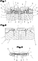
- FIG. 1 shows a device 1 for bridging an expansion joint 2 between a carriageway 3 and an adjoining carriageway 4 of a bridge, in particular a road bridge.
- the device 1 has a superstructure 5 and a substructure 6 .
- the substructure 6 comprises two spaced-apart floor elements 7 , 8 which extend into the area of the expansion joint 2 .
- a substructure sleeper 9, 10 is arranged on each of these floor elements 7, 8, in particular connected to the floor elements 7 and 8, respectively.
- the floor elements 7, 8 can consist, for example, of a concrete such as is used in road construction.
- the two underbody sleepers 9, 10 are arranged between the roadways 3, 4 in the expansion joint 2 and can be made in particular of an epoxy resin or a polymer concrete or another suitable, rigid building material. In particular, it is also possible to produce these two substructure sleepers 9, 10 on site, provided that prefabricated elements are not used for this purpose.
- the substructure 6 is rigid in relation to the superstructure 5 .
- the term “rigid” in the context of the invention means that this substructure 6 or its components, with the exception of thermal expansion or contraction, do not experience any further dimensional changes during operation of the device 1.
- the two underbody sleepers 9, 10 preferably have a width 11, 12 that is dimensioned such that a gap formed by the spaced arrangement of the two floor elements 7, 8 relative to one another is not narrowed, i.e. preferably the end faces of the underbody sleepers 9, 10 that face one another are each arranged flush with the respective end faces of the two floor elements 7, 8 facing one another, as is shown in 1 is shown.
- the superstructure 5 comprises an elastic element 15 which extends between the two roadways 3, 4 and the expansion joint 2 in a bridging manner.
- this elastic element is flush with the surfaces of the roadways 3, 4 on the upper side, so that there is no or no significant elevation or depression in the area of the expansion joint 2 on the roadway side that affects driving comfort.
- the elastic element 15 is supported on the substructure sleepers 9, 10. After the elastic member 15 is cast from a synthetic resin or Plastic is produced directly on the construction site, there is the possibility that the material of the elastic element 15 connects at least in those areas in which this elastic element 15 rests directly on the substructure sleepers 9, 10, forming a contact surface 16.
- a cold-curing, castable synthetic resin or a cold-curing, castable plastic is used for the elastic element 15, namely a polyurea or a polyurea system, in order to be able to produce the elastic element 15 directly on the construction site by casting.
- a polyurea or polyurea system with a hardness adapted to the application is used as the polyurea or polyurea system, so that on the one hand deformation is possible with the lowest possible resistance and on the other hand the loads from traffic result in the lowest possible deformations.
- a 2K polyurea system can be used.
- the polyurea or polyurea system has a Shore A hardness of 55 to 85.
- the tensile strength of the polyurea or polyurea system according to DIN 53504 is between 10 and 30 N/mm2. Furthermore, the polyurea or polyurea system has an elongation according to DIN 53504 between 400 and 1200%. In particular, it is advantageous if a polyurea or a polyurea system with thixotropic properties is used.
- the viscosity of the polyurea or polyurea system is between 4000 and 6000 mPas at 23 °C.
- an adhesion promoter a so-called primer, can also be applied beforehand.
- a cover element 17 is arranged on the substructure sleepers 9, 10, which covers this gap in particular in a moisture-tight manner.
- This cover element 17 can consist of a metal or plastic strip, for example.
- the cover element 17 preferably has a centering element 18 for more precise installation of this cover element 17 or to increase the operational reliability of the device 1, with the centering element 18 protruding into the gap between the two floor elements 7, 8 or the substructure sleepers 9, 10.
- Two holding elements 19, 20 are arranged in the area of the contact surface 16.
- the two holding elements 19, 20 are thus embedded in the elastic element 15, at least on the surface which protrudes in the direction of the latter.
- the holding elements 19, 20 are as angle elements with a base 21, 22 and from the base 21, 22 at least approximately at right angles upwards in the elastic element 15 and embedded in it, protruding legs 23, 24.
- the two legs 23, 24 here, as shown, preferably facing the lanes 3, 4 in each case.
- the holding elements 19, 20 are preferably made of a metal, for example steel.
- the latter can have at least one recess; these are preferably designed as perforated sheet metal or perforated sheet metal, so that during the production of the elastic element 15 from the castable, hardenable synthetic resin or to allow the plastic to enter these recesses.
- the two holding elements 19, 20 extend over the entire length of the expansion joint 2, which extends in the direction of the viewing direction of the embodiment variant 1 extends.
- several individual holding elements 19, 20 are arranged next to one another in the direction of the length.
- only a single holding element 19, which rests on both substructure sleepers 9, 10 and is arranged to bridge the gap is used.
- this single holding element 19 has at least one elastic area, for example in the area of the gap, between the substructure sleepers 9, 10 or the floor elements 7, 8, in order to compensate for the expansion or shrinkage of the device 1 to allow due to the temperature change caused by dimensional changes in the lanes 3, 4 and the road and the bridge.
- this holding element 19 can be designed in several parts with an elastic intermediate piece or there is also the possibility of enabling this expansion or contraction by geometric design of the holding element 19 .
- this holding element 19 can be embodied in a zigzag shape or in the shape of an accordion, etc., in particular in the region of the gap.
- the holding elements 19, 20 can each be provided with at least one shear connector 25, 26, with these shear connectors 25, 26 being made of the elastic element 15 at least in the area of the substructure sleepers 9 or 10, preferably up to the area of the floor elements 7 or 8, as in 1 shown, protrude.
- this shear connector 25, 26 can be held in the substructure sleeper 9, 10 and/or the floor element 7, 8 with a corresponding dowel.
- these chemical anchors 25, 26 are already concreted in with the floor element 7, 8 or cast into the substructure sleepers 9, 10. The embedding of the upper ends of the chemical anchors that protrude into the elastic element 15 takes place in the elastic element 15 during the production of the elastic element 15 from the synthetic resin or the plastic by casting the expansion joint 2.
- shear connector 25, 26 is arranged on each side of the expansion joint 2 is preferably provided within the scope of the invention that in the longitudinal direction of the expansion joint 2 several such shear connectors 25, 26 are arranged side by side and preferably at regular intervals from one another.
- each of these holding elements 19, 20 preferably has its own shear connector 25, 26.
- the chemical anchors 25, 26 are preferably made of a metal, in particular steel.
- the elastic element 15 has at least one sliding lug 27 on both sides of the expansion joint 2, i.e. on each side in the area next to the gap formed between the substructure sleepers 9, 10 or floor elements 7, 8.
- These two thrust lugs 27, 28 are produced during the production of the elastic element 15 by pouring the expansion joint 2 with the synthetic resin or the plastic, for which purpose corresponding groove-like grooves are provided in the substructure sleepers 9, 10 to prevent the synthetic resin from escaping or entering or to allow the plastic in these grooves. It is thus made possible for these thrust lugs 27 , 28 to be produced in one piece with the elastic element 15 .
- the entry of the synthetic resin or plastic into the grooves of the underbody sleepers 9, 10 is made possible by the recesses in the holding elements 19, 20.
- these push lugs 27, 28 in turn extend continuously over the entire length of the expansion joint 2 or the elastic element 15, but there is also the possibility of arranging several such push lugs 27, 28 side by side in the direction of the length of the expansion joint 2.
- the thrust lugs 27, 28 can have a rectangular cross section, viewed in the direction of the length of the expansion joint 2, and the cross sections of the groove-like grooves can also have at least one undercut, whereby a better bond is achieved by the synthetic resin or the plastic fills undercuts.
- the thrust lugs 27, 28 can also have square, polygonal, etc. cross sections.
- an embodiment variant of the device 1 according to the invention is shown.
- This embodiment variant is essentially the same as the device 1 2 that after 1 with the exception that in each case one floor element 7, 8 is formed in one piece with one of the base sleepers 9, 10 in each case.
- these elements of the substructure 6 can be made of structural concrete or the like by casting.
- the elastic element 15 has a layer density 29 ( 1 ) which is a maximum of 60 mm, in particular a maximum of 50 mm.
- FIG. 3 shows a detail of an embodiment variant of the device 1. It is possible within the scope of the invention for at least one stabilizing element 30 to be arranged in the elastic element 15.
- this stabilizing element 30, preferably several such stabilizing elements 30 distributed over the length of the expansion joint 2, can be formed from round steel. Other geometric, rod-shaped shapes are also possible.
- These stabilizing elements 30 reinforce the elastic element 15 and thus improve its mechanical properties.
- the stabilizing element 30 or the stabilizing elements 30 are supported on the holding element or elements 19 , 20 . In particular, the support takes place on the two legs 23, 24 of the holding elements 19, 20, as is shown in 3 is shown.
- Nuts and washers can be arranged on the ends facing the two legs 23, 24 of the holding elements 19, 20 in order to achieve a prestressing of the stabilizing elements 30 between the two legs 23, 24. It is also possible for a compression spring 31, for example a spiral spring, to be fitted over at least some of the stabilizing elements 30 in order to prevent the stabilizing elements from being untied from the casting of the elastic element 15.
- the stabilizing elements 30 are not embedded directly in the elastic element 15, but these stabilizing elements 30 are guided in a sleeve-shaped element 32, which in each case surrounds a stabilizing element 30 in the radial direction.
- stabilizing elements 30 it is possible for several stabilizing elements 30 to be arranged in a sleeve-shaped element 32, but this is not the preferred embodiment variant, since this means that volume for forming the elastic element 15 is lost.
- a spiral hose 33 for example made of plastic, can be provided instead of the sleeve-shaped elements 32 or additionally and surrounding them, which is cast in the elastic element 15 during its manufacture. This also makes it possible to transmit the expansions uniformly to the stabilizing elements 30 .
Landscapes
- Engineering & Computer Science (AREA)
- Architecture (AREA)
- Civil Engineering (AREA)
- Structural Engineering (AREA)
- Road Paving Structures (AREA)
- Bridges Or Land Bridges (AREA)
- Refuge Islands, Traffic Blockers, Or Guard Fence (AREA)
Claims (12)
- Dispositif (1) pour ponter un joint de dilatation (2) dans la zone d'une chaussée, comprenant une construction de superstructure (5) et une construction de sous-structure (6), comportant les caractéristiques suivantes :la construction de sous-structure (6) forme un support pour la construction de superstructure (5) ;la construction de superstructure (5) comporte au moins un élément élastique (15) ;dans la construction de superstructure (5) se trouve au moins un élément de maintien agencé (19, 20), qui est au moins partiellement incorporé dans l'élément élastique (15) ;le au moins un élément de maintien (19, 20) est formé par un profilé angulaire ou par des profilés angulaires et s'étend au moins approximativement sur toute la longueur de la construction de superstructure (5) agencée pour s'étendre en continu ;l'élément élastique (15) de la construction de superstructure (5) est coulé sur place,caractérisé en ce quel'élément élastique (15) est constitué d'une résine synthétique coulable durcissant à froid ou d'une matière plastique coulable durcissant à froid, sous forme de polyurée ou systèmes de polyurée,dans lequel- la polyurée ou le système de polyurée présente une dureté Shore A de 55 à 85,- la résistance à la traction de la polyurée ou du système polyurée selon DIN 53504 est comprise entre 10 et 30 N/mm2,- le système polyurée ou la polyurée a un allongement selon DIN 53504 compris entre 400 et 1200%, et- la viscosité de la polyurée ou du système polyurée à 23°C est comprise entre 4000 et 6000 mPas.
- Dispositif (1) selon la revendication 1, caractérisé en ce que le ou les élément (s) de maintien (19, 20) présente au moins un évidement, dans lequel l'élément élastique (15) dépasse en saillie.
- Dispositif (1) selon une quelconque des revendications 1 ou 2, caractérisé en ce que l'élément élastique (15) présente une épaisseur de la couche (29) de 60mm maximum.
- Dispositif (1) selon une des revendications 1 à 3, caractérisé en ce que la construction de sous-structure (6) est constituée au moins partiellement d'au moins un matériau du groupe constitué par les résines époxy, le béton polymère, le béton et l'acier.
- Dispositif (1) selon une des revendications 1 à 4, caractérisé en ce que le ou les élément(s) de maintien (19, 20) est/sont raccordé(s) par au moins un dispositif d'ancrage composite (25, 26) avec la construction de sous-structure (6).
- Dispositif (1) selon une des revendications 1 à 5, caractérisé en ce que sur l'élément élastique (15) sur une face inférieure orientée en direction de la construction de sous-structure (6), au moins un nez de poussée (27, 28) est réalisé, s'étendant de manière continue, de préférence sur au moins approximativement la totalité de longueur de la superstructure (5).
- Dispositif (1) selon une des revendications 1 à 6, caractérisé en ce qu'au moins un élément stabilisateur (30) est agencé dans l'élément élastique (15).
- Dispositif (1) selon la revendication 7, caractérisé en ce que le ou les éléments stabilisateurs (30) est ou sont disposés dans un ou plusieurs élément (s) en forme de manchon (32).
- Dispositif (1) selon la revendication 7 ou 8, caractérisé en ce que le ou les élément(s) stabilisateur (s) (30) sont supportés sur le ou les élément(s) de maintien (19, 20).
- Dispositif (1) selon une quelconque des revendications 7 à 9, caractérisé en ce que le ou les élément (s) stabilisateur (s) (30) s'étendent entre les branches (23, 24) en saillie vers le haut du profilé angulaires.
- Dispositif (1) selon une quelconque des revendications 7 à 10, caractérisé en ce que le ou les élément (s) stabilisateur(s) (30) présente ou présentent respectivement un ressort de compression (31).
- Dispositif (1) selon une quelconque des revendications 7 à 11, caractérisé en ce que le ou les élément (s) stabilisateur(s) (30) ou le ou les élément(s) en forme de manchon (s) (32) est ou sont entouré (s) au moins partiellement par un flexible spiralé (33).
Applications Claiming Priority (2)
| Application Number | Priority Date | Filing Date | Title |
|---|---|---|---|
| ATA1541/2009A AT508847B1 (de) | 2009-09-30 | 2009-09-30 | Vorrichtung zur überbrückung einer dehnfuge |
| PCT/AT2010/000359 WO2011038434A2 (fr) | 2009-09-30 | 2010-09-30 | Dispositif de pontage d'un joint de dilatation |
Publications (3)
| Publication Number | Publication Date |
|---|---|
| EP2483477A2 EP2483477A2 (fr) | 2012-08-08 |
| EP2483477B1 EP2483477B1 (fr) | 2020-02-19 |
| EP2483477B2 true EP2483477B2 (fr) | 2023-01-18 |
Family
ID=43608358
Family Applications (1)
| Application Number | Title | Priority Date | Filing Date |
|---|---|---|---|
| EP10776260.1A Active EP2483477B2 (fr) | 2009-09-30 | 2010-09-30 | Dispositif de pontage d'un joint de dilatation |
Country Status (8)
| Country | Link |
|---|---|
| US (1) | US8671489B2 (fr) |
| EP (1) | EP2483477B2 (fr) |
| JP (1) | JP6077304B2 (fr) |
| KR (1) | KR20120135399A (fr) |
| AT (1) | AT508847B1 (fr) |
| DK (1) | DK2483477T4 (fr) |
| RU (1) | RU2558557C2 (fr) |
| WO (1) | WO2011038434A2 (fr) |
Families Citing this family (19)
| Publication number | Priority date | Publication date | Assignee | Title |
|---|---|---|---|---|
| CN102561146A (zh) * | 2012-02-10 | 2012-07-11 | 成都市新筑路桥机械股份有限公司 | 一种无缝式弹性体伸缩装置 |
| CN103205922A (zh) * | 2013-05-06 | 2013-07-17 | 成都市新筑路桥机械股份有限公司 | 一种用于无缝式弹性体伸缩装置的稳定元件 |
| ES2534230B1 (es) * | 2013-10-18 | 2015-11-11 | Ingeturarte Sl | Losa de transición entre el estribo y el tablero de un puente con juntas de expansión y contracción de larga vida útil, y métodos de absorción de los movimientos de expansión y contracción del tablero de un puente |
| EP2865822B1 (fr) * | 2013-10-24 | 2017-03-22 | GCP Applied Technologies Inc. | Arrêts d'eau gonflables anti-serpentage |
| CN104034611B (zh) * | 2014-04-18 | 2016-05-11 | 武汉理工大学 | 桥梁无缝伸缩缝材料疲劳开裂模拟测试方法及其测试设备 |
| CN104018425B (zh) * | 2014-06-24 | 2016-10-26 | 宁波路宝科技实业集团有限公司 | 一种快速更换桥梁伸缩缝装置及其安装方法 |
| JP6396770B2 (ja) * | 2014-11-19 | 2018-09-26 | 中日本ハイウェイ・メンテナンス中央株式会社 | 道路床版のジョイント部構造及びその施工方法 |
| ITUB20152883A1 (it) * | 2015-08-05 | 2017-02-05 | Edil Noli Srl | Giunto prefabbricato modulare, particolarmente per pavimentazioni industriali e metodo per la sua produzione |
| RU2596847C1 (ru) * | 2015-09-29 | 2016-09-10 | Федеральное государственное бюджетное образовательное учреждение высшего профессионального образования "Томский государственный архитектурно-строительный университет" (ТГАСУ) | Деформационный шов |
| CN105735121B (zh) * | 2016-04-15 | 2018-02-06 | 山东省建设建工(集团)有限责任公司 | 一种用于桥梁伸缩缝的覆盖机构 |
| US9850626B2 (en) | 2016-05-16 | 2017-12-26 | LTBB Marketing, LLC | Expansion joint seals and methods for manufacturing the same |
| EP3680419B1 (fr) * | 2019-01-14 | 2021-04-21 | MIGUA Fugensysteme GmbH | Dispositif de recouvrement de joint de dilatation |
| JP7103647B2 (ja) * | 2019-02-15 | 2022-07-20 | ライノジャパン株式会社 | 伸縮装置を備えた道路の補修構造、及び補修方法 |
| CN110792035B (zh) * | 2019-11-13 | 2021-05-25 | 成都市新筑路桥机械股份有限公司 | 一种加强型无缝式弹性体伸缩装置及其施工方法 |
| CN110904832B (zh) * | 2019-12-24 | 2024-11-26 | 河南省交通规划设计研究院股份有限公司 | 一种装配式桥梁伸缩缝装置及其施工方法 |
| RU196838U1 (ru) * | 2020-01-10 | 2020-03-17 | Общество с ограниченной ответственностью "ЭластоБетон" | Деформационный шов мостовых сооружений |
| CN112721001B (zh) * | 2021-03-31 | 2021-06-25 | 中国铁道科学研究院集团有限公司铁道建筑研究所 | 一种聚氨酯道床块生产检测成套设备、系统及使用方法 |
| DE102021006143A1 (de) | 2021-12-13 | 2023-06-15 | Mageba Services & Technology Ag | Befahrbares Bauwerk |
| CN115522427B (zh) * | 2022-10-09 | 2024-12-27 | 江苏中路工程技术研究院有限公司 | 一种变形缝伸缩装置、路面结构及其施工方法 |
Citations (9)
| Publication number | Priority date | Publication date | Assignee | Title |
|---|---|---|---|---|
| FR1380667A (fr) † | 1963-10-21 | 1964-12-04 | Teroson Et Prot Chimiqque | Joint de dilatation élastique, coulé, pour ouvrages d'art |
| US3520236A (en) † | 1967-03-03 | 1970-07-14 | Etienne Sequaris | Means for covering and rendering waterproof expansion joints for road bridges and other civil engineering constructions |
| US3822428A (en) † | 1972-07-19 | 1974-07-09 | Stog Kg Ind & Rohrleitung | Joint inserts for bridging expansion joints |
| DE2520791B1 (de) † | 1975-05-09 | 1976-03-18 | Wsw Stahl & Wasserbau Gmbh | Verfahren zum herstellen eines fahrbahnuebergangs fuer dehnungsfugen in bruecken, strassen o.dgl. |
| US4319855A (en) † | 1978-09-28 | 1982-03-16 | Kober Ag | Highway expansion joint |
| JPS59134205A (ja) † | 1983-01-20 | 1984-08-01 | 清水 惣一郎 | 浮き上がり防止装置を有する構造物伸縮継手 |
| GB2293396A (en) † | 1994-09-26 | 1996-03-27 | Btps Services Sa | Joint for joining two elements of a road |
| US5649784A (en) † | 1995-06-16 | 1997-07-22 | Pavetech International, Inc. | Expansion joint system and method of making |
| JP2002348810A (ja) † | 2001-05-23 | 2002-12-04 | Sanyo Kagaku Corp | 埋設ジョイント |
Family Cites Families (33)
| Publication number | Priority date | Publication date | Assignee | Title |
|---|---|---|---|---|
| US1977496A (en) * | 1931-09-28 | 1934-10-16 | Nat Wood Products Co | Floor expansion joint |
| DE1184368B (de) | 1958-10-30 | 1964-12-31 | Rheinstahl Union Brueckenbau | Verfahren zum Vorspannen und Einbauen einer Fugeneinlage fuer Dehnungsfugen in Strassen oder Gehwegen sowie Fugeneinlage zum Durchfuehren des Verfahrens |
| US3880540A (en) * | 1971-03-08 | 1975-04-29 | Brown Co D S | Modular expansion joint |
| GB1318805A (en) * | 1971-10-08 | 1973-05-31 | Invernizzi L | Expansion joints in pre-stressed reinforced concrete bridges |
| US3778954A (en) * | 1972-09-07 | 1973-12-18 | Johns Manville | Method of replacing a damaged bulkhead panel |
| FR2442299A1 (fr) | 1978-11-27 | 1980-06-20 | Freyssinet Int Stup | Joint de revetement de sol, en particulier joint de chaussee |
| ATE13205T1 (de) | 1982-02-12 | 1985-05-15 | Kober Ag | Fugenabdeckung. |
| DE3225304C2 (de) * | 1982-07-07 | 1987-01-15 | Kober Ag, Glarus | Dehnungsfugenabdeckung in Fahrbahnen |
| JPS5952002A (ja) * | 1982-09-17 | 1984-03-26 | 日本奥アンツ−カ株式会社 | 舗装方法 |
| JPS6136402A (ja) | 1984-07-30 | 1986-02-21 | ジャパンコンステック株式会社 | 橋面の連続舗装工法 |
| DE3739717C1 (de) | 1987-11-24 | 1989-03-16 | Kober Ag | Vorrichtung zur UEberbrueckung von Dehnungsfugen |
| FR2661235B1 (fr) * | 1990-04-23 | 1992-07-31 | Traitement Indl Residus Urbains | Poutre formant joint de dilatation entre deux nappes de grilles de foyer accolees, avec des barreaux alternativement fixes et mobiles. |
| DE4114507C2 (de) * | 1991-05-03 | 1997-09-11 | Chemwell Chemie Gmbh | Schalldämmende Überbrückung von Dehnungsfugen |
| JPH0567605U (ja) * | 1992-02-19 | 1993-09-07 | コニシ株式会社 | 道路用伸縮継手 |
| US5297372A (en) * | 1992-06-09 | 1994-03-29 | Pawling Corporation | Elastomeric sealing system for architectural joints |
| FR2717512B1 (fr) | 1994-03-21 | 1996-05-31 | Philippe Chapuis | Joint de chaussée à feuilles. |
| JP2564104B2 (ja) * | 1994-10-21 | 1996-12-18 | 日本伸縮装置工業株式会社 | 道路橋の継手 |
| RU2085648C1 (ru) * | 1995-01-06 | 1997-07-27 | Мелик-Багдасаров Михаил Саркисович | Устройство верхнего строения пути |
| CH691496A5 (de) * | 1996-01-24 | 2001-07-31 | Rsag Reparatur Und Sanierungst | Verbindungskonstruktion für Bauteile. |
| DE19602982C1 (de) * | 1996-01-27 | 1997-01-09 | Migua Fugensysteme Gmbh | Dichtungsvorrichtung für eine Bewegungsfuge |
| US6668412B1 (en) * | 1997-05-29 | 2003-12-30 | Board Of Regents Of University Of Nebraska | Continuous prestressed concrete bridge deck subpanel system |
| JP4272293B2 (ja) * | 1998-03-18 | 2009-06-03 | 北川辺町 | 弾性舗装用常温混合物とそれを用いた弾性舗装体 |
| CA2289495A1 (fr) | 1998-03-18 | 1999-09-23 | Nichireki Co., Ltd. | Composition destine a des paves flexibles utilisable a une temperature ordinaire |
| RU2122063C1 (ru) * | 1998-03-24 | 1998-11-20 | Открытое акционерное общество "Мостотрест" | Деформационный шов |
| FR2777921B1 (fr) * | 1998-04-09 | 2000-09-01 | Rca Corp | Joints de dilatation pour chaussees incorporant des matieres fibreuses |
| FR2792012B1 (fr) * | 1999-04-09 | 2002-06-07 | Freyssinet Int Stup | Procede de realisation d'un joint de chaussee souple, et joint obtenu par un tel procede |
| JP2002054149A (ja) | 2000-08-09 | 2002-02-20 | Mitsui Kinzoku Toryo Kagaku Kk | コンクリート面の隙間被覆構造 |
| RU2186900C2 (ru) * | 2000-11-14 | 2002-08-10 | Общество с ограниченной ответственностью "Мост-инж-сервис" | Деформационный шов железобетонного пролетного строения моста и способ его монтажа |
| AU2002100047A4 (en) | 2002-01-18 | 2002-02-28 | Martin James Dillon | Spray-on joint seal protection |
| JP2004027630A (ja) * | 2002-06-25 | 2004-01-29 | Nippon Steel Composite Co Ltd | 橋梁連結部被覆材用樹脂及び樹脂硬化物 |
| JP4082386B2 (ja) * | 2004-05-27 | 2008-04-30 | アオイテクノサービス株式会社 | コンクリート版用目地構造 |
| US7334963B2 (en) * | 2005-03-08 | 2008-02-26 | Surface Dynamics, Inc. | Concrete slab joint stabilizing system and apparatus |
| US8317444B1 (en) * | 2009-03-24 | 2012-11-27 | Emseal Joint Systems LTD | Movement-compensating plate anchor |
-
2009
- 2009-09-30 AT ATA1541/2009A patent/AT508847B1/de not_active IP Right Cessation
-
2010
- 2010-09-30 US US13/498,932 patent/US8671489B2/en active Active
- 2010-09-30 WO PCT/AT2010/000359 patent/WO2011038434A2/fr not_active Ceased
- 2010-09-30 RU RU2012117168/03A patent/RU2558557C2/ru active IP Right Revival
- 2010-09-30 KR KR1020127011295A patent/KR20120135399A/ko not_active Withdrawn
- 2010-09-30 EP EP10776260.1A patent/EP2483477B2/fr active Active
- 2010-09-30 DK DK10776260.1T patent/DK2483477T4/da active
- 2010-09-30 JP JP2012531181A patent/JP6077304B2/ja active Active
Patent Citations (9)
| Publication number | Priority date | Publication date | Assignee | Title |
|---|---|---|---|---|
| FR1380667A (fr) † | 1963-10-21 | 1964-12-04 | Teroson Et Prot Chimiqque | Joint de dilatation élastique, coulé, pour ouvrages d'art |
| US3520236A (en) † | 1967-03-03 | 1970-07-14 | Etienne Sequaris | Means for covering and rendering waterproof expansion joints for road bridges and other civil engineering constructions |
| US3822428A (en) † | 1972-07-19 | 1974-07-09 | Stog Kg Ind & Rohrleitung | Joint inserts for bridging expansion joints |
| DE2520791B1 (de) † | 1975-05-09 | 1976-03-18 | Wsw Stahl & Wasserbau Gmbh | Verfahren zum herstellen eines fahrbahnuebergangs fuer dehnungsfugen in bruecken, strassen o.dgl. |
| US4319855A (en) † | 1978-09-28 | 1982-03-16 | Kober Ag | Highway expansion joint |
| JPS59134205A (ja) † | 1983-01-20 | 1984-08-01 | 清水 惣一郎 | 浮き上がり防止装置を有する構造物伸縮継手 |
| GB2293396A (en) † | 1994-09-26 | 1996-03-27 | Btps Services Sa | Joint for joining two elements of a road |
| US5649784A (en) † | 1995-06-16 | 1997-07-22 | Pavetech International, Inc. | Expansion joint system and method of making |
| JP2002348810A (ja) † | 2001-05-23 | 2002-12-04 | Sanyo Kagaku Corp | 埋設ジョイント |
Also Published As
| Publication number | Publication date |
|---|---|
| RU2558557C2 (ru) | 2015-08-10 |
| US8671489B2 (en) | 2014-03-18 |
| AT508847B1 (de) | 2012-07-15 |
| WO2011038434A3 (fr) | 2012-06-14 |
| EP2483477A2 (fr) | 2012-08-08 |
| DK2483477T3 (da) | 2020-04-20 |
| RU2012117168A (ru) | 2013-11-10 |
| JP6077304B2 (ja) | 2017-02-08 |
| AT508847A1 (de) | 2011-04-15 |
| US20120308303A1 (en) | 2012-12-06 |
| JP2013506070A (ja) | 2013-02-21 |
| EP2483477B1 (fr) | 2020-02-19 |
| KR20120135399A (ko) | 2012-12-13 |
| WO2011038434A2 (fr) | 2011-04-07 |
| DK2483477T4 (da) | 2023-03-27 |
Similar Documents
| Publication | Publication Date | Title |
|---|---|---|
| EP2483477B2 (fr) | Dispositif de pontage d'un joint de dilatation | |
| EP2877636B1 (fr) | Système de fixation de rail pour zones de raccordement | |
| DE2617341A1 (de) | Fugendichtung fuer strassendecken | |
| DE3736943C1 (de) | Eisenbahnoberbau,insbesondere fuer sehr hohe Fahrgeschwindigkeiten | |
| DE2121981A1 (de) | Verstärkte elastomere Fugendichtung für Brücken und andere Bauwerke | |
| EP2286033B1 (fr) | Système de retenue de véhicule | |
| EP2959060B1 (fr) | Joint de chaussée | |
| DE102004061165A1 (de) | Betonfahrbahn für Schienenfahrzeuge | |
| DE102010037873A1 (de) | Verfahren zum Herstellen eines Stützelementes zum Einbau in Beton- oder Asphaltdecken von Fahrbahn- oder Brückenübergängen sowie damit ausgestatteter Fahrbahn- oder Brückenübergang | |
| DE2951272A1 (de) | Schwelle fuer eine schienenbefestigung | |
| EP2392732B1 (fr) | Système de pontage pour joints de dilatation | |
| EP2940214B1 (fr) | Pont à pièces préfabriquées en forme de segment et segment | |
| WO2005098136A1 (fr) | Superstructure sans ballast pour trafic ferroviaire | |
| EP2447421B1 (fr) | Connection de chaussée à une surface | |
| EP2088240B1 (fr) | Système et procédé de remplissage d'un joint entre un rail et une surface limitrophe | |
| DE2222429A1 (de) | Strassenfugendichtung und Enddammanordnung | |
| EP2800833B1 (fr) | Voie ferrée sans ballast | |
| EP1830002B1 (fr) | Système de support de rails pour voie ferrée | |
| DE20319740U1 (de) | Fahrbahnübergang | |
| AT514682A1 (de) | Eisenbahnschwelle und Anordnung im Oberbau eines Gleises | |
| DE20114116U1 (de) | Körper, insbesondere Schienenfüllkörper bzw. auch Dehn-, Schallschutz- oder Trennstreifen für die Verlegung einer Schiene im Boden, z.B. einer im Straßenbelag verlegten Schiene | |
| DE102008036532A1 (de) | Verfahren zur Herstellung einer Fahrbahn für ein Brückenbauwerk | |
| DE10213100A1 (de) | Maschinenfahrbahn | |
| DE1658446A1 (de) | Dehnungsfugenausbildung fuer einen Verkehrsweg,insbesondere fuer eine Hochstrasse | |
| DE102006048452A1 (de) | Abstützelement zum Einsatz mit Gleisen |
Legal Events
| Date | Code | Title | Description |
|---|---|---|---|
| PUAI | Public reference made under article 153(3) epc to a published international application that has entered the european phase |
Free format text: ORIGINAL CODE: 0009012 |
|
| 17P | Request for examination filed |
Effective date: 20120427 |
|
| AK | Designated contracting states |
Kind code of ref document: A2 Designated state(s): AL AT BE BG CH CY CZ DE DK EE ES FI FR GB GR HR HU IE IS IT LI LT LU LV MC MK MT NL NO PL PT RO SE SI SK SM TR |
|
| RIN1 | Information on inventor provided before grant (corrected) |
Inventor name: GALLAI, GUSTAV Inventor name: DETTER, ERWIN Inventor name: WOLFF, GEORG MICHAEL |
|
| DAX | Request for extension of the european patent (deleted) | ||
| 19U | Interruption of proceedings before grant |
Effective date: 20131025 |
|
| 19W | Proceedings resumed before grant after interruption of proceedings |
Effective date: 20141001 |
|
| RAP1 | Party data changed (applicant data changed or rights of an application transferred) |
Owner name: MAGEBA-SH AG |
|
| STAA | Information on the status of an ep patent application or granted ep patent |
Free format text: STATUS: EXAMINATION IS IN PROGRESS |
|
| 17Q | First examination report despatched |
Effective date: 20170412 |
|
| GRAP | Despatch of communication of intention to grant a patent |
Free format text: ORIGINAL CODE: EPIDOSNIGR1 |
|
| STAA | Information on the status of an ep patent application or granted ep patent |
Free format text: STATUS: GRANT OF PATENT IS INTENDED |
|
| INTG | Intention to grant announced |
Effective date: 20190918 |
|
| GRAS | Grant fee paid |
Free format text: ORIGINAL CODE: EPIDOSNIGR3 |
|
| GRAA | (expected) grant |
Free format text: ORIGINAL CODE: 0009210 |
|
| STAA | Information on the status of an ep patent application or granted ep patent |
Free format text: STATUS: THE PATENT HAS BEEN GRANTED |
|
| AK | Designated contracting states |
Kind code of ref document: B1 Designated state(s): AL AT BE BG CH CY CZ DE DK EE ES FI FR GB GR HR HU IE IS IT LI LT LU LV MC MK MT NL NO PL PT RO SE SI SK SM TR |
|
| REG | Reference to a national code |
Ref country code: GB Ref legal event code: FG4D Free format text: NOT ENGLISH |
|
| REG | Reference to a national code |
Ref country code: CH Ref legal event code: EP |
|
| REG | Reference to a national code |
Ref country code: DE Ref legal event code: R096 Ref document number: 502010016498 Country of ref document: DE |
|
| REG | Reference to a national code |
Ref country code: CH Ref legal event code: NV Representative=s name: GRAETTINGER MOEHRING VON POSCHINGER PATENTANWA, CH |
|
| REG | Reference to a national code |
Ref country code: AT Ref legal event code: REF Ref document number: 1235094 Country of ref document: AT Kind code of ref document: T Effective date: 20200315 |
|
| REG | Reference to a national code |
Ref country code: IE Ref legal event code: FG4D Free format text: LANGUAGE OF EP DOCUMENT: GERMAN |
|
| REG | Reference to a national code |
Ref country code: DK Ref legal event code: T3 Effective date: 20200417 |
|
| REG | Reference to a national code |
Ref country code: NL Ref legal event code: FP |
|
| REG | Reference to a national code |
Ref country code: SE Ref legal event code: TRGR |
|
| PG25 | Lapsed in a contracting state [announced via postgrant information from national office to epo] |
Ref country code: NO Free format text: LAPSE BECAUSE OF FAILURE TO SUBMIT A TRANSLATION OF THE DESCRIPTION OR TO PAY THE FEE WITHIN THE PRESCRIBED TIME-LIMIT Effective date: 20200519 Ref country code: FI Free format text: LAPSE BECAUSE OF FAILURE TO SUBMIT A TRANSLATION OF THE DESCRIPTION OR TO PAY THE FEE WITHIN THE PRESCRIBED TIME-LIMIT Effective date: 20200219 |
|
| REG | Reference to a national code |
Ref country code: LT Ref legal event code: MG4D |
|
| PG25 | Lapsed in a contracting state [announced via postgrant information from national office to epo] |
Ref country code: BG Free format text: LAPSE BECAUSE OF FAILURE TO SUBMIT A TRANSLATION OF THE DESCRIPTION OR TO PAY THE FEE WITHIN THE PRESCRIBED TIME-LIMIT Effective date: 20200519 Ref country code: IS Free format text: LAPSE BECAUSE OF FAILURE TO SUBMIT A TRANSLATION OF THE DESCRIPTION OR TO PAY THE FEE WITHIN THE PRESCRIBED TIME-LIMIT Effective date: 20200619 Ref country code: LV Free format text: LAPSE BECAUSE OF FAILURE TO SUBMIT A TRANSLATION OF THE DESCRIPTION OR TO PAY THE FEE WITHIN THE PRESCRIBED TIME-LIMIT Effective date: 20200219 Ref country code: HR Free format text: LAPSE BECAUSE OF FAILURE TO SUBMIT A TRANSLATION OF THE DESCRIPTION OR TO PAY THE FEE WITHIN THE PRESCRIBED TIME-LIMIT Effective date: 20200219 Ref country code: GR Free format text: LAPSE BECAUSE OF FAILURE TO SUBMIT A TRANSLATION OF THE DESCRIPTION OR TO PAY THE FEE WITHIN THE PRESCRIBED TIME-LIMIT Effective date: 20200520 |
|
| PG25 | Lapsed in a contracting state [announced via postgrant information from national office to epo] |
Ref country code: ES Free format text: LAPSE BECAUSE OF FAILURE TO SUBMIT A TRANSLATION OF THE DESCRIPTION OR TO PAY THE FEE WITHIN THE PRESCRIBED TIME-LIMIT Effective date: 20200219 Ref country code: LT Free format text: LAPSE BECAUSE OF FAILURE TO SUBMIT A TRANSLATION OF THE DESCRIPTION OR TO PAY THE FEE WITHIN THE PRESCRIBED TIME-LIMIT Effective date: 20200219 Ref country code: PT Free format text: LAPSE BECAUSE OF FAILURE TO SUBMIT A TRANSLATION OF THE DESCRIPTION OR TO PAY THE FEE WITHIN THE PRESCRIBED TIME-LIMIT Effective date: 20200712 Ref country code: SK Free format text: LAPSE BECAUSE OF FAILURE TO SUBMIT A TRANSLATION OF THE DESCRIPTION OR TO PAY THE FEE WITHIN THE PRESCRIBED TIME-LIMIT Effective date: 20200219 Ref country code: RO Free format text: LAPSE BECAUSE OF FAILURE TO SUBMIT A TRANSLATION OF THE DESCRIPTION OR TO PAY THE FEE WITHIN THE PRESCRIBED TIME-LIMIT Effective date: 20200219 Ref country code: CZ Free format text: LAPSE BECAUSE OF FAILURE TO SUBMIT A TRANSLATION OF THE DESCRIPTION OR TO PAY THE FEE WITHIN THE PRESCRIBED TIME-LIMIT Effective date: 20200219 Ref country code: SM Free format text: LAPSE BECAUSE OF FAILURE TO SUBMIT A TRANSLATION OF THE DESCRIPTION OR TO PAY THE FEE WITHIN THE PRESCRIBED TIME-LIMIT Effective date: 20200219 Ref country code: EE Free format text: LAPSE BECAUSE OF FAILURE TO SUBMIT A TRANSLATION OF THE DESCRIPTION OR TO PAY THE FEE WITHIN THE PRESCRIBED TIME-LIMIT Effective date: 20200219 |
|
| REG | Reference to a national code |
Ref country code: DE Ref legal event code: R026 Ref document number: 502010016498 Country of ref document: DE |
|
| PLBI | Opposition filed |
Free format text: ORIGINAL CODE: 0009260 |
|
| PLAX | Notice of opposition and request to file observation + time limit sent |
Free format text: ORIGINAL CODE: EPIDOSNOBS2 |
|
| 26 | Opposition filed |
Opponent name: HEBAG AG, UNTERNEHMEN FUER HEBE- UND VERSCHIEBETECHNIK / WALO BERTSCHINGER AG Effective date: 20201112 |
|
| PG25 | Lapsed in a contracting state [announced via postgrant information from national office to epo] |
Ref country code: IT Free format text: LAPSE BECAUSE OF FAILURE TO SUBMIT A TRANSLATION OF THE DESCRIPTION OR TO PAY THE FEE WITHIN THE PRESCRIBED TIME-LIMIT Effective date: 20200219 |
|
| PG25 | Lapsed in a contracting state [announced via postgrant information from national office to epo] |
Ref country code: PL Free format text: LAPSE BECAUSE OF FAILURE TO SUBMIT A TRANSLATION OF THE DESCRIPTION OR TO PAY THE FEE WITHIN THE PRESCRIBED TIME-LIMIT Effective date: 20200219 Ref country code: SI Free format text: LAPSE BECAUSE OF FAILURE TO SUBMIT A TRANSLATION OF THE DESCRIPTION OR TO PAY THE FEE WITHIN THE PRESCRIBED TIME-LIMIT Effective date: 20200219 |
|
| PLBB | Reply of patent proprietor to notice(s) of opposition received |
Free format text: ORIGINAL CODE: EPIDOSNOBS3 |
|
| PG25 | Lapsed in a contracting state [announced via postgrant information from national office to epo] |
Ref country code: MC Free format text: LAPSE BECAUSE OF FAILURE TO SUBMIT A TRANSLATION OF THE DESCRIPTION OR TO PAY THE FEE WITHIN THE PRESCRIBED TIME-LIMIT Effective date: 20200219 |
|
| GBPC | Gb: european patent ceased through non-payment of renewal fee |
Effective date: 20200930 |
|
| PG25 | Lapsed in a contracting state [announced via postgrant information from national office to epo] |
Ref country code: LU Free format text: LAPSE BECAUSE OF NON-PAYMENT OF DUE FEES Effective date: 20200930 |
|
| PG25 | Lapsed in a contracting state [announced via postgrant information from national office to epo] |
Ref country code: FR Free format text: LAPSE BECAUSE OF NON-PAYMENT OF DUE FEES Effective date: 20200930 |
|
| REG | Reference to a national code |
Ref country code: DE Ref legal event code: R081 Ref document number: 502010016498 Country of ref document: DE Owner name: MAGEBA SERVICES & TECHNOLOGY AG, CH Free format text: FORMER OWNER: MAGEBA-SH AG, BUELACH, CH |
|
| PG25 | Lapsed in a contracting state [announced via postgrant information from national office to epo] |
Ref country code: GB Free format text: LAPSE BECAUSE OF NON-PAYMENT OF DUE FEES Effective date: 20200930 Ref country code: IE Free format text: LAPSE BECAUSE OF NON-PAYMENT OF DUE FEES Effective date: 20200930 |
|
| REG | Reference to a national code |
Ref country code: BE Ref legal event code: PD Owner name: MAGEBA SERVICES & TECHNOLOGY AG; CH Free format text: DETAILS ASSIGNMENT: CHANGE OF OWNER(S), ASSIGNMENT; FORMER OWNER NAME: MAGEBA-SH AG Effective date: 20211115 |
|
| PLBP | Opposition withdrawn |
Free format text: ORIGINAL CODE: 0009264 |
|
| PGFP | Annual fee paid to national office [announced via postgrant information from national office to epo] |
Ref country code: DK Payment date: 20220322 Year of fee payment: 12 |
|
| PG25 | Lapsed in a contracting state [announced via postgrant information from national office to epo] |
Ref country code: TR Free format text: LAPSE BECAUSE OF FAILURE TO SUBMIT A TRANSLATION OF THE DESCRIPTION OR TO PAY THE FEE WITHIN THE PRESCRIBED TIME-LIMIT Effective date: 20200219 Ref country code: MT Free format text: LAPSE BECAUSE OF FAILURE TO SUBMIT A TRANSLATION OF THE DESCRIPTION OR TO PAY THE FEE WITHIN THE PRESCRIBED TIME-LIMIT Effective date: 20200219 Ref country code: CY Free format text: LAPSE BECAUSE OF FAILURE TO SUBMIT A TRANSLATION OF THE DESCRIPTION OR TO PAY THE FEE WITHIN THE PRESCRIBED TIME-LIMIT Effective date: 20200219 |
|
| PGFP | Annual fee paid to national office [announced via postgrant information from national office to epo] |
Ref country code: SE Payment date: 20220324 Year of fee payment: 12 |
|
| PG25 | Lapsed in a contracting state [announced via postgrant information from national office to epo] |
Ref country code: MK Free format text: LAPSE BECAUSE OF FAILURE TO SUBMIT A TRANSLATION OF THE DESCRIPTION OR TO PAY THE FEE WITHIN THE PRESCRIBED TIME-LIMIT Effective date: 20200219 Ref country code: AL Free format text: LAPSE BECAUSE OF FAILURE TO SUBMIT A TRANSLATION OF THE DESCRIPTION OR TO PAY THE FEE WITHIN THE PRESCRIBED TIME-LIMIT Effective date: 20200219 |
|
| REG | Reference to a national code |
Ref country code: AT Ref legal event code: PC Ref document number: 1235094 Country of ref document: AT Kind code of ref document: T Owner name: MAGEBA SERVICES & TECHNOLOGY AG, CH Effective date: 20220516 |
|
| REG | Reference to a national code |
Ref country code: NL Ref legal event code: PD Owner name: MAGEBA SERVICES & TECHNOLOGY AG; CH Free format text: DETAILS ASSIGNMENT: CHANGE OF OWNER(S), ASSIGNMENT; FORMER OWNER NAME: MAGEBA-SH AG Effective date: 20220830 |
|
| PUAH | Patent maintained in amended form |
Free format text: ORIGINAL CODE: 0009272 |
|
| STAA | Information on the status of an ep patent application or granted ep patent |
Free format text: STATUS: PATENT MAINTAINED AS AMENDED |
|
| 27A | Patent maintained in amended form |
Effective date: 20230118 |
|
| AK | Designated contracting states |
Kind code of ref document: B2 Designated state(s): AL AT BE BG CH CY CZ DE DK EE ES FI FR GB GR HR HU IE IS IT LI LT LU LV MC MK MT NL NO PL PT RO SE SI SK SM TR |
|
| REG | Reference to a national code |
Ref country code: DE Ref legal event code: R102 Ref document number: 502010016498 Country of ref document: DE |
|
| REG | Reference to a national code |
Ref country code: NL Ref legal event code: FP |
|
| REG | Reference to a national code |
Ref country code: DK Ref legal event code: T4 Effective date: 20230323 |
|
| REG | Reference to a national code |
Ref country code: SE Ref legal event code: RPEO |
|
| REG | Reference to a national code |
Ref country code: DK Ref legal event code: EBP Effective date: 20220930 |
|
| REG | Reference to a national code |
Ref country code: SE Ref legal event code: EUG |
|
| PG25 | Lapsed in a contracting state [announced via postgrant information from national office to epo] |
Ref country code: SE Free format text: LAPSE BECAUSE OF NON-PAYMENT OF DUE FEES Effective date: 20221001 |
|
| PG25 | Lapsed in a contracting state [announced via postgrant information from national office to epo] |
Ref country code: DK Free format text: LAPSE BECAUSE OF NON-PAYMENT OF DUE FEES Effective date: 20220930 |
|
| REG | Reference to a national code |
Ref country code: CH Ref legal event code: U11 Free format text: ST27 STATUS EVENT CODE: U-0-0-U10-U11 (AS PROVIDED BY THE NATIONAL OFFICE) Effective date: 20251001 |
|
| PGFP | Annual fee paid to national office [announced via postgrant information from national office to epo] |
Ref country code: NL Payment date: 20250922 Year of fee payment: 16 |
|
| PGFP | Annual fee paid to national office [announced via postgrant information from national office to epo] |
Ref country code: BE Payment date: 20250919 Year of fee payment: 16 |
|
| PGFP | Annual fee paid to national office [announced via postgrant information from national office to epo] |
Ref country code: AT Payment date: 20250918 Year of fee payment: 16 |
|
| PGFP | Annual fee paid to national office [announced via postgrant information from national office to epo] |
Ref country code: DE Payment date: 20251125 Year of fee payment: 16 |
|
| PGFP | Annual fee paid to national office [announced via postgrant information from national office to epo] |
Ref country code: CH Payment date: 20251001 Year of fee payment: 16 |