EP2484555A1 - Fahrzeugscheinwerfer - Google Patents
Fahrzeugscheinwerfer Download PDFInfo
- Publication number
- EP2484555A1 EP2484555A1 EP12151867A EP12151867A EP2484555A1 EP 2484555 A1 EP2484555 A1 EP 2484555A1 EP 12151867 A EP12151867 A EP 12151867A EP 12151867 A EP12151867 A EP 12151867A EP 2484555 A1 EP2484555 A1 EP 2484555A1
- Authority
- EP
- European Patent Office
- Prior art keywords
- light source
- aiming operation
- operation shaft
- shaft
- lens unit
- Prior art date
- Legal status (The legal status is an assumption and is not a legal conclusion. Google has not performed a legal analysis and makes no representation as to the accuracy of the status listed.)
- Granted
Links
Images


Classifications
-
- B—PERFORMING OPERATIONS; TRANSPORTING
- B60—VEHICLES IN GENERAL
- B60Q—ARRANGEMENT OF SIGNALLING OR LIGHTING DEVICES, THE MOUNTING OR SUPPORTING THEREOF OR CIRCUITS THEREFOR, FOR VEHICLES IN GENERAL
- B60Q1/00—Arrangement of optical signalling or lighting devices, the mounting or supporting thereof or circuits therefor
- B60Q1/02—Arrangement of optical signalling or lighting devices, the mounting or supporting thereof or circuits therefor the devices being primarily intended to illuminate the way ahead or to illuminate other areas of way or environments
- B60Q1/04—Arrangement of optical signalling or lighting devices, the mounting or supporting thereof or circuits therefor the devices being primarily intended to illuminate the way ahead or to illuminate other areas of way or environments the devices being headlights
- B60Q1/06—Arrangement of optical signalling or lighting devices, the mounting or supporting thereof or circuits therefor the devices being primarily intended to illuminate the way ahead or to illuminate other areas of way or environments the devices being headlights adjustable, e.g. remotely-controlled from inside vehicle
- B60Q1/068—Arrangement of optical signalling or lighting devices, the mounting or supporting thereof or circuits therefor the devices being primarily intended to illuminate the way ahead or to illuminate other areas of way or environments the devices being headlights adjustable, e.g. remotely-controlled from inside vehicle by mechanical means
- B60Q1/0683—Adjustable by rotation of a screw
-
- B—PERFORMING OPERATIONS; TRANSPORTING
- B60—VEHICLES IN GENERAL
- B60Q—ARRANGEMENT OF SIGNALLING OR LIGHTING DEVICES, THE MOUNTING OR SUPPORTING THEREOF OR CIRCUITS THEREFOR, FOR VEHICLES IN GENERAL
- B60Q1/00—Arrangement of optical signalling or lighting devices, the mounting or supporting thereof or circuits therefor
- B60Q1/02—Arrangement of optical signalling or lighting devices, the mounting or supporting thereof or circuits therefor the devices being primarily intended to illuminate the way ahead or to illuminate other areas of way or environments
- B60Q1/04—Arrangement of optical signalling or lighting devices, the mounting or supporting thereof or circuits therefor the devices being primarily intended to illuminate the way ahead or to illuminate other areas of way or environments the devices being headlights
- B60Q1/06—Arrangement of optical signalling or lighting devices, the mounting or supporting thereof or circuits therefor the devices being primarily intended to illuminate the way ahead or to illuminate other areas of way or environments the devices being headlights adjustable, e.g. remotely-controlled from inside vehicle
- B60Q1/076—Arrangement of optical signalling or lighting devices, the mounting or supporting thereof or circuits therefor the devices being primarily intended to illuminate the way ahead or to illuminate other areas of way or environments the devices being headlights adjustable, e.g. remotely-controlled from inside vehicle by electrical means including means to transmit the movements, e.g. shafts or joints
-
- F—MECHANICAL ENGINEERING; LIGHTING; HEATING; WEAPONS; BLASTING
- F21—LIGHTING
- F21S—NON-PORTABLE LIGHTING DEVICES; SYSTEMS THEREOF; VEHICLE LIGHTING DEVICES SPECIALLY ADAPTED FOR VEHICLE EXTERIORS
- F21S41/00—Illuminating devices specially adapted for vehicle exteriors, e.g. headlamps
- F21S41/10—Illuminating devices specially adapted for vehicle exteriors, e.g. headlamps characterised by the light source
- F21S41/14—Illuminating devices specially adapted for vehicle exteriors, e.g. headlamps characterised by the light source characterised by the type of light source
- F21S41/141—Light emitting diodes [LED]
- F21S41/147—Light emitting diodes [LED] the main emission direction of the LED being angled to the optical axis of the illuminating device
- F21S41/148—Light emitting diodes [LED] the main emission direction of the LED being angled to the optical axis of the illuminating device the main emission direction of the LED being perpendicular to the optical axis
-
- F—MECHANICAL ENGINEERING; LIGHTING; HEATING; WEAPONS; BLASTING
- F21—LIGHTING
- F21S—NON-PORTABLE LIGHTING DEVICES; SYSTEMS THEREOF; VEHICLE LIGHTING DEVICES SPECIALLY ADAPTED FOR VEHICLE EXTERIORS
- F21S41/00—Illuminating devices specially adapted for vehicle exteriors, e.g. headlamps
- F21S41/10—Illuminating devices specially adapted for vehicle exteriors, e.g. headlamps characterised by the light source
- F21S41/19—Attachment of light sources or lamp holders
-
- F—MECHANICAL ENGINEERING; LIGHTING; HEATING; WEAPONS; BLASTING
- F21—LIGHTING
- F21S—NON-PORTABLE LIGHTING DEVICES; SYSTEMS THEREOF; VEHICLE LIGHTING DEVICES SPECIALLY ADAPTED FOR VEHICLE EXTERIORS
- F21S41/00—Illuminating devices specially adapted for vehicle exteriors, e.g. headlamps
- F21S41/60—Illuminating devices specially adapted for vehicle exteriors, e.g. headlamps characterised by a variable light distribution
- F21S41/63—Illuminating devices specially adapted for vehicle exteriors, e.g. headlamps characterised by a variable light distribution by acting on refractors, filters or transparent cover plates
- F21S41/635—Illuminating devices specially adapted for vehicle exteriors, e.g. headlamps characterised by a variable light distribution by acting on refractors, filters or transparent cover plates by moving refractors, filters or transparent cover plates
-
- F—MECHANICAL ENGINEERING; LIGHTING; HEATING; WEAPONS; BLASTING
- F21—LIGHTING
- F21S—NON-PORTABLE LIGHTING DEVICES; SYSTEMS THEREOF; VEHICLE LIGHTING DEVICES SPECIALLY ADAPTED FOR VEHICLE EXTERIORS
- F21S45/00—Arrangements within vehicle lighting devices specially adapted for vehicle exteriors, for purposes other than emission or distribution of light
- F21S45/40—Cooling of lighting devices
- F21S45/47—Passive cooling, e.g. using fins, thermal conductive elements or openings
- F21S45/48—Passive cooling, e.g. using fins, thermal conductive elements or openings with means for conducting heat from the inside to the outside of the lighting devices, e.g. with fins on the outer surface of the lighting device
Definitions
- the present disclosure relates to a vehicle headlamp. More particularly, the present disclosure relates to a technical field that secures a sealing property in a lamp outer casing and improves a heat-radiation property by fixing a light source unit to a lamp housing while heat sinks are positioned on the outside of a lamp outer casing.
- a vehicle headlamp there is, for example, a vehicle headlamp where a lamp unit is disposed in a lamp outer casing including a lamp housing and a cover.
- the lamp unit includes a lens unit that includes a projection lens projecting light emitted from a light source to the front side and a lens holder holding the projection lens.
- vehicle headlamp there is a vehicle headlamp that includes heat sinks for radiating heat generated during the drive of a light source, that is, the emission of light from a light source (see e.g., JP-A-2008-257959 ).
- a vehicle headlamp is provided with an aiming adjustment mechanism that adjusts the direction of an optical axis at the time of the shipment of the vehicle, the inspection of the vehicle, and the like. Accordingly, when an aiming operation shaft of the aiming adjustment mechanism is rotated about an axis, a lamp unit is rotated in a vertical or lateral direction, and thus the direction of an optical axis is adjusted.
- a lens unit and heat sinks are mounted on a frame disposed in a lamp outer casing and the heat sinks protrude rearward from a protrusion hole formed at a lamp housing.
- An aiming operation shaft is engaged with the frame. Accordingly, the frame, the lens unit, and the heat sinks are tilted integrally with each other by the rotation of the aiming operation shaft, so that the direction of an optical axis is adjusted.
- Exemplary embodiments of the present invention may address the above disadvantages and other disadvantages not described above. However, the present invention is not required to overcome the disadvantages described above, and thus, an exemplary embodiment of the present invention may not overcome any disadvantages.
- One of illustrative aspects of the present invention is to secure a sealing property in a lamp outer casing, and to improve a heat-radiation property.
- a vehicle headlamp comprises: a lamp outer casing; a lamp unit disposed in the lamp uter casing and comprising: a light source unit comprising: a light source that emits light; a light source mounting portion on which the light source is disposed; a reflector that reflects the light emitted from the light source, and a heat sink that radiates heat generated from the light source, a stationary frame that is fixed in the lamp outer casing; a movable frame that is supported by the stationary frame so as to be rotatable about a first rotating shaft extending in a lateral direction or a second rotating shaft extending in a vertical direction, a lens unit that is disposed in the lamp outer casing and supported by the movable frame so as to be movable in the lateral or vertical direction, the lens unit comprising: a projection lens that projects the light emitted from the light source; and a lens holder that holds the projection lens,
- a focal point of the light reflected by the reflector is coincident with a center of the first or second rotating shaft.
- the lens unit is rotated about the first or second rotating shaft such that a distance between the focal point and the projection lens is constant, and the light source unit is fixed to the lamp housing such that the heat sink is positioned on the outside of the lamp outer casing.
- the lamp unit further comprises: a leveling actuator configured to adjust the optical axis and comprising: a main body part mounted on the stationary frame; and a driving part configurd to move relative to the main body part in the longitudinal direction.
- the first or second aiming operation shaft is engaged with the main body part or the driving part, and the first or second aiming operation shaft moves relative to the main body part or the driving part in the longitudinal direction by rotating about an axis.
- the first or second aiming operation shaft used to perform aiming adjustment is also used as the drive shaft used to perform leveling adjustment, it is possible to reduce the size of the vehicle headlamp through the reduction of the number of components.
- the light source unit further comprises a driving circuit that drives the light source.
- the lamp unit further comprises: a connecting member connected to one of the first and second aiming operation shafts, and moving the lens unit relative to the movable frame in the lateral or vertical direction by rotating about an axis, when the first or second aiming operation shaft rotates about an axis.
- the connecting member has an insertion hole at one side thereof.
- the first or second aiming operation shaft is connected to the connecting member. One end portion of the first or second aiming operation shaft is inserted into the insertion hole.
- a diameter of the insertion hole is gradually increased toward the other end of the first or second aiming operation shaft, and the connecting member is rotated integrally with the lens unit relative to the first or second aiming operation shaft when the lens unit is rotated about the rotating shaft as a fulcrum.
- the connecting member is rotated integrally with the lens unit relative to the first or second aiming operation shaft, a load is not applied to the first or second aiming operation shaft during aiming. As a result, it is possible to prevent the deformation or breakage of the first or second aiming operation shaft.
- the light source unit further comprises: a connector positioned behind a central portion of the projection lens so as to supply a drive current to the light source.
- the first or second aiming operation shaft is positioned on the left or right side of a vertical line passing through a center of the projection lens.
- the connector does not interfere with the tool and it is possible to secure the ease of operation when the first or second aiming operation shaft is operated by a tool.
- Vehicle headlamps 1 are disposed and mounted on both left and right end portions of a front end portion of a vehicle body.
- the vehicle headlamp 1 includes a lamp housing 2 and a cover 3.
- the lamp housing 2 includes a recess that is opened to the front side, and the cover 3 closes an opening of the lamp housing 2.
- the lamp housing 2 and the cover 3 form a lamp outer casing 4.
- An inner space of the lamp outer casing 4 is formed as a lamp chamber 5.
- a mounting hole 2a which passes through the lamp housing in a longitudinal direction of a vehicle, is formed at the rear end portion of the lamp housing 2 (see Fig. 2 ).
- Shaft insertion holes 2b and 2c which pass through the lamp housing in the longitudinal direction, are formed at the rear end portion of the lamp housing 2.
- the shaft insertion holes 2b and 2c are positioned on the side of the mounting hole 2a so as to be separated from each other in a vertical direction (see Figs. 1 and 2 ).
- Mounting shaft portions 2d, 2d, ..., which protrude forward, are formed at the lamp housing 2 so as to be separated from each other in the vertical and lateral directions.
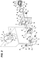
- a lamp unit 6 is disposed in the lamp outer casing 4 (see Figs. 1 and 2 ).
- the lamp unit 6 includes a lens unit 7, a movable frame 8, a stationary frame 9, a first aiming operation shaft 10, a second aiming operation shaft 11, and a light source unit 12 (see Figs. 1 to 3 ).
- the lens unit 7 includes a lens holder 13 and a projection lens 14 that is mounted on the front end portion of the lens holder 13.
- the lens holder 13 includes a holder portion 15 that is formed in a substantially cylindrical shape, a screw shaft 16 that protrudes laterally from the holder portion 15, and supported shafts 17, 17, ... that protrude from the holder portion 15 toward the left and right sides.
- a spiral groove 16a is formed on the outer peripheral surface of the screw shaft 16.
- the supported shafts 17, 17, ... are formed at the holder portion so as to be separated from each other in the vertical and lateral directions.
- a gear 18 is threadedly engaged with the screw shaft 16 of the lens holder 13.
- the gear 18 is a bevel gear, is formed in a substantially annular shape, has a gear portion 18a on one side surface thereof, and has a spiral groove portion 18b on the inner peripheral surface thereof.
- the spiral groove portion 18b of the gear 18 is threadedly engaged with the spiral groove 16a of the screw shaft 16.
- the movable frame 8 includes a supporting frame portion 19 that is formed in the shape of a horizontally long frame, gear supporting protrusions 20 and 20 that protrude forward from the left end portion of the supporting frame portion 19, rotating shafts 21 and 21 that protrude from the supporting frame portion 19 toward the left and right sides, respectively, and a connecting protrusion 22 that protrudes downward from the supporting frame portion 19.
- Shaft supporting recesses 19a, 19a, ... which are opened to the front side and inside so as to be separated from each other in the vertical and lateral directions, are formed at the supporting frame portion 19.
- a member insertion hole 19b which passes through the supporting frame portion in the longitudinal direction, is formed at the left end portion of the supporting frame portion 19.
- the gear supporting protrusions 20 and 20 are formed so as to be separated from each other in the vertical direction, and are positioned above and below the member insertion hole 19b.
- a connecting recess 22a which is opened to the rear side, is formed at the connecting protrusion 22.
- the lens unit 7 is supported by the movable frame 8 so as to be movable in the lateral direction.
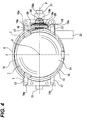
- the supported shafts 17, 17, ... are inserted into the shaft supporting recesses 19a, 19a, ... from the front side, respectively, and the lens unit 7 is supported by the movable frame 8 so that the supported shafts 17, 17, ... are slidable in the shaft supporting recesses 19a, 19a, ..., respectively (see Fig. 4 ).
- the gear 18 is inserted into the gear supporting protrusions 20 and 20 from the front side. Accordingly, the gear 18 is rotatably supported by the gear supporting protrusions 20 and 20 so as not to be movable in the lateral direction.
- first and second pressing members 23 and 24 are mounted on the left and right end portions of the supporting frame portion 19 of the movable frame 8 from the front side, respectively (see Fig. 3 ).
- the first pressing member 23 is mounted on the left end portion of the supporting frame portion 19, so that the gear 18 is closed and the separation of the supported shafts 17 and 17, which are positioned on the left portion of the holder portion, from the shaft supporting recesses 19a and 19a is prevented.
- the second pressing member 24 is mounted on the right end portion of the supporting frame portion 19, so that the separation of the supported shafts 17 and 17, which are positioned on the right portion of the holder portion, from the shaft supporting recesses 19a and 19a is prevented.
- the stationary frame 9 includes a base portion 25, shaft supporting protrusions 26 and 26 that protrude upward from both the left and right end portions of the base portion 25, respectively, and a mounting protrusion 27 that protrudes rearward from the lower end portion of the base 25.
- Shaft supporting recesses 26a and 26a which are respectively opened to the upper side and inside, and insertion holes 26b and 26b, which respectively pass through the upper end portions of the shaft supporting protrusions in the lateral direction, are formed at the upper end portions of the shaft supporting protrusions 26 and 26.
- An arrangement space 27a which is opened to the rear side, is formed at the mounting protrusion 27.
- the base portion 25 is connected to the mounting shaft portions 2d, 2d, ... by, for example, screws or the like, so that the stationary frame 9 is fixed to the lamp housing 2.
- the movable frame 8 is rotatably supported by the stationary frame 9.
- the rotating shafts 21 and 21 are inserted into the shaft supporting recesses 26a and 26a of the shaft supporting protrusions 26 and 26 from the upper side, respectively, and fasteners 28 and 28, which are inserted into the insertion holes 26b and 26b, respectively, are connected to the rotating shafts, so that the movable frame 8 is supported by the stationary frame 9.
- the movable frame 8 can be rotated in a vertical direction relative to the stationary frame 9 about the rotating shafts 21 and 21 as a fulcrum.
- the connecting protrusion 22 of the movable frame 8 is positioned in the arrangement space 27a of the stationary frame 9.
- a leveling actuator 29 is mounted on the stationary frame 9.
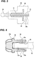
- the leveling actuator 29 includes a main body part 30 and a cylindrical driving part 31 that is moved relative to the main body part 30 in the longitudinal direction (see Figs. 2 and 5 ).
- a spiral groove (not shown) is formed on the inner peripheral surface of the driving part 31.
- the main body part 30 of the leveling actuator 29 is mounted on the rear surface of the mounting protrusion 27 by, for example, screws or the like, and a part of the leveling actuator 29 is disposed in the arrangement space 27a.
- the first aiming operation shaft 10 includes a shaft portion 32 that extends in the longitudinal direction and a rotary operation portion 33 that is connected to the rear end of the shaft portion 32.
- the front end portion of the shaft portion 32 is formed as a rotation preventing portion 32a that is formed in a non-circular shape.
- the shaft portion 32 of the first aiming operation shaft 10 is inserted into the upper shaft insertion hole 2b formed at the lamp housing 2, and the rotation preventing portion 32a is connected to a connecting member 34 (see Fig. 6 ).
- a gear portion 34a is formed at the front end portion of the connecting member 34.
- An insertion hole 35 which is opened to the rear side, is formed at the connecting member 34, and both upper and lower wall surfaces of the wall surfaces of the insertion hole 35 are formed as inclined surfaces 35a and 35a that are inclined so as to be separated from each other toward the rear side. Accordingly, the size of the insertion hole 35 is increased toward the rear side, so that gaps are formed between the rotation preventing portion 32a of the shaft portion 32 and the inclined surfaces 35a and 35a.
- the rotation preventing portion 32a of the first aiming operation shaft 10 When the rotation preventing portion 32a of the first aiming operation shaft 10 is inserted into and connected to the insertion hole 35 of the connecting member 34, the rotation preventing portion 32a is fitted into the insertion hole 35 in the lateral direction. Accordingly, when the first aiming operation shaft 10 is rotated about an axis by the operation of the rotary operation portion 33, the connecting member 34 is rotated integrally with the first aiming operation shaft 10.
- the connecting member 34 is inserted into the member insertion hole 19b of the movable frame 8 from the front side and meshes with the gear 18 of which the gear portion 34a is threadedly engaged with the screw shaft 16 of the lens unit 7 (see Figs. 3 and 4 ). Accordingly, when the connecting member 34 is rotated by the rotation of the first aiming operation shaft 10, the gear 18 is rotated in the direction corresponding to the rotating direction of the first aiming operation shaft 10, the spiral groove 16a of the screw shaft 16 is moved, and the supported shafts 17, 17, ... are guided by the shaft supporting recesses 19a, 19a, ..., respectively, and the lens unit 7 is moved in the lateral direction (the moving lens unit 7 is shown in Fig. 4 by an imaginary line).
- Aiming adjustment in the lateral direction is performed by the lateral movement of the lens unit 7.
- the second aiming operation shaft 11 includes a shaft portion 36 that extends in the longitudinal direction, a rotary operation portion 37 that is connected to the rear end of the shaft portion 36, and a spherical connecting portion 38 that is connected to the front end of the shaft portion 36.
- the front end portion of the shaft portion 36 is formed as a spiral groove portion 36a.
- the shaft portion 36 of the second aiming operation shaft 11 is inserted into the lower shaft insertion hole 2c formed at the lamp housing 2 and the driving part 31 of the leveling actuator 29 (see Fig. 5 ).
- the spiral groove portion 36a is engaged with the spiral groove formed on the inner peripheral surface of the driving part 31.
- the spherical connecting portion 38 is inserted into the connecting recess 22a formed at the connecting protrusion 22, so that the second aiming operation shaft 11 is connected to the movable frame 8.
- the shaft portion 36 of the second aiming operation shaft 11 is inserted into and engaged with the driving part 31 of the leveling actuator 29 has been described above.
- the shaft portion 36 of the second aiming operation shaft 11 may be engaged with the main body part 30 of the leveling actuator 29.
- the spiral groove portion 36a is moved relative to the driving part 31, so that the second aiming operation shaft 11 is moved in the longitudinal direction.
- the movable frame 8 is rotated integrally with the lens unit 7 in the vertical direction relative to the stationary frame 9 about the rotating shafts 21 and 21 as a fulcrum.
- the aiming adjustment in the vertical direction is performed by the rotation of the lens unit 7 in the vertical direction.
- the driving part 31 is moved relative to the main body part 30 in the longitudinal direction by the driving of the leveling actuator 29, the driving part 31 is moved integrally with the second aiming operation shaft 11 in the longitudinal direction. Accordingly, the movable frame 8 is rotated integrally with the lens unit 7 in the vertical direction relative to the stationary frame 9 about the rotating shafts 21 and 21 as a fulcrum.
- Leveling adjustment is performed by the rotation of the lens unit 7 in the vertical direction.
- the second aiming operation shaft 11 used to perform aiming adjustment is used as a drive shaft used to perform leveling adjustment.
- the leveling adjustment mechanism is provided other than the aiming adjustment mechanism.
- the aiming adjustment mechanism may be provided without the leveling adjustment mechanism.
- a member, which has the same spiral groove as the spiral groove of the driving part 31 of the leveling actuator 29, may be mounted on the mounting protrusion 27 of the stationary frame 9, and the spiral groove portion 36a of the second aiming operation shaft 11 may be threadedly engaged with this member.
- the second aiming operation shaft 11 may be disposed using the stationary frame 9 even in a vehicle headlamp that is provided with only the aiming adjustment mechanism. Accordingly, it is possible to share the components of other types of vehicle headlamps and to reduce manufacturing costs.
- the lens unit 7 is rotated integrally with the movable frame 8 about the rotating shafts 21 and 21 as a fulcrum when aiming adjustment is performed in the vertical direction.
- the connecting member 34 is rotated integrally with the lens unit 7 and the movable frame 8 relative to the first aiming operation shaft 10 (the rotating connecting member 34 is shown in Fig. 6 by an imaginary line).
- the light source unit 12 includes a plate-like fixed portion 39 that faces the longitudinal direction, a plate-like light source mounting portion 40 that protrudes forward from the fixed portion 39 and faces the vertical direction, a plurality of heat sinks 41, 41, ... that protrudes rearward from the fixed portion 39, a reflector 42 that is mounted on the light source mounting portion 40, and a light source 43 that is disposed on the light source mounting portion 40.
- An annular fitting portion 39a which protrudes forward, is formed at the fixed portion 39.
- the fitting portion 39a is positioned so as to surround the rear end portion of the light source mounting portion 40.
- a mounting recess 40a which is opened to the upper side and the front side, is formed at the light source mounting portion 40.
- a holding body 44 is mounted on the mounting recess 40a, and the light source 43 is disposed on the light source mounting portion 40 so as to be held by the holding body 44.
- a light-emitting diode (LED) is used as the light source 43.
- the reflector 42 is mounted on the light source mounting portion 40 so as to cover the light source 43 from above.
- the holding body 44 includes a lid 44a.
- a driving circuit 45 for driving the light source 43 is disposed in the holding body 44, and the driving circuit 45 is closed by the lid 44a from above.
- one light source unit 12 includes the driving circuit 45 and the light source 43 driven by the driving circuit 45. Accordingly, it is possible to reduce the manufacturing costs and the size of the vehicle headlamp.
- the holding body 44 for holding the driving circuit 45 or the light source 43 may be formed integrally with the light source mounting portion 40. In this case, it is possible to further reduce the manufacturing costs of the vehicle headlamp through the reduction of the number of components.
- the light source 43 and the driving circuit 45 are mounted on the light source mounting portion 40, a connecting cord for connecting the light source 43 with the driving circuit 45 is not needed. As a result, it is possible to further reduce the manufacturing costs of the vehicle headlamp through the reduction of the number of components.
- the fixed portion 39 of the light source unit 12 is fixed to the rear end portion of the lamp housing 2 from the rear side by, for example, screws or the like so that a packing 46 made of rubber or the like is externally fitted to the fitting portion 39a.
- the light source mounting portion 40 and the reflector 42 are inserted into the mounting hole 2a from the rear side. Accordingly, the light source mounting portion 40, the reflector 42, the light source 43, the holding body 44, and the driving circuit 45 are disposed in the lamp chamber 5.
- the heat sinks 41, 41, ... of the light source unit 12 are positioned on the outside (rear side) of the lamp outer casing 4.
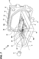
- a focal point F of the light which is emitted from the light source 43 and reflected by the reflector 42, corresponds to the axis P of the rotating shafts 21 and 21 of the movable frame 8 (see Figs. 4 and 7 ). Further, the focal point F is present on an optical axis S, and the optical axis S and the axis P cross each other.
- a connector (not shown) connected to a power circuit (not shown) is connected to the rear end portion of the lamp housing 2, so that power is supplied to the driving circuit 45 from the power circuit through the connector.
- the connector is positioned in the middle of the lamp housing 2 in the lateral direction, and is positioned above or below the mounting hole 2a. Since the connector is positioned in the middle of the lamp housing 2 in the lateral direction, the same lamp housing 2 and the like may be used for left and right vehicle headlamps 1 and 1. As a result, it is possible to share the components of the left and right vehicle headlamps 1 and 1.
- the shaft portion 32 of the first aiming operation shaft 10 and the shaft portion 36 of the second aiming operation shaft 11 are inserted into the shaft insertion holes 2b and 2c formed on the side of the mounting hole 2a, respectively. Accordingly, the first and second aiming operation shafts 10 and 11 are positioned on the side (left or right side) of a vertical line H (see Fig. 4 ) passing through the center of the projection lens 14, and the rotary operation portions 33 and 37 are positioned on the side of the connector that is used to supply power to the driving circuit 45.
- the rotary operation portions 33 and 37 may be operated so as to be rotated from the upper or lower side by a tool such as a screwdriver. Accordingly, if the rotary operation portions 33 and 37 are positioned on the side of the connector as described above, the connector does not interfere with a tool such as a screwdriver during the operation of the rotary operation portions 33 and 37.
- the light source unit 12 is fixed to the lamp housing 2 and the heat sinks 41, 41, ... are positioned on the outside of the lamp outer casing 4.
- the heat sinks 41, 41, ... are not moved together with the lens unit 7 and it is possible to secure a sealing property in the lamp outer casing 4 and to improve a heat-radiation property.
- the heat sinks 41, 41, ... are not present in the lamp outer casing 4, it is possible to reduce the size of the lamp outer casing 4 to the extent of the size the heat sinks. Furthermore, since a heat-radiation property is high, the heat sinks 41, 41, ... may be made small. Therefore, it is possible to reduce the size of the vehicle headlamp 1.
- the lens unit 7 and the light source unit 12 are formed separately from each other in the vehicle headlamp 1, it is possible to replace the light source unit 12 alone separately from the lens unit 7 or to detach/attach the light source unit 12 from/to the lamp housing 2 alone. Accordingly, it is possible to improve the maintainability of the vehicle headlamp.
- the lens unit 7 is rotated about the rotating shafts 21 and 21 as a fulcrum during the aiming adjustment in the vertical direction so that the focal point F of the light, which is emitted from the light source 43 and reflected by the reflector 42, corresponds to the axis P of the rotating shafts 21 and 21 and a distance between the focal point F and the projection lens 14 is constant.
- a light distribution pattern is not adversely affected by aiming adjustment in the vertical direction.
- the lens unit 7 has been linearly moved in the lateral direction during the aiming adjustment in the lateral direction and the lens unit 7 has been rotated in the vertical direction during the aiming adjustment in the vertical direction.
- the lens unit may be rotated in the lateral direction during the aiming adjustment in the lateral direction and the lens unit may be linearly moved in the vertical direction during the aiming adjustment in the vertical direction.
- a rotating shaft extending in the vertical direction may be provided on the movable frame so that the lens unit is rotated in the lateral direction
- a supported shaft extending in the vertical direction may be provided on the lens unit so that the lens unit is moved in the vertical direction.
- the lens unit may be rotated in the lateral direction by the rotating operation of one of the first and second aiming operation shafts, and the lens unit may be moved in the vertical direction by the rotating operation of the other of the first and second aiming operation shafts.
- a forward protruding portion may be formed on the light source unit and the stationary frame 9 may be fixed to the protruding portion.
- the light source 43 is not limited to the light-emitting diode and other kinds of light sources, that is, a discharge lamp such as a ceramic metal halide lamp may be used as the light source 43.
- the second aiming operation shaft 11 may be connected to the lens unit and may be movable relative to the stationary frame in the longitudinal direction so that aiming adjustment is performed; and the leveling actuator may be movably connected to the second aiming operation shaft and a drive shaft connected to the lens unit may be provided at the leveling actuator so that leveling adjustment is performed through the movement of the entire leveling actuator.
Landscapes
- Engineering & Computer Science (AREA)
- General Engineering & Computer Science (AREA)
- Mechanical Engineering (AREA)
- Physics & Mathematics (AREA)
- Microelectronics & Electronic Packaging (AREA)
- Optics & Photonics (AREA)
- Non-Portable Lighting Devices Or Systems Thereof (AREA)
- Lighting Device Outwards From Vehicle And Optical Signal (AREA)
Applications Claiming Priority (1)
| Application Number | Priority Date | Filing Date | Title |
|---|---|---|---|
| JP2011021630A JP5706702B2 (ja) | 2011-02-03 | 2011-02-03 | 車輌用前照灯 |
Publications (2)
| Publication Number | Publication Date |
|---|---|
| EP2484555A1 true EP2484555A1 (de) | 2012-08-08 |
| EP2484555B1 EP2484555B1 (de) | 2014-08-13 |
Family
ID=45507584
Family Applications (1)
| Application Number | Title | Priority Date | Filing Date |
|---|---|---|---|
| EP12151867.4A Not-in-force EP2484555B1 (de) | 2011-02-03 | 2012-01-20 | Fahrzeugscheinwerfer |
Country Status (4)
| Country | Link |
|---|---|
| US (1) | US8632228B2 (de) |
| EP (1) | EP2484555B1 (de) |
| JP (1) | JP5706702B2 (de) |
| CN (1) | CN102628576B (de) |
Cited By (5)
| Publication number | Priority date | Publication date | Assignee | Title |
|---|---|---|---|---|
| WO2017000009A1 (de) * | 2015-06-30 | 2017-01-05 | Zkw Group Gmbh | Beleuchtungsvorrichtung für einen kraftfahrzeugscheinwerfer |
| EP3021042A4 (de) * | 2013-07-10 | 2017-03-01 | Mitsubishi Electric Corporation | Scheinwerfereinheit und scheinwerfer |
| EP2796321A3 (de) * | 2013-04-26 | 2018-03-14 | Koito Manufacturing Co., Ltd. | Fahrzeugleuchte |
| FR3064047A1 (fr) * | 2017-03-20 | 2018-09-21 | Peugeot Citroen Automobiles Sa | Bloc optique de vehicule a faisceau de lumiere configurable par deplacements d’une lentille |
| CN115315373A (zh) * | 2020-03-31 | 2022-11-08 | 三菱电机株式会社 | 旋转调整机构以及前照灯装置 |
Families Citing this family (19)
| Publication number | Priority date | Publication date | Assignee | Title |
|---|---|---|---|---|
| JP6034608B2 (ja) | 2012-07-18 | 2016-11-30 | 株式会社小糸製作所 | 車輌用前照灯 |
| US9310042B2 (en) * | 2012-10-24 | 2016-04-12 | Koito Manufacturing Co., Ltd. | Vehicle headlamp |
| DE102012224345A1 (de) * | 2012-12-21 | 2014-06-26 | Osram Gmbh | Fahrzeug-Leuchtvorrichtung |
| JP2014157710A (ja) * | 2013-02-15 | 2014-08-28 | Koito Mfg Co Ltd | 車両用照明装置 |
| JP6164928B2 (ja) * | 2013-05-17 | 2017-07-19 | 三菱電機株式会社 | 車載用前照灯 |
| JP6235791B2 (ja) * | 2013-05-17 | 2017-11-22 | 株式会社小糸製作所 | 車両用灯具 |
| JP6162494B2 (ja) * | 2013-06-13 | 2017-07-12 | 株式会社小糸製作所 | 照明装置、およびスペア部品 |
| JP6159631B2 (ja) * | 2013-09-26 | 2017-07-05 | 株式会社小糸製作所 | 車両用灯具 |
| FR3016568B1 (fr) * | 2014-01-17 | 2016-01-29 | Peugeot Citroen Automobiles Sa | Dispositif d'eclairage a lentille mobile pour vehicule automobile |
| CN110296373B (zh) * | 2014-04-24 | 2021-10-08 | 株式会社小糸制作所 | 车辆用照明装置 |
| CN103953887B (zh) * | 2014-05-19 | 2017-08-29 | 哈尔滨固泰电子有限责任公司 | Led前雾灯调光结构 |
| FR3022983B1 (fr) * | 2014-06-27 | 2019-04-26 | Valeo Iluminacion | Dispositif lumineux pour vehicule automobile |
| FR3026360B1 (fr) * | 2014-09-30 | 2018-03-23 | Valeo Vision | Dispositif de positionnement sur un dispositif optique d'un module comportant une source lumineuse |
| CN108591961B (zh) * | 2014-12-25 | 2021-01-26 | 株式会社小糸制作所 | 照明装置 |
| EP3611049A4 (de) * | 2017-04-14 | 2021-03-03 | Koito Manufacturing Co., Ltd. | Fahrzeuglampenarmatur |
| JP6974996B2 (ja) * | 2017-09-25 | 2021-12-01 | 株式会社小糸製作所 | 車両用灯具 |
| JP7396823B2 (ja) * | 2019-06-28 | 2023-12-12 | 美里工業株式会社 | 車両用ミラー装置及び車両用ミラー装置の製造方法 |
| DE112019007836B4 (de) * | 2019-11-20 | 2023-10-05 | Mitsubishi Electric Corporation | Scheinwerfereinrichtung |
| KR102607316B1 (ko) * | 2021-03-31 | 2023-11-29 | 에스엘 주식회사 | 차량용 램프 |
Citations (6)
| Publication number | Priority date | Publication date | Assignee | Title |
|---|---|---|---|---|
| US6152584A (en) * | 1998-09-17 | 2000-11-28 | Koito Manufacturing Co., Ltd. | Vehicle headlight |
| EP1234716A2 (de) * | 2001-02-21 | 2002-08-28 | Zizala Lichtsysteme GmbH | Fahrzeugscheinwerfer |
| DE102004017454A1 (de) * | 2003-04-08 | 2005-01-05 | Koito Mfg. Co., Ltd. | Scheinwerfer für Fahrzeuge |
| EP1946966A2 (de) * | 2007-01-18 | 2008-07-23 | Asyst Technologies, Llc | Lampeneinstellvorrichtung |
| US20080247182A1 (en) * | 2007-04-03 | 2008-10-09 | Koito Manufacturing Co., Ltd. | Vehicle lamp |
| DE102008013017A1 (de) * | 2007-08-28 | 2009-03-05 | Saia-Burgess Murten Ag | Stellantrieb |
Family Cites Families (13)
| Publication number | Priority date | Publication date | Assignee | Title |
|---|---|---|---|---|
| JPS62222505A (ja) * | 1986-03-25 | 1987-09-30 | 市光工業株式会社 | プロジエクタ型の前照灯 |
| JPH0411283Y2 (de) * | 1987-11-30 | 1992-03-19 | ||
| JP3128616B2 (ja) * | 1996-07-02 | 2001-01-29 | 株式会社小糸製作所 | 車輌用灯具の光軸調整装置 |
| JPH10326509A (ja) * | 1997-05-28 | 1998-12-08 | Koito Mfg Co Ltd | 自動車用前照灯 |
| JP2006315512A (ja) * | 2005-05-12 | 2006-11-24 | Koito Mfg Co Ltd | 車輌用灯具 |
| JP4739977B2 (ja) * | 2006-02-20 | 2011-08-03 | スタンレー電気株式会社 | 車両用led灯具 |
| JP4669434B2 (ja) * | 2006-04-24 | 2011-04-13 | 株式会社小糸製作所 | 車両用前照灯 |
| JP4927660B2 (ja) * | 2007-08-09 | 2012-05-09 | 株式会社小糸製作所 | 車輌用灯具 |
| JP4803166B2 (ja) * | 2007-12-07 | 2011-10-26 | 市光工業株式会社 | 車両用灯具 |
| JP2009187707A (ja) * | 2008-02-04 | 2009-08-20 | Stanley Electric Co Ltd | 車両用灯具 |
| JP4523055B2 (ja) * | 2008-08-08 | 2010-08-11 | 株式会社小糸製作所 | 光源モジュールおよび車両用灯具 |
| JP5457061B2 (ja) * | 2009-04-01 | 2014-04-02 | 株式会社小糸製作所 | 車両用前照灯 |
| JP5700813B2 (ja) * | 2011-04-08 | 2015-04-15 | 株式会社小糸製作所 | 車輌用前照灯 |
-
2011
- 2011-02-03 JP JP2011021630A patent/JP5706702B2/ja not_active Expired - Fee Related
-
2012
- 2012-01-20 EP EP12151867.4A patent/EP2484555B1/de not_active Not-in-force
- 2012-01-26 US US13/358,671 patent/US8632228B2/en not_active Expired - Fee Related
- 2012-02-03 CN CN201210023861.2A patent/CN102628576B/zh not_active Expired - Fee Related
Patent Citations (7)
| Publication number | Priority date | Publication date | Assignee | Title |
|---|---|---|---|---|
| US6152584A (en) * | 1998-09-17 | 2000-11-28 | Koito Manufacturing Co., Ltd. | Vehicle headlight |
| EP1234716A2 (de) * | 2001-02-21 | 2002-08-28 | Zizala Lichtsysteme GmbH | Fahrzeugscheinwerfer |
| DE102004017454A1 (de) * | 2003-04-08 | 2005-01-05 | Koito Mfg. Co., Ltd. | Scheinwerfer für Fahrzeuge |
| EP1946966A2 (de) * | 2007-01-18 | 2008-07-23 | Asyst Technologies, Llc | Lampeneinstellvorrichtung |
| US20080247182A1 (en) * | 2007-04-03 | 2008-10-09 | Koito Manufacturing Co., Ltd. | Vehicle lamp |
| JP2008257959A (ja) | 2007-04-03 | 2008-10-23 | Koito Mfg Co Ltd | 車両用灯具 |
| DE102008013017A1 (de) * | 2007-08-28 | 2009-03-05 | Saia-Burgess Murten Ag | Stellantrieb |
Cited By (9)
| Publication number | Priority date | Publication date | Assignee | Title |
|---|---|---|---|---|
| EP2796321A3 (de) * | 2013-04-26 | 2018-03-14 | Koito Manufacturing Co., Ltd. | Fahrzeugleuchte |
| EP3021042A4 (de) * | 2013-07-10 | 2017-03-01 | Mitsubishi Electric Corporation | Scheinwerfereinheit und scheinwerfer |
| US10336240B2 (en) | 2013-07-10 | 2019-07-02 | Mitsubishi Electric Corporation | Headlight unit and headlight |
| WO2017000009A1 (de) * | 2015-06-30 | 2017-01-05 | Zkw Group Gmbh | Beleuchtungsvorrichtung für einen kraftfahrzeugscheinwerfer |
| US10436410B2 (en) | 2015-06-30 | 2019-10-08 | Zkw Group Gmbh | Lighting device for a motor vehicle headlight |
| FR3064047A1 (fr) * | 2017-03-20 | 2018-09-21 | Peugeot Citroen Automobiles Sa | Bloc optique de vehicule a faisceau de lumiere configurable par deplacements d’une lentille |
| CN115315373A (zh) * | 2020-03-31 | 2022-11-08 | 三菱电机株式会社 | 旋转调整机构以及前照灯装置 |
| CN115315373B (zh) * | 2020-03-31 | 2023-06-23 | 三菱电机株式会社 | 旋转调整机构以及前照灯装置 |
| US11807154B2 (en) | 2020-03-31 | 2023-11-07 | Mitsubishi Electric Corporation | Rotation adjustment mechanism and headlight device |
Also Published As
| Publication number | Publication date |
|---|---|
| JP5706702B2 (ja) | 2015-04-22 |
| CN102628576B (zh) | 2014-12-10 |
| JP2012164429A (ja) | 2012-08-30 |
| EP2484555B1 (de) | 2014-08-13 |
| CN102628576A (zh) | 2012-08-08 |
| US20120201039A1 (en) | 2012-08-09 |
| US8632228B2 (en) | 2014-01-21 |
Similar Documents
| Publication | Publication Date | Title |
|---|---|---|
| EP2484555B1 (de) | Fahrzeugscheinwerfer | |
| EP2484556B1 (de) | Fahrzeugscheinwerfer | |
| JP5700813B2 (ja) | 車輌用前照灯 | |
| EP2740991B1 (de) | Fahrzeugbeleuchtungsvorrichtung | |
| CN103574459A (zh) | 车辆用前照灯 | |
| US10458615B2 (en) | Vehicle lamp | |
| KR101904600B1 (ko) | 차량용 조명 장치 | |
| EP2949988B1 (de) | Fahrzeugbeleuchtungseinheit und fahrzeugscheinwerfer | |
| JP5700818B2 (ja) | 車輌用前照灯 | |
| WO2022009683A1 (ja) | 車輌用灯具 | |
| JP2011134637A (ja) | 車両用灯具 | |
| JP2015106465A (ja) | 車両用灯具 | |
| JP7267077B2 (ja) | 車両用灯具 | |
| JP6195515B2 (ja) | 車輌用前照灯 | |
| JP4780777B2 (ja) | 車両用led灯具 | |
| JP2018052359A (ja) | 車輌用前照灯 | |
| JP6320163B2 (ja) | 車両用灯具 | |
| KR20160036318A (ko) | 헤드램프 에이밍 어셈블리 | |
| JP2015081040A (ja) | 車輌用前照灯 | |
| JP2021114363A (ja) | 車輌用灯具 |
Legal Events
| Date | Code | Title | Description |
|---|---|---|---|
| PUAI | Public reference made under article 153(3) epc to a published international application that has entered the european phase |
Free format text: ORIGINAL CODE: 0009012 |
|
| 17P | Request for examination filed |
Effective date: 20120208 |
|
| AK | Designated contracting states |
Kind code of ref document: A1 Designated state(s): AL AT BE BG CH CY CZ DE DK EE ES FI FR GB GR HR HU IE IS IT LI LT LU LV MC MK MT NL NO PL PT RO RS SE SI SK SM TR |
|
| AX | Request for extension of the european patent |
Extension state: BA ME |
|
| REG | Reference to a national code |
Ref country code: DE Ref legal event code: R079 Ref document number: 602012002677 Country of ref document: DE Free format text: PREVIOUS MAIN CLASS: B60Q0001068000 Ipc: F21S0008100000 |
|
| GRAP | Despatch of communication of intention to grant a patent |
Free format text: ORIGINAL CODE: EPIDOSNIGR1 |
|
| RIC1 | Information provided on ipc code assigned before grant |
Ipc: B60Q 1/068 20060101ALI20140220BHEP Ipc: F21S 8/10 20060101AFI20140220BHEP Ipc: B60Q 1/076 20060101ALI20140220BHEP |
|
| RAP1 | Party data changed (applicant data changed or rights of an application transferred) |
Owner name: KOITO MANUFACTURING CO., LTD. |
|
| INTG | Intention to grant announced |
Effective date: 20140320 |
|
| GRAS | Grant fee paid |
Free format text: ORIGINAL CODE: EPIDOSNIGR3 |
|
| GRAA | (expected) grant |
Free format text: ORIGINAL CODE: 0009210 |
|
| AK | Designated contracting states |
Kind code of ref document: B1 Designated state(s): AL AT BE BG CH CY CZ DE DK EE ES FI FR GB GR HR HU IE IS IT LI LT LU LV MC MK MT NL NO PL PT RO RS SE SI SK SM TR |
|
| REG | Reference to a national code |
Ref country code: GB Ref legal event code: FG4D |
|
| REG | Reference to a national code |
Ref country code: AT Ref legal event code: REF Ref document number: 682470 Country of ref document: AT Kind code of ref document: T Effective date: 20140815 Ref country code: CH Ref legal event code: EP |
|
| REG | Reference to a national code |
Ref country code: IE Ref legal event code: FG4D |
|
| REG | Reference to a national code |
Ref country code: DE Ref legal event code: R096 Ref document number: 602012002677 Country of ref document: DE Effective date: 20140925 |
|
| REG | Reference to a national code |
Ref country code: NL Ref legal event code: VDEP Effective date: 20140813 |
|
| REG | Reference to a national code |
Ref country code: AT Ref legal event code: MK05 Ref document number: 682470 Country of ref document: AT Kind code of ref document: T Effective date: 20140813 |
|
| REG | Reference to a national code |
Ref country code: LT Ref legal event code: MG4D |
|
| PG25 | Lapsed in a contracting state [announced via postgrant information from national office to epo] |
Ref country code: LT Free format text: LAPSE BECAUSE OF FAILURE TO SUBMIT A TRANSLATION OF THE DESCRIPTION OR TO PAY THE FEE WITHIN THE PRESCRIBED TIME-LIMIT Effective date: 20140813 Ref country code: BG Free format text: LAPSE BECAUSE OF FAILURE TO SUBMIT A TRANSLATION OF THE DESCRIPTION OR TO PAY THE FEE WITHIN THE PRESCRIBED TIME-LIMIT Effective date: 20141113 Ref country code: ES Free format text: LAPSE BECAUSE OF FAILURE TO SUBMIT A TRANSLATION OF THE DESCRIPTION OR TO PAY THE FEE WITHIN THE PRESCRIBED TIME-LIMIT Effective date: 20140813 Ref country code: NO Free format text: LAPSE BECAUSE OF FAILURE TO SUBMIT A TRANSLATION OF THE DESCRIPTION OR TO PAY THE FEE WITHIN THE PRESCRIBED TIME-LIMIT Effective date: 20141113 Ref country code: SE Free format text: LAPSE BECAUSE OF FAILURE TO SUBMIT A TRANSLATION OF THE DESCRIPTION OR TO PAY THE FEE WITHIN THE PRESCRIBED TIME-LIMIT Effective date: 20140813 Ref country code: GR Free format text: LAPSE BECAUSE OF FAILURE TO SUBMIT A TRANSLATION OF THE DESCRIPTION OR TO PAY THE FEE WITHIN THE PRESCRIBED TIME-LIMIT Effective date: 20141114 Ref country code: PT Free format text: LAPSE BECAUSE OF FAILURE TO SUBMIT A TRANSLATION OF THE DESCRIPTION OR TO PAY THE FEE WITHIN THE PRESCRIBED TIME-LIMIT Effective date: 20141215 Ref country code: FI Free format text: LAPSE BECAUSE OF FAILURE TO SUBMIT A TRANSLATION OF THE DESCRIPTION OR TO PAY THE FEE WITHIN THE PRESCRIBED TIME-LIMIT Effective date: 20140813 |
|
| PG25 | Lapsed in a contracting state [announced via postgrant information from national office to epo] |
Ref country code: AT Free format text: LAPSE BECAUSE OF FAILURE TO SUBMIT A TRANSLATION OF THE DESCRIPTION OR TO PAY THE FEE WITHIN THE PRESCRIBED TIME-LIMIT Effective date: 20140813 Ref country code: RS Free format text: LAPSE BECAUSE OF FAILURE TO SUBMIT A TRANSLATION OF THE DESCRIPTION OR TO PAY THE FEE WITHIN THE PRESCRIBED TIME-LIMIT Effective date: 20140813 Ref country code: IS Free format text: LAPSE BECAUSE OF FAILURE TO SUBMIT A TRANSLATION OF THE DESCRIPTION OR TO PAY THE FEE WITHIN THE PRESCRIBED TIME-LIMIT Effective date: 20141213 Ref country code: HR Free format text: LAPSE BECAUSE OF FAILURE TO SUBMIT A TRANSLATION OF THE DESCRIPTION OR TO PAY THE FEE WITHIN THE PRESCRIBED TIME-LIMIT Effective date: 20140813 Ref country code: LV Free format text: LAPSE BECAUSE OF FAILURE TO SUBMIT A TRANSLATION OF THE DESCRIPTION OR TO PAY THE FEE WITHIN THE PRESCRIBED TIME-LIMIT Effective date: 20140813 Ref country code: CY Free format text: LAPSE BECAUSE OF FAILURE TO SUBMIT A TRANSLATION OF THE DESCRIPTION OR TO PAY THE FEE WITHIN THE PRESCRIBED TIME-LIMIT Effective date: 20140813 |
|
| PG25 | Lapsed in a contracting state [announced via postgrant information from national office to epo] |
Ref country code: NL Free format text: LAPSE BECAUSE OF FAILURE TO SUBMIT A TRANSLATION OF THE DESCRIPTION OR TO PAY THE FEE WITHIN THE PRESCRIBED TIME-LIMIT Effective date: 20140813 |
|
| PG25 | Lapsed in a contracting state [announced via postgrant information from national office to epo] |
Ref country code: DK Free format text: LAPSE BECAUSE OF FAILURE TO SUBMIT A TRANSLATION OF THE DESCRIPTION OR TO PAY THE FEE WITHIN THE PRESCRIBED TIME-LIMIT Effective date: 20140813 Ref country code: RO Free format text: LAPSE BECAUSE OF FAILURE TO SUBMIT A TRANSLATION OF THE DESCRIPTION OR TO PAY THE FEE WITHIN THE PRESCRIBED TIME-LIMIT Effective date: 20140813 Ref country code: SK Free format text: LAPSE BECAUSE OF FAILURE TO SUBMIT A TRANSLATION OF THE DESCRIPTION OR TO PAY THE FEE WITHIN THE PRESCRIBED TIME-LIMIT Effective date: 20140813 Ref country code: CZ Free format text: LAPSE BECAUSE OF FAILURE TO SUBMIT A TRANSLATION OF THE DESCRIPTION OR TO PAY THE FEE WITHIN THE PRESCRIBED TIME-LIMIT Effective date: 20140813 Ref country code: EE Free format text: LAPSE BECAUSE OF FAILURE TO SUBMIT A TRANSLATION OF THE DESCRIPTION OR TO PAY THE FEE WITHIN THE PRESCRIBED TIME-LIMIT Effective date: 20140813 Ref country code: IT Free format text: LAPSE BECAUSE OF FAILURE TO SUBMIT A TRANSLATION OF THE DESCRIPTION OR TO PAY THE FEE WITHIN THE PRESCRIBED TIME-LIMIT Effective date: 20140813 |
|
| REG | Reference to a national code |
Ref country code: DE Ref legal event code: R097 Ref document number: 602012002677 Country of ref document: DE |
|
| PG25 | Lapsed in a contracting state [announced via postgrant information from national office to epo] |
Ref country code: PL Free format text: LAPSE BECAUSE OF FAILURE TO SUBMIT A TRANSLATION OF THE DESCRIPTION OR TO PAY THE FEE WITHIN THE PRESCRIBED TIME-LIMIT Effective date: 20140813 |
|
| PLBE | No opposition filed within time limit |
Free format text: ORIGINAL CODE: 0009261 |
|
| STAA | Information on the status of an ep patent application or granted ep patent |
Free format text: STATUS: NO OPPOSITION FILED WITHIN TIME LIMIT |
|
| PG25 | Lapsed in a contracting state [announced via postgrant information from national office to epo] |
Ref country code: BE Free format text: LAPSE BECAUSE OF NON-PAYMENT OF DUE FEES Effective date: 20150131 |
|
| 26N | No opposition filed |
Effective date: 20150515 |
|
| REG | Reference to a national code |
Ref country code: CH Ref legal event code: PL |
|
| PG25 | Lapsed in a contracting state [announced via postgrant information from national office to epo] |
Ref country code: LU Free format text: LAPSE BECAUSE OF FAILURE TO SUBMIT A TRANSLATION OF THE DESCRIPTION OR TO PAY THE FEE WITHIN THE PRESCRIBED TIME-LIMIT Effective date: 20150120 |
|
| PG25 | Lapsed in a contracting state [announced via postgrant information from national office to epo] |
Ref country code: MC Free format text: LAPSE BECAUSE OF FAILURE TO SUBMIT A TRANSLATION OF THE DESCRIPTION OR TO PAY THE FEE WITHIN THE PRESCRIBED TIME-LIMIT Effective date: 20140813 |
|
| PG25 | Lapsed in a contracting state [announced via postgrant information from national office to epo] |
Ref country code: LI Free format text: LAPSE BECAUSE OF NON-PAYMENT OF DUE FEES Effective date: 20150131 Ref country code: CH Free format text: LAPSE BECAUSE OF NON-PAYMENT OF DUE FEES Effective date: 20150131 |
|
| REG | Reference to a national code |
Ref country code: IE Ref legal event code: MM4A |
|
| PG25 | Lapsed in a contracting state [announced via postgrant information from national office to epo] |
Ref country code: SI Free format text: LAPSE BECAUSE OF FAILURE TO SUBMIT A TRANSLATION OF THE DESCRIPTION OR TO PAY THE FEE WITHIN THE PRESCRIBED TIME-LIMIT Effective date: 20140813 |
|
| REG | Reference to a national code |
Ref country code: FR Ref legal event code: PLFP Year of fee payment: 5 |
|
| PG25 | Lapsed in a contracting state [announced via postgrant information from national office to epo] |
Ref country code: IE Free format text: LAPSE BECAUSE OF NON-PAYMENT OF DUE FEES Effective date: 20150120 |
|
| PG25 | Lapsed in a contracting state [announced via postgrant information from national office to epo] |
Ref country code: BE Free format text: LAPSE BECAUSE OF FAILURE TO SUBMIT A TRANSLATION OF THE DESCRIPTION OR TO PAY THE FEE WITHIN THE PRESCRIBED TIME-LIMIT Effective date: 20140813 |
|
| GBPC | Gb: european patent ceased through non-payment of renewal fee |
Effective date: 20160120 |
|
| PG25 | Lapsed in a contracting state [announced via postgrant information from national office to epo] |
Ref country code: GB Free format text: LAPSE BECAUSE OF NON-PAYMENT OF DUE FEES Effective date: 20160120 |
|
| REG | Reference to a national code |
Ref country code: FR Ref legal event code: PLFP Year of fee payment: 6 |
|
| PG25 | Lapsed in a contracting state [announced via postgrant information from national office to epo] |
Ref country code: MT Free format text: LAPSE BECAUSE OF FAILURE TO SUBMIT A TRANSLATION OF THE DESCRIPTION OR TO PAY THE FEE WITHIN THE PRESCRIBED TIME-LIMIT Effective date: 20140813 |
|
| PG25 | Lapsed in a contracting state [announced via postgrant information from national office to epo] |
Ref country code: HU Free format text: LAPSE BECAUSE OF FAILURE TO SUBMIT A TRANSLATION OF THE DESCRIPTION OR TO PAY THE FEE WITHIN THE PRESCRIBED TIME-LIMIT; INVALID AB INITIO Effective date: 20120120 Ref country code: SM Free format text: LAPSE BECAUSE OF FAILURE TO SUBMIT A TRANSLATION OF THE DESCRIPTION OR TO PAY THE FEE WITHIN THE PRESCRIBED TIME-LIMIT Effective date: 20140813 |
|
| PG25 | Lapsed in a contracting state [announced via postgrant information from national office to epo] |
Ref country code: TR Free format text: LAPSE BECAUSE OF FAILURE TO SUBMIT A TRANSLATION OF THE DESCRIPTION OR TO PAY THE FEE WITHIN THE PRESCRIBED TIME-LIMIT Effective date: 20140813 |
|
| REG | Reference to a national code |
Ref country code: DE Ref legal event code: R079 Ref document number: 602012002677 Country of ref document: DE Free format text: PREVIOUS MAIN CLASS: F21S0008100000 Ipc: F21S0043000000 |
|
| REG | Reference to a national code |
Ref country code: FR Ref legal event code: PLFP Year of fee payment: 7 |
|
| PG25 | Lapsed in a contracting state [announced via postgrant information from national office to epo] |
Ref country code: MK Free format text: LAPSE BECAUSE OF FAILURE TO SUBMIT A TRANSLATION OF THE DESCRIPTION OR TO PAY THE FEE WITHIN THE PRESCRIBED TIME-LIMIT Effective date: 20140813 |
|
| PG25 | Lapsed in a contracting state [announced via postgrant information from national office to epo] |
Ref country code: AL Free format text: LAPSE BECAUSE OF FAILURE TO SUBMIT A TRANSLATION OF THE DESCRIPTION OR TO PAY THE FEE WITHIN THE PRESCRIBED TIME-LIMIT Effective date: 20140813 |
|
| PGFP | Annual fee paid to national office [announced via postgrant information from national office to epo] |
Ref country code: FR Payment date: 20191216 Year of fee payment: 9 |
|
| PGFP | Annual fee paid to national office [announced via postgrant information from national office to epo] |
Ref country code: DE Payment date: 20200107 Year of fee payment: 9 |
|
| REG | Reference to a national code |
Ref country code: DE Ref legal event code: R119 Ref document number: 602012002677 Country of ref document: DE |
|
| PG25 | Lapsed in a contracting state [announced via postgrant information from national office to epo] |
Ref country code: FR Free format text: LAPSE BECAUSE OF NON-PAYMENT OF DUE FEES Effective date: 20210131 |
|
| PG25 | Lapsed in a contracting state [announced via postgrant information from national office to epo] |
Ref country code: DE Free format text: LAPSE BECAUSE OF NON-PAYMENT OF DUE FEES Effective date: 20210803 |