EP2484712A1 - Matériau pour surface de glissement et élément de glissement multicouche en comportant - Google Patents
Matériau pour surface de glissement et élément de glissement multicouche en comportant Download PDFInfo
- Publication number
- EP2484712A1 EP2484712A1 EP10820042A EP10820042A EP2484712A1 EP 2484712 A1 EP2484712 A1 EP 2484712A1 EP 10820042 A EP10820042 A EP 10820042A EP 10820042 A EP10820042 A EP 10820042A EP 2484712 A1 EP2484712 A1 EP 2484712A1
- Authority
- EP
- European Patent Office
- Prior art keywords
- sliding contact
- contact surface
- forming material
- fiber
- yarn
- Prior art date
- Legal status (The legal status is an assumption and is not a legal conclusion. Google has not performed a legal analysis and makes no representation as to the accuracy of the status listed.)
- Granted
Links
- RUDZVCSDFMADOR-UHFFFAOYSA-N O=NCC1CCC1 Chemical compound O=NCC1CCC1 RUDZVCSDFMADOR-UHFFFAOYSA-N 0.000 description 1
Images


Classifications
-
- F—MECHANICAL ENGINEERING; LIGHTING; HEATING; WEAPONS; BLASTING
- F16—ENGINEERING ELEMENTS AND UNITS; GENERAL MEASURES FOR PRODUCING AND MAINTAINING EFFECTIVE FUNCTIONING OF MACHINES OR INSTALLATIONS; THERMAL INSULATION IN GENERAL
- F16C—SHAFTS; FLEXIBLE SHAFTS; ELEMENTS OR CRANKSHAFT MECHANISMS; ROTARY BODIES OTHER THAN GEARING ELEMENTS; BEARINGS
- F16C33/00—Parts of bearings; Special methods for making bearings or parts thereof
- F16C33/02—Parts of sliding-contact bearings
- F16C33/04—Brasses; Bushes; Linings
- F16C33/20—Sliding surface consisting mainly of plastics
- F16C33/203—Multilayer structures, e.g. sleeves comprising a plastic lining
-
- F—MECHANICAL ENGINEERING; LIGHTING; HEATING; WEAPONS; BLASTING
- F16—ENGINEERING ELEMENTS AND UNITS; GENERAL MEASURES FOR PRODUCING AND MAINTAINING EFFECTIVE FUNCTIONING OF MACHINES OR INSTALLATIONS; THERMAL INSULATION IN GENERAL
- F16C—SHAFTS; FLEXIBLE SHAFTS; ELEMENTS OR CRANKSHAFT MECHANISMS; ROTARY BODIES OTHER THAN GEARING ELEMENTS; BEARINGS
- F16C33/00—Parts of bearings; Special methods for making bearings or parts thereof
- F16C33/02—Parts of sliding-contact bearings
- F16C33/04—Brasses; Bushes; Linings
- F16C33/20—Sliding surface consisting mainly of plastics
- F16C33/201—Composition of the plastic
-
- F—MECHANICAL ENGINEERING; LIGHTING; HEATING; WEAPONS; BLASTING
- F16—ENGINEERING ELEMENTS AND UNITS; GENERAL MEASURES FOR PRODUCING AND MAINTAINING EFFECTIVE FUNCTIONING OF MACHINES OR INSTALLATIONS; THERMAL INSULATION IN GENERAL
- F16C—SHAFTS; FLEXIBLE SHAFTS; ELEMENTS OR CRANKSHAFT MECHANISMS; ROTARY BODIES OTHER THAN GEARING ELEMENTS; BEARINGS
- F16C33/00—Parts of bearings; Special methods for making bearings or parts thereof
- F16C33/02—Parts of sliding-contact bearings
- F16C33/04—Brasses; Bushes; Linings
- F16C33/20—Sliding surface consisting mainly of plastics
- F16C33/208—Methods of manufacture, e.g. shaping, applying coatings
-
- F—MECHANICAL ENGINEERING; LIGHTING; HEATING; WEAPONS; BLASTING
- F16—ENGINEERING ELEMENTS AND UNITS; GENERAL MEASURES FOR PRODUCING AND MAINTAINING EFFECTIVE FUNCTIONING OF MACHINES OR INSTALLATIONS; THERMAL INSULATION IN GENERAL
- F16C—SHAFTS; FLEXIBLE SHAFTS; ELEMENTS OR CRANKSHAFT MECHANISMS; ROTARY BODIES OTHER THAN GEARING ELEMENTS; BEARINGS
- F16C2208/00—Plastics; Synthetic resins, e.g. rubbers
- F16C2208/80—Thermosetting resins
- F16C2208/82—Composites, i.e. fibre reinforced thermosetting resins
-
- F—MECHANICAL ENGINEERING; LIGHTING; HEATING; WEAPONS; BLASTING
- F16—ENGINEERING ELEMENTS AND UNITS; GENERAL MEASURES FOR PRODUCING AND MAINTAINING EFFECTIVE FUNCTIONING OF MACHINES OR INSTALLATIONS; THERMAL INSULATION IN GENERAL
- F16C—SHAFTS; FLEXIBLE SHAFTS; ELEMENTS OR CRANKSHAFT MECHANISMS; ROTARY BODIES OTHER THAN GEARING ELEMENTS; BEARINGS
- F16C2208/00—Plastics; Synthetic resins, e.g. rubbers
- F16C2208/80—Thermosetting resins
- F16C2208/90—Phenolic resin
-
- F—MECHANICAL ENGINEERING; LIGHTING; HEATING; WEAPONS; BLASTING
- F16—ENGINEERING ELEMENTS AND UNITS; GENERAL MEASURES FOR PRODUCING AND MAINTAINING EFFECTIVE FUNCTIONING OF MACHINES OR INSTALLATIONS; THERMAL INSULATION IN GENERAL
- F16C—SHAFTS; FLEXIBLE SHAFTS; ELEMENTS OR CRANKSHAFT MECHANISMS; ROTARY BODIES OTHER THAN GEARING ELEMENTS; BEARINGS
- F16C2220/00—Shaping
- F16C2220/28—Shaping by winding impregnated fibres
-
- F—MECHANICAL ENGINEERING; LIGHTING; HEATING; WEAPONS; BLASTING
- F16—ENGINEERING ELEMENTS AND UNITS; GENERAL MEASURES FOR PRODUCING AND MAINTAINING EFFECTIVE FUNCTIONING OF MACHINES OR INSTALLATIONS; THERMAL INSULATION IN GENERAL
- F16C—SHAFTS; FLEXIBLE SHAFTS; ELEMENTS OR CRANKSHAFT MECHANISMS; ROTARY BODIES OTHER THAN GEARING ELEMENTS; BEARINGS
- F16C2326/00—Articles relating to transporting
-
- F—MECHANICAL ENGINEERING; LIGHTING; HEATING; WEAPONS; BLASTING
- F16—ENGINEERING ELEMENTS AND UNITS; GENERAL MEASURES FOR PRODUCING AND MAINTAINING EFFECTIVE FUNCTIONING OF MACHINES OR INSTALLATIONS; THERMAL INSULATION IN GENERAL
- F16C—SHAFTS; FLEXIBLE SHAFTS; ELEMENTS OR CRANKSHAFT MECHANISMS; ROTARY BODIES OTHER THAN GEARING ELEMENTS; BEARINGS
- F16C2326/00—Articles relating to transporting
- F16C2326/30—Ships, e.g. propelling shafts and bearings therefor
-
- Y—GENERAL TAGGING OF NEW TECHNOLOGICAL DEVELOPMENTS; GENERAL TAGGING OF CROSS-SECTIONAL TECHNOLOGIES SPANNING OVER SEVERAL SECTIONS OF THE IPC; TECHNICAL SUBJECTS COVERED BY FORMER USPC CROSS-REFERENCE ART COLLECTIONS [XRACs] AND DIGESTS
- Y10—TECHNICAL SUBJECTS COVERED BY FORMER USPC
- Y10T—TECHNICAL SUBJECTS COVERED BY FORMER US CLASSIFICATION
- Y10T442/00—Fabric [woven, knitted, or nonwoven textile or cloth, etc.]
- Y10T442/20—Coated or impregnated woven, knit, or nonwoven fabric which is not [a] associated with another preformed layer or fiber layer or, [b] with respect to woven and knit, characterized, respectively, by a particular or differential weave or knit, wherein the coating or impregnation is neither a foamed material nor a free metal or alloy layer
- Y10T442/2926—Coated or impregnated inorganic fiber fabric
Definitions
- the present invention relates to a sliding contact surface-forming material used for sliding contact components such as slide bearing, and a multi-layered sliding contact component having the sliding contact surface-forming material for the sliding contact surface thereof.
- sliding contact component having flat or circular cylindrical geometry, configured by stacking resin work materials each composed of cotton fabric, as a reinforcing base, impregnated with a thermosetting synthetic resin such as phenolic resin and epoxy resin, or with a resin composition composed of the thermosetting resin added with polytetrafluoroethylene resin (Patent Document 1).
- the sliding contact component are adopted in a wide variety of fields, including wear ring fitted to the outer circumferential surface of piston of hydraulic cylinder, underwater slide bearing and so forth, by virtue of its excellence in the wear resistance, load resistance and rigidity.
- the circular cylindrical multi-layered sliding contact component manufactured using the fiber-reinforced resin composition composed of the cotton fabric and the phenolic resin has, however, been facing difficulty in keeping a constant clearance (gap of sliding contact) with respect to the opposing shaft, when used in a humid atmosphere or underwater, due to swelling and dimensional changes as a consequence.
- Such swelling of the circular cylindrical multi-layered sliding contact component is mainly ascribable to high water absorptivity of the cotton fabric used as the reinforcing base.
- low-water-absorptive synthetic fiber fabrics, composed of polyester fiber, polyacrylonitrile fiber and so forth have attracted public attention as reinforcing bases other than the cotton fabric, intended for underwater applications.
- the synthetic fiber fabrics are advantageous also in that they are relatively inexpensive, and express reinforcing effects on resins.
- Patent Document 2 discloses a fiber-reinforced resin composition configured by using, as a reinforcing material, a woven fabric made of polyamide fiber, polyester fiber, polyacrylonitrile fiber or carbon fiber, and impregnated with a thermosetting synthetic resin such as phenolic resin added with fluorine-containing polymer, melamine resin, epoxy resin or alkyd resin, and a slide bearing using the same.
- a thermosetting synthetic resin such as phenolic resin added with fluorine-containing polymer, melamine resin, epoxy resin or alkyd resin
- the synthetic resins are added with co-condensation products of polyamide and polyvinyl alcohol derivatives, as adhesion enhancers.
- Patent Document 3 discloses a reinforced plastic plate configured by stacking sheets of polyester fiber woven fabric, used as reinforcing bases, after being impregnated with an unsaturated polyester resin. It is, however, difficult to adhere the intact polyester fiber to the unsaturated polyester resin, due to a poor content of functional groups in the polyester fiber.
- the Patent Document 3 therefore describes that, in order to improve the adhesiveness, or affinity, of the fiber with the resin, the polyester fiber is annealed with a bisphenol-based epoxy resin adhesive in an organic solvent, at a temperature of 150°C or below for 5 to 120 minutes.
- Non-Patent Document 1 discloses a technique of a surface treatment for polyester fiber described below, aiming at improving interfacial adhesiveness between a polyester fiber woven fabric as a base and a resin as a matrix in a composite material.
- Patent Document 2 Problems in the above-described techniques of surface treatment for synthetic fibers disclosed in Patent Document 2, Patent Document 3 and Non-Patent Document 1 are enumerated below:
- the present applicant previously proposed a fiber-reinforced resin composition capable of disusing surface treatment of polyester fiber used as a reinforcing base, and of obtaining a sufficient level of adhesiveness with respect to a phenolic resin, and a multi-layered sliding contact component, such as slide bearing, manufactured by using the fiber-reinforced resin composition (Japanese Laid-Open Patent Publication No. 2009-91446 ).
- the invention was to provide a multi-layered sliding contact component adoptable to a wide variety of applications under dry and frictional conditions, grease-lubricating conditions, and water-lubiricating conditions, since a specific resol-type phenolic resin mixed with a predetermined amount of polytetrafluoroethylene resin is excellent in the affinity with polyester fiber woven fabric, so that the fiber-reinforced resin composition provided herein may be excellent in adhesiveness with respect to the polyester fiber woven fabric, excellent in friction-proof and wear-proof characteristics, high in rigidity, large in mechanical strength, and extremely small in the amount of swelling even if used in a moist atmosphere such as in oil or water.
- the present invention was conceived after considering the above-described problems, an object of which is to provide a sliding contact surface-forming material improved in the friction-proof, wear-proof characteristics under dry frictional conditions such as in the air, particularly under oscillating conditions for testing journals, while keeping the advantages of the previously-proposed sliding contact component unchanged, that is, while keeping the low swelling, friction-proof, and wear-proof characteristics under moist atmosphere typically under water unchanged, and to provide a multi-layered sliding contact component having the sliding contact surface-forming material so as to configure the sliding-contact surface thereof.
- a sliding contact surface-forming material which includes a reinforcing base impregnated with a resol-type phenolic resin having a polytetrafluoroethylene resin powder dispersed therein.
- the reinforcing base is composed of a woven fabric formed by using, respectively as the warp and the weft, a ply yarn which is formed by paralleling at least two strands of a single twist yarn spun from fluorine-containing resin fiber and a single twist yarn spun from polyester fiber, and by twisting them in the direction opposite to the direction in which the single twist yarns were spun.
- the fluorine-containing resin fiber adoptable herein include polytetrafluoroethylene (referred to as "PTFE”, hereinafter) fiber, tetrafluoroethylene-perfluoroalkyl vinyl ether copolymer (referred to as “PFA”, hereinafter) fiber, tetrafluoroethylene-hexafluoropropylene copolymer (referred to as “FEP”, hereinafter) fiber and ethylene-tetrafluoroethylene copolymer (referred to as "ETFE”, hereinafter) fiber.
- PTFE fiber is preferably selected.
- the single twist yarn spun from fluorine-containing resin fiber, used for configuring the reinforcing base is preferably a yarn of at least 400 denier
- the single twist yarn spun from polyester fiber, used for configuring the reinforcing base is preferably a yarn having at least No. 30 cotton count.
- the single twist yarns spun from fluorine-containing resin fiber and from polyester fiber are preferably lower-twisted (Z-twisted) yarns, and each of the single twist yarn spun from fluorine-containing resin fiber and the single twist yarn spun from polyester fiber preferably has a twist count of 260 to 300 T/m.
- the ply yarn which is formed by paralleling at least two strands of a single twist yarn spun from fluorine-containing resin fiber and a single twist yarn spun from polyester fiber, and by twisting them in the direction (S-direction) opposite to the direction in which the single twist yarns were spun, preferably has a twist count of 255 to 295 T/m.
- the woven fabric, as the reinforcing base, formed by weaving the ply yarn is preferably a flat-woven fabric preferably having a density of 36 to 44 ends/inch for the warp (vertical yarn), and 36 to 44 picks/inch for the weft (horizontal yarn).
- the sliding contact surface-forming material of the present invention preferably contains 35 to 50% by weight of the resol-type phenolic resin, 10 to 30% by weight of the PTFE powder, and 35 to 50% by weight of the reinforcing base (where, the contents of the three components totals 100% by weight).
- the resol-type phenolic resin in the present invention is preferably synthesized by allowing a phenolic compound which contains 50 to 100 mol% of bisphenol A to react with a formaldehyde compound, while being catalyzed by an amine compound, has a number-average molecular weight Mn, measured by gel permeation chromatography, of 500 to 1000, and has a distribution index Mw/Mn, given as a ratio of weight-average molecular weight Mw and number-average molecular weight Mn, of 2.5 to 15.
- the PTFE powder contained in the resol-type phenolic resin while being dispersed therein is preferably either of a high-molecular-weight polytetrafluoroethylene resin having a molecular weight of several millions to several tens of millions, or a low-molecular-weight polytetrafluoroethylene resin having a molecular weight of several thousands to several hundreds of thousands.
- a multi-layered sliding contact component of the present invention has the overall shape of a flat plate and has the above-described sliding contact surface-forming material so as to configure typically at least the sliding-contact surface of a square metal backing made of a fiber-reinforced synthetic resin; or has the overall shape of a circular cylinder and has the above-described sliding contact surface-forming material so as to configure typically at least the sliding-contact surface of a circular cylindrical metal backing made of a fiber-reinforced synthetic resin.
- the reinforcing base which is composed of a woven fabric formed by using, respectively as the warp and the weft, a ply yarn formed by paralleling at least two strands of a single twist yarn spun from fluorine-containing resin fiber and a single twist yarn spun from polyester fiber, and by twisting them in the direction opposite to the direction in which the single twist yarns were spun, allows the fluorine-containing resin fiber and the polyester fiber to expose on at least one surface thereof which serves as the sliding contact surface, while keeping almost equal areas of exposure, so that the present invention successfully provides a sliding contact surface-forming material, improved in the friction-proof and wear-proof characteristics, contributed also by low friction properties of the PTFE powder impregnated into the reinforcing base.
- the woven fabric as the reinforcing base woven using the ply yarn as the warp and weft, may be made thicker than a flat-woven fabric typically woven by using single twist yarn, so that the multi-layered sliding contact component, integrally having the sliding contact surface-forming material impregnated with a specific resol-type phenolic resin containing PTFE powder, may be subjected to machining, and thereby improving dimensional accuracy of the multi-layered sliding contact component.
- the resol-type phenolic resin preferably used in the present invention is synthesized by allowing a phenolic compound which contains 50 to 100 mol% of bisphenol A to react with a formaldehyde compound, while being catalyzed by an amine compound, has a number-average molecular weight Mn, measured by gel permeation chromatography (GPC), of 500 to 1000, and has a distribution index Mw/Mn, given as a ratio of weight-average molecular weight Mw and number-average molecular weight Mn, of 2.5 to 15.
- GPC gel permeation chromatography
- Mw/Mn distribution index
- the phenolic resin exhibits a good affinity with the hydrophobic polyester fiber, so that it may thoroughly be impregnated into the flat-woven fabric, and may therefore tightly adhere thereto. Accordingly, the surface treatment of the woven fabric containing polyester fiber, which has been necessary in the prior art, is no longer necessary.
- the sliding contact surface-forming material of the present invention is configured by a reinforcing base impregnated with a resol-type phenolic resin having PTFE powder dispersed therein, wherein the reinforcing base is composed of a woven fabric formed by using, respectively as the warp and the weft, a ply yarn which is formed by paralleling at least two strands of a single twist yarn spun from fluorine-containing resin fiber and a single twist yarn spun from polyester fiber, and by twisting them in the direction opposite to the direction in which the single twist yarns were spun .
- PTFE fiber, PFA fiber, FEP fiber, ETFE fiber and so forth may be used as the fluorine-containing resin fiber.
- the fluorine-containing resin fibers may be formed in both forms of spun yarn and filament yarn, wherein the spun yarn is preferable.
- the single twist yarn spun from fluorine-containing resin fiber is a yarn formed by left-twisting (Z-twisting) of filament yarn or spun yarn of at least 400 denier, more preferably spun yarn, at 260 to 300 T/m.
- the polyester fiber is preferably obtained generally by polycondensation of a dicarboxylic acid component and a diol component.
- the carboxylic acid component of polyester is exemplified by terephthalic acid, isophthalic acid, and naphthalene-2,6-dicarboxylic acid; and the diol component of polyester is exemplified by ethylene glycol, hydroquinone, bisphenol A, and biphenyl. Those capable of serving as the both are exemplified by p-hydroxybenzoic acid, and 2-oxy-6-naphthoic acid.
- the single twist yarn spun from polyester fiber herein is formed by left-twisting (Z-twisting) of filament yarn or spun yarn, preferably spun yarn, having a cotton count of at least No. 30 (in denier, approximately 177 denier), at 260 to 300 T/m.
- the ply yarn is formed by paralleling at least two strands, wherein one is a single twist yarn composed of a spun yarn or filament yarn spun from fluorine-containing resin fiber, and the other is a single twist yarn composed of a spun yarn or filament yarn spun from polyester fiber, and by twisting them in the direction (S-twisting) opposite to the direction in which the single twist yarns were spun.
- FIG. 10 is a drawing for explaining an exemplary method of manufacturing the ply yarn. Referring to FIG. 10 , a single yarn 80 of fiber "A" is twisted to produce a single twist yarn 100 of fiber "A". Separately, a single yarn 120 of fiber "B” is twisted to produce a single twist yarn 140 of fiber "B". The single twist yarn 100 of fiber "A” and the single twist yarn 140 of fiber "B” are paralleled, and then twisted in the direction opposite to the direction in which the single twist yarns 100, 140 were spun, to thereby form a ply yarn 160.
- a woven fabric which serves as the reinforcing base may be formed by weaving the ply yarn used as the warp (vertical yarn) and the weft (horizontal yarn).
- a flat-woven fabric having a density of 36 to 44 ends/inch for the vertical yarn (warp), and a density of 36 to 44 picks/inch for the horizontal yarn (weft), may preferably be used as the reinforcing base.
- the flat-woven fabric used as the reinforcing base allows the fluorine-containing resin fiber and the polyester fiber to expose on at least one surface thereof which serves as the sliding contact surface, while keeping almost equal areas of exposure, so that the flat-woven fabric successfully provides a sliding contact surface-forming material, improved in the friction-proof and wear-proof characteristics, contributed also by low friction properties of the PTFE powder impregnated into the fabric. Even if the woven fabric is machined, the fluorine-containing resin fiber and the polyester fiber expose in nearly equal areas on the surface which serves as the sliding contact surface, so that the friction-proof and wear-proof characteristics of the reinforcing base may be maintained over a long period.
- the woven fabric woven, as the reinforcing base, using the ply yarn as the warp and weft thereof may be thickened.
- the possibility of thickening allows machine processing of the sliding contact surface of the multi-layered sliding contact component which has, as integrally provided to the sliding contact surface thereof, the sliding contact surface-forming material, the reinforcing base of which is impregnated with a specific resol-type phenolic resin having PTFE dispersed therein. Accordingly, dimensional accuracy of the multi-layered sliding contact component may successfully be improved.
- An appropriate amount of the reinforcing base composed of the woven fabric, contained in the sliding contact surface-forming material of the present invention is 35 to 50% by weight.
- the amount of reinforcing base less than 35% by weight may fail in fully expressing the friction-proof and wear-proof characteristics, whereas the amount exceeding 50% by weight may reduce the amount of resol-type phenolic resin described later, and may therefore considerably degrade the moldability.
- the resol-type phenolic resin is synthesized by allowing a phenolic compound containing 50 to 100 mol% of bisphenol A to react with a formaldehyde compound, while being catalyzed by an amine compound.
- the resol-type phenolic resin preferably has a number-average molecular weight Mn, measured by GPC, of 500 to 1000, and has a distribution index Mw/Mn, given as a ratio of weight-average molecular weight Mw and number-average molecular weight Mn, of 2.5 to 15.
- the resol-type phenolic resin used in the present invention preferably has a ratio of bisphenol A (C 15 H 16 O 2 ) in the phenolic compound of 50 to 100 mol%.
- the ratio herein represents a ratio of molarity of bisphenol A relative to the total molarity of all phenolic compounds charged at the start of synthesis.
- the thus-synthesized, resol-type phenolic resin preferably has a number-average molecular weight Mn, measured by GPC, of 500 to 1000, and a distribution index Mw/Mn of molecular weight distribution of 2.5 to 15.
- Mn number-average molecular weight measured by GPC
- Mw/Mn distribution index of molecular weight distribution of 2.5 to 15.
- the resol-type phenolic resin is distinctively increased in the affinity to the polyester fiber-containing woven fabric. Accordingly, the sliding contact surface-forming material having good adhesiveness with polyester fiber may be obtained, without subjecting the polyester fiber to any surface treatment.
- the resol-type phenolic resin having a bisphenol A content of less than 50 mol% may fail in obtaining a sufficient level of affinity to the polyester fiber, and may thereby fail in obtaining a sufficient level of adhesiveness with the polyester fiber-containing woven fabric.
- the resol-type phenolic resin also preferably has a number-average molecular weight Mn, measured by GPC, of 500 to 1000, and has a distribution index Mw/Mn of 2.5 to 15.
- the number-average molecular weight Mn smaller than 500 may induce degradation in the mechanical strength despite its desirable affinity with the polyester fiber, whereas the number-average molecular weight Mn exceeding 1000 may excessively elevates the viscosity of the resol-type phenolic resin, and may make the resin difficult to impregnate into the polyester fiber-containing woven fabric.
- the distribution index Mw/Mn of smaller than 2.5 may fail in obtaining a sufficient level of adhesiveness with the polyester fiber, whereas the distribution index Mw/Mn exceeding 15 may make the resin difficult to impregnate into the polyester fiber-containing woven fabric, similarly to the case where the number-average molecular weight Mn exceeds 1000.
- the resol-type phenolic resin to be impregnated into the polyester fiber-containing woven fabric is now successful to ensure sufficient levels of readiness of impregnation and adhesiveness with respect to the polyester fiber-containing woven fabric, and the mechanical strength of the sliding contact surface-forming material, by adjusting the molar ratio of bisphenol A in the phenolic compound, and number-average molecular weight Mn and distribution index Mw/Mn measurable by GPC, to the above-described ranges.
- phenol compound other than bisphenol A is contained as a matter of course.
- the phenolic compound other than bisphenol A is exemplified by phenol, cresol, ethylphenol, aminophenol, resolcinol, xylenol, butylphenol, trimethylphenol, catechol, and phenylphenol. Among them, phenol is preferably used by virtue of its characteristics.
- the phenolic compounds other than bisphenol A may be used independently, or as a mixture of two or more species.
- the formaldehyde compound is exemplified by formalin, paraformaldehyde, salicylaldehyde, benzaldehyde, and p-hydroxybenzaldehyde.
- formalin and paraformaldehyde are preferably used in view of readiness of synthesis.
- the formaldehyde compounds may be used independently, or as a mixture of two or more species.
- the amines used as the catalyst is exemplified by triethylamine, triethanolamine, benzyldimethylamine, and aqueous ammonia.
- triethylamine and aqueous ammonia are preferably used in view of readiness of synthesis.
- the content of resol-type phenolic resin contained in the sliding contact surface-forming material of the present invention is preferably 35 to 50% by weight.
- the content of resol-type phenolic resin less than 35% by weight may adversely affect the moldability (manufacturing) of the sliding contact surface-forming material, whereas the content exceeding 50% by weight may degrade the mechanical strength of the sliding contact surface-forming material.
- the PTFE powder to be mixed to the resol-type phenolic resin may be either of molding powder (abbreviated as "high-molecular-weight PTFE”, hereinafter) for molding, and PTFE (abbreviated as “low-molecular-weight PTFE”, hereinafter) having the molecular weight reduced from that of the high-molecular-weight PTFE typically by irradiation.
- the low-molecular-weight PTFE is typically used as an additive, readily crushable, and highly dispersible.
- high-molecular-weight PTFE examples include "Teflon (registered trademark) 7-J", “Teflon (registered trademark) 7A-J", “Teflon (registered trademark) 70-J", etc. from Du Pont-Mitsui Fluorochemicals Co., Ltd.; "Polyflon M-12 (trade name)” etc. from Daikin Industries, Ltd.; and "Fluon G163 (trade name)", “Fluon G190 (trade name)", etc. from Asahi Glass Co., Ltd.
- low-molecular-weight PTFE examples include "TLP-10F (trade name)” etc. from Du Pont-Mitsui Fluorochemicals Co., Ltd.; “Lubron L-5 (trade name)” etc. from Daikin Industries, Ltd.; “Fluon L150J (trade name)”, “Fluon L169J (trade name) ", etc. fromAsahi Glass Co., Ltd.; and "KTL-8N (trade name)", “KTL-2N (trade name)", etc. from Kitamura Ltd.
- powder of low-molecular-weight PTFE is preferable, in view of uniform dispersion and suppression of void formation when mixed with the resol-type phenolic resin.
- the average particle size of the PTFE powder is preferably 1 to 50 ⁇ m, and more preferably 1 to 30 ⁇ m, in view of ensuring uniform dispersion and preventing voids form being formed.
- An appropriate amount of PTFE contained in the sliding contact surface-forming material is 10 to 30% by weight.
- the amount of PTFE less than 10% by weight may fail in effectively improving the friction-proof and wear-proof characteristics, whereas the amount exceeding 30% by weight may increase the viscosity of resin in the process of molding, may form voids, may reduce adhesiveness of the resol-type phenolic resin, may reduce the strength of the sliding contact surface-forming material or the multi-layered sliding contact component, and may thereby induce separation between the layers.
- the sliding contact surface-forming material of the present invention is composed of 35 to 50% by weight of reinforcing base which is composed of a woven fabric formed by using, respectively as the warp (vertical yarn) and the weft (horizontal yarn), a ply yarn formed by a single twist yarn spun from fluorine-containing resin fiber and a single twist yarn spun from polyester fiber, 10 to 30% by weight of PTFE, and 35 to 50% by weight of resol-type phenolic resin.
- the sliding contact surface-forming material is excellent in all of moldability, mechanical strength, and friction-proof and wear-proof characteristics.
- FIG. 1 is a drawing schematically illustrating an exemplary method of manufacturing a prepreg for configuring the sliding contact surface-forming material.
- a reinforcing base 2 which is composed of a woven fabric formed by using, respectively as the warp (horizontal yarn) and the weft (vertical yarn), a ply yarn composed of a single twist yarn spun from fluorine-containing resin fiber and a single twist yarn spun from polyester fiber, preliminarily wound up on an uncoiler 1, is fed with the aid of a feed roller 3 to a container 5 which contains a mixed liquid 4 composed of PTFE powder and a resol-type phenolic resin varnish.
- the mixed liquid 4 is coated on the surface of the reinforcing base 2, as the reinforcing base 2 is allowed to pass through the mixed liquid 4 retained in the container 5 with the aid of guide rollers 6 and 7 provided in the container 5.
- the reinforcing base 2 coated with the mixed liquid 4 is fed by a feed roller 8 to compression rolls 9 and 10, where the mixed liquid 4 coated on the surface of the reinforcing base 2 is allowed to impregnate deep into voids in the fiber texture by the compression rolls 9 and 10.
- FIG. 2 is a perspective view illustrating the square-cut prepreg 12 for configuring the sliding contact surface-forming material.
- Solid content of the resol-type phenolic resin 4 prepared by dissolving the resol-type phenolic resin into a volatile solvent is approximately 30 to 65% by weight of the whole resin varnish, viscosity of the resin varnish is preferably 800 to 5000 cP, and particularly preferably 1000 to 4000 cP.
- a multi-layered sliding contact component 13 formed by using the prepreg 12 for configuring the sliding contact surface-forming material will be explained referring to FIG. 3 to FIG. 5 .
- a metal backing 14 of the multi-layered sliding contact component 13 is manufactured using a manufacturing apparatus similar to that illustrated in FIG. 1 used in the method of manufacturing the prepreg 12 for configuring the sliding contact surface-forming material, and by a similar method of manufacturing.
- a woven fabric 15 woven using an organic fiber or an inorganic fiber and wound up on the uncoiler 1 is fed with the aid of the feed roller 3 to the container 5 which contains a resol-type phenolic resin varnish 16, and allowed to pass through the resol-type phenolic resin varnish contained in the container 5 with the aid of the guide rollers 6 and 7 provided in the container 5.
- the resin varnish is thus coated on the surface of the woven fabric 15.
- the woven fabric 15 coated with the resin varnish is then fed by the feed roller 8 to the compression rolls 9 and 10, where the resin varnish is impregnated into the woven fabric 15.
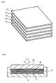
- FIG. 3 is a perspective view illustrating a plurality of square-cut prepregs 17 for configuring the metal backing.
- Reinforcing fiber woven fabric adoptable to the metal backing 14 may be an inorganic fiber woven fabric such as glass fiber woven fabric, and carbon fiber woven fabric; or an organic fiber woven fabric such as aramid resin fiber woven fabric (copolyparaphenylene-3,4'-oxydiphenylene terephthalamide resin fiber woven fabric), each of which is appropriately selectable depending on applications of the multi-layered sliding contact component, proceeded under dry frictional conditions, underwater frictional conditions, boundary frictional conditions and so forth.
- aramid resin fiber woven fabric copolyparaphenylene-3,4'-oxydiphenylene terephthalamide resin fiber woven fabric
- a necessary number of sheets of the prepreg 17 for configuring the metal backing 14, having been square-cut so as to ensure a desired area, are prepared, where the number of sheets is determined so as to obtain a desired final thickness.
- at least one sheet of the prepreg 12 for configuring the sliding contact surface-forming material, having been square-cut similarly to the prepreg 17 for configuring the metal backing 14, is prepared.
- a predetermined number of sheets of prepreg 17 for configuring the metal backing are stacked in a square recess 19 of a die 18 of a heat pressing machine, and the prepregs 12 for configuring the sliding contact surface-forming material are placed thereon.
- the stack is heated to 140 to 160°C in the die 18, and pressed under a load of 4.9 to 7 MPa in the direction of stacking using a ram 20, to thereby obtain a square laminated mold.
- the stacked prepregs 12 for configuring the sliding contact surface-forming material and the prepregs 17 for configuring the metal backing are bonded and fused with each other.
- the thus-obtained laminated mold is machined, to thereby give a flat plate-type multi-layered sliding contact component 13 illustrated in FIG. 5 .
- the flat plate-type multi-layered sliding contact component 13 manufactured as described in the above has the metal backing 14 composed of a stack of inorganic fiber woven fabric or organic fiber woven fabric, and a slipping layer 21 composed of the prepreg 12 for configuring the sliding contact surface-forming material and integrally bonded to one surface of the metal backing 14.
- the slipping layer 21, which is composed of the prepreg 12 for configuring the sliding contact surface-forming material and is integrally bonded on the metal backing 14, is not only excellent in the friction-proof and wear-proof characteristics, but also improved in the load resistance.
- the multi-layered sliding contact component 13 is adoptable to a wide variety of applications proceeded under dry frictional conditions, boundary frictional conditions, and water lubricating conditions.
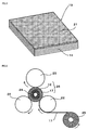
- FIG. 6 and FIG. 7 are drawings illustrating an exemplary method of manufacturing of the circular cylindrical multi-layered sliding contact component, having the sliding contact surface-forming material integrally bonded to the sliding contact surface (inner circumferential surface).
- the circular cylindrical multi-layered sliding contact component may be manufactured by rolled forming using a rolled forming machine.
- a rolled forming machine illustrated in FIG. 6 generally has two heat rollers 22 and one pressure roller 23 respectively located at the apexes of triangle, and a core die 24 located at the center of the triangle, configured to form the circular cylindrical multi-layered sliding contact component while wrapping the prepregs 12 and 17 around the core die 24 and rotating the core die 24 in one direction, under heating and pressurizing by the three rollers 22, 22 and 23.
- rolled forming is conducted so that the prepreg 12 for configuring the sliding contact surface-forming material, slit to a predetermined width, is wrapped at least one turn around the outer circumferential surface of the core die 24 preliminarily heated to 120 to 200°C, the prepreg 17 for configuring the metal backing is fed further on the outer circumferential surface thereof from the feeding roll 25 via the heat rollers 22 heated to 120 to 200°C, and then wound to a desired final thickness (diameter) under a pressure of 2 to 6 MPa with the aid of the pressure roller 23.
- the thus-molded circular cylindrical laminated mold 26 as held around the core die 24, is cured under heating in a heating oven conditioned at an ambient temperature of 120 to 180°C, then cooled, the core die 24 is drawn out, to thereby obtain the circular cylindrical laminated mold 26.
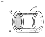
- the thus-manufactured circular cylindrical laminated mold 26 is machined to form a circular cylindrical multi-layered sliding contact component 27 having a desired dimension as illustrated in FIG. 7 .
- the thus-formed circular cylindrical multi-layered sliding contact component 27 has a slipping layer 29 composed of the prepreg 12 for configuring the sliding contact surface-forming material, which is integrally bonded to the inner surface of the circular cylindrical metal backing 28.
- the inner circumferential surface of the slipping layer 29 serves as the sliding contact surface.
- the circular cylindrical multi-layered sliding contact component 27 is excellent in the friction-proof and wear-proof characteristics, improved in the load resistance, causative of an extremely small amount of swelling when used in a moist atmosphere such as in oil or water, and is therefore applicable to a wide variety of applications proceeded under dry frictional conditions, boundary frictional conditions, and water lubricating conditions.
- One each of the single twist yarns were paralleled, and these two single twist yarns were twisted at 275 T/m in the direction (S-direction) opposite to the direction (Z-direction) in which the single twist yarns were spun, to form a ply yarn.
- a flat-woven fabric having a density of 40 picks/inch for the horizontal yarn, and 40 ends/inch for the vertical yarn was produced.
- the flat-woven fabric was used later as a reinforcing base for the sliding contact surface-forming material.
- the content was then added with 64 g of methanol, heated to 85°C under normal pressure, a condensation reaction was allowed to proceed for 4 hours, the content was concentrated, diluted with methanol so as to adjust the resin solid content to 60% by weight, to thereby produce a resol-type phenolic resin (varnish with a solid content of 60% by weight).
- the molar ratio of bisphenol A in the phenolic compound used herein was 100 mol%.
- the obtained resol-type phenolic resin was found to have a number-average molecular weight Mn of 900, and a distribution index Mw/Mn of molecular weight distribution of 5.6.
- a low-molecular-weight PTFE powder (from Kitamura Ltd. KTL-2N (trade name)) was used as PTFE, a predetermined amount of which for each Example was mixed with, and dispersed into the resol-type phenolic resin varnish, to thereby prepare a mixed liquid of the resin varnish and the low-molecular-weight PTFE powder.
- the reinforcing base 2 composed of a flat-woven fabric and preliminarily wound up on the uncoiler 1, was fed with the aid of the feed roller 3 to the container 5 which contains the mixed liquid 4.
- the mixed liquid 4 was coated on the surface of the reinforcing base 2, as the reinforcing base 2 was allowed to pass through the mixed liquid 4 retained in the container 5 with the aid of guide rollers 6 and 7 provided in the container 5.
- the reinforcing base 2 coated with the mixed liquid 4 was fed by thea feed roller 8 to the compression rolls 9 and 10, where the mixed liquid 4 coated on the surface of the reinforcing base 2 was allowed to impregnate deep into voids in the fiber texture by the compression rolls 9 and 10.
- the reinforcing base 2 impregnated with the mixed liquid 4 was then fed to the drying oven 11, where the solvent was vaporized off, and the mixed liquid 4 was allowed to proceed a reaction, to thereby give the prepregs (resin base) 12 for configuring the sliding contact surface-forming material having the compositions listed below:
- the glass fiber flat-woven fabric 15 preliminarily wound up on the uncoiler 1 was fed with the aid of the feed roller 3 to the container 5 which contains the resol-type phenolic resin varnish.
- the resin varnish was coated on the surface of the flat-woven fabric 15, as the flat-woven fabric 15 was allowed to pass through the resol-type phenolic resin varnish 16 retained in the container 5 with the aid of the guide rollers 6 and 7 provided in the container 5.
- the woven fabric 15 coated with the resin varnish was fed by the feed roller 8 to the compression rolls 9 and 10, where the resin varnish was impregnated into the woven fabric 15 by the compression rolls 9 and 10.
- the flat-woven fabric 15 was then fed to the drying oven 11, where the solvent was vaporized off, and the resin varnish was allowed to proceed a reaction, to thereby give the moldable prepregs 17 for configuring the metal backing, having a glass fiber flat-woven fabric content of 40% by weight, and a resol-type phenolic resin content of 60% by weight.
- the prepreg for configuring the metal backing was cut into 31-mm square sheets, and ten sheets were stacked in the square recess 19 of the die 18 of the heat pressing machine illustrated in FIG. 4 .
- each of the prepregs for configuring the sliding contact surface-forming material, obtained in Example 1 to Example 3 was cut into 31-mm square sheets, and three of the sheets were stacked on the prepregs for configuring the metal backing preliminarily stacked in the recess 19 of the die, heated in the die 18 at 160°C for 10 minutes, pressed in the direction of stacking at a pressure of 7 MPa, to thereby obtain a square laminated mold.
- the mold was machined, to thereby give a flat plate-type multi-layered sliding contact component 13 having an edge length of 30 mm and a thickness of 5 mm, composed of the metal backing 14, and the slipping layer 21 composed of the sliding contact surface-forming material integrally bonded to the surface of the metal backing 14.
- One each of the single twist yarns were paralleled, and then twisted (S-twisting) at 295 T/m in the direction (S-direction) opposite to the direction (Z-direction) in which the single twist yarns were spun, to form a ply yarn.
- a flat-woven fabric having a density of 40 picks/inch for the horizontal yarn, and 40 ends/inch for the vertical yarn was produced.
- the flat-woven fabric was used later as a reinforcing base 2 for configuring the sliding contact surface-forming material.
- the content was heated under normal pressure, and allowed to proceed a condensation reaction under a reflux condition at 100°C for 2 hour, and then heated to 80°C under a reduced pressure of 0.015 MPa for dehydration.
- the content was then added with 24 g of methanol, heated to 90°C under normal pressure, a condensation reaction was allowed to proceed for 4 hours, the content was concentrated, diluted with methanol so as to adjust the resin solid content to 60% by weight, to thereby produce a resol-type phenolic resin (varnish with a solid content of 60% by weight).
- the molar ratio of bisphenol A in the phenolic compound used herein was 67.4 mol%.
- the obtained resol-type phenolic resin was found to have a number-average molecular weight Mn of 720, and a distribution index Mw/Mn of molecular weight distribution of 14.3.
- a low-molecular-weight PTFE powder (same as that used in the above-described Examples) was used as PTFE, a predetermined amount of which for each Example was mixed with, and dispersed into the resol-type phenolic resin varnish, to thereby prepare a mixed liquid of the resin varnish and the low-molecular-weight PTFE powder.
- the reinforcing base 2 composed of a flat-woven fabric and preliminarily wound up on the uncoiler 1, was fed with the aid of the feed roller 3 to the container 5 which contains the mixed liquid 4.
- the mixed liquid 4 was coated on the surface of the reinforcing base 2, as the reinforcing base 2 was allowed to pass through the mixed liquid 4 retained in the container 5 with the aid of the guide rollers 6 and 7 provided in the container 5.
- the reinforcing base 2 coated with the mixed liquid 4 was fed by the feed roller 8 to the compression rolls 9 and 10, where the mixed liquid 4 coated on the surface of the reinforcing base 2 was allowed to impregnate deep into voids in the fiber texture by the compression rolls 9 and 10.
- the reinforcing base 2 impregnated with the mixed liquid 4 was then fed to the drying oven 11, where the solvent was vaporized off, and the mixed liquid 4 was allowed to proceed a reaction, to thereby give the prepregs (resin base) for configuring the sliding contact surface-forming material having the compositions listed below:
- the metal backing was manufactured by using the moldable prepreg for configuring the metal backing, having a glass fiber flat-woven fabric content of 40% by weight, and a resol-type phenolic resin content of 60% by weight, which is the same as that used in the above-described Examples.
- the multi-layered sliding contact component having an edge length of 30 mm and a thickness of 5 mm, composed of the metal backing, and the slipping layer composed of the sliding contact surface-forming material integrally bonded to the surface of the metal backing, was manufactured similarly as described in the aforementioned Examples.
- rolled forming was conducted so that the prepreg 12 for configuring the sliding contact surface-forming material, slit into 51-mm wide, same as that described in each of Examples 1 to 3, was wrapped three turns around the outer circumferential surface of the core die 24 having an outer diameter of 60 mm and preliminarily heated to 150°C, the prepreg 17 for configuring the metal backing, same as that described in the aforementioned Examples, was fed further on the outer circumferential surface thereof from the feeding roll 25 via the heat rollers 22 heated to 150°C, and then wound 15 turns under a pressure of 5 MPa with the aid of the pressure roller 23.
- the thus-molded circular cylindrical laminated mold 26 as held around the core die 24, was cured under heating in a heating oven conditioned at an ambient temperature of 150°C, then cooled, the core die 24 was drawn out, to thereby obtain the circular cylindrical laminated mold 26.
- the thus-manufactured circular cylindrical laminated mold 26 was machined to form a circular cylindrical multi-layered sliding contact component 27 having an inner diameter of 60 mm, an outer diameter of 75 mm, and a length of 50 mm, as illustrated in FIG. 7 .
- the circular cylindrical multi-layered sliding contact component 27 of Example 7 was given by using the sliding contact surface-forming material same as that used in Example 1
- the circular cylindrical multi-layered sliding contact component 27 of Example 8 was given by using the sliding contact surface-forming material same as that used in Example 2
- the circular cylindrical multi-layered sliding contact component 27 of Example 9 was given by using the sliding contact surface-forming material same as that used in Example 3.
- rolled forming was conducted so that the prepreg 12 for configuring the sliding contact surface-forming material, slit into 51-mm wide, same as that described in each of Examples 4 to 6, was wrapped three turns around the outer circumferential surface of the core die 24 having an outer diameter of 60 mm and preliminarily heated to 150°C, the prepreg 17 for configuring the metal backing, same as that described in Examples, was fed further on the outer circumferential surface thereof from the feeding roll 25 via the heat rollers 21 heated to 150°C, and then wound 15 turns under a pressure of 5 MPa with the aid of the pressure roller 23.
- the thus-molded circular cylindrical laminated mold 26 as held around the core die 24, was cured under heating in a heating oven conditioned at an ambient temperature of 150°C, then cooled, the core die 24 was drawn out, to thereby obtain the circular cylindrical laminated mold 26.
- the thus-manufactured circular cylindrical laminated mold 26 was machined to form a circular cylindrical multi-layered sliding contact component 27 having an inner diameter of 60 mm, an outer diameter of 75 mm, and a length of 50 mm, as illustrated in FIG. 7 .
- the circular cylindrical multi-layered sliding contact component 27 of Example 10 was given by using the sliding contact surface-forming material same as that used in Example 4, the circular cylindrical multi-layered sliding contact component 27 of Example 11 was given by using the sliding contact surface-forming material same as that used in Example 5, and the circular cylindrical multi-layered sliding contact component 27 of Example 12 was given by using the sliding contact surface-forming material same as that used in Example 4
- the reinforcing fiber woven fabric used herein was a flat-woven fabric which was woven by using a polyester fiber spun yarn of No. 20 cotton count as the warp (vertical yarn) and the weft (horizontal yarn), with a density of 43 ends/inch for the warp, and a density of 42 picks/inch for the weft.
- the prepregs for configuring the sliding contact surface-forming material having the compositions listed below were manufactured:
- the moldable prepreg 16 for configuring the metal backing composed of 40% by weight of glass fiber flat-woven fabric, and 60% by weight of resol-type phenolic resin, same as that described in Example 1 to Example 3, were used as the prepreg for configuring the metal backing.
- the prepreg 17 for configuring the metal backing was cut into 31-mm square sheets, and ten sheets were stacked in the square recess 19 of the die 18 of the heat pressing machine illustrated in FIG. 4 .
- the prepregs 12 for configuring the sliding contact surface-forming material, obtained in Comparative Example 1 was cut into 31-mm square sheets, and three of the sheets were stacked on the prepregs 17 for configuring the metal backing preliminarily stacked in the recess 19 of the die, heated in the die 18 at 160°C for 10 minutes, pressed in the direction of stacking at a pressure of 7 MPa, to thereby obtain a square laminated mold.
- the mold was machined, to thereby give a multi-layered sliding contact component 13 having an edge length of 30 mm and a thickness of 5 mm, composed of the metal backing 14, and the slipping layer 21 composed of the sliding contact surface-forming material integrally bonded to the surface of the metal backing 14.
- rolled forming was conducted so that the prepreg 12 for configuring the sliding contact surface-forming material, slit into 51-mm wide, same as that described in each of Comparative Examples 1 to 3, was wrapped three turns around the outer circumferential surface of the core die 24 having an outer diameter of 60 mm and preliminarily heated to 150°C, the prepreg 16 for configuring the metal backing, same as that described in Examples 1 to 3, was fed further on the outer circumferential surface thereof from the feeding roll 25 via the heat rollers 22 heated to 150°C, and then wound 15 turns under a pressure of 5 MPa with the aid of the pressure roller 23.
- the thus-molded circular cylindrical laminated mold 26 as held around the core die 24, was cured under heating in a heating oven conditioned at an ambient temperature of 150°C, then cooled, the core die 24 was drawn out, to thereby obtain the circular cylindrical laminated mold 26.
- the thus-manufactured circular cylindrical laminated mold 26 was machined to form a circular cylindrical multi-layered sliding contact component 27 having an inner diameter of 60 mm, an outer diameter of 75 mm, and a length of 50 mm, as illustrated in FIG. 7 .
- the circular cylindrical multi-layered sliding contact component 27 of Comparative Example 4 was given by using the sliding contact surface-forming material same as that used in Comparative Example 1
- the circular cylindrical multi-layered sliding contact component 27 of Comparative Example 5 was given by using the sliding contact surface-forming material same as that used in Comparative Example 2
- the circular cylindrical multi-layered sliding contact component 27 of Comparative Example 6 was given by using the sliding contact surface-forming material same as that used in Comparative Example 3.
- the friction coefficient and amount of wear were measured according to the test conditions listed in Table 1.
- the amount of wear was represented by the amount of dimensional change observed after the 30-hour testing.
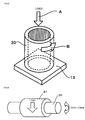
- a flat plate-type bearing test piece (multi-layered sliding contact component) 13 was fixed, an opposing circular cylinder 30 was allowed to rotate in the direction of arrow B, on the flat plate-type bearing test piece 13 (from the direction of arrow "A") while applying a predetermined load to the surface thereof, and the friction coefficient between the flat plate-type bearing test piece 13 and the circular cylinder 30, and the amount the wear (mm) of the flat plate-type bearing test piece 13 after the elapse of 30 hours were measured.
- the friction coefficient and amount of wear were measured according to the test conditions listed in Tables 2 and 3.
- the amount of wear was represented by the amount of dimensional change observed after the 100-hour testing.
- a circular cylindrical bearing test piece (circular cylindrical multi-layered sliding contact component) 27 was fixed under load, an opposing rotating shaft 31 was allowed to rotate under oscillation at a constant sliding velocity, then the friction coefficient between the circular cylindrical bearing test piece 27 and the rotating shaft 31, and the amount of wear (mm) on the inner circumferential surface (sliding contact surface) of the circular cylindrical bearing test piece 27 after the elapse of 100 hours were measured.
- test pieces were immersed in water at 20°C for 120 days, and then taken out for measurement of rate of dimensional change.
- Results of test on the friction and wear, and on the amount of swelling are shown in Table 4 to Table 6.
- the number-average molecular weight Mn and distribution index Mw/Mn of the resol-type phenolic resin were measured by GPC, and the values were estimated based on a standard curve prepared by using polystyrene as a standard substance.
- GPC analyzer HLC-8120 from Tosoh Corporation; Column: TSK gel G3000HXL [exclusion limit molecular weight (polystyrene-based) 1 ⁇ 10 3 ] ⁇ 1, followed by TSK gel G2000HXL [exclusion limit molecular weight (polystyrene-based) 1 ⁇ 10 4 ] ⁇ 2, from Tosoh Corporation; and Detector: UV-8020 from Tosoh Corporation
- the reinforcing base which configures the sliding contact surface-forming material of the present invention, and is composed of a woven fabric formed by using, respectively as the warp and the weft, a ply yarn formed by paralleling at least two strands of a single twist yarn spun from fluorine-containing resin fiber and a single twist yarn spun from polyester fiber, and by twisting them in the direction opposite to the direction in which the single twist yarns were spun, allows the fluorine-containing resin fiber and the polyester fiber to expose on at least one surface thereof which serves as the sliding contact surface, while keeping almost equal areas of exposure.
- the present invention therefore successfully provides a sliding contact surface-forming material, improved in the friction-proof and wear-proof characteristics contributed by low friction properties of the PTFE powder impregnated into the woven fabric.
- the multi-layered sliding contact component which has such sliding contact surface-forming material so as to configure the sliding contact surface, has excellent friction-proof and wear-proof characteristics, high rigidity, and excellent mechanical strength.
- the multi-layered sliding contact component shows an extremely small amount of swelling in moist atmosphere such as underwater, so that dimensional changes ascribable the swelling will be extremely small, and this makes the component adoptable to a wide variety of applications proceeded under dry frictional conditions, grease lubricating conditions, and water lubricating conditions.
Landscapes
- Engineering & Computer Science (AREA)
- General Engineering & Computer Science (AREA)
- Mechanical Engineering (AREA)
- Manufacturing & Machinery (AREA)
- Sliding-Contact Bearings (AREA)
- Reinforced Plastic Materials (AREA)
Applications Claiming Priority (2)
| Application Number | Priority Date | Filing Date | Title |
|---|---|---|---|
| JP2009228146A JP5595705B2 (ja) | 2009-09-30 | 2009-09-30 | 摺動面材及び該摺動面材を備えた複層摺動部材 |
| PCT/JP2010/004562 WO2011039916A1 (fr) | 2009-09-30 | 2010-07-14 | Matériau pour surface de glissement et élément de glissement multicouche en comportant |
Publications (3)
| Publication Number | Publication Date |
|---|---|
| EP2484712A1 true EP2484712A1 (fr) | 2012-08-08 |
| EP2484712A4 EP2484712A4 (fr) | 2013-03-13 |
| EP2484712B1 EP2484712B1 (fr) | 2016-09-28 |
Family
ID=43825770
Family Applications (1)
| Application Number | Title | Priority Date | Filing Date |
|---|---|---|---|
| EP10820042.9A Not-in-force EP2484712B1 (fr) | 2009-09-30 | 2010-07-14 | Matériau pour surface de glissement et élément de glissement multicouche en comportant |
Country Status (5)
| Country | Link |
|---|---|
| US (2) | US10267362B2 (fr) |
| EP (1) | EP2484712B1 (fr) |
| JP (1) | JP5595705B2 (fr) |
| CN (1) | CN102597073B (fr) |
| WO (1) | WO2011039916A1 (fr) |
Cited By (1)
| Publication number | Priority date | Publication date | Assignee | Title |
|---|---|---|---|---|
| EP3333289A4 (fr) * | 2015-08-05 | 2019-08-21 | Toray Industries, Inc. | Tissu autolubrifiant, procédé de production et utilisation de ce dernier |
Families Citing this family (12)
| Publication number | Priority date | Publication date | Assignee | Title |
|---|---|---|---|---|
| JP5859183B2 (ja) * | 2009-09-30 | 2016-02-10 | オイレス工業株式会社 | 摺動面材及び該摺動面材を備えた複層摺動部材 |
| FR2961740B1 (fr) * | 2010-06-25 | 2014-03-07 | Snecma | Procede de fabrication d'un article en materiau composite |
| JP6067307B2 (ja) * | 2012-10-01 | 2017-01-25 | オイレス工業株式会社 | 複層摺動部材の製造方法 |
| WO2015111574A1 (fr) * | 2014-01-22 | 2015-07-30 | オイレス工業株式会社 | Élément glissant |
| CN105013250B (zh) * | 2015-07-02 | 2017-08-01 | 辽宁鸿盛环境技术集团股份有限公司 | 一种具有脱硫功效的过滤材料及其制备方法 |
| JP6604208B2 (ja) * | 2016-01-08 | 2019-11-13 | 住友ゴム工業株式会社 | ビードクランプリング |
| CN106523514A (zh) * | 2016-11-10 | 2017-03-22 | 长春安旨科技有限公司 | 耐高温高分子自润滑轴承及其制备方法 |
| CN109624168A (zh) * | 2018-10-31 | 2019-04-16 | 广东出入境检验检疫局检验检疫技术中心 | 一种自润滑凹槽型摩擦装置及其制备方法 |
| EP4079470B1 (fr) * | 2019-12-20 | 2025-03-05 | Toray Industries, Inc. | Tissu et revêtement de câble pour bras de robot |
| FR3120563B1 (fr) * | 2021-03-11 | 2023-03-17 | Hexcel Reinforcements | Nouveaux matériaux de renfort à base de fils torsadés S et Z, adaptés à la constitution de pièces composites, procédés et utilisation |
| US12297864B2 (en) * | 2021-08-12 | 2025-05-13 | Roller Bearing Company Of America, Inc. | Self lubricating linear guide bushings for reciprocating canning and bottling machinery |
| CN115058895B (zh) * | 2022-06-06 | 2023-07-04 | 清华大学 | 纤维复合材料及其制备方法和应用 |
Family Cites Families (9)
| Publication number | Priority date | Publication date | Assignee | Title |
|---|---|---|---|---|
| DE4010694A1 (de) * | 1990-04-03 | 1991-10-10 | Hoechst Ag | Faserverstaerkter werkstoff, verfahren zu seiner herstellung und seine verwendung |
| US5880043A (en) * | 1991-04-03 | 1999-03-09 | Hoechst Aktiengesellschaft | Fiber-reinforced material and production and use thereof |
| EP0585874B1 (fr) | 1992-09-04 | 1997-03-12 | Hoechst Aktiengesellschaft | Fil mélangé pour la fabrication de la couche de glissement de paliers à contact lisse en matières thermoplastiques renforcées par des fibres |
| DE10159502C2 (de) * | 2001-12-04 | 2003-12-04 | Federal Mogul Deva Gmbh | Verbundgleitlager |
| JP2005105469A (ja) * | 2003-09-30 | 2005-04-21 | Nisshinbo Ind Inc | 複合糸と織編物 |
| JP5026215B2 (ja) | 2007-10-09 | 2012-09-12 | オイレス工業株式会社 | 摺動部材用繊維強化樹脂組成物及び積層摺動部材 |
| JP5215630B2 (ja) * | 2007-10-23 | 2013-06-19 | オイレス工業株式会社 | 摺動部材 |
| JP5249726B2 (ja) * | 2008-11-17 | 2013-07-31 | オイレス工業株式会社 | 摺動部材用繊維強化樹脂組成物及び積層摺動部材 |
| JP5859183B2 (ja) * | 2009-09-30 | 2016-02-10 | オイレス工業株式会社 | 摺動面材及び該摺動面材を備えた複層摺動部材 |
-
2009
- 2009-09-30 JP JP2009228146A patent/JP5595705B2/ja active Active
-
2010
- 2010-07-14 CN CN201080043181.6A patent/CN102597073B/zh active Active
- 2010-07-14 WO PCT/JP2010/004562 patent/WO2011039916A1/fr not_active Ceased
- 2010-07-14 EP EP10820042.9A patent/EP2484712B1/fr not_active Not-in-force
- 2010-07-14 US US13/496,915 patent/US10267362B2/en active Active
-
2018
- 2018-07-31 US US16/050,296 patent/US10767697B2/en active Active
Cited By (1)
| Publication number | Priority date | Publication date | Assignee | Title |
|---|---|---|---|---|
| EP3333289A4 (fr) * | 2015-08-05 | 2019-08-21 | Toray Industries, Inc. | Tissu autolubrifiant, procédé de production et utilisation de ce dernier |
Also Published As
| Publication number | Publication date |
|---|---|
| CN102597073A (zh) | 2012-07-18 |
| JP5595705B2 (ja) | 2014-09-24 |
| WO2011039916A1 (fr) | 2011-04-07 |
| US20120178327A1 (en) | 2012-07-12 |
| CN102597073B (zh) | 2015-11-25 |
| JP2011074259A (ja) | 2011-04-14 |
| EP2484712A4 (fr) | 2013-03-13 |
| US10767697B2 (en) | 2020-09-08 |
| US10267362B2 (en) | 2019-04-23 |
| US20180335083A1 (en) | 2018-11-22 |
| EP2484712B1 (fr) | 2016-09-28 |
Similar Documents
| Publication | Publication Date | Title |
|---|---|---|
| US10767697B2 (en) | Sliding contact surface-forming material, slide bearing containing same, and method of using same in a moist environment | |
| US10767695B2 (en) | Sliding contact surface-forming material, slide bearing containing same, and method of using same in a moist environment | |
| JP5026216B2 (ja) | 摺動部材用繊維強化樹脂組成物及び積層摺動部材 | |
| JP5249726B2 (ja) | 摺動部材用繊維強化樹脂組成物及び積層摺動部材 | |
| EP2623802A1 (fr) | Cage pour roulement et roulement | |
| JP6143588B2 (ja) | 積層すべり部材及びこの積層すべり部材を使用したすべり支承 | |
| CN104471270B (zh) | 偏航控制用制动块及制动构件 | |
| JP2002323038A (ja) | 水中用摺動部材ならびにその製造方法 | |
| JP5026215B2 (ja) | 摺動部材用繊維強化樹脂組成物及び積層摺動部材 | |
| JP5691553B2 (ja) | 耐圧摺動部材及びブレーキパッド | |
| EP3189124B1 (fr) | Palier composite présentant une usure et une usinabilité améliorées | |
| JP5216170B2 (ja) | 摺動部材 | |
| RU2313010C1 (ru) | Связующее для получения антифрикционных изделий, препрег и изделие, выполненное из него | |
| JP2010196894A (ja) | 水中用摺動部材ならびにその製造方法 | |
| CN121183563A (zh) | 一种耐高温高强度低磨损自润滑织物衬垫复合材料及其制备方法和摩擦副 | |
| JP2017019886A (ja) | 摺動部材及び風車のヨー制御用ブレーキ部材 |
Legal Events
| Date | Code | Title | Description |
|---|---|---|---|
| PUAI | Public reference made under article 153(3) epc to a published international application that has entered the european phase |
Free format text: ORIGINAL CODE: 0009012 |
|
| 17P | Request for examination filed |
Effective date: 20120320 |
|
| AK | Designated contracting states |
Kind code of ref document: A1 Designated state(s): AL AT BE BG CH CY CZ DE DK EE ES FI FR GB GR HR HU IE IS IT LI LT LU LV MC MK MT NL NO PL PT RO SE SI SK SM TR |
|
| DAX | Request for extension of the european patent (deleted) | ||
| A4 | Supplementary search report drawn up and despatched |
Effective date: 20130213 |
|
| RIC1 | Information provided on ipc code assigned before grant |
Ipc: F16C 33/20 20060101ALI20130207BHEP Ipc: F16C 17/02 20060101ALI20130207BHEP Ipc: C08J 5/16 20060101AFI20130207BHEP |
|
| GRAP | Despatch of communication of intention to grant a patent |
Free format text: ORIGINAL CODE: EPIDOSNIGR1 |
|
| INTG | Intention to grant announced |
Effective date: 20160419 |
|
| GRAS | Grant fee paid |
Free format text: ORIGINAL CODE: EPIDOSNIGR3 |
|
| GRAA | (expected) grant |
Free format text: ORIGINAL CODE: 0009210 |
|
| AK | Designated contracting states |
Kind code of ref document: B1 Designated state(s): AL AT BE BG CH CY CZ DE DK EE ES FI FR GB GR HR HU IE IS IT LI LT LU LV MC MK MT NL NO PL PT RO SE SI SK SM TR |
|
| REG | Reference to a national code |
Ref country code: GB Ref legal event code: FG4D |
|
| REG | Reference to a national code |
Ref country code: CH Ref legal event code: EP |
|
| REG | Reference to a national code |
Ref country code: AT Ref legal event code: REF Ref document number: 832700 Country of ref document: AT Kind code of ref document: T Effective date: 20161015 |
|
| REG | Reference to a national code |
Ref country code: IE Ref legal event code: FG4D |
|
| REG | Reference to a national code |
Ref country code: DE Ref legal event code: R096 Ref document number: 602010036834 Country of ref document: DE |
|
| REG | Reference to a national code |
Ref country code: LT Ref legal event code: MG4D |
|
| PG25 | Lapsed in a contracting state [announced via postgrant information from national office to epo] |
Ref country code: HR Free format text: LAPSE BECAUSE OF FAILURE TO SUBMIT A TRANSLATION OF THE DESCRIPTION OR TO PAY THE FEE WITHIN THE PRESCRIBED TIME-LIMIT Effective date: 20160928 Ref country code: LT Free format text: LAPSE BECAUSE OF FAILURE TO SUBMIT A TRANSLATION OF THE DESCRIPTION OR TO PAY THE FEE WITHIN THE PRESCRIBED TIME-LIMIT Effective date: 20160928 Ref country code: NO Free format text: LAPSE BECAUSE OF FAILURE TO SUBMIT A TRANSLATION OF THE DESCRIPTION OR TO PAY THE FEE WITHIN THE PRESCRIBED TIME-LIMIT Effective date: 20161228 Ref country code: FI Free format text: LAPSE BECAUSE OF FAILURE TO SUBMIT A TRANSLATION OF THE DESCRIPTION OR TO PAY THE FEE WITHIN THE PRESCRIBED TIME-LIMIT Effective date: 20160928 |
|
| REG | Reference to a national code |
Ref country code: NL Ref legal event code: MP Effective date: 20160928 |
|
| PG25 | Lapsed in a contracting state [announced via postgrant information from national office to epo] |
Ref country code: NL Free format text: LAPSE BECAUSE OF FAILURE TO SUBMIT A TRANSLATION OF THE DESCRIPTION OR TO PAY THE FEE WITHIN THE PRESCRIBED TIME-LIMIT Effective date: 20160928 Ref country code: GR Free format text: LAPSE BECAUSE OF FAILURE TO SUBMIT A TRANSLATION OF THE DESCRIPTION OR TO PAY THE FEE WITHIN THE PRESCRIBED TIME-LIMIT Effective date: 20161229 Ref country code: SE Free format text: LAPSE BECAUSE OF FAILURE TO SUBMIT A TRANSLATION OF THE DESCRIPTION OR TO PAY THE FEE WITHIN THE PRESCRIBED TIME-LIMIT Effective date: 20160928 Ref country code: LV Free format text: LAPSE BECAUSE OF FAILURE TO SUBMIT A TRANSLATION OF THE DESCRIPTION OR TO PAY THE FEE WITHIN THE PRESCRIBED TIME-LIMIT Effective date: 20160928 |
|
| PG25 | Lapsed in a contracting state [announced via postgrant information from national office to epo] |
Ref country code: EE Free format text: LAPSE BECAUSE OF FAILURE TO SUBMIT A TRANSLATION OF THE DESCRIPTION OR TO PAY THE FEE WITHIN THE PRESCRIBED TIME-LIMIT Effective date: 20160928 Ref country code: RO Free format text: LAPSE BECAUSE OF FAILURE TO SUBMIT A TRANSLATION OF THE DESCRIPTION OR TO PAY THE FEE WITHIN THE PRESCRIBED TIME-LIMIT Effective date: 20160928 |
|
| PG25 | Lapsed in a contracting state [announced via postgrant information from national office to epo] |
Ref country code: IS Free format text: LAPSE BECAUSE OF FAILURE TO SUBMIT A TRANSLATION OF THE DESCRIPTION OR TO PAY THE FEE WITHIN THE PRESCRIBED TIME-LIMIT Effective date: 20170128 Ref country code: PT Free format text: LAPSE BECAUSE OF FAILURE TO SUBMIT A TRANSLATION OF THE DESCRIPTION OR TO PAY THE FEE WITHIN THE PRESCRIBED TIME-LIMIT Effective date: 20170130 Ref country code: PL Free format text: LAPSE BECAUSE OF FAILURE TO SUBMIT A TRANSLATION OF THE DESCRIPTION OR TO PAY THE FEE WITHIN THE PRESCRIBED TIME-LIMIT Effective date: 20160928 Ref country code: ES Free format text: LAPSE BECAUSE OF FAILURE TO SUBMIT A TRANSLATION OF THE DESCRIPTION OR TO PAY THE FEE WITHIN THE PRESCRIBED TIME-LIMIT Effective date: 20160928 Ref country code: BG Free format text: LAPSE BECAUSE OF FAILURE TO SUBMIT A TRANSLATION OF THE DESCRIPTION OR TO PAY THE FEE WITHIN THE PRESCRIBED TIME-LIMIT Effective date: 20161228 Ref country code: SM Free format text: LAPSE BECAUSE OF FAILURE TO SUBMIT A TRANSLATION OF THE DESCRIPTION OR TO PAY THE FEE WITHIN THE PRESCRIBED TIME-LIMIT Effective date: 20160928 Ref country code: CZ Free format text: LAPSE BECAUSE OF FAILURE TO SUBMIT A TRANSLATION OF THE DESCRIPTION OR TO PAY THE FEE WITHIN THE PRESCRIBED TIME-LIMIT Effective date: 20160928 Ref country code: BE Free format text: LAPSE BECAUSE OF FAILURE TO SUBMIT A TRANSLATION OF THE DESCRIPTION OR TO PAY THE FEE WITHIN THE PRESCRIBED TIME-LIMIT Effective date: 20160928 Ref country code: SK Free format text: LAPSE BECAUSE OF FAILURE TO SUBMIT A TRANSLATION OF THE DESCRIPTION OR TO PAY THE FEE WITHIN THE PRESCRIBED TIME-LIMIT Effective date: 20160928 |
|
| REG | Reference to a national code |
Ref country code: FR Ref legal event code: PLFP Year of fee payment: 8 |
|
| REG | Reference to a national code |
Ref country code: DE Ref legal event code: R097 Ref document number: 602010036834 Country of ref document: DE |
|
| PG25 | Lapsed in a contracting state [announced via postgrant information from national office to epo] |
Ref country code: IT Free format text: LAPSE BECAUSE OF FAILURE TO SUBMIT A TRANSLATION OF THE DESCRIPTION OR TO PAY THE FEE WITHIN THE PRESCRIBED TIME-LIMIT Effective date: 20160928 |
|
| PG25 | Lapsed in a contracting state [announced via postgrant information from national office to epo] |
Ref country code: DK Free format text: LAPSE BECAUSE OF FAILURE TO SUBMIT A TRANSLATION OF THE DESCRIPTION OR TO PAY THE FEE WITHIN THE PRESCRIBED TIME-LIMIT Effective date: 20160928 |
|
| PLBE | No opposition filed within time limit |
Free format text: ORIGINAL CODE: 0009261 |
|
| STAA | Information on the status of an ep patent application or granted ep patent |
Free format text: STATUS: NO OPPOSITION FILED WITHIN TIME LIMIT |
|
| 26N | No opposition filed |
Effective date: 20170629 |
|
| PG25 | Lapsed in a contracting state [announced via postgrant information from national office to epo] |
Ref country code: SI Free format text: LAPSE BECAUSE OF FAILURE TO SUBMIT A TRANSLATION OF THE DESCRIPTION OR TO PAY THE FEE WITHIN THE PRESCRIBED TIME-LIMIT Effective date: 20160928 |
|
| REG | Reference to a national code |
Ref country code: CH Ref legal event code: PL |
|
| GBPC | Gb: european patent ceased through non-payment of renewal fee |
Effective date: 20170714 |
|
| REG | Reference to a national code |
Ref country code: IE Ref legal event code: MM4A |
|
| PG25 | Lapsed in a contracting state [announced via postgrant information from national office to epo] |
Ref country code: GB Free format text: LAPSE BECAUSE OF NON-PAYMENT OF DUE FEES Effective date: 20170714 Ref country code: LI Free format text: LAPSE BECAUSE OF NON-PAYMENT OF DUE FEES Effective date: 20170731 Ref country code: CH Free format text: LAPSE BECAUSE OF NON-PAYMENT OF DUE FEES Effective date: 20170731 Ref country code: IE Free format text: LAPSE BECAUSE OF NON-PAYMENT OF DUE FEES Effective date: 20170714 |
|
| REG | Reference to a national code |
Ref country code: FR Ref legal event code: PLFP Year of fee payment: 9 |
|
| PG25 | Lapsed in a contracting state [announced via postgrant information from national office to epo] |
Ref country code: LU Free format text: LAPSE BECAUSE OF NON-PAYMENT OF DUE FEES Effective date: 20170714 |
|
| REG | Reference to a national code |
Ref country code: AT Ref legal event code: UEP Ref document number: 832700 Country of ref document: AT Kind code of ref document: T Effective date: 20160928 |
|
| PG25 | Lapsed in a contracting state [announced via postgrant information from national office to epo] |
Ref country code: MT Free format text: LAPSE BECAUSE OF NON-PAYMENT OF DUE FEES Effective date: 20170714 |
|
| PG25 | Lapsed in a contracting state [announced via postgrant information from national office to epo] |
Ref country code: AL Free format text: LAPSE BECAUSE OF FAILURE TO SUBMIT A TRANSLATION OF THE DESCRIPTION OR TO PAY THE FEE WITHIN THE PRESCRIBED TIME-LIMIT Effective date: 20160928 |
|
| PG25 | Lapsed in a contracting state [announced via postgrant information from national office to epo] |
Ref country code: HU Free format text: LAPSE BECAUSE OF FAILURE TO SUBMIT A TRANSLATION OF THE DESCRIPTION OR TO PAY THE FEE WITHIN THE PRESCRIBED TIME-LIMIT; INVALID AB INITIO Effective date: 20100714 Ref country code: MC Free format text: LAPSE BECAUSE OF FAILURE TO SUBMIT A TRANSLATION OF THE DESCRIPTION OR TO PAY THE FEE WITHIN THE PRESCRIBED TIME-LIMIT Effective date: 20160928 |
|
| PG25 | Lapsed in a contracting state [announced via postgrant information from national office to epo] |
Ref country code: CY Free format text: LAPSE BECAUSE OF NON-PAYMENT OF DUE FEES Effective date: 20160928 |
|
| PG25 | Lapsed in a contracting state [announced via postgrant information from national office to epo] |
Ref country code: MK Free format text: LAPSE BECAUSE OF FAILURE TO SUBMIT A TRANSLATION OF THE DESCRIPTION OR TO PAY THE FEE WITHIN THE PRESCRIBED TIME-LIMIT Effective date: 20160928 |
|
| PG25 | Lapsed in a contracting state [announced via postgrant information from national office to epo] |
Ref country code: TR Free format text: LAPSE BECAUSE OF FAILURE TO SUBMIT A TRANSLATION OF THE DESCRIPTION OR TO PAY THE FEE WITHIN THE PRESCRIBED TIME-LIMIT Effective date: 20160928 |
|
| PGFP | Annual fee paid to national office [announced via postgrant information from national office to epo] |
Ref country code: FR Payment date: 20220609 Year of fee payment: 13 |
|
| PGFP | Annual fee paid to national office [announced via postgrant information from national office to epo] |
Ref country code: DE Payment date: 20220531 Year of fee payment: 13 Ref country code: AT Payment date: 20220627 Year of fee payment: 13 |
|
| REG | Reference to a national code |
Ref country code: DE Ref legal event code: R119 Ref document number: 602010036834 Country of ref document: DE |
|
| REG | Reference to a national code |
Ref country code: AT Ref legal event code: MM01 Ref document number: 832700 Country of ref document: AT Kind code of ref document: T Effective date: 20230714 |
|
| PG25 | Lapsed in a contracting state [announced via postgrant information from national office to epo] |
Ref country code: AT Free format text: LAPSE BECAUSE OF NON-PAYMENT OF DUE FEES Effective date: 20230714 |
|
| PG25 | Lapsed in a contracting state [announced via postgrant information from national office to epo] |
Ref country code: DE Free format text: LAPSE BECAUSE OF NON-PAYMENT OF DUE FEES Effective date: 20240201 Ref country code: AT Free format text: LAPSE BECAUSE OF NON-PAYMENT OF DUE FEES Effective date: 20230714 |
|
| PG25 | Lapsed in a contracting state [announced via postgrant information from national office to epo] |
Ref country code: FR Free format text: LAPSE BECAUSE OF NON-PAYMENT OF DUE FEES Effective date: 20230731 |