EP2485221A1 - Druckfeste dielektrische Struktur - Google Patents
Druckfeste dielektrische Struktur Download PDFInfo
- Publication number
- EP2485221A1 EP2485221A1 EP12151756A EP12151756A EP2485221A1 EP 2485221 A1 EP2485221 A1 EP 2485221A1 EP 12151756 A EP12151756 A EP 12151756A EP 12151756 A EP12151756 A EP 12151756A EP 2485221 A1 EP2485221 A1 EP 2485221A1
- Authority
- EP
- European Patent Office
- Prior art keywords
- spacer
- structure according
- spacers
- walls
- wall
- Prior art date
- Legal status (The legal status is an assumption and is not a legal conclusion. Google has not performed a legal analysis and makes no representation as to the accuracy of the status listed.)
- Withdrawn
Links
- 230000006835 compression Effects 0.000 title description 15
- 238000007906 compression Methods 0.000 title description 15
- 125000006850 spacer group Chemical group 0.000 claims abstract description 50
- 238000001125 extrusion Methods 0.000 claims abstract description 6
- 238000000034 method Methods 0.000 description 7
- 238000004519 manufacturing process Methods 0.000 description 5
- 241000723353 Chrysanthemum Species 0.000 description 4
- 235000005633 Chrysanthemum balsamita Nutrition 0.000 description 4
- 229910003460 diamond Inorganic materials 0.000 description 4
- 239000010432 diamond Substances 0.000 description 4
- 230000035939 shock Effects 0.000 description 3
- 230000007547 defect Effects 0.000 description 2
- 238000010586 diagram Methods 0.000 description 2
- 230000006355 external stress Effects 0.000 description 2
- 238000005187 foaming Methods 0.000 description 2
- 230000004048 modification Effects 0.000 description 2
- 238000012986 modification Methods 0.000 description 2
- 230000035882 stress Effects 0.000 description 2
- 230000001154 acute effect Effects 0.000 description 1
- 230000000052 comparative effect Effects 0.000 description 1
- 230000000694 effects Effects 0.000 description 1
- 239000006260 foam Substances 0.000 description 1
- 239000000463 material Substances 0.000 description 1
- 230000002250 progressing effect Effects 0.000 description 1
- 230000000135 prohibitive effect Effects 0.000 description 1
- 230000002787 reinforcement Effects 0.000 description 1
Images


Classifications
-
- H—ELECTRICITY
- H01—ELECTRIC ELEMENTS
- H01B—CABLES; CONDUCTORS; INSULATORS; SELECTION OF MATERIALS FOR THEIR CONDUCTIVE, INSULATING OR DIELECTRIC PROPERTIES
- H01B7/00—Insulated conductors or cables characterised by their form
- H01B7/17—Protection against damage caused by external factors, e.g. sheaths or armouring
- H01B7/18—Protection against damage caused by wear, mechanical force or pressure; Sheaths; Armouring
- H01B7/185—Sheaths comprising internal cavities or channels
-
- H—ELECTRICITY
- H01—ELECTRIC ELEMENTS
- H01B—CABLES; CONDUCTORS; INSULATORS; SELECTION OF MATERIALS FOR THEIR CONDUCTIVE, INSULATING OR DIELECTRIC PROPERTIES
- H01B11/00—Communication cables or conductors
- H01B11/02—Cables with twisted pairs or quads
-
- H—ELECTRICITY
- H01—ELECTRIC ELEMENTS
- H01B—CABLES; CONDUCTORS; INSULATORS; SELECTION OF MATERIALS FOR THEIR CONDUCTIVE, INSULATING OR DIELECTRIC PROPERTIES
- H01B7/00—Insulated conductors or cables characterised by their form
- H01B7/02—Disposition of insulation
- H01B7/0233—Cables with a predominant gas dielectric
Definitions
- the invention relates to a dielectric structure for an electric wire or cable.
- electrical cables or wires are surrounded by a dielectric structure to electrically isolate them from all external elements.
- these dielectric structures are dimensioned so as to have good mechanical strength.
- these dielectric structures absorb, partially or totally, the forces caused during these unwanted solicitations, by deforming more or less.
- dielectric structures having an acceptable compressibility are constituted by "daisy” type structures.
- these structures 1 have an inner hollow cylindrical body 2, and an outer hollow cylindrical body 3, said bodies 2, 3 being concentric and being interconnected by radial walls 4a, regularly spaced apart in the annular space separating said hollow bodies 2 3. These walls are flat and delimit a plurality of compartments 5.
- these structures tend to deform strongly, beyond a threshold external stress, compression type, just preserving the integrity of the inner body 2, and therefore that of the wire or electrical cable housed inside said body 2.
- these "daisy” structures have the additional disadvantage of repeatedly presenting manufacturing defects inherent in the extrusion process which implements them. Indeed, as shown by Figures 1b and 1c , the walls 4c may not be perfectly radial, or said walls 4b may have material concentration gradients, these two manufacturing approximations may be prohibitive vis-à-vis the good mechanical strength sought, by accelerating the process of appearance of significant deformation.
- Other dielectric structures can exhibit interesting mechanical strength properties compared to a compression type stress. These are dielectric foam structures. However, the use of freon as a foaming gas is no longer allowed today, and these foaming structures can no longer be satisfactory solutions to the problem.
- the dielectric structures according to the invention have a particular geometry giving them an excellent aptitude for mechanical resistance, in particular with respect to a crushing, which could, for example, be due to an external stress of the compression type.
- these structures can be manufactured easily and quickly, and the few defects that may occur during their manufacture, would not be likely to question the mechanical strength of said structures, because of their particular geometry that can tolerate some manufacturing approximations .
- the invention relates to a dielectric structure of wire or electric cable, having a hollow inner cylindrical body and a hollow outer cylindrical body, said bodies being concentric and being connected to one another by a plurality of spacers.
- the main characteristic of a structure according to the invention is that each spacer consists of a first curved wall and a second wall curved in the other direction, with respect to a radial plane connecting the two bodies, said walls having at least one intersection zone, and two successive spacers being in contact with each other.
- the objective of this specific geometry of the spacers occupying the interspace between the two hollow bodies is to be able to cancel the effect of the forces transmitted in the structure during external compression, so as to cause only one minimal deformation of said structure, or even to preserve its initial shape.
- each spacer associated with their arrangement relative to each other, allows to highlight a continuous series of walls positioned in geometric opposition two by two, thus canceling the forces transmitted in the structure when a compression.
- the shock which initially has a radial component, is transmitted along the walls of each spacer in a substantially radial direction, until reaching the zone intersection of the walls of each spacer. At each of these intersection zones, the shock then has two tangential and opposite components, which cancel each other out, preventing the shock from progressing towards the hollow inner body.
- said structure comprises twenty-one identical spacers.
- each spacer is composed of two curved walls, the section of said spacer having a shape substantially X.
- the fact that the zone of intersection of the two walls, corresponds to a contact with their central part, does not does not mean that this contact takes place precisely and precisely at the level of their geometric center.
- the central portion of each wall is considered extended in a radial direction of the structure, and the intersection zone can be made at an eccentric subpart of this central portion, along a radial axis. In this way, according to the configurations encountered, this intersection zone can be found, either closer to the inner body, or closer to the outer body, or equidistant from said bodies.
- two successive spacers are in contact with each other, the first spacer having a wall which is in contact with a wall of the second spacer, said contact being made at both ends of each wall.
- This configuration can be summed up to a contacting of two objects each having an identical X-shaped section, this contacting reverberating continuously around the interspace separating the two hollow bodies.
- each spacer has an X-shaped section, and the contacting of two spacers located at the same height, allows to highlight a interstice "inter spacers" shaped diamond.
- the two rounded corners come from the curved form of the walls of the spacers. The fact of removing two angular peaks of the diamond, makes it possible to remove two rupture zones, likely to promote the crushing of the structure in the case of compression.
- each rhombus is elongate in a radial direction of the structure.
- the ratio of the width of the diamond over its length is between 0.3 and 0.7.
- the length of the diamond is its dimension taken along a radial axis of the structure, and its width is its dimension taken along a tangential axis of said structure.
- the two walls of the same spacer have two intersection zones, to secure their ends.
- each spacer reveals a central recess, having the shape of a rhombus.
- the two vertices of the rhombus connected by an axis tangential to the structure are rounded.
- the central recess has substantially an oblong shape, widened at its central portion. The fact that vertices are rounded means that vertices are not angular, and therefore do not have an edge likely to constitute a breaking line during compression.
- the dielectric structure is made in one piece, by extrusion.
- the dielectric structures for cables or electrical wires according to the invention have the advantage of having substantially greater compressive strength properties compared to existing structures, by a simple geometric modification, requiring no complex manufacturing technique, nor adding reinforcement pieces.
- this modification preserves the general outline of the structure, allowing it to replace the existing structures, without making any fitting or readjustment of assembly.
- a dielectric structure has an inner hollow cylindrical body 2 and an outer hollow cylindrical body 3, interconnected by a plurality of identical spacers 14.
- Each spacer 14 consists of a first curved wall 15 and a second curved wall 16 in the other direction with respect to a radial plane connecting the two bodies 2, 3 and separating said walls 15, 16, these walls. 15,16 being secured to each other substantially at their central portion.
- This area 17 of contact between the two walls 15,16 of a spacer 14, may not be strictly central, and may vary around this central position with a certain tolerance.
- each spacer 14 in a plane transverse to a longitudinal axis of revolution of the dielectric structure 10 according to the invention, has the overall shape of an X.
- Each wall 15 , 16 of a spacer 14 has a first end 18 in contact with the inner cylindrical body 2, and a second end 19 in contact with the outer hollow cylindrical body 3.
- the spacers 14 are arranged between them around the annular space left vacant between the two hollow bodies 2,3 of the structure 10, so that two spacers 14 successive are in contact with each other.
- a wall 15 of a first spacer 14 and a wall 16 of a second contiguous spacer 14 are found in contact with each other at their two ends 18, 19, this notion of end being considered with respect to a radial axis of the structure 10.
- a wall 15 of a first spacer 14 and a wall 16 of a second spacer 14 with which it is in contact define an opening 20 elongate in a radial direction of the structure 10, and whose central portion, located at a distance between the two hollow cylindrical bodies 2,3, is enlarged with a rounded outline.
- the two ends of this opening 20, each located in the vicinity of each of said bodies 2,3, are delimited by the two walls 15,16 forming between them an acute angle.
- each opening 20 formed between two successive spacers 14 has the shape of an elongated rhombus, whose two vertices connected by an axis tangential to the structure 10 are rounded.
- a dielectric structure 10 according to the invention has twenty-one spacers 14 and is made in one piece by extrusion. Indeed, for the purposes of describing the particular geometry of a dielectric structure 10 according to the invention, this structure 10 has been divided into a plurality of spacers 14 unitary and identical, but in reality, according to one embodiment In a preferred embodiment of a dielectric structure according to the invention, this structure 10 is constituted by a single block, manufactured in a single extrusion operation.
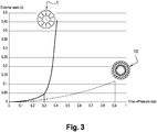
- the ordinate magnitude of the diagram is proportional to the overall strain of the structure 1.10, while the abscissa corresponds to the pressure imposed on said structure 1.10.
- the pressure necessary to deform the dielectric structure according to the invention, embodied by the dashed curve is much greater than that required to deform the electrical structure of the state of the art, embodied by the curve in FIG. Full line.
- the structure 1 "daisy" deforms from a pressure of 0.3
- the dielectric structure 10 according to the invention begins to deform only beyond a pressure 0.9, three times higher. This tends to show that a dielectric structure 10 according to the invention is at least three times more resistant to compression, a dielectric structure 1 of the "daisy” type of the state of the art.
Landscapes
- Insulating Bodies (AREA)
- Insulated Conductors (AREA)
Applications Claiming Priority (1)
| Application Number | Priority Date | Filing Date | Title |
|---|---|---|---|
| FR1150884A FR2971356B1 (fr) | 2011-02-03 | 2011-02-03 | Structure dielectrique resistant a la compression |
Publications (1)
| Publication Number | Publication Date |
|---|---|
| EP2485221A1 true EP2485221A1 (de) | 2012-08-08 |
Family
ID=44533440
Family Applications (1)
| Application Number | Title | Priority Date | Filing Date |
|---|---|---|---|
| EP12151756A Withdrawn EP2485221A1 (de) | 2011-02-03 | 2012-01-19 | Druckfeste dielektrische Struktur |
Country Status (5)
| Country | Link |
|---|---|
| US (1) | US20120199235A1 (de) |
| EP (1) | EP2485221A1 (de) |
| CN (1) | CN102629505A (de) |
| BR (1) | BR102012002416A2 (de) |
| FR (1) | FR2971356B1 (de) |
Families Citing this family (1)
| Publication number | Priority date | Publication date | Assignee | Title |
|---|---|---|---|---|
| EP3306740A1 (de) * | 2016-10-10 | 2018-04-11 | Rosenberger Hochfrequenztechnik GmbH & Co. KG | Dielektrisches wellenleiterkabel |
Citations (5)
| Publication number | Priority date | Publication date | Assignee | Title |
|---|---|---|---|---|
| FR2503441A1 (fr) * | 1981-04-07 | 1982-10-08 | Fabrication Cables Elect Cie G | Nouveau cable electrique |
| US5042904A (en) * | 1990-07-18 | 1991-08-27 | Comm/Scope, Inc. | Communications cable and method having a talk path in an enhanced cable jacket |
| US5990419A (en) * | 1996-08-26 | 1999-11-23 | Virginia Patent Development Corporation | Data cable |
| US20100175910A1 (en) * | 2009-01-14 | 2010-07-15 | General Cable Technologies Corporation | Jacket for cable data |
| WO2010095336A1 (ja) * | 2009-02-17 | 2010-08-26 | 宇部日東化成株式会社 | 差動伝送ケーブル用中空コア体の製造方法及び製造装置 |
Family Cites Families (4)
| Publication number | Priority date | Publication date | Assignee | Title |
|---|---|---|---|---|
| US1257337A (en) * | 1917-02-21 | 1918-02-26 | Carl Garvin | Interlocking tile-section. |
| US1677714A (en) * | 1924-12-29 | 1928-07-17 | Hurxthal F Frease | Tubular structure |
| US5569876A (en) * | 1993-05-17 | 1996-10-29 | Podgorski; Andrew S. | High voltage insulating structure |
| WO2009009747A1 (en) * | 2007-07-12 | 2009-01-15 | Adc Telecommunications, Inc. | Telecommunication wire with low dielectric constant insulator |
-
2011
- 2011-02-03 FR FR1150884A patent/FR2971356B1/fr not_active Expired - Fee Related
-
2012
- 2012-01-10 US US13/347,101 patent/US20120199235A1/en not_active Abandoned
- 2012-01-19 EP EP12151756A patent/EP2485221A1/de not_active Withdrawn
- 2012-02-02 BR BR102012002416-0A patent/BR102012002416A2/pt not_active Application Discontinuation
- 2012-02-03 CN CN2012100236034A patent/CN102629505A/zh active Pending
Patent Citations (5)
| Publication number | Priority date | Publication date | Assignee | Title |
|---|---|---|---|---|
| FR2503441A1 (fr) * | 1981-04-07 | 1982-10-08 | Fabrication Cables Elect Cie G | Nouveau cable electrique |
| US5042904A (en) * | 1990-07-18 | 1991-08-27 | Comm/Scope, Inc. | Communications cable and method having a talk path in an enhanced cable jacket |
| US5990419A (en) * | 1996-08-26 | 1999-11-23 | Virginia Patent Development Corporation | Data cable |
| US20100175910A1 (en) * | 2009-01-14 | 2010-07-15 | General Cable Technologies Corporation | Jacket for cable data |
| WO2010095336A1 (ja) * | 2009-02-17 | 2010-08-26 | 宇部日東化成株式会社 | 差動伝送ケーブル用中空コア体の製造方法及び製造装置 |
Also Published As
| Publication number | Publication date |
|---|---|
| BR102012002416A2 (pt) | 2014-01-07 |
| US20120199235A1 (en) | 2012-08-09 |
| FR2971356A1 (fr) | 2012-08-10 |
| FR2971356B1 (fr) | 2013-01-18 |
| CN102629505A (zh) | 2012-08-08 |
Similar Documents
| Publication | Publication Date | Title |
|---|---|---|
| EP1653574B1 (de) | Verfahren zur Montage eines elektrischen Verbinders auf ein Koaxialkabel und einen solchen Verbinder | |
| EP3993996B1 (de) | Schalldämmende beschichtung mit zellstruktur | |
| EP1340013A1 (de) | Flexible röhrenförmige leitung | |
| FR2808070A1 (fr) | Tube metallique flexible a caisson et conduite flexible comprenant un tel tube metallique | |
| EP2798644B1 (de) | Behälter für den transport und/oder die lagerung von radioaktivem material | |
| EP2320429B1 (de) | Verpackung für den Transport und/oder zur Zwischenlagerung radioaktiver Stoffe, die radial geschichtete Strahlenschutzelemente umfasst | |
| WO2015118401A1 (fr) | Gaine tubulaire annelée comportant un moyen intérieur de serrage | |
| EP1590862B1 (de) | Elektrischer verbinder | |
| EP2485221A1 (de) | Druckfeste dielektrische Struktur | |
| EP3302916B1 (de) | Hohlprofilelement wie z. b. ein rohr aus wärmehärtbarem verbundwerkstoff und entsprechendes verfahren | |
| EP2020365B1 (de) | Plattenelement, vorzugsweise in Profilform, insbesondere zur Bildung einer Seitenwand im Laderaum eines Fahrzeugs | |
| WO2005029649A2 (fr) | Dispositif de connexion pour panneaux conducteurs d’electricite | |
| EP2320432B1 (de) | Verpackung für den Transport und/oder zur Zwischenlagerung radioaktiver Stoffe, die eine verstärkte Wärmeübertragung ermöglicht | |
| EP3725200B1 (de) | Einsetzverfahren einer heizleitung in einen kühlkörper | |
| EP2461077B1 (de) | Befestigungsschelle für Rohre | |
| EP2850259A1 (de) | Bewehrungsstab mit verbessertem griff und verfahren zur herstellung davon | |
| WO2011070294A1 (fr) | Aube de turbine de turbomachine en composite a matrice ceramique avec evidements realises par usinage | |
| EP1753096A2 (de) | Führungsschienenanordnung für die elektrische Stromversorgungsanordnung mit bewegbarer Stromsteckdose | |
| FR2513449A1 (fr) | Procede et garniture de collier pour le ceinturage d'un faisceau d'elements, notamment de cables | |
| FR3017147A1 (fr) | Caisson pour boite d'attente et boite d'attente munie d'un tel caisson | |
| BE1008860A5 (fr) | Systeme de coffrage pour un ouvrage en beton. | |
| FR3001653A1 (fr) | Moule comprenant des coquilles et au moins un tiroir | |
| FR2626917A1 (fr) | Panneau de revetement, notamment d'isolation | |
| FR2704911A1 (fr) | Ensemble de construction, notamment pour meubles. | |
| FR2921857A1 (fr) | Paroi pour le moulage d'un materiau de construction |
Legal Events
| Date | Code | Title | Description |
|---|---|---|---|
| PUAI | Public reference made under article 153(3) epc to a published international application that has entered the european phase |
Free format text: ORIGINAL CODE: 0009012 |
|
| AK | Designated contracting states |
Kind code of ref document: A1 Designated state(s): AL AT BE BG CH CY CZ DE DK EE ES FI FR GB GR HR HU IE IS IT LI LT LU LV MC MK MT NL NO PL PT RO RS SE SI SK SM TR |
|
| AX | Request for extension of the european patent |
Extension state: BA ME |
|
| 17P | Request for examination filed |
Effective date: 20130208 |
|
| GRAP | Despatch of communication of intention to grant a patent |
Free format text: ORIGINAL CODE: EPIDOSNIGR1 |
|
| INTG | Intention to grant announced |
Effective date: 20140702 |
|
| RIC1 | Information provided on ipc code assigned before grant |
Ipc: H01B 7/02 20060101ALN20140623BHEP Ipc: H01B 11/02 20060101ALN20140623BHEP Ipc: H01B 7/18 20060101AFI20140623BHEP |
|
| STAA | Information on the status of an ep patent application or granted ep patent |
Free format text: STATUS: THE APPLICATION IS DEEMED TO BE WITHDRAWN |
|
| 18D | Application deemed to be withdrawn |
Effective date: 20141125 |