EP2020365B1 - Plattenelement, vorzugsweise in Profilform, insbesondere zur Bildung einer Seitenwand im Laderaum eines Fahrzeugs - Google Patents
Plattenelement, vorzugsweise in Profilform, insbesondere zur Bildung einer Seitenwand im Laderaum eines Fahrzeugs Download PDFInfo
- Publication number
- EP2020365B1 EP2020365B1 EP20080300241 EP08300241A EP2020365B1 EP 2020365 B1 EP2020365 B1 EP 2020365B1 EP 20080300241 EP20080300241 EP 20080300241 EP 08300241 A EP08300241 A EP 08300241A EP 2020365 B1 EP2020365 B1 EP 2020365B1
- Authority
- EP
- European Patent Office
- Prior art keywords
- panel
- wall
- shaped
- branch
- elementary
- Prior art date
- Legal status (The legal status is an assumption and is not a legal conclusion. Google has not performed a legal analysis and makes no representation as to the accuracy of the status listed.)
- Active
Links
Images

Classifications
-
- B—PERFORMING OPERATIONS; TRANSPORTING
- B62—LAND VEHICLES FOR TRAVELLING OTHERWISE THAN ON RAILS
- B62D—MOTOR VEHICLES; TRAILERS
- B62D33/00—Superstructures for load-carrying vehicles
- B62D33/04—Enclosed load compartments ; Frameworks for movable panels, tarpaulins or side curtains
- B62D33/044—Enclosed load compartments ; Frameworks for movable panels, tarpaulins or side curtains built up with profiles of constant elongated shape, e.g. extruded, mechanically interconnected by coupling members, e.g. by clamping, riveting or bolting
-
- B—PERFORMING OPERATIONS; TRANSPORTING
- B62—LAND VEHICLES FOR TRAVELLING OTHERWISE THAN ON RAILS
- B62D—MOTOR VEHICLES; TRAILERS
- B62D29/00—Superstructures, understructures, or sub-units thereof, characterised by the material thereof
- B62D29/008—Superstructures, understructures, or sub-units thereof, characterised by the material thereof predominantly of light alloys, e.g. extruded
-
- F—MECHANICAL ENGINEERING; LIGHTING; HEATING; WEAPONS; BLASTING
- F16—ENGINEERING ELEMENTS AND UNITS; GENERAL MEASURES FOR PRODUCING AND MAINTAINING EFFECTIVE FUNCTIONING OF MACHINES OR INSTALLATIONS; THERMAL INSULATION IN GENERAL
- F16B—DEVICES FOR FASTENING OR SECURING CONSTRUCTIONAL ELEMENTS OR MACHINE PARTS TOGETHER, e.g. NAILS, BOLTS, CIRCLIPS, CLAMPS, CLIPS OR WEDGES; JOINTS OR JOINTING
- F16B5/00—Joining sheets or plates, e.g. panels, to one another or to strips or bars parallel to them
- F16B5/0004—Joining sheets, plates or panels in abutting relationship
- F16B5/008—Joining sheets, plates or panels in abutting relationship by a rotating or sliding and rotating movement
Definitions
- the invention relates to an elementary panel advantageously shaped like a profile, in particular to form a side wall of a product loading space of a vehicle, by assembly with other elementary panels of this type, along its lengths. upper and lower longitudinal edges, by means of rapid snap locking means, the panel being formed by two walls, an inner wall and an outer wall, connected by spacer walls, the inner wall comprising one of its assembly longitudinal edges a male hook member and at its other longitudinal edge a complementary female hook member, so that these male and female hook members of a panel can cooperate with male and female hook elements of a another panel, a longitudinal edge of the outer wall being U-shaped opening outwardly and extending parallel to this wall and whose inner branch it is longer and L-shaped to have at its free end a perpendicular flange extending substantially to the level of the lower face of the wall, while the other longitudinal edge is configured so as to engage in a U of another panel and has a rib which extends inwardly of the panel and is intended to bear against the inner face of the flange of
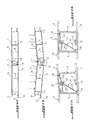
- FIG. 1A shows the assembly of two profiles of this type as is done for the realization of a side wall of a vehicle.
- the two walls bear the references 1a and 1b.
- the inner, outer and spacer walls of each profile are designated by the references 2, 3 and 4 respectively.
- the male hook element extending along an edge of the inner wall 2 is denoted 5 and the complementary hook element to the other edge of a panel is noted 6.
- the other longitudinal edge 15 of the wall 3 is configured to be received in the U-shaped edge 8 of another panel.
- the edge 15 of the panel 1b is received in the U-shaped edge 8 of the panel 1a.
- the end of the edge 15 is offset inward by a distance corresponding to the thickness of the wall 3, to bear against the inner face of the shorter outer leg 9 of the U 8.
- the edge comprises, at a distance from the end 16, the aforementioned rib noted 17, which, in the assembled state, as seen in the middle of the figure 1a , bears against the inner face of the flange 11 of the longer branch 10 of the U 8.
- the Figure 1B shows the behavior of the part of a wall formed by assembling the two panels 1a and 1b, under the effect of the forces F of a load, caused by products present in the loading space of the vehicle and exerting a pressure on the side wall of the vehicle.
- the L-shaped leg 10 at the edge of the outer wall 3 of the panel 1a flexes, with the result that the edge 15 of the panel 1b, which is locked in the U-shaped part 8 , in accordance with the Figure 1A can leave his home. This results in the rupture of the wall.
- the panels or profiles such as 1a and 1b are able to withstand charging pressures up to 5 Mtr. But when the load forces increase, the phenomenon illustrated in figure 1b , causing the rupture of the wall.
- a panel in the form of a profile is known from FR 1577610 A . This panel does not define hook elements of the type mentioned here.
- the object of the invention is to propose panels in the form of profiles, which overcome the drawback which has just been described of known panels.
- a profile according to the invention is characterized in that the assembly edges are provided with means for reinforcing the bending resistance of the L-shaped locking leg.
- the panel is characterized in that the reinforcing means is formed by a support piece of the aforementioned locking leg.
- the elementary panel is characterized in that the support part comprises a support part of the elbow of the L-shaped limb and two support legs of the part which are supported by their end on the faces. inner and outer walls.
- the elementary panel is characterized in that the means for reinforcing the L-shaped branch comprises a support wall of the L-shaped branch which extends between the branch and the inner face facing each other. of the inner wall of the panel.
- the elementary panel is characterized in that the means for reinforcing the bending strength of the L-shaped locking leg comprises a bar which extends parallel to the edge of the wall. end and cooperates with a bearing heel on the inner surface of the outer wall of the panel.
- the elementary panel is characterized in that the panel is in the form of a profile.
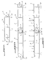
- the first embodiment of the invention uses panels advantageously in the form of known profiles as shown in FIGS. Figures 1A and 1B and eliminates the problem of unlocking the profiles under the effect of too high load forces, by insertion between the two section ends to be locked of an additional support member designated by the reference 20.
- This support member 20 has an intermediate support portion 21 which abuts against the bent portion 27 of the L-shaped branch 10 and two legs supporting the support portion 21 whose free ends bear on internal faces of the angles 25, 26 of the two diagonally opposite sections 1a, 1b, to prevent, through the part 21, the support of the elbow 27 of the U locking profile 1a, the flexion of the branch 10.
- the support piece 20 is inserted before assembly and takes the final position according to the Figure 2A when the two sections are locked towards each other, at their ends.
- FIGS. 3A, 3B, 3C illustrate a second embodiment of the invention according to which the problem of unlocking the sections under the effect of too large loads is solved by providing on the branch 10 in the form of an L, of the locking U 8, an additional bar 28, which is parallel to the perpendicular flange 11 and located therebetween and the birth of the branch.
- On the complementary locking end 15 is provided a heel 30 which protrudes from the inner face of the wall 3, and is arranged so that the bar 28 is placed in the assembled state of the two sections, between the rib 17 and the heel 30, as seen on the figure 3B and bears against the heel when load forces F apply against the inner face of the side wall obtained by assembling profiles according to the invention.
- the bar 28 is provided at its free end with a small hook 29 intended to cooperate with a complementary element on the heel 30 in order to ensure a good hold of the system.
- both the bar 28 and the heel 30 extend over the entire length of the assembly edge.
- the Figures 4A and 4B show a third embodiment. This provides a particular configuration of the longitudinal assembly edge of the profiles 1, which has the locking portion having the general shape of a U, with the inner leg 10 longer L. L-shaped part and the branch on the Figures 4A and 4B the references respectively 8 ', 10', the rim being denoted 11 '.
- the assembly edge comprises a spacer wall 32 advantageously inclined at an angle of 45 ° with respect to the spacer walls 4 of the profiles according to the first two embodiments. and which extends from the inner wall 2 to the L-branch 10 'by connecting thereto at a location 33 relatively close to the flange 11'.
- the edge 15 engaging in the U-shaped portion 8 ' has the configuration of the known profiles. This is also the case for the male and female locking elements 5 and 6 at the inner wall of the profiles.
- the spacer wall near the assembly edge having the edge 15 is also inclined with respect to the orthogonal direction of the walls, but at an angle less than 45 °.
- FIGS 4B, 4C illustrate two different moments of the assembly process of the two sections shown 1a, 1b.
Landscapes
- Engineering & Computer Science (AREA)
- Mechanical Engineering (AREA)
- General Engineering & Computer Science (AREA)
- Chemical & Material Sciences (AREA)
- Combustion & Propulsion (AREA)
- Transportation (AREA)
- Architecture (AREA)
- Structural Engineering (AREA)
- Connection Of Plates (AREA)
- Body Structure For Vehicles (AREA)
Claims (6)
- Plattenelement, vorzugsweise in Profilform, insbesondere zur Bildung einer Seitenwand im Produktladeraum eines Fahrzeugs, durch Verbindung mit anderen Plattenelementen dieser Bauart entlang seiner oberen und unteren Längsverbindungsränder mit Hilfe von Schnellverriegelungsmittel durch Einrasten, wobei die Platte von zwei Wänden gebildet wird, einer Innenwand (2) und einer Außenwand (3), die durch Querstrebwände (4) verbunden sind, wobei die Innenwand an einem ihrer Längsverbindungsränder ein männliches Hakenelement (5) und an ihrem anderen Längsrand ein komplementäres weibliches Hakenelement (6) derart umfasst, dass diese männlichen und weiblichen Hakenelemente einer Platte mit den männlichen und weiblichen Hakenelementen einer anderen Platte zusammenarbeiten können, wobei ein Längsrand der Außenwand in Form eines sich nach außen öffnenden U (8) ist und sich parallel zu dieser Wand erstreckt und dessen Innenschenkel (10) länger ist und in Form eines L, um an seinem freien Ende einen senkrechten Endumschlag (11) aufzuweisen, der sich nach außen erstreckt, wogegen der andere Längsrand (15) derart konfiguriert ist, dass er in ein U einer anderen Platte eingreift und eine Rippe (17) aufweist, die sich nach innen zur Wand erstreckt und dazu bestimmt ist, sich auf der Innenseite des Aufnahmeumschlags des U der anderen Platte abzustützen, dadurch gekennzeichnet, dass die Verbindungsränder mit Mitteln (20; 28, 30; 32) zur Verstärkung des Biegewiderstands des L-förmigen Verriegelungsschenkels (10) ausgestattet sind.
- Plattenelement nach Anspruch 1, dadurch gekennzeichnet, dass das Verstärkungsmittel von einem Stützteil (20) des vorgenannten Verriegelungsschenkels (10) gebildet wird.
- Plattenelement nach Anspruch 2, dadurch gekennzeichnet, dass das Stützteil (20) einen Stützabschnitt (21) der Krümmung des L-förmigen Schenkels (10) aufweist und zwei Stützbeine (22, 23) des Abschnitts (21), die sich mit ihrem Ende auf den Innenseiten der Innenwand (2) und der Außenwand (3) abstützen.
- Plattenelement nach Anspruch 1, dadurch gekennzeichnet, dass das Verstärkungsmittel des L-förmigen Schenkels (10) ein Stützwand (32) des L-förmigen Schenkels (10) aufweist, die sich zwischen dem Schenkel (10) und der Innenseite gegenüber der Innenwand (2) der Platte erstreckt.
- Plattenelement nach Anspruch 1, dadurch gekennzeichnet, dass das Verstärkungsmittel des Biegewiderstands des L-förmigen Verriegelungsschenkels (10) einen Steg (28) aufweist, der sich parallel zum Endumschlag (11) erstreckt und mit einer Stützferse (30) auf der Innenseite der Außenwand (3) der Platte zusammenarbeitet.
- Plattenelement nach einem der vorangehenden Ansprüche, dadurch gekennzeichnet, dass die Platte in Profilform ist.
Applications Claiming Priority (1)
| Application Number | Priority Date | Filing Date | Title |
|---|---|---|---|
| FR0756734A FR2919374B1 (fr) | 2007-07-25 | 2007-07-25 | Panneau elementaire avantageusement en forme d'un profile, notamment pour former une paroi laterale d'un espace de chargement de produits d'un vehicule. |
Publications (2)
| Publication Number | Publication Date |
|---|---|
| EP2020365A1 EP2020365A1 (de) | 2009-02-04 |
| EP2020365B1 true EP2020365B1 (de) | 2011-06-08 |
Family
ID=39129024
Family Applications (1)
| Application Number | Title | Priority Date | Filing Date |
|---|---|---|---|
| EP20080300241 Active EP2020365B1 (de) | 2007-07-25 | 2008-07-21 | Plattenelement, vorzugsweise in Profilform, insbesondere zur Bildung einer Seitenwand im Laderaum eines Fahrzeugs |
Country Status (2)
| Country | Link |
|---|---|
| EP (1) | EP2020365B1 (de) |
| FR (1) | FR2919374B1 (de) |
Families Citing this family (5)
| Publication number | Priority date | Publication date | Assignee | Title |
|---|---|---|---|---|
| BE1019421A3 (nl) * | 2010-07-13 | 2012-07-03 | Cnh Belgium Nv | Graantankdeksel voor een maaidorser. |
| DE102013100215A1 (de) * | 2013-01-10 | 2014-07-10 | F. Hesterberg & Söhne Gmbh & Co. Kg | verschließbare Türanordnung für einen Nutzfahrzeugaufbau |
| CN111619673A (zh) * | 2019-02-28 | 2020-09-04 | 晟通科技集团有限公司 | 箱体底架 |
| CN114313029B (zh) * | 2021-12-27 | 2024-07-26 | 江西日菱车业有限公司 | 一种车厢板及其生产工艺 |
| CH722035A1 (de) * | 2024-08-12 | 2026-02-27 | Uster Technologies Ag | Mehrteiliges gehäuse für eine vorrichtung |
Family Cites Families (4)
| Publication number | Priority date | Publication date | Assignee | Title |
|---|---|---|---|---|
| DE1974448U (de) * | 1967-09-14 | 1967-12-07 | Metall Werk Mekur G M B H | Aus kastenprofilen zusammengesetzte, einseitig belastbare wand od. dgl. |
| DE1945687A1 (de) * | 1969-09-10 | 1971-03-25 | Ver Deutsche Metallwerke Ag | Bordwand fuer Pritschenfahrzeuge |
| AT370047B (de) * | 1981-02-13 | 1983-02-25 | Vmw Ranshofen Berndorf Ag | Aus strangpressprofilen, die mit randseitigen laengsrippen kraftschluessig ineinandergreifen, gebildete platte od.dgl. |
| FR2703114A1 (fr) * | 1993-03-24 | 1994-09-30 | Trouillet Sa Atelier Carrosser | Dispositif d'assemblage d'au moins deux plaques, notamment en tôle mince. |
-
2007
- 2007-07-25 FR FR0756734A patent/FR2919374B1/fr not_active Expired - Fee Related
-
2008
- 2008-07-21 EP EP20080300241 patent/EP2020365B1/de active Active
Also Published As
| Publication number | Publication date |
|---|---|
| FR2919374A1 (fr) | 2009-01-30 |
| EP2020365A1 (de) | 2009-02-04 |
| FR2919374B1 (fr) | 2009-10-23 |
Similar Documents
| Publication | Publication Date | Title |
|---|---|---|
| EP2598785B1 (de) | Klemmsystem zur verbindung und vormontage eines ersten und zweiten rohrs | |
| EP2502017B1 (de) | Kollektorbox und mit einer derartigen box ausgestatteter wärmetauscher | |
| EP2201870B1 (de) | Druckkochgerät zum Zubereiten von Nahrungsmitteln mit Verschlussklammern mit vermindertem Gewicht und Herstellungsverfahren | |
| EP3140604B1 (de) | Kopf für einen wärmetauscher eines kraftfahrzeugs | |
| FR2885102A1 (fr) | Connecteur reliant un balai d'essuie-glasse a un bras d'entrainement | |
| FR3043500B1 (fr) | Element de contact pour une liaison de connexion | |
| FR2968366A1 (fr) | Clip de fixation elastique. | |
| EP2020365A1 (de) | Plattenelement, vorzugsweise in Profilform, insbesondere zur Bildung einer Seitenwand im Laderaum eines Fahrzeugs | |
| EP3901507B1 (de) | Spannsystem für die verbindung von rohren, das eine schelle und eine unterlegscheibe mit haltebügeln umfasst | |
| EP1590862B1 (de) | Elektrischer verbinder | |
| EP3112227A1 (de) | Adapter zum verbinden eines scheibenwischers mit einem antriebsarm | |
| EP3781890B1 (de) | Sammelbehälter und zubehöriger wärmetauscher | |
| EP0799952A1 (de) | Vorrichtung zum Zusammenbau vorgefertigter Paneelen für eine Schwimmbadwand und dadurch hergestellte Schwimmbadwand | |
| FR2549915A1 (fr) | Perfectionnements aux systemes de vissage comprenant un ecrou a embase et aux composants de ces systemes | |
| EP3081719A1 (de) | Verbindungsprofil für ein abdeckelement, insbesondere für teleskopabdeckung eines schwimmbads | |
| FR3108960A1 (fr) | Système de serrage pour le raccordement de tubes, comprenant un collier et une rondelle portant des pattes de support | |
| EP3795877B1 (de) | Schlauchklemme | |
| FR2884582A1 (fr) | Dispositif pour l'accouplement etanche de deux tubes lisses | |
| EP0675989B1 (de) | Vorrichtung zur verbindung von zwei profilen und männliche und/oder weibliche profile | |
| EP2055883B1 (de) | Verfahren zur Herstellung einer Baustrebe durch Crimpen, und so erhaltene Baustrebe | |
| EP2389324B1 (de) | Vorrichtung zum zusammenfügen von ein kochwerkzeug definierenden komponenten | |
| BE1026538A1 (fr) | Accessoire de fixation d'un panneau de grillage a un poteau de clôture comportant une piece de blocage et une piece de serrage | |
| FR3054653A1 (fr) | Plaque collectrice, boite collectrice et echangeur thermique correspondants | |
| FR2732083A1 (fr) | Dispositif de connexion a montage simplifie pour assembler deux profiles | |
| EP2570566A2 (de) | Fugenabdeckungsvorrichtung für Bodenbelag |
Legal Events
| Date | Code | Title | Description |
|---|---|---|---|
| PUAI | Public reference made under article 153(3) epc to a published international application that has entered the european phase |
Free format text: ORIGINAL CODE: 0009012 |
|
| AK | Designated contracting states |
Kind code of ref document: A1 Designated state(s): AT BE BG CH CY CZ DE DK EE ES FI FR GB GR HR HU IE IS IT LI LT LU LV MC MT NL NO PL PT RO SE SI SK TR |
|
| AX | Request for extension of the european patent |
Extension state: AL BA MK RS |
|
| 17P | Request for examination filed |
Effective date: 20090723 |
|
| 17Q | First examination report despatched |
Effective date: 20090819 |
|
| AKX | Designation fees paid |
Designated state(s): CH DE FR LI |
|
| GRAP | Despatch of communication of intention to grant a patent |
Free format text: ORIGINAL CODE: EPIDOSNIGR1 |
|
| GRAS | Grant fee paid |
Free format text: ORIGINAL CODE: EPIDOSNIGR3 |
|
| GRAA | (expected) grant |
Free format text: ORIGINAL CODE: 0009210 |
|
| AK | Designated contracting states |
Kind code of ref document: B1 Designated state(s): CH DE FR LI |
|
| REG | Reference to a national code |
Ref country code: CH Ref legal event code: EP |
|
| REG | Reference to a national code |
Ref country code: DE Ref legal event code: R096 Ref document number: 602008007400 Country of ref document: DE Effective date: 20110721 |
|
| REG | Reference to a national code |
Ref country code: CH Ref legal event code: NV Representative=s name: TROESCH SCHEIDEGGER WERNER AG |
|
| REG | Reference to a national code |
Ref country code: CH Ref legal event code: PUE Owner name: POMMIER Free format text: POMMIER GROSS ALUMINIUM GMBH#IN DER GROBACH 18#61197 FLORSTADT (DE) -TRANSFER TO- POMMIER#7, AVENUE DE LA MARE Z.A. DES BETHUNES#95310 SAINT-OUEN L'AUMONE (FR) |
|
| REG | Reference to a national code |
Ref country code: FR Ref legal event code: TP Owner name: POMMIER, FR Effective date: 20120216 |
|
| REG | Reference to a national code |
Ref country code: DE Ref legal event code: R082 Ref document number: 602008007400 Country of ref document: DE Representative=s name: PATENTANWAELTE RUFF, WILHELM, BEIER, DAUSTER &, DE |
|
| PLBE | No opposition filed within time limit |
Free format text: ORIGINAL CODE: 0009261 |
|
| STAA | Information on the status of an ep patent application or granted ep patent |
Free format text: STATUS: NO OPPOSITION FILED WITHIN TIME LIMIT |
|
| 26N | No opposition filed |
Effective date: 20120309 |
|
| REG | Reference to a national code |
Ref country code: DE Ref legal event code: R082 Ref document number: 602008007400 Country of ref document: DE Representative=s name: PATENTANWAELTE RUFF, WILHELM, BEIER, DAUSTER &, DE Effective date: 20120402 Ref country code: DE Ref legal event code: R081 Ref document number: 602008007400 Country of ref document: DE Owner name: POMMIER, FR Free format text: FORMER OWNER: POMMIER GROSS ALUMINIUM GMBH, 61197 FLORSTADT, DE Effective date: 20120402 |
|
| REG | Reference to a national code |
Ref country code: DE Ref legal event code: R097 Ref document number: 602008007400 Country of ref document: DE Effective date: 20120309 |
|
| REG | Reference to a national code |
Ref country code: DE Ref legal event code: R082 Ref document number: 602008007400 Country of ref document: DE Representative=s name: PATENTANWAELTE RUFF, WILHELM, BEIER, DAUSTER &, DE |
|
| REG | Reference to a national code |
Ref country code: DE Ref legal event code: R082 Ref document number: 602008007400 Country of ref document: DE Representative=s name: PATENTANWAELTE RUFF, WILHELM, BEIER, DAUSTER &, DE Effective date: 20140325 Ref country code: DE Ref legal event code: R081 Ref document number: 602008007400 Country of ref document: DE Owner name: POMMIER, FR Free format text: FORMER OWNER: POMMIER, SAINT QUEN L'AUMONE, FR Effective date: 20140325 |
|
| REG | Reference to a national code |
Ref country code: FR Ref legal event code: PLFP Year of fee payment: 9 |
|
| PGFP | Annual fee paid to national office [announced via postgrant information from national office to epo] |
Ref country code: CH Payment date: 20160727 Year of fee payment: 9 |
|
| REG | Reference to a national code |
Ref country code: FR Ref legal event code: PLFP Year of fee payment: 10 |
|
| REG | Reference to a national code |
Ref country code: CH Ref legal event code: PL |
|
| PG25 | Lapsed in a contracting state [announced via postgrant information from national office to epo] |
Ref country code: CH Free format text: LAPSE BECAUSE OF NON-PAYMENT OF DUE FEES Effective date: 20170731 Ref country code: LI Free format text: LAPSE BECAUSE OF NON-PAYMENT OF DUE FEES Effective date: 20170731 |
|
| REG | Reference to a national code |
Ref country code: FR Ref legal event code: PLFP Year of fee payment: 11 |
|
| PGFP | Annual fee paid to national office [announced via postgrant information from national office to epo] |
Ref country code: DE Payment date: 20190930 Year of fee payment: 12 |
|
| REG | Reference to a national code |
Ref country code: DE Ref legal event code: R119 Ref document number: 602008007400 Country of ref document: DE |
|
| PG25 | Lapsed in a contracting state [announced via postgrant information from national office to epo] |
Ref country code: DE Free format text: LAPSE BECAUSE OF NON-PAYMENT OF DUE FEES Effective date: 20210202 |
|
| P01 | Opt-out of the competence of the unified patent court (upc) registered |
Effective date: 20230518 |
|
| PGFP | Annual fee paid to national office [announced via postgrant information from national office to epo] |
Ref country code: FR Payment date: 20250710 Year of fee payment: 18 |