EP2485237A1 - Commutateur de protection du courant contre l'erreur - Google Patents
Commutateur de protection du courant contre l'erreur Download PDFInfo
- Publication number
- EP2485237A1 EP2485237A1 EP11195006A EP11195006A EP2485237A1 EP 2485237 A1 EP2485237 A1 EP 2485237A1 EP 11195006 A EP11195006 A EP 11195006A EP 11195006 A EP11195006 A EP 11195006A EP 2485237 A1 EP2485237 A1 EP 2485237A1
- Authority
- EP
- European Patent Office
- Prior art keywords
- circuit breaker
- current circuit
- residual current
- switching
- lever
- Prior art date
- Legal status (The legal status is an assumption and is not a legal conclusion. Google has not performed a legal analysis and makes no representation as to the accuracy of the status listed.)
- Granted
Links
Images


Classifications
-
- H—ELECTRICITY
- H01—ELECTRIC ELEMENTS
- H01H—ELECTRIC SWITCHES; RELAYS; SELECTORS; EMERGENCY PROTECTIVE DEVICES
- H01H71/00—Details of the protective switches or relays covered by groups H01H73/00 - H01H83/00
- H01H71/10—Operating or release mechanisms
- H01H71/50—Manual reset mechanisms which may be also used for manual release
- H01H71/52—Manual reset mechanisms which may be also used for manual release actuated by lever
- H01H71/526—Manual reset mechanisms which may be also used for manual release actuated by lever the lever forming a toggle linkage with a second lever, the free end of which is directly and releasably engageable with a contact structure
-
- H—ELECTRICITY
- H01—ELECTRIC ELEMENTS
- H01H—ELECTRIC SWITCHES; RELAYS; SELECTORS; EMERGENCY PROTECTIVE DEVICES
- H01H83/00—Protective switches, e.g. circuit-breaking switches, or protective relays operated by abnormal electrical conditions otherwise than solely by excess current
- H01H83/02—Protective switches, e.g. circuit-breaking switches, or protective relays operated by abnormal electrical conditions otherwise than solely by excess current operated by earth fault currents
Definitions
- the invention relates to a residual current circuit breaker for detecting fault currents, which has at least one switching contact, which is opened when a fault current occurs by means of a switching mechanism of the residual current circuit breaker.
- the residual current circuit breaker on a trip relay with a movably mounted release plunger which is moved in the occurrence of a fault current from a starting position in a tripped position.
- the switching mechanism is kinematically coupled to the release plunger.
- the residual current circuit breaker on a rotatably mounted application lever to return the release plunger from the released position back to the starting position.
- a residual current circuit breaker is a protective device to ensure protection against a dangerous fault current in an electrical system.
- a fault current which is also referred to as differential current, occurs when a live line part has an electrical contact with earth. This is for example the case when a person touches a live part of an electrical system: in this case, the current flows as a fault current through the body of the person against the ground.
- the electrical system quickly and safely disconnect all poles from the mains.
- the terms residual current circuit breaker (RCD) or RCD (Residual Current Protective Device) are also used equivalently.
- the differential current is determined with the aid of a so-called summation current transformer, which adds all the currents flowing to and from an electrical load with the correct sign. If a current is diverted to earth at any point in the circuit, the sum of currents flowing back and forth in the summation current transformer is not equal to zero. The determined current difference then leads to the triggering of the residual current circuit breaker and thus to the shutdown of the power supply in the relevant circuit. Since the differential currents determined are usually comparatively small, they also have only a low energy density. Therefore, the fault current can not, for example, in a circuit breaker, directly for triggering a switching mechanism, for example by means of a magnetic coil and a shock absorber in the event of a short-circuit release, can be used. Instead, a trip relay is usually used, which, however, has only a comparatively low release force because of the usually small residual current. Due to the low tripping energy such tripping relays therefore react comparatively sensitive to shocks and / or vibrations.
- the residual current circuit breaker according to the invention is designed to detect fault currents and has a tripping relay, with a tripping plunger, which is moved on the occurrence of a fault current from a starting position to a tripped position. Furthermore, the residual current circuit breaker has a switching mechanism which is kinematically coupled to the release plunger such that when a fault current occurs, a switching contact coupled to the switching mechanism is opened, as well as a rotatably mounted apply lever to move the trigger plunger via a restoring force from the released position in the Reset initial position.
- the application lever is held in closed position by the switching mechanism against the restoring force in a first position and released when triggering the residual current circuit breaker of the switching mechanism, wherein the application lever is kinematically coupled to the switching mechanism that when triggering the residual current circuit breaker arranged on the switching mechanism control slides on a trained as a control cam portion of the Anlegehebels along until the landing lever is released.
- the interaction of the arranged on the switching mechanism control with the trained as a control cam portion of the Anlegehebels represents a cam control.
- This has the advantage that the coupling of the switching mechanism with the Anlegehebel has a freewheel: in a highly dynamic triggering operation, the control of the switching mechanism runs along the control curve under the Anlegehebel away until it is free, ie Control and control cam are no longer in contact with each other.
- the apply lever is now no longer held in the first position and is thus rotatable, so that the restoring force, the rotation of the apply lever can cause the return of the trigger plunger from its tripped position to its original position.
- the control is formed on a rotatably mounted switching shaft of the switching mechanism and cooperates with the control cam so that when triggering the residual current circuit breaker, the switching shaft is rotated to open the switching contact and release the application lever, and when closing the switching contact of the contact lever is moved by a rotation of the shift shaft in the first position and held there.
- the arrangement of the control on the switching shaft of the residual current circuit breaker provides a simple way to Constructive implementation of the cam control, ie the interaction of the control with the control cam of the docking lever, is an additional mechanical coupling of the docking lever to the switching mechanism - for example via a drawbar or a linkage - is not required, whereby the number of parts can be reduced and the assembly costs can be reduced ,
- control cam interacts with the control element formed on the selector shaft such that the contact lever reaches its first position already within a first rotational angle range of the selector shaft when the switch contact closes.
- the size of the first rotation angle range is characterized by the structural design of the cam control, i. adjustable by the shape of the control cam and the control and their interaction.
- the first rotation angle range of the switching shaft is approximately 15 ° to 20 °.
- the mechanical spring is designed as a torsion spring.
- a torsion spring provides a simple and cost-effective way to apply the restoring force for the rotational movement of the docking lever.
- a contact region of the control element with the control cam is pressurized.
- the application lever has a bayonet contour for safe storage of the application lever. With the help of the bayonet contour of the application lever is secured to a journal of the residual current circuit breaker in the axial direction against unintentional disassembly. The reliability of the residual current circuit breaker is thereby further improved.
- a fault current circuit breaker for example, be formed 4-pin: this includes, inter alia, a switching mechanism, a trip relay and four switching contacts (for Unterberechung the three phase lines and the neutral conductor) on. Since the movement of the application lever is kinematically decoupled from the highly dynamic movement of the switching mechanism or the selector shaft, a change in the number of poles of the residual current circuit breaker to be switched does not affect the restoring force for resetting the trigger plunger.
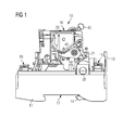
- FIG. 1 the fault current circuit breaker 10 according to the invention is shown schematically in a side view.
- the residual current circuit breaker 10 has a housing 11 with a front side 16 and a rear side 17 arranged opposite the front side 16.
- an operating element 12 for manual operation of the residual current circuit breaker 10 is formed.
- a mounting rail (not shown) are attached.
- a movable locking element 14 is arranged for engaging behind the support rail on the housing 11, which is manually operable to release the residual current circuit breaker 10 of the support rail via a slider 13.
- the residual current circuit breaker 10 has a switching contact (not shown) with a relative to the housing 11 fixedly arranged contact piece and a relatively movable contact piece.
- the switching contact is opened by means of a switching mechanism of the residual current circuit breaker 10.
- the movable contact piece of the switch contact is kinematically coupled to a rotatably mounted in the housing 11 shift shaft 30 of the switching mechanism, that the switching contact 30 is opened or closed by a rotational movement of the switching shaft.
- the residual current circuit breaker 10 a trip relay 20 with a movably mounted Trigger plunger 21, which is also kinematically coupled to the switching mechanism.
- the tripping relay 21 is moved from a starting position to a tripped position via the tripping relay 20, whereby the switching mechanism of the residual current circuit breaker 10 is triggered and the switching contact is opened.
- the residual current circuit breaker 10 has a so-called application lever 40, which is rotatably mounted in the housing 11.
- the residual current circuit breaker 10 may also have a plurality of switching contacts, all of which can be actuated by means of the switching mechanism of the residual current circuit breaker 10.
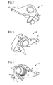
- FIG. 2 the landing lever 40 according to the invention is shown schematically in several perspective views.
- the application lever 40 has a bearing bore 44, via which it in the mounted state on a housing 11 formed on the journal 18 (see FIGS. 3A and 3B ) is rotatably mounted. With the help of a trained on Anlegehebel 40, arcuate bayonet contour 43, the storage of the landing lever 40 is secured to the bearing pin 18 in the axial direction.
- an actuating surface 45 is formed for returning the release plunger 21 from the released position to the starting position.
- a mounting snaphook 52 is eye-shaped on the application lever 40, which for securing the application lever 40 during assembly to a latching edge 53 (see FIGS. 4A to 4D ) of the residual current circuit breaker 10 can be latched.
- the application lever 40 has a cam 41 formed on a pin-like projection 48.
- the outer surface of the bearing bore 44 is formed as a bearing mandrel 46 for receiving and supporting a contact spring 42.
- the application spring 42 is designed as a torsion spring and serves to provide the required to reset the release plunger 21 restoring force. Since the restoring force of the Applying spring 42 is provided, it is possible to kinematically decouple the return movement of the engaging lever 40 from the highly dynamic rotational movement of the switching shaft 30, as occurs when opening the switching contact or the switching contacts of the residual current circuit breaker 10. The restoring force is thus independent of the contact force of the switch contacts and regardless of the number of poles or the number of switching contacts of the residual current circuit breaker 10. In this way, a gentle, largely shock-free resetting of the trigger plunger 21 in its initial position by a gentle rotational movement of the landing lever 40 allows.
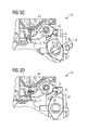
- FIGS. 3A to 3D is the interaction of the switching mechanism with the application lever 40 during various switching states of the residual current circuit breaker 10 - each in a side view - shown schematically.
- FIG. 3A an OFF position of the residual current circuit breaker 10 is shown.
- the switching contact is open, the switching shaft 30 with the movable contact piece coupled thereto is in an open position corresponding to the OFF position.
- the movable contact piece and the stationarily arranged contact piece of the switching contact are not in contact with each other, so that no current flows through the switching contact.
- the OFF position of the residual current circuit breaker 10 of the application lever 40 with its actuating surface 45 on so-called ram plate 22 of the trip relay 20 at.
- the ram plate 22 is fixed to a lower end of the release ram 21. Due to the restoring force applied by the torque of the application spring 42, the actuation surface 45 of the application lever 40 bears against the plunger plate 22 with a constant force, so that false triggering of the release relay 20 is prevented from the outset due to vibrations.
- FIG. 3B shows the interaction of the switching shaft 30 with the application lever 40 during a switch-on of the residual current circuit breaker 10.
- the actuator 12 see Fig. 1
- the switching shaft 30 is thereby counter-clockwise rotated in rotation.
- the formed on the cam 32 of the shift shaft 30 control member 31 formed on the Anformung 48 of the Anlegehebels 40 control cam 41.
- the pin-like Anformung 48 driven by the cam 32, so that the application lever 40 is also offset in the counterclockwise direction in a rotary motion.
- the kinematic interaction of the control element 31 with the control cam 41 is carried out by a corresponding shaping of the control element 31 and / or the control curve 41 such that the application lever 40 its complete stroke, ie its complete rotational movement, which is required to the release plunger 21 with to reset the desired force, already within a first rotational angle range ⁇ of the shift shaft 30 performs.
- the application lever 40 thus reaches its first position already at an early point in time, even before the switching contact is closed by the further rotation of the switching shaft 30 by a further rotation angle range ⁇ (see FIG Fig. 3C ).
- This has the advantage that the application lever 40 is already in its first position when the residual current circuit breaker 10 is switched on and is therefore "ready", even if a fault current occurs Immediately after switch-on.
- the size of the first rotation angle range ⁇ is also adjustable by the structural design of the cam control, ie by the shape of the control cam 41 and the control element 31 and their interaction.
- FIG. 3C is the switching shaft 30 in a position in which the switching contact is closed. Since the control cam 41 of the application lever 40 is formed flatter in this area, the rotational movement of the shift shaft 30 in the further rotation angle range ⁇ has no noticeable effect on the rotational position of the application lever 40. Since the application lever 40 its first position within the first rotation angle range ⁇ of Switching shaft 30 has reached, the further rotation angle range ⁇ of the shift shaft 30 thus only leads to the closing of the switch contact.
- FIG 3D the fault current circuit breaker 10 is shown in its tripped position as it occurs after tripping of the residual current circuit breaker 10 due to a fault current. If a fault current is detected, this leads to a tripping of the tripping relay 20 and thus to a movement of the tripping plunger 21. In this way, the switching mechanism of the residual current circuit breaker 10 is actuated, whereby a highly dynamic shutdown is initiated. In this case, the switching contact of the residual current circuit breaker 10 is opened by a rotational movement of the switching shaft 30 in a clockwise direction, whereby the current flow is interrupted via the switching contact. The shift shaft 30 is doing in their in Fig. 3D shown OFF position moves.
- the highly dynamic tearing movement of the shift shaft 30 is not transmitted to the application lever 40.
- the highly dynamic tearing movement of the cam 42 of the shift shaft 30 passes under the formed on the Anformung 48 cam 41 away until the contact between the control cam 42 and the control member 31 is interrupted, whereby the application lever 40 is released for its rotational movement.
- the trip relay 20 is thereby protected from shocks and / or shocks, as they can be caused by the highly dynamic tearing movement of the switching shaft 30 to open the switch contact.
- FIGS. 4A to 4E the sequence of mounting the landing lever 40 according to the invention is shown schematically - each in a side view of the residual current circuit breaker 10 - in several assembly steps.
- FIG. 4A is shown a position for attaching the docking lever 40.
- the application lever 40 is used together with the pre-mounted on the bearing mandrel 46 apply spring 42 (see FIG. 2 ) in the FIG. 4A shown position with its bearing bore 44 mounted on the formed in an inner wall 19 of the residual current circuit breaker 10 bearing pin 18.
- the bayonet contour 43 of the docking lever 40 is not yet engaged.
- a spring leg 49 of the application spring 42 which later rests against a housing contour of the housing 11 of the residual current circuit breaker 10 to exert the restoring force on the application lever 40 is still free.
- the actuating surface 45 for resetting the trigger plunger 21 on the plunger plate 22 is located at the beginning of the installation of the application lever 40 in the space of the trip relay 20. An assembly of the trip relay 20 is therefore only after the installation of the docking lever 40th possible. When mounted trip relay 20 thereby disassembly of the docking lever 40 is no longer possible.
- FIG. 4C the application lever 40 is shown in a position in which the bayonet contour 43 already partially engages behind a projection 51 formed in the inner wall 19 and is therefore already partly covered by the projection 51.
- the application lever 40 is secured in this rotational position against axial detachment from the bearing pin 18.
- the bayonet contour 43 permanently engages behind this projection 51 at least partially.
- a further axial securing of the application lever 40, for example by a cover plate, is therefore no longer necessary.
- the bearing pin 18 for supporting the landing lever 40 requires no further support and is designed as a flying journal.
- a trained on Anlegehebel 40 mounting snap hook 52 is about to latch with the formed on the inner wall 19 locking edge 53rd
- FIG. 4D shows the application lever 40 in a locked position of the mounting snap hook 52.
- the mounting snap hook 52 is latched to the locking edge 53, so that the application lever 40 can not be rotated in the clockwise direction.
- FIG. 4A shown mounting position for attaching the application lever 40 is moved to the bearing pin 18. This ensures that the bayonet contour 43 remains permanently engaged and the application lever 40 is thus secured against axial movement on the bearing journal 18.
- the assembly process is significantly simplified.
- the mounting snap hook 52 is shaped such that a release of the latching connection of the mounting snap hook 52 is possible at the locking edge 53 only by a manual pushing away of the mounting snap hook 52.
- FIG. 4E the position of the docking lever 40 during assembly of the trip relay 20 is shown.
- the apply lever 40 is moved over its first position (see FIGS. 3B and 3C ) into the in Figure 4E shown rotated position.
- the actuating surface 45 of the Anlegehebels 40 for resetting the trigger plunger 21 is far away from the trip relay 20 and releases the necessary space for mounting the trip relay 20 space. This is necessary because the trip relay 20 has at its lower end a hook 24 for limiting the plunger stroke of the trigger plunger 21.
- the Figure 4E illustrated position of the apply lever 40 represents an end position for a rotation of the apply lever counterclockwise, which is limited by a formed on the housing 11 stop for the apply lever.
- the bayonet contour 43 of the application lever 40 thus remains in engagement with the projection 51 formed on the inner wall 19, so that the application lever is also secured axially in this position.
- the application spring 42 is dimensioned such that it is not damaged even at this maximum deflection. If the application lever 40 is released from this position again, it rotates, driven by the restoring force applied by the application spring 42, as far as in the clockwise direction until the actuation surface 45 of the application lever 40 rests against the plunger plate 22 of the release relay 20.
Landscapes
- Breakers (AREA)
Applications Claiming Priority (1)
| Application Number | Priority Date | Filing Date | Title |
|---|---|---|---|
| DE201110003801 DE102011003801A1 (de) | 2011-02-08 | 2011-02-08 | Fehlerstromschutzschalter |
Publications (2)
| Publication Number | Publication Date |
|---|---|
| EP2485237A1 true EP2485237A1 (fr) | 2012-08-08 |
| EP2485237B1 EP2485237B1 (fr) | 2016-09-14 |
Family
ID=45421951
Family Applications (1)
| Application Number | Title | Priority Date | Filing Date |
|---|---|---|---|
| EP11195006.9A Active EP2485237B1 (fr) | 2011-02-08 | 2011-12-21 | Commutateur de protection du courant contre l'erreur |
Country Status (2)
| Country | Link |
|---|---|
| EP (1) | EP2485237B1 (fr) |
| DE (1) | DE102011003801A1 (fr) |
Cited By (1)
| Publication number | Priority date | Publication date | Assignee | Title |
|---|---|---|---|---|
| CN109545630A (zh) * | 2018-11-16 | 2019-03-29 | 公牛集团股份有限公司 | 一种断路器附件的操作机构、断路器附件及组合式断路器 |
Families Citing this family (1)
| Publication number | Priority date | Publication date | Assignee | Title |
|---|---|---|---|---|
| CN109449063B (zh) * | 2018-11-23 | 2020-04-03 | 徐银 | 脱扣装置 |
Citations (6)
| Publication number | Priority date | Publication date | Assignee | Title |
|---|---|---|---|---|
| GB2026244A (en) * | 1977-04-14 | 1980-01-30 | Belli A & Co A Di | Circuit breaker tripping |
| DE8702467U1 (de) | 1987-02-18 | 1987-04-02 | Brown, Boveri & Cie Ag, 6800 Mannheim | Fehlerstromschutzschalter |
| EP0327460A1 (fr) * | 1988-02-03 | 1989-08-09 | Legrand | Interrupteur électrique à coupure automatique, en particulier interrupteur différentiel |
| WO1998053473A1 (fr) * | 1997-05-20 | 1998-11-26 | Gewiss S.P.A. | Systeme cinematique permettant d'actionner le contact mobile de disjoncteurs electriques automatiques |
| FR2858109A1 (fr) * | 2003-07-24 | 2005-01-28 | Legrand Sa | Mecanisme de serrure a accrochage tournant pour coupe-circuit automatique de securite |
| DE102007010270B3 (de) * | 2007-03-02 | 2008-09-04 | Siemens Ag | Fehlerstromschutzschalter |
Family Cites Families (3)
| Publication number | Priority date | Publication date | Assignee | Title |
|---|---|---|---|---|
| AT404771B (de) * | 1990-02-19 | 1999-02-25 | Felten & Guilleaume Ag Oester | Schaltschloss für einen fehlerstromschutzschalter |
| DE19845800B4 (de) * | 1998-09-30 | 2006-01-05 | Siemens Ag | Niederspannungs-Leistungsschalter mit einer Einrichtung zur Rückstellung eines Haftmagnetauslösers |
| AT503871B1 (de) * | 2003-04-16 | 2008-08-15 | Moeller Gebaeudeautomation Kg | Elektrisches gerät |
-
2011
- 2011-02-08 DE DE201110003801 patent/DE102011003801A1/de not_active Withdrawn
- 2011-12-21 EP EP11195006.9A patent/EP2485237B1/fr active Active
Patent Citations (6)
| Publication number | Priority date | Publication date | Assignee | Title |
|---|---|---|---|---|
| GB2026244A (en) * | 1977-04-14 | 1980-01-30 | Belli A & Co A Di | Circuit breaker tripping |
| DE8702467U1 (de) | 1987-02-18 | 1987-04-02 | Brown, Boveri & Cie Ag, 6800 Mannheim | Fehlerstromschutzschalter |
| EP0327460A1 (fr) * | 1988-02-03 | 1989-08-09 | Legrand | Interrupteur électrique à coupure automatique, en particulier interrupteur différentiel |
| WO1998053473A1 (fr) * | 1997-05-20 | 1998-11-26 | Gewiss S.P.A. | Systeme cinematique permettant d'actionner le contact mobile de disjoncteurs electriques automatiques |
| FR2858109A1 (fr) * | 2003-07-24 | 2005-01-28 | Legrand Sa | Mecanisme de serrure a accrochage tournant pour coupe-circuit automatique de securite |
| DE102007010270B3 (de) * | 2007-03-02 | 2008-09-04 | Siemens Ag | Fehlerstromschutzschalter |
Cited By (1)
| Publication number | Priority date | Publication date | Assignee | Title |
|---|---|---|---|---|
| CN109545630A (zh) * | 2018-11-16 | 2019-03-29 | 公牛集团股份有限公司 | 一种断路器附件的操作机构、断路器附件及组合式断路器 |
Also Published As
| Publication number | Publication date |
|---|---|
| EP2485237B1 (fr) | 2016-09-14 |
| DE102011003801A1 (de) | 2012-08-09 |
Similar Documents
| Publication | Publication Date | Title |
|---|---|---|
| DE102013211539A1 (de) | Schaltmechanik und elektromechanisches Schutzschaltgerät | |
| EP2634787B1 (fr) | Mécanisme de verrouillage d'un disjoncteur | |
| EP1628317B1 (fr) | Disjoncteur avec indication des fonctions de déclenchement courant de surcharge ou court-circuit et procédé correspondant | |
| DE102010035857B4 (de) | Installationsschaltgerät mit einem Magnetsystem | |
| DE102014117491A1 (de) | Schaltgerät mit einem Antrieb zum betriebsmäßigen Schalten und mit einem Schnellauslöser zum Trennen eines Strompfads in dem Schaltgerät | |
| EP1949399A1 (fr) | Appareil de commutation electrique a magnetostriction | |
| EP2485237B1 (fr) | Commutateur de protection du courant contre l'erreur | |
| EP2479771A1 (fr) | Commutateur d'installation | |
| EP2286432B1 (fr) | Commutateur automatique électrique sélectif | |
| EP2263247B1 (fr) | Dispositif de commutation | |
| EP2769399B1 (fr) | Série de disjoncteurs multipolaires | |
| DE102016203506B4 (de) | Auslösevorrichtung und elektromechanisches Schutzschaltgerät | |
| DE102010019741B4 (de) | Schaltmechanik für einen Fehlerstromschutzschalter sowie Fehlerstromschutzschalter | |
| DE102009021754B4 (de) | Hilfsauslöseeinheit für einen Leistungsschalter | |
| EP2479773A1 (fr) | Commutateur d'installation | |
| DE102011079593B4 (de) | Elektromechanisches Schutzschaltgerät | |
| EP2680293B1 (fr) | Mécanisme de déclenchement | |
| EP2479770A1 (fr) | Commutateur d'installation | |
| DE102011008829A1 (de) | Installationsschaltgerät | |
| DE102016203508B4 (de) | Auslösevorrichtung und elektromechanisches Schutzschaltgerät | |
| DE69833637T2 (de) | Selektiver Auslöser für Leistungsschalter | |
| DE102017202790B4 (de) | Elektromechanisches Schutzschaltgerät | |
| DE102008020925B4 (de) | Überstromschutzeinrichtung zum Schließen oder Unterbrechen eines Stromflusses im Überlastfall sowie Verfahren zur Unterbrechung eines Stromflusses bei einem Überlastfall | |
| DE102016203505B4 (de) | Auslösevorrichtung und elektromechanisches Schutzschaltgerät | |
| DE10220665A1 (de) | Motorschutzschalter |
Legal Events
| Date | Code | Title | Description |
|---|---|---|---|
| PUAI | Public reference made under article 153(3) epc to a published international application that has entered the european phase |
Free format text: ORIGINAL CODE: 0009012 |
|
| AK | Designated contracting states |
Kind code of ref document: A1 Designated state(s): AL AT BE BG CH CY CZ DE DK EE ES FI FR GB GR HR HU IE IS IT LI LT LU LV MC MK MT NL NO PL PT RO RS SE SI SK SM TR |
|
| AX | Request for extension of the european patent |
Extension state: BA ME |
|
| 17P | Request for examination filed |
Effective date: 20121019 |
|
| RAP1 | Party data changed (applicant data changed or rights of an application transferred) |
Owner name: SIEMENS AKTIENGESELLSCHAFT |
|
| GRAP | Despatch of communication of intention to grant a patent |
Free format text: ORIGINAL CODE: EPIDOSNIGR1 |
|
| INTG | Intention to grant announced |
Effective date: 20160413 |
|
| GRAS | Grant fee paid |
Free format text: ORIGINAL CODE: EPIDOSNIGR3 |
|
| GRAA | (expected) grant |
Free format text: ORIGINAL CODE: 0009210 |
|
| AK | Designated contracting states |
Kind code of ref document: B1 Designated state(s): AL AT BE BG CH CY CZ DE DK EE ES FI FR GB GR HR HU IE IS IT LI LT LU LV MC MK MT NL NO PL PT RO RS SE SI SK SM TR |
|
| REG | Reference to a national code |
Ref country code: GB Ref legal event code: FG4D Free format text: NOT ENGLISH |
|
| REG | Reference to a national code |
Ref country code: CH Ref legal event code: EP |
|
| REG | Reference to a national code |
Ref country code: IE Ref legal event code: FG4D Free format text: LANGUAGE OF EP DOCUMENT: GERMAN |
|
| REG | Reference to a national code |
Ref country code: AT Ref legal event code: REF Ref document number: 829800 Country of ref document: AT Kind code of ref document: T Effective date: 20161015 |
|
| REG | Reference to a national code |
Ref country code: DE Ref legal event code: R096 Ref document number: 502011010673 Country of ref document: DE |
|
| REG | Reference to a national code |
Ref country code: LT Ref legal event code: MG4D |
|
| REG | Reference to a national code |
Ref country code: NL Ref legal event code: MP Effective date: 20160914 |
|
| PG25 | Lapsed in a contracting state [announced via postgrant information from national office to epo] |
Ref country code: NO Free format text: LAPSE BECAUSE OF FAILURE TO SUBMIT A TRANSLATION OF THE DESCRIPTION OR TO PAY THE FEE WITHIN THE PRESCRIBED TIME-LIMIT Effective date: 20161214 Ref country code: FI Free format text: LAPSE BECAUSE OF FAILURE TO SUBMIT A TRANSLATION OF THE DESCRIPTION OR TO PAY THE FEE WITHIN THE PRESCRIBED TIME-LIMIT Effective date: 20160914 Ref country code: HR Free format text: LAPSE BECAUSE OF FAILURE TO SUBMIT A TRANSLATION OF THE DESCRIPTION OR TO PAY THE FEE WITHIN THE PRESCRIBED TIME-LIMIT Effective date: 20160914 Ref country code: RS Free format text: LAPSE BECAUSE OF FAILURE TO SUBMIT A TRANSLATION OF THE DESCRIPTION OR TO PAY THE FEE WITHIN THE PRESCRIBED TIME-LIMIT Effective date: 20160914 Ref country code: LT Free format text: LAPSE BECAUSE OF FAILURE TO SUBMIT A TRANSLATION OF THE DESCRIPTION OR TO PAY THE FEE WITHIN THE PRESCRIBED TIME-LIMIT Effective date: 20160914 |
|
| PG25 | Lapsed in a contracting state [announced via postgrant information from national office to epo] |
Ref country code: GR Free format text: LAPSE BECAUSE OF FAILURE TO SUBMIT A TRANSLATION OF THE DESCRIPTION OR TO PAY THE FEE WITHIN THE PRESCRIBED TIME-LIMIT Effective date: 20161215 Ref country code: SE Free format text: LAPSE BECAUSE OF FAILURE TO SUBMIT A TRANSLATION OF THE DESCRIPTION OR TO PAY THE FEE WITHIN THE PRESCRIBED TIME-LIMIT Effective date: 20160914 Ref country code: NL Free format text: LAPSE BECAUSE OF FAILURE TO SUBMIT A TRANSLATION OF THE DESCRIPTION OR TO PAY THE FEE WITHIN THE PRESCRIBED TIME-LIMIT Effective date: 20160914 Ref country code: LV Free format text: LAPSE BECAUSE OF FAILURE TO SUBMIT A TRANSLATION OF THE DESCRIPTION OR TO PAY THE FEE WITHIN THE PRESCRIBED TIME-LIMIT Effective date: 20160914 |
|
| PG25 | Lapsed in a contracting state [announced via postgrant information from national office to epo] |
Ref country code: EE Free format text: LAPSE BECAUSE OF FAILURE TO SUBMIT A TRANSLATION OF THE DESCRIPTION OR TO PAY THE FEE WITHIN THE PRESCRIBED TIME-LIMIT Effective date: 20160914 Ref country code: RO Free format text: LAPSE BECAUSE OF FAILURE TO SUBMIT A TRANSLATION OF THE DESCRIPTION OR TO PAY THE FEE WITHIN THE PRESCRIBED TIME-LIMIT Effective date: 20160914 |
|
| PG25 | Lapsed in a contracting state [announced via postgrant information from national office to epo] |
Ref country code: SM Free format text: LAPSE BECAUSE OF FAILURE TO SUBMIT A TRANSLATION OF THE DESCRIPTION OR TO PAY THE FEE WITHIN THE PRESCRIBED TIME-LIMIT Effective date: 20160914 Ref country code: IS Free format text: LAPSE BECAUSE OF FAILURE TO SUBMIT A TRANSLATION OF THE DESCRIPTION OR TO PAY THE FEE WITHIN THE PRESCRIBED TIME-LIMIT Effective date: 20170114 Ref country code: SK Free format text: LAPSE BECAUSE OF FAILURE TO SUBMIT A TRANSLATION OF THE DESCRIPTION OR TO PAY THE FEE WITHIN THE PRESCRIBED TIME-LIMIT Effective date: 20160914 Ref country code: PL Free format text: LAPSE BECAUSE OF FAILURE TO SUBMIT A TRANSLATION OF THE DESCRIPTION OR TO PAY THE FEE WITHIN THE PRESCRIBED TIME-LIMIT Effective date: 20160914 Ref country code: PT Free format text: LAPSE BECAUSE OF FAILURE TO SUBMIT A TRANSLATION OF THE DESCRIPTION OR TO PAY THE FEE WITHIN THE PRESCRIBED TIME-LIMIT Effective date: 20170116 Ref country code: BE Free format text: LAPSE BECAUSE OF NON-PAYMENT OF DUE FEES Effective date: 20161231 Ref country code: ES Free format text: LAPSE BECAUSE OF FAILURE TO SUBMIT A TRANSLATION OF THE DESCRIPTION OR TO PAY THE FEE WITHIN THE PRESCRIBED TIME-LIMIT Effective date: 20160914 Ref country code: CZ Free format text: LAPSE BECAUSE OF FAILURE TO SUBMIT A TRANSLATION OF THE DESCRIPTION OR TO PAY THE FEE WITHIN THE PRESCRIBED TIME-LIMIT Effective date: 20160914 Ref country code: BG Free format text: LAPSE BECAUSE OF FAILURE TO SUBMIT A TRANSLATION OF THE DESCRIPTION OR TO PAY THE FEE WITHIN THE PRESCRIBED TIME-LIMIT Effective date: 20161214 |
|
| REG | Reference to a national code |
Ref country code: DE Ref legal event code: R097 Ref document number: 502011010673 Country of ref document: DE |
|
| PLBE | No opposition filed within time limit |
Free format text: ORIGINAL CODE: 0009261 |
|
| STAA | Information on the status of an ep patent application or granted ep patent |
Free format text: STATUS: NO OPPOSITION FILED WITHIN TIME LIMIT |
|
| PG25 | Lapsed in a contracting state [announced via postgrant information from national office to epo] |
Ref country code: DK Free format text: LAPSE BECAUSE OF FAILURE TO SUBMIT A TRANSLATION OF THE DESCRIPTION OR TO PAY THE FEE WITHIN THE PRESCRIBED TIME-LIMIT Effective date: 20160914 |
|
| REG | Reference to a national code |
Ref country code: CH Ref legal event code: PL |
|
| 26N | No opposition filed |
Effective date: 20170615 |
|
| GBPC | Gb: european patent ceased through non-payment of renewal fee |
Effective date: 20161221 |
|
| PG25 | Lapsed in a contracting state [announced via postgrant information from national office to epo] |
Ref country code: MC Free format text: LAPSE BECAUSE OF FAILURE TO SUBMIT A TRANSLATION OF THE DESCRIPTION OR TO PAY THE FEE WITHIN THE PRESCRIBED TIME-LIMIT Effective date: 20160914 |
|
| REG | Reference to a national code |
Ref country code: FR Ref legal event code: ST Effective date: 20170831 |
|
| REG | Reference to a national code |
Ref country code: IE Ref legal event code: MM4A |
|
| PG25 | Lapsed in a contracting state [announced via postgrant information from national office to epo] |
Ref country code: LU Free format text: LAPSE BECAUSE OF NON-PAYMENT OF DUE FEES Effective date: 20161221 Ref country code: LI Free format text: LAPSE BECAUSE OF NON-PAYMENT OF DUE FEES Effective date: 20161231 Ref country code: CH Free format text: LAPSE BECAUSE OF NON-PAYMENT OF DUE FEES Effective date: 20161231 Ref country code: FR Free format text: LAPSE BECAUSE OF NON-PAYMENT OF DUE FEES Effective date: 20170102 |
|
| PG25 | Lapsed in a contracting state [announced via postgrant information from national office to epo] |
Ref country code: SI Free format text: LAPSE BECAUSE OF FAILURE TO SUBMIT A TRANSLATION OF THE DESCRIPTION OR TO PAY THE FEE WITHIN THE PRESCRIBED TIME-LIMIT Effective date: 20160914 Ref country code: GB Free format text: LAPSE BECAUSE OF NON-PAYMENT OF DUE FEES Effective date: 20161221 Ref country code: IE Free format text: LAPSE BECAUSE OF NON-PAYMENT OF DUE FEES Effective date: 20161221 |
|
| REG | Reference to a national code |
Ref country code: BE Ref legal event code: MM Effective date: 20161231 |
|
| REG | Reference to a national code |
Ref country code: AT Ref legal event code: MM01 Ref document number: 829800 Country of ref document: AT Kind code of ref document: T Effective date: 20161221 |
|
| PG25 | Lapsed in a contracting state [announced via postgrant information from national office to epo] |
Ref country code: CY Free format text: LAPSE BECAUSE OF FAILURE TO SUBMIT A TRANSLATION OF THE DESCRIPTION OR TO PAY THE FEE WITHIN THE PRESCRIBED TIME-LIMIT Effective date: 20160914 Ref country code: AT Free format text: LAPSE BECAUSE OF NON-PAYMENT OF DUE FEES Effective date: 20161221 Ref country code: HU Free format text: LAPSE BECAUSE OF FAILURE TO SUBMIT A TRANSLATION OF THE DESCRIPTION OR TO PAY THE FEE WITHIN THE PRESCRIBED TIME-LIMIT; INVALID AB INITIO Effective date: 20111221 |
|
| PG25 | Lapsed in a contracting state [announced via postgrant information from national office to epo] |
Ref country code: MK Free format text: LAPSE BECAUSE OF FAILURE TO SUBMIT A TRANSLATION OF THE DESCRIPTION OR TO PAY THE FEE WITHIN THE PRESCRIBED TIME-LIMIT Effective date: 20160914 |
|
| PG25 | Lapsed in a contracting state [announced via postgrant information from national office to epo] |
Ref country code: MT Free format text: LAPSE BECAUSE OF FAILURE TO SUBMIT A TRANSLATION OF THE DESCRIPTION OR TO PAY THE FEE WITHIN THE PRESCRIBED TIME-LIMIT Effective date: 20160914 |
|
| PG25 | Lapsed in a contracting state [announced via postgrant information from national office to epo] |
Ref country code: AL Free format text: LAPSE BECAUSE OF FAILURE TO SUBMIT A TRANSLATION OF THE DESCRIPTION OR TO PAY THE FEE WITHIN THE PRESCRIBED TIME-LIMIT Effective date: 20160914 |
|
| P01 | Opt-out of the competence of the unified patent court (upc) registered |
Effective date: 20230510 |
|
| PGFP | Annual fee paid to national office [announced via postgrant information from national office to epo] |
Ref country code: DE Payment date: 20250714 Year of fee payment: 15 |
|
| PGFP | Annual fee paid to national office [announced via postgrant information from national office to epo] |
Ref country code: IT Payment date: 20251219 Year of fee payment: 15 |
|
| PGFP | Annual fee paid to national office [announced via postgrant information from national office to epo] |
Ref country code: TR Payment date: 20251216 Year of fee payment: 15 |