EP2485408B1 - Procédé et dispositif permettant d'acquérir un indicateur de matrice de précodage - Google Patents
Procédé et dispositif permettant d'acquérir un indicateur de matrice de précodage Download PDFInfo
- Publication number
- EP2485408B1 EP2485408B1 EP10819926.6A EP10819926A EP2485408B1 EP 2485408 B1 EP2485408 B1 EP 2485408B1 EP 10819926 A EP10819926 A EP 10819926A EP 2485408 B1 EP2485408 B1 EP 2485408B1
- Authority
- EP
- European Patent Office
- Prior art keywords
- matrix
- differential
- precoding matrix
- indicator
- codebook
- Prior art date
- Legal status (The legal status is an assumption and is not a legal conclusion. Google has not performed a legal analysis and makes no representation as to the accuracy of the status listed.)
- Active
Links
Images


Classifications
-
- H—ELECTRICITY
- H04—ELECTRIC COMMUNICATION TECHNIQUE
- H04B—TRANSMISSION
- H04B7/00—Radio transmission systems, i.e. using radiation field
- H04B7/02—Diversity systems; Multi-antenna system, i.e. transmission or reception using multiple antennas
- H04B7/04—Diversity systems; Multi-antenna system, i.e. transmission or reception using multiple antennas using two or more spaced independent antennas
- H04B7/06—Diversity systems; Multi-antenna system, i.e. transmission or reception using multiple antennas using two or more spaced independent antennas at the transmitting station
- H04B7/0613—Diversity systems; Multi-antenna system, i.e. transmission or reception using multiple antennas using two or more spaced independent antennas at the transmitting station using simultaneous transmission
- H04B7/0615—Diversity systems; Multi-antenna system, i.e. transmission or reception using multiple antennas using two or more spaced independent antennas at the transmitting station using simultaneous transmission of weighted versions of same signal
- H04B7/0619—Diversity systems; Multi-antenna system, i.e. transmission or reception using multiple antennas using two or more spaced independent antennas at the transmitting station using simultaneous transmission of weighted versions of same signal using feedback from receiving side
- H04B7/0636—Feedback format
- H04B7/0641—Differential feedback
-
- H—ELECTRICITY
- H04—ELECTRIC COMMUNICATION TECHNIQUE
- H04B—TRANSMISSION
- H04B7/00—Radio transmission systems, i.e. using radiation field
- H04B7/02—Diversity systems; Multi-antenna system, i.e. transmission or reception using multiple antennas
- H04B7/04—Diversity systems; Multi-antenna system, i.e. transmission or reception using multiple antennas using two or more spaced independent antennas
- H04B7/06—Diversity systems; Multi-antenna system, i.e. transmission or reception using multiple antennas using two or more spaced independent antennas at the transmitting station
- H04B7/0613—Diversity systems; Multi-antenna system, i.e. transmission or reception using multiple antennas using two or more spaced independent antennas at the transmitting station using simultaneous transmission
- H04B7/0615—Diversity systems; Multi-antenna system, i.e. transmission or reception using multiple antennas using two or more spaced independent antennas at the transmitting station using simultaneous transmission of weighted versions of same signal
- H04B7/0619—Diversity systems; Multi-antenna system, i.e. transmission or reception using multiple antennas using two or more spaced independent antennas at the transmitting station using simultaneous transmission of weighted versions of same signal using feedback from receiving side
- H04B7/0621—Feedback content
- H04B7/0626—Channel coefficients, e.g. channel state information [CSI]
-
- H—ELECTRICITY
- H04—ELECTRIC COMMUNICATION TECHNIQUE
- H04B—TRANSMISSION
- H04B7/00—Radio transmission systems, i.e. using radiation field
- H04B7/02—Diversity systems; Multi-antenna system, i.e. transmission or reception using multiple antennas
- H04B7/04—Diversity systems; Multi-antenna system, i.e. transmission or reception using multiple antennas using two or more spaced independent antennas
- H04B7/06—Diversity systems; Multi-antenna system, i.e. transmission or reception using multiple antennas using two or more spaced independent antennas at the transmitting station
- H04B7/0613—Diversity systems; Multi-antenna system, i.e. transmission or reception using multiple antennas using two or more spaced independent antennas at the transmitting station using simultaneous transmission
- H04B7/0615—Diversity systems; Multi-antenna system, i.e. transmission or reception using multiple antennas using two or more spaced independent antennas at the transmitting station using simultaneous transmission of weighted versions of same signal
- H04B7/0619—Diversity systems; Multi-antenna system, i.e. transmission or reception using multiple antennas using two or more spaced independent antennas at the transmitting station using simultaneous transmission of weighted versions of same signal using feedback from receiving side
- H04B7/0636—Feedback format
- H04B7/0639—Using selective indices, e.g. of a codebook, e.g. pre-distortion matrix index [PMI] or for beam selection
-
- H—ELECTRICITY
- H04—ELECTRIC COMMUNICATION TECHNIQUE
- H04B—TRANSMISSION
- H04B7/00—Radio transmission systems, i.e. using radiation field
- H04B7/02—Diversity systems; Multi-antenna system, i.e. transmission or reception using multiple antennas
- H04B7/04—Diversity systems; Multi-antenna system, i.e. transmission or reception using multiple antennas using two or more spaced independent antennas
- H04B7/06—Diversity systems; Multi-antenna system, i.e. transmission or reception using multiple antennas using two or more spaced independent antennas at the transmitting station
- H04B7/0613—Diversity systems; Multi-antenna system, i.e. transmission or reception using multiple antennas using two or more spaced independent antennas at the transmitting station using simultaneous transmission
- H04B7/0615—Diversity systems; Multi-antenna system, i.e. transmission or reception using multiple antennas using two or more spaced independent antennas at the transmitting station using simultaneous transmission of weighted versions of same signal
- H04B7/0619—Diversity systems; Multi-antenna system, i.e. transmission or reception using multiple antennas using two or more spaced independent antennas at the transmitting station using simultaneous transmission of weighted versions of same signal using feedback from receiving side
- H04B7/0636—Feedback format
- H04B7/0645—Variable feedback
- H04B7/065—Variable contents, e.g. long-term or short-short
-
- H—ELECTRICITY
- H04—ELECTRIC COMMUNICATION TECHNIQUE
- H04B—TRANSMISSION
- H04B7/00—Radio transmission systems, i.e. using radiation field
- H04B7/02—Diversity systems; Multi-antenna system, i.e. transmission or reception using multiple antennas
- H04B7/04—Diversity systems; Multi-antenna system, i.e. transmission or reception using multiple antennas using two or more spaced independent antennas
- H04B7/06—Diversity systems; Multi-antenna system, i.e. transmission or reception using multiple antennas using two or more spaced independent antennas at the transmitting station
- H04B7/0613—Diversity systems; Multi-antenna system, i.e. transmission or reception using multiple antennas using two or more spaced independent antennas at the transmitting station using simultaneous transmission
- H04B7/0615—Diversity systems; Multi-antenna system, i.e. transmission or reception using multiple antennas using two or more spaced independent antennas at the transmitting station using simultaneous transmission of weighted versions of same signal
- H04B7/0619—Diversity systems; Multi-antenna system, i.e. transmission or reception using multiple antennas using two or more spaced independent antennas at the transmitting station using simultaneous transmission of weighted versions of same signal using feedback from receiving side
- H04B7/0658—Feedback reduction
- H04B7/0663—Feedback reduction using vector or matrix manipulations
Definitions
- the present invention relates to the field of communication technologies, and in particular, to a method and an apparatus for obtaining a precoding matrix indicator.
- a data sender such as an eNode B (evolved Node B, evolved Node B) may obtain a BF (Beam Forming, beam forming) matrix/precoding matrix according to a pre-acquired RI (Rank Indicator, rank indicator) and a PMI (Precoding Matrix Indicator, precoding matrix indicator) fed back by a data receiver (such as a UE (User Equipment, user equipment)), then use the BF matrix/precoding matrix to preprocess the data to be sent, and send the preprocessed data to the data receiver through multiple antennas.
- a data sending process may adapt itself to changes of a channel status, and performance of data transmission is improved. Therefore, how to obtain the PMI and performance of the obtained PMI are crucial.
- the data receiver obtains a PMI based on a fixed version and feeds back the PMI to the data sender.
- WO 2007/092539 A2 discloses a multiple-input multiple-output (MIMO) systems and methods for beamforming with reduced feedback.
- US 2006/039489 A1 discloses a method for providing closed-loop transmit precoding between a transmitter and a receiver, includes defining a codebook that includes a set of unitary rotation matrices. Both WO 2007/092539 A2 and US 2006/039489 A1 have a problem which is that the fed back PMI has low accuracy.
- embodiments of the present invention provide a method and an apparatus for obtaining a precoding matrix indicator.
- several aspects of the invention are listed.
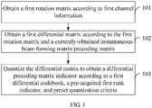
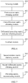
- An embodiment of the present invention provides a method for obtaining a precoding matrix indicator. As shown in FIG. 1 , the method includes:
- the obtaining the first rotation matrix according to the first channel information may specifically include:
- the obtaining the first rotation matrix according to the first channel information may specifically include:
- the obtaining the first rotation matrix according to the first channel information may specifically include:
- the first differential codebook is a differential dual-polarization codebook.
- the differential dual-polarization codebook is obtained according to a single-polarization differential codebook that includes 2 L codewords.
- the differential dual-polarization codeword includes 2 L+1 codewords.
- 2 L codewords are the same as those in the differential single-polarization codebook.
- Other 2 L codewords are obtained by left-multiplying each codeword in the differential single-polarization codebook by a preset diagonal matrix, where N is an even number greater than or equal to 2, and L represents the number of information bits occupied by feedback of a codeword in the differential single-polarization codebook.
- the method further includes:
- the method further includes:
- the reconstructing, by the data sender, the beam forming matrix/precoding matrix according to the differential precoding matrix indicator and the obtained second rotation matrix and by using the second differential codebook and the pre-acquired second rank indicator may specifically include:
- the obtaining the second rotation matrix according to the second channel information may specifically include:
- the obtaining the second rotation matrix according to the second channel information may specifically include:
- the obtaining the second rotation matrix according to the second channel information may specifically include:
- the method further includes:
- the first non-differential codebook is a dual-polarization non-differential codebook.
- the dual-polarization non-differential codebook is obtained according to a single-polarization non-differential codebook that includes 2 L codewords.
- the non-differential dual-polarization codeword includes 2 L+1 codewords.
- 2 L codewords are the same as those in the non-differential single-polarization codebook.
- L codewords are obtained by left-multiplying each codeword in the non-differential single-polarization codebook by a preset diagonal matrix, where N is an even number greater than or equal to 2, and L represents the number of information bits occupied by feedback of a codeword in the non-differential single-polarization codebook.
- the method further includes:
- the differential PMI is obtained according to the channel information, the differential PMI is used for feedback, and the information that already exists in the channel may be used, which not only reduces an overhead, but also makes full use of a correlation of a channel between a frequency domain and a time domain, thus improving the feedback accuracy, and fulfilling requirements of technologies such as MU-MIMO (Multiple User MIMO, multiple user MIMO) or CoMP (Coordinated Multiple Point transmission, coordinated multiple point transmission).
- MU-MIMO Multiple User MIMO, multiple user MIMO
- CoMP Coordinatd Multiple Point transmission, coordinated multiple point transmission
- An embodiment of the present invention provides a method for obtaining a precoding matrix indicator.
- the method performs feedback by using a differential PMI based on a long-term channel covariance matrix.
- the following takes the downlink (namely, an eNode B sends data to a UE, and the UE feeds back a precoding matrix indicator to the eNode B) as an example for description.
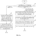
- the method includes:
- the eNode B may instruct the UE through high-layer signaling or a downlink physical control channel.
- different identifiers may be used to differentiate whether to use the non-differential PMI or the differential PMI based on the first long-term channel covariance matrix R UE .
- 0 may be used to indicate it is instructed to use the non-differential PMI
- 1 may be used to indicate it is instructed to use the differential PMI based on the first long-term channel covariance matrix R UE .
- the setting is not limited to this manner, and may be determined flexibly according to an actual application condition.
- the first long-term channel covariance matrix R UE is obtained by the UE through averaging multiple channel matrixes obtained by the UE on a single or multiple subcarriers in a preset time period.
- the preset time period may be set according to the actual application condition, for example, may be set to 1 second, or 2 seconds.
- H i represents a channel matrix that is obtained in the preset time period and exists on a subcarrier i in different timeslots or sub-bands
- ⁇ i is a weighting coefficient of H i and is used for smooth averaging and normalizing.
- the first long-term channel covariance matrix R UE is not necessarily obtained through the formula (1).
- the UE performs an eigenvalue decomposition on the first long-term channel covariance matrix R UE to obtain an eigen matrix U UE of the first long-term channel covariance matrix R UE , and uses the eigen matrix U UE as a first rotation matrix.
- the performing eigenvalue decomposition on the first long-term channel covariance matrix R UE is as shown in the formula (2):
- R UE U UE ⁇ UE
- U UE H ⁇ UE represents a diagonal matrix constructed by using the eigenvalue of R UE as a diagonal element;
- U UE represents a matrix constructed by using all eigenvectors of the first long-term channel covariance matrix R UE as columns.
- U UE is called the eigen matrix of the first long-term channel covariance matrix R UE .
- the UE obtains a first differential matrix D according to the first rotation matrix U UE and a currently-obtained instantaneous BF matrix/precoding matrix V .
- the first differential matrix D U UE H V
- V represents the currently-obtained instantaneous BF matrix/precoding matrix.
- V is an ideal BF matrix/precoding matrix that may reflect the channel status of the UE, and may be obtained according to the channel status of the UE.
- V may be obtained by decomposing a singular value of an instantaneous channel matrix of the UE, or may be obtained through other various methods in the prior art, and details are not further described here.
- the UE quantizes the first differential matrix D to obtain a differential precoding matrix D ⁇ according to a first differential codebook, a pre-acquired first RI, and preset quantization criteria.
- the first RI may be pre-acquired in various modes in the prior art, and details are not further described here.
- D ⁇ represents a differential precoding matrix
- a differential PMI corresponding to D ⁇ is expressed as PMI dif
- ⁇ F represents a Frobenius norm
- C d represents the first differential codebook known by both the eNodeB and the UE
- D i represents a codeword in the first differential codebook C d .
- the first differential codebook here may be any differential codebook in the prior art according to the actual application condition.
- the quantization criteria of the first differential matrix D are not limited to the criteria shown in the formula (4), and may be other criteria selected according to the actual application condition, for example, maximum capacity criteria or various criteria based on a minimum distance.
- the UE feeds back the differential PMI dif to the eNode B.
- the eNode B performs eigenvalue decomposition on a second long-term channel covariance matrix R NB to obtain an eigen matrix U NB of the second long-term channel covariance matrix R NB , and uses the eigen matrix U NB as a second rotation matrix; the eNode B receives the differential PMI dif , and obtains a second differential matrix D according to the differential PMI dif and by using a second differential codebook and a pre-acquired second RI.
- the second differential codebook and the second RI that are applied in this step are consistent with the first differential codebook and the first RI that are applied in step 204.
- the second long-term channel covariance matrix R NB is obtained by the eNode B through averaging multiple channel matrixes obtained by the eNode B on a single or multiple subcarriers in the preset time period.
- the method that is the same as the method for obtaining the first long-term channel covariance matrix R UE is applied to ensure that the R UE obtained by the UE is basically consistent with the R NB obtained by the eNode B. For example, if the UE uses the formula (1) to obtain R UE in step 201, the eNode B in this step uses the formula (1) to obtain R NB , or makes the two consistent through other signaling interaction.
- R NB U NB ⁇ NB
- U NB H ⁇ NB represents a diagonal matrix constructed by using the eigenvalue of R NB as a diagonal element
- U NB represents a matrix constructed by using all eigenvectors of the second long-term channel covariance matrix R NB as columns.
- U NB is called the eigen matrix of the second long-term channel covariance matrix R NB .
- step 210 the eNode B reconstructs the BF matrix/precoding matrix V ⁇ obtained in step 203, and then step 210 is executed.
- V ⁇ U NB D ⁇
- the UE uses the first non-differential codebook and a pre-acquired third RI to obtain a non-differential PMI, and feeds back the non-differential PMI to the eNode B.
- the UE uses the first non-differential codebook and the pre-acquired third RI to quantize the currently-obtained instantaneous BF matrix/precoding matrix to obtain a non-differential PMI according to the maximum-capacity criteria and various criteria based on the minimum distance.
- the non-differential PMI is obtained according to a method in a 3GPP LTE R8 system.
- a non-differential codebook used in the 3GPP LTE R8 system is as shown in Table 1.
- a non-differential PMI may be selected in Table 1 for feedback according to the actual application condition.
- the non-differential PMI is obtained through other methods in the prior art. 209.
- the eNode B receives the non-differential PMI, and obtains the BF matrix/precoding matrix V ⁇ obtained in step 208 according to the non-differential PMI and by using the second non-differential codebook and a pre-acquired fourth RI.
- the second non-differential codebook and the fourth RI are consistent with the first non-differential codebook and the third RI respectively.
- the BF matrix/precoding matrix V ⁇ is obtained according to the corresponding method in step 208, which is not repeatedly described here.
- the eNode B uses the obtained BF matrix/precoding matrix V ⁇ to preprocess data s to be sent, and sends the preprocessed data s to be sent to the UE through a transmitting antenna.
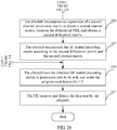
- the UE receives a reception signal y , and performs data detection on the reception signal y .
- a PMI may be fed back for an entire system bandwidth, or the system may be divided into multiple BPs (Bandwidth Part, bandwidth part), and each BP includes multiple sub-bands. A PMI is fed back for each sub-band.
- the eNode B in step 201 needs to decide whether to use the non-differential PMI or use the differential PMI based on the long-term channel covariance matrix for feedback. Further, the eNode B notifies the UE through high-layer signaling or a physical downlink control channel, and the UE receives the notification. Other processes are similar to the foregoing steps, and are not repeatedly described here.
- a differential PMI is obtained according to the long-term channel covariance matrix, and the differential PMI is used for feedback. Therefore, the information that already exists in the channel may be used, which not only reduces an overhead, but also makes use of a correlation of a channel between a frequency domain and a time domain, thus improving the feedback accuracy, and fulfilling requirements of technologies such as MU-MIMO or CoMP. Further, whether to use non-differential feedback or differential feedback may be chosen, which may improve flexibility of the feedback.
- An embodiment of the present invention provides a method for obtaining a precoding matrix indicator.
- the method performs feedback by using a differential PMI based on a reference PMI (expressed by PMI ref ).
- the following takes the uplink (namely, a UE sends data to an eNode B, and the eNode B feeds back a PMI to the UE) as an example for description.
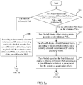
- the method includes:
- the obtaining the first rotation matrix Q NB according to the reference PMI ref may be:
- Each column in a low-rank codeword (each column being normalized) in the codebook is a subset of each column in a high-rank codeword (each column being normalized) in the codebook.
- the reference PMI ref is 6, and the pre-acquired first rank indicator is 2, and therefore, an applied codebook is as shown in Table 1.
- the obtaining the first rotation matrix Q NB according to the reference PMI ref may also be:
- the first rotation matrix Q NB V ⁇ ref Q 2 P
- P is a unitary matrix negotiated between the eNode B and the UE.
- the method of the QR decomposition in the formula (10) may be based on the Householder (Householder) transformation, or the Givens (Givens) rotation, or the Gram-Schimdt (Gram-Schimdt) quadrature, or variations or combinations of such methods, provided that the eNodeB and the UE need to use the same QR decomposition method through negotiation.
- the obtaining the first rotation matrix Q NB according to the reference PMI ref be:
- Q NB 1 , Q NB 2 ... Q NBn may be obtained in the same method as that for obtaining the first rotation matrix Q NB .
- Q NBn represents a rotation matrix at current time (or sub-band) that is obtained according to the reference PMI ref at the current time (or sub-band); and
- Q NB 2 ... Q NBn -1 represent rotation matrixes obtained according to the differential PMI at each time (or sub-band) before the current time (or sub-band) and by using the QR decomposition or the nesting characteristics of the codebook.
- the eNode B obtains a first differential matrix D according to the first rotation matrix Q NB and a currently-obtained instantaneous BF matrix/precoding matrix V. This step is similar to step 203, and is not repeatedly described here.
- the eNode B quantizes the first differential matrix D to obtain a differential PMI D ⁇ according to a second differential codebook, a pre-acquired second RI, and preset quantization criteria. This step is similar to step 204, and is not repeatedly described here. 305.
- the eNode B notifies the UE of the differential PMI D ⁇ .
- the UE obtains a second rotation matrix Q UE according to the reference PMI ref ; the UE receives the differential PMI D ⁇ , and obtains a second differential matrix D according to the differential PMI D ⁇ and by using the second differential codebook and the pre-acquired second RI.
- the eNode B and the UE negotiate in advance to use the same reference PMI ref . Moreover, the same method for obtaining the first rotation matrix Q NB in step 302 is applied, and the second rotation matrix Q UE is obtained according to the reference PMI ref .
- step 310 is executed. This step is similar to step 207, and is not repeatedly described here.
- the eNode B uses the first non-differential codebook and a pre-acquired third RI to obtain a non-differential PMI, and notifies the UE of the non-differential PMI.
- This step is similar to step 208, and is not repeatedly described here.
- the UE receives the second non-differential PMI, and, according to the second non-differential PMI, uses the second non-differential codebook and a pre-acquired fourth RI to obtain the BF matrix/precoding matrix V ⁇ .
- This step is similar to step 209, and is not repeatedly described here.
- the UE uses the obtained BF matrix/precoding matrix V ⁇ to preprocess data s to be sent, and sends the preprocessed data s to be sent to the eNode B through a transmitting antenna. This step is similar to step 210, and is not repeatedly described here.
- the eNodeB receives a reception signal y , and uses y to perform data detection. This step is similar to step 211, and is not repeatedly described here.
- a PMI may be fed back for an entire system bandwidth, or the system may be divided into multiple BPs, and each BP includes multiple sub-bands. A PMI is fed back for each sub-band.
- the eNodeB in step 301 needs to instruct the UE whether to use the non-differential PMI or use the differential PMI based on the reference PMI for feedback.
- Other processes are similar to the foregoing steps, and are not repeatedly described here.
- a differential PMI is obtained according to the reference PMI, and the differential PMI is used for feedback. Therefore, the information that already exists in the channel may be used, which makes use of a correlation of a channel between a frequency domain and a time domain, thus improving the feedback accuracy, and fulfilling requirements of technologies such as MU-MIMO or CoMP. Further, whether to use non-differential feedback or differential feedback may be chosen, which may improve flexibility of the feedback.
- An embodiment of the present invention provides a method for obtaining a precoding matrix indicator. This embodiment differs from the embodiment 2 and the embodiment 3 in that:
- a current differential PMI may be obtained based on a long-term channel covariance matrix and a previous differential PMI, as detailed below:
- U UE may be obtained in the same method as that for obtaining the first rotation matrix U UE in the embodiment 2.
- U UE may be called a first reference rotation matrix.
- Q UE 1 ⁇ Q UE 2 ⁇ Q UEn may be obtained in the same method as that for obtaining the first rotation matrix Q NB in the embodiment 3.
- Q UE 1 represents a rotation matrix at current time (or sub-band) that is obtained according to a reference PMI ref at the current time (or sub-band); and
- Q UE 2 ⁇ Q UEn represent rotation matrixes obtained according to a differential PMI after Q UE 1 .
- U NB may be obtained in the same method as that for obtaining the second rotation matrix U NB in the embodiment 2
- Q NB 1 , Q NB 2 ⁇ Q NBn may be obtained in the same method as that for obtaining the first rotation matrix Q NB in the embodiment 3.
- the detailed meanings are similar to those in the formula (12), and are not repeatedly described here.
- the eNode B needs to instruct the UE to use the non-differential PMI or use the differential PMI based on the long-term channel covariance matrix and the reference PMI ref , and other processes are similar to those in the embodiment 2, and are not repeatedly described here.
- the eNode B needs to determine whether the eNode B uses the non-differential PMI or uses the differential PMI based on the long-term channel covariance matrix and the reference PMI ref for feedback, and notifies the UE; and other processes are similar to those in the embodiment 3, and are not repeatedly described here.
- a differential PMI is obtained based on the long-term channel covariance matrix and the reference PMI, and the differential PMI is used for feedback. Therefore, the information that already exists in the channel may be used, which not only reduces an overhead, but also makes use of a correlation of a channel between a frequency domain and a time domain, thus improving the feedback accuracy, and fulfilling requirements of technologies such as MU-MIMO or CoMP. Further, whether to use non-differential feedback or differential feedback may be chosen, which may improve flexibility of the feedback.
- an embodiment of the present invention provides a method for obtaining a precoding matrix indicator, and this method differs from the methods in the embodiments 2, 3, and 4 in that:
- a codebook in this embodiment is not the codebook in the prior art, but is a codebook (also known as dual-polarization codebook) that corresponds to the configuration of the dual-polarization transmitting antenna and is obtained according to a codebook (also known as single-polarization codebook) corresponding to the configuration of a single-polarization transmitting antenna in the prior art.
- a codebook corresponding to the configuration of N (N is an even number) single-polarization transmitting antennas include 2 L codewords (precoding matrix), where L represents the number of information bits occupied by feedback of one of the codewords (if the feedback of a single codeword in the single-polarization codebook needs L bits of information, the feedback of a single codeword in the dual-polarization codebook needs L+1 bits of information).
- diag ⁇ 1, ⁇ ,1,-1, ⁇ ,-1 ⁇ represents a diagonal matrix in which the first N/2 diagonal elements are Is, and the last N/2 diagonal elements are -Is.
- a 1 st antenna, a 3 rd antenna, a 5 th antenna, ..., and a N-1 th antenna are a group of co-polarization antennas
- a 2 nd antenna, a 4 th antenna, a 6 th antenna, ..., and an N th antenna are another group of co-polarization antennas.
- the diagonal elements of the diagonal matrix are 1, -1, 1, -1, 1, -1, ..., 1, and -1.
- a differential PMI is obtained according to the channel information, and the differential PMI is used for feedback. Therefore, the information that already exists in the channel may be used, which not only reduces an overhead, but also makes use of a correlation of a channel between a frequency domain and a time domain, thus improving the feedback accuracy, and fulfilling requirements of technologies such as MU-MIMO or CoMP. Further, whether to use the non-differential PMI or the differential PMI for feedback may be chosen, which may improve flexibility of the feedback.
- the codebook of the dual-polarization transmitting antenna is constructed based on the codebook of the single-polarization transmitting antenna, which may make full use of the features of the configuration of the dual-polarization transmitting antenna, and improve performance of the codebook under the configuration of the dual-polarization transmitting antenna.
- a codebook may be selected according to PH (Power Headroom, power headroom) of a UE, which specifically includes the following two modes:
- a differential PMI is obtained according to the channel information, and the differential PMI is used for feedback. Therefore, the information that already exists in the channel may be used, which not only reduces an overhead, but also makes use of a correlation of a channel between a frequency domain and a time domain, thus improving the feedback accuracy, and fulfilling requirements of technologies such as MU-MIMO or CoMP. Further, whether to use the non-differential PMI or the differential PMI for feedback may be chosen, which may improve flexibility of the feedback.
- adaptive switching between the CMP codebook and the CMF codebook may be performed according to the power headroom, and advantages of the CMP codebook and the CMF codebook may be made use of according to the current power usage of the UE or the eNode B.
- An embodiment of the present invention provides an apparatus for obtaining a precoding matrix indicator. As shown in FIG. 4 , the apparatus includes:
- the first rotation matrix obtaining module 401 may specifically include:
- the first rotation matrix obtaining module 401 may specifically include:
- the first rotation matrix obtaining module 401 may specifically include:
- the apparatus may further include:
- the apparatus may further include:
- the differential PMI is obtained according to the channel information, the differential PMI is used for feedback, and the information that already exists in the channel may be used, which not only reduces an overhead, but also makes full use of a correlation of a channel between a frequency domain and a time domain, thus improving the feedback accuracy, and fulfilling requirements of technologies such as MU-MIMO or CoMP.
- An embodiment of the present invention provides a data sending apparatus. As shown in FIG. 7 , the apparatus includes:
- the obtaining the second rotation matrix according to the second channel information may specifically include:
- the obtaining the second rotation matrix according to the second channel information may specifically include:
- the beam forming matrix/precoding matrix is reconstructed. Therefore, the information that already exists in the channel may be used, which not only reduces an overhead, but also makes full use of a correlation of a channel between a frequency domain and a time domain, thus improving the accuracy of the reconstructed beam forming matrix/precoding matrix, and fulfilling requirements of technologies such as MU-MIMO or CoMP.
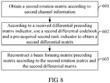
- An embodiment of the present invention provides a method for reconstructing a beam forming matrix/precoding matrix. As shown in FIG. 8 , the method includes:
- the obtaining the second rotation matrix according to the second channel information may specifically include:
- the obtaining the second rotation matrix according to the second channel information may specifically include:
- the obtaining the second rotation matrix according to the second channel information may specifically include:
- the differential precoding matrix indicator is obtained by a data receiving apparatus according to a first rotation matrix and an instantaneous beam forming matrix/precoding matrix, which are obtained by the data receiving apparatus, and by using the first differential codebook and the pre-acquired first rank indicator, where the first rotation matrix is obtained according to a first channel message, the second channel information is consistent with the first channel information, and the second differential codebook and the second rank indicator are consistent with the first differential codebook and the first rank indicator respectively.
- the beam forming matrix/precoding matrix is reconstructed. Therefore, the information that already exists in the channel may be used, which not only reduces an overhead, but also makes full use of a correlation of a channel between a frequency domain and a time domain, thus improving the accuracy of the reconstructed beam forming matrix/precoding matrix, and fulfilling requirements of technologies such as MU-MIMO or CoMP.
Landscapes
- Engineering & Computer Science (AREA)
- Computer Networks & Wireless Communication (AREA)
- Signal Processing (AREA)
- Physics & Mathematics (AREA)
- Mathematical Physics (AREA)
- Radio Transmission System (AREA)
- Compression, Expansion, Code Conversion, And Decoders (AREA)
Claims (10)
- Procédé d'obtention d'un indicateur de matrice de précodage, le procédé étant caractérisé en ce qu'il comprend :l'obtention (101) d'une première matrice de rotation compte tenu de premières informations de canal ;l'obtention (102, 203) d'une première matrice différentielle compte tenu de la première matrice de rotation et d'une matrice de formation de faisceaux ou matrice de précodage instantanée obtenue sur le moment et reflétant l'état de canal du moment ;etla quantification (103), compte tenu d'un premier dictionnaire différentiel, d'un premier indicateur de rang préalablement acquis et de critères de quantification préétablis, de la première matrice différentielle dans le but d'obtenir un indicateur de matrice de précodage différentiel ;dans lequel les premières informations de canal constituent une première matrice de covariance de canal à long terme, l'obtention de la première matrice de rotation compte tenu des premières informations de canal comprend : la réalisation d'une décomposition en valeurs propres sur la première matrice de covariance de canal à long terme dans le but d'obtenir une matrice propre de la première matrice de covariance de canal à long terme, la première matrice de covariance de canal à long terme étant obtenue par calcul de la moyenne de matrices de canal multiples obtenues au niveau d'un équipement d'utilisateur ou d'un noeud B évolué, eNB, sur une sous-porteuse simple ou des sous-porteuses multiples dans une période de temps préétablie ; et l'utilisation de la matrice propre de la première matrice de covariance de canal à long terme comme la première matrice de rotation ; oudans lequel les premières informations de canal constituent un indicateur de matrice de précodage de référence, l'obtention de la première matrice de rotation compte tenu des premières informations de canal comprend : si l'indicateur de matrice de précodage de référence est orthogonal à des colonnes d'une matrice de précodage correspondant au premier indicateur de rang préalablement acquis et le rang est plein, la normalisation de colonnes respectives de la matrice de précodage et l'utilisation d'une matrice de précodage normalisée comme la première matrice de rotation ; si l'indicateur de matrice de précodage de référence est orthogonal à des colonnes d'une matrice de précodage correspondant au premier indicateur de rang préalablement acquis et le rang n'est pas plein, mais un dictionnaire correspondant à l'indicateur de matrice de précodage de référence satisfait à des caractéristiques d'imbrication, la sélection d'une matrice de précodage de plein rang correspondant à l'indicateur de matrice de précodage de référence, la normalisation de colonnes respectives de la matrice de précodage de plein rang, et l'utilisation d'une matrice de précodage de plein rang normalisée comme la première matrice de rotation ; ou, si les premières informations de canal constituent l'indicateur de matrice de précodage de référence, l'obtention de la première matrice de rotation compte tenu des premières informations de canal comprend : la normalisation de colonnes respectives de matrices de précodage correspondant à l'indicateur de matrice de précodage de référence et au premier indicateur de rang préalablement acquis ; et la réalisation d'une décomposition QR pour une matrice de précodage normalisée dans le but d'obtenir la première matrice de rotation.
- Procédé selon la revendication 1, le procédé comprenant en outre, suite à l'obtention de l'indicateur de matrice de précodage différentielle :le retour d'information (205, 305) sur l'indicateur de matrice de précodage différentiel vers un émetteur de données, de sorte que l'émetteur de données reconstitue une matrice de formation de faisceaux ou matrice de précodage compte tenu de l'indicateur de matrice de précodage différentiel et d'une deuxième matrice de rotation obtenue et en utilisant un deuxième dictionnaire différentiel et un deuxième indicateur de rang préalablement acquis, la deuxième matrice de rotation étant obtenue par l'émetteur de données compte tenu des deuxièmes informations de canal, et les deuxièmes informations de canal, la deuxième matrice de rotation, le deuxième dictionnaire différentiel et le deuxième indicateur de rang étant respectivement identiques aux premières informations de canal, à la première matrice de rotation, au premier dictionnaire différentiel et au premier indicateur de rang.
- Procédé selon la revendication 1, le procédé comprenant en outre : préalablement à l'obtention de la première matrice de rotation compte tenu des premières informations de canal :l'obtention (201, 301) d'un message d'utilisation d'un indicateur de matrice de précodage différentiel ou d'un indicateur de matrice de précodage non différentiel pour le retour d'information ;la réalisation (201, 301) de l'étape d'obtention de la première matrice de rotation compte tenu des premières informations de canal lors de l'obtention du message d'utilisation de l'indicateur de matrice de précodage différentiel pour le retour d'information ; etl'utilisation (201, 301) d'un premier dictionnaire non différentiel et d'un troisième indicateur de rang préalablement acquis dans le but d'obtenir un indicateur de matrice de précodage non différentiel compte tenu de la matrice de formation de faisceaux ou matrice de précodage instantanée lors de l'obtention du message d'utilisation de l'indicateur de matrice de précodage non différentiel pour le retour d'information.
- Procédé selon la revendication 3, dans lequel :l'indicateur de matrice de précodage non différentiel fait l'objet du retour d'information pour toute une largeur de bande système ou pour chaque sous-bande ; etl'indicateur de matrice de précodage différentiel fait l'objet du retour d'information pour toute la largeur de bande système ou pour chaque sous-bande.
- Procédé selon la revendication 3, dans lequel :si un système local présente la configuration de N antennes émettrices à double polarisation, le premier dictionnaire non différentiel est un dictionnaire non différentiel à double polarisation ; le dictionnaire non différentiel à double polarisation est obtenu compte tenu d'un dictionnaire non différentiel à polarisation simple comprenant 2L mots de code ; le dictionnaire non différentiel à double polarisation comprend 2L+1 mots de code ; dans le dictionnaire non différentiel à double polarisation, 2L mots de code sont identiques à ceux dans le dictionnaire non différentiel à polarisation simple ;d'autres 2L mots de code sont obtenus par multiplication à gauche de chaque mot de code dans le dictionnaire non différentiel à polarisation simple par une matrice diagonale préétablie, N étant un nombre pair supérieur ou égal à 2, et L représentant le nombre de bits d'information occupés par le retour d'information sur un mot de code dans le dictionnaire non différentiel à polarisation simple.
- Procédé selon la revendication 3, le procédé comprenant en outre, si un dictionnaire non différentiel limité en puissance et un dictionnaire non différentiel non limité en puissance coexistent au niveau de l'équipement d'utilisateur ou du noeud B évolué :la sélection, parmi le dictionnaire non différentiel limité en puissance et le dictionnaire non différentiel non limité en puissance, d'un dictionnaire particulier comme le premier dictionnaire non différentiel compte tenu d'une réserve de puissance au niveau de l'équipement d'utilisateur ou du noeud B évolué et d'une valeur de seuil de réserve de puissance préétablie.
- Appareil permettant d'obtenir un indicateur de matrice de précodage, l'appareil étant caractérisé en ce qu'il comprend :un module d'obtention de première matrice de rotation (401), configuré pour obtenir une première matrice de rotation compte tenu de premières informations de canal ;un module d'obtention de première matrice différentielle (402), configuré pour obtenir une première matrice différentielle compte tenu de la première matrice de rotation et d'une matrice de formation de faisceaux ou matrice de précodage instantanée obtenue sur le moment et reflétant l'état de canal du moment, après que le module d'obtention de première matrice de rotation (401) a obtenu la première matrice de rotation ; etun module d'obtention d'indicateur de matrice de précodage différentiel (403), configuré pour quantifier, compte tenu d'un premier dictionnaire différentiel, d'un premier indicateur de rang préalablement acquis et de critères de quantification préétablis, la première matrice différentielle dans le but d'obtenir un indicateur de matrice de précodage différentiel, après que le module d'obtention de première matrice différentielle a obtenu la matrice différentielle ;dans lequel les premières informations de canal constituent une première matrice de covariance de canal à long terme, le module d'obtention de première matrice de rotation comprend : une unité d'obtention de matrice propre, configurée pour réaliser une décomposition en valeurs propres sur la première matrice de covariance de canal à long terme dans le but d'obtenir une matrice propre de la première matrice de covariance de canal à long terme, la première matrice de covariance de canal à long terme étant obtenue par calcul de la moyenne de matrices de canal multiples obtenues localement sur une sous-porteuse simple ou des sous-porteuses multiples dans une période de temps préétablie ; et une première unité d'obtention de matrice de rotation, configurée pour utiliser la matrice propre de la première matrice de covariance de canal à long terme comme la première matrice de rotation, après que l'unité d'obtention de matrice propre a obtenu la matrice propre ; oudans lequel les premières informations de canal constituent un indicateur de matrice de précodage de référence, le module d'obtention de première matrice de rotation comprend : une deuxième unité d'obtention de matrice de rotation, configurée pour normaliser des colonnes respectives d'une matrice de précodage et utiliser une matrice de précodage normalisée comme la première matrice de rotation, si l'indicateur de matrice de précodage de référence est orthogonal à des colonnes de la matrice de précodage correspondant au premier indicateur de rang préalablement acquis et le rang est plein ; et une troisième unité d'obtention de matrice de rotation,configurée pour : sélectionner une matrice de précodage de plein rang correspondant à l'indicateur de matrice de précodage de référence, normaliser des colonnes respectives de la matrice de précodage de plein rang et utiliser une matrice de précodage de plein rang normalisée comme la première matrice de rotation, si l'indicateur de matrice de précodage de référence est orthogonal à des colonnes d'une matrice de précodage correspondant au premier indicateur de rang préalablement acquis et le rang n'est pas plein, mais un dictionnaire correspondant à l'indicateur de matrice de précodage de référence satisfait à des caractéristiques d'imbrication ; ou, si les premières informations de canal constituent l'indicateur de matrice de précodage de référence, le module d'obtention de première matrice de rotation comprend : une quatrième unité d'obtention de matrice de rotation, configurée pour normaliser des colonnes respectives de matrices de précodage correspondant à l'indicateur de matrice de précodage de référence et au premier indicateur de rang préalablement acquis ; et réaliser une décomposition QR pour une matrice de précodage normalisée dans le but d'obtenir la première matrice de rotation.
- Appareil selon la revendication 7, comprenant en outre :un module de sélection (404), configuré pour : sélectionner, parmi un dictionnaire différentiel limité en puissance et un dictionnaire différentiel non limité en puissance, un dictionnaire particulier comme un premier dictionnaire différentiel compte tenu d'une réserve de puissance au niveau de l'appareil et d'une valeur de seuil de réserve de puissance préétablie si le dictionnaire différentiel limité en puissance et le dictionnaire différentiel non limité en puissance coexistent au niveau de l'appareil.
- Appareil selon l'une quelconque des revendications 7 et 8, comprenant en outre :un module de retour d'information (405), configuré pour : assurer un retour d'information sur l'indicateur de matrice de précodage différentiel vers un émetteur de données après que le module d'obtention d'indicateur de matrice de précodage différentiel a obtenu l'indicateur de matrice de précodage différentiel, de sorte que l'émetteur de données reconstitue une matrice de formation de faisceaux ou matrice de précodage compte tenu de l'indicateur de matrice de précodage différentiel et d'une deuxième matrice de rotation obtenue et en utilisant un deuxième dictionnaire différentiel et un deuxième indicateur de rang préalablement acquis, la deuxième matrice de rotation étant obtenue par l'émetteur de données compte tenu des deuxièmes informations de canal, et les deuxièmes informations de canal, la deuxième matrice de rotation, le deuxième dictionnaire différentiel et le deuxième indicateur de rang étant respectivement identiques aux premières informations de canal, à la première matrice de rotation, au premier dictionnaire différentiel et au premier indicateur de rang.
- Système, caractérisé en ce qu'il comprend un appareil permettant d'obtenir un indicateur de matrice de précodage selon l'une quelconque des revendications 7 à 9, et comprenant en outre un appareil émetteur de données, l'appareil émetteur de données comprenant :un module d'obtention de deuxième matrice de rotation (501), configuré pour obtenir une deuxième matrice de rotation compte tenu de deuxièmes informations de canal ;un module d'obtention de deuxième matrice différentielle (502), configuré pour : obtenir une deuxième matrice différentielle compte tenu d'un indicateur de matrice de précodage différentiel reçu et en utilisant un deuxième dictionnaire différentiel et un deuxième indicateur de rang préalablement acquis, l'indicateur de matrice de précodage différentiel étant obtenu par l'appareil permettant d'obtenir un indicateur de matrice de précodage compte tenu d'une première matrice de rotation et d'une matrice de formation de faisceaux ou matrice de précodage instantanée, obtenues par l'appareil récepteur de données, et en utilisant un premier dictionnaire différentiel et un premier indicateur de rang préalablement acquis, la première matrice de rotation étant obtenue compte tenu d'un premier message de canal, les deuxièmes informations de canal étant conformes aux premières informations de canal, et le deuxième dictionnaire différentiel et le deuxième indicateur de rang étant conformes respectivement au premier dictionnaire différentiel et au premier indicateur de rang ; etun module de reconstitution de matrice de précodage (503), configuré pour reconstituer la matrice de formation de faisceaux ou matrice de précodage compte tenu de la deuxième matrice de rotation obtenue par le module d'obtention de deuxième matrice de rotation (501) et de la matrice différentielle obtenue par le module d'obtention de deuxième matrice différentielle (502).
Applications Claiming Priority (2)
| Application Number | Priority Date | Filing Date | Title |
|---|---|---|---|
| CN2009102352860A CN102035626B (zh) | 2009-09-30 | 2009-09-30 | 一种获取预编码矩阵指示的方法和装置 |
| PCT/CN2010/077545 WO2011038697A1 (fr) | 2009-09-30 | 2010-09-30 | Procédé et dispositif permettant d'acquérir un indicateur de matrice de précodage |
Publications (3)
| Publication Number | Publication Date |
|---|---|
| EP2485408A1 EP2485408A1 (fr) | 2012-08-08 |
| EP2485408A4 EP2485408A4 (fr) | 2012-08-08 |
| EP2485408B1 true EP2485408B1 (fr) | 2017-06-14 |
Family
ID=43825592
Family Applications (1)
| Application Number | Title | Priority Date | Filing Date |
|---|---|---|---|
| EP10819926.6A Active EP2485408B1 (fr) | 2009-09-30 | 2010-09-30 | Procédé et dispositif permettant d'acquérir un indicateur de matrice de précodage |
Country Status (5)
| Country | Link |
|---|---|
| US (1) | US8553799B2 (fr) |
| EP (1) | EP2485408B1 (fr) |
| JP (1) | JP5489029B2 (fr) |
| CN (1) | CN102035626B (fr) |
| WO (1) | WO2011038697A1 (fr) |
Cited By (2)
| Publication number | Priority date | Publication date | Assignee | Title |
|---|---|---|---|---|
| US12489504B2 (en) * | 2019-04-04 | 2025-12-02 | Nokia Technologies Oy | Uplink control information |
| US20250379622A1 (en) * | 2024-06-05 | 2025-12-11 | Nokia Solutions And Networks Oy | Wideband beamforming for mimo systems |
Families Citing this family (28)
| Publication number | Priority date | Publication date | Assignee | Title |
|---|---|---|---|---|
| KR101092686B1 (ko) * | 2010-01-08 | 2011-12-09 | 서울대학교산학협력단 | 직교 주파수 분할 다중 접속 기반 다중안테나 무선 시스템에서 송신 빔포밍 방법 및 장치 |
| CN102158971B (zh) | 2010-02-11 | 2014-11-05 | 华为技术有限公司 | 实现半持续调度业务或类似半持续调度业务的方法及设备 |
| US8446971B2 (en) * | 2010-08-23 | 2013-05-21 | Intel Corporation | Communication station and method for efficiently providing channel feedback for MIMO communications |
| CN102957496A (zh) * | 2011-08-19 | 2013-03-06 | 中兴通讯股份有限公司 | 一种实现码本重排的方法和系统 |
| CN102412942B (zh) * | 2011-10-18 | 2015-07-15 | 电信科学技术研究院 | Ri确定方法和设备 |
| US8737513B2 (en) * | 2011-11-11 | 2014-05-27 | Qualcomm Incorporated | Apparatus and method for jointly selecting precoding matrices in a MIMO multi-flow system |
| CN103326768B (zh) * | 2012-03-23 | 2016-06-22 | 华为技术有限公司 | 信道信息反馈的方法、装置及系统 |
| CN102801455B (zh) * | 2012-07-31 | 2015-12-16 | 华为技术有限公司 | 波束码本生成方法、波束搜索方法及相关装置 |
| CN103780366A (zh) * | 2012-10-17 | 2014-05-07 | 上海贝尔股份有限公司 | 协同多点传输的方法及装置 |
| JP6006428B2 (ja) * | 2012-10-23 | 2016-10-12 | エルジー エレクトロニクス インコーポレイティド | 無線通信システムにおいてチャネル状態情報をフィードバックする方法およびそのための装置 |
| EP3484075A1 (fr) * | 2013-03-08 | 2019-05-15 | Huawei Technologies Co. Ltd. | Procédé de rétroaction d'un indicateur matriciel de précodage, d'une extrémité de réception et d'une extrémité d'émission |
| EP3007380B1 (fr) * | 2013-06-29 | 2018-08-15 | Huawei Technologies Co., Ltd. | Procédé et dispositif de détermination d'indicateur de matrice de précodage, équipement d'utilisateur, et station de base |
| JP6165645B2 (ja) * | 2014-01-29 | 2017-07-19 | 日本電信電話株式会社 | 無線通信方法、無線通信システムおよび制御局装置 |
| US9800314B2 (en) * | 2014-03-05 | 2017-10-24 | Lg Electronics Inc. | Method and apparatus for measuring channel variation for massive antenna array based beamforming in wireless communication system |
| US10169816B2 (en) * | 2015-01-06 | 2019-01-01 | Morgan Stanley Services Group Inc. | Trading anomaly kill switch |
| CN105871441B (zh) * | 2015-01-21 | 2018-11-30 | 华邦电子股份有限公司 | 多输入多输出无线通信系统及其通道分解方法 |
| CN107210800A (zh) * | 2015-02-13 | 2017-09-26 | Lg电子株式会社 | 在多天线系统中基于公共反馈信息通信的方法和设备 |
| US10581462B2 (en) | 2015-12-01 | 2020-03-03 | Huawei Technologies Co., Ltd. | Signature-enabled polar encoder and decoder |
| KR102458077B1 (ko) * | 2016-03-22 | 2022-10-25 | 삼성전자 주식회사 | 이동 통신 시스템에서의 상향링크 제어 신호 전송 방법 및 장치 |
| WO2017164621A1 (fr) | 2016-03-22 | 2017-09-28 | 삼성전자 주식회사 | Procédé et appareil permettant de transmettre un signal de commande en liaison montante dans un système de communication mobile |
| WO2018026223A1 (fr) * | 2016-08-03 | 2018-02-08 | 엘지전자 주식회사 | Procédé destiné à un terminal pour le rapport de marge de puissance dans un système de communication sans fil, et terminal mettant en œuvre ce procédé |
| CN107612599A (zh) * | 2017-08-04 | 2018-01-19 | 深圳市金立通信设备有限公司 | 一种指示频率选择性预编码信息的方法、基站及用户设备 |
| CN110768701B (zh) * | 2018-07-27 | 2022-10-28 | 中兴通讯股份有限公司 | 信道状态处理方法及装置、系统、终端、基站、存储介质 |
| US10404339B1 (en) | 2018-08-09 | 2019-09-03 | At&T Intellectual Property I, L.P. | Precoding matrix indicator determination in wireless communication systems |
| CN111464260B (zh) * | 2019-01-21 | 2023-07-11 | 华为技术有限公司 | 一种信号发送、接收方法及设备 |
| CN115441911A (zh) * | 2021-06-01 | 2022-12-06 | 华为技术有限公司 | 通信处理方法和通信处理装置 |
| CN117441295A (zh) * | 2021-06-21 | 2024-01-23 | 联发科技(新加坡)私人有限公司 | 用于上行链路通信的高空间分辨率mimo预编码 |
| WO2025185827A1 (fr) * | 2024-03-08 | 2025-09-12 | Huawei Technologies Co., Ltd. | Procédé et appareil de transmission de données de liaison montante compressées |
Family Cites Families (18)
| Publication number | Priority date | Publication date | Assignee | Title |
|---|---|---|---|---|
| US20060039489A1 (en) * | 2004-08-17 | 2006-02-23 | Texas Instruments Incorporated | Method and apparatus for providing closed-loop transmit precoding |
| CN101036332A (zh) * | 2004-08-17 | 2007-09-12 | 德州仪器公司 | 用于提供闭环传输预编码的方法及设备 |
| US7885348B2 (en) | 2006-02-09 | 2011-02-08 | Intel Corporation | MIMO communication system and method for beamforming using polar-cap codebooks |
| KR101066151B1 (ko) * | 2006-08-17 | 2011-09-20 | 인터디지탈 테크날러지 코포레이션 | Mimo 무선 통신 시스템에서 효율적인 프리코딩 피드백을 제공하기 위한 방법 및 장치 |
| JP4709820B2 (ja) * | 2006-10-30 | 2011-06-29 | 株式会社エヌ・ティ・ティ・ドコモ | 受信装置、送信装置及びプリコーディング情報を提供する方法 |
| TWI508478B (zh) * | 2006-10-30 | 2015-11-11 | Interdigital Tech Corp | 無線發射/接收單元及用於處理在無線發射/接收單元中執行的回饋的方法 |
| JP4840088B2 (ja) * | 2006-11-08 | 2011-12-21 | ソニー株式会社 | 無線通信システム、並びに無線通信装置及び無線通信方法 |
| CN101146078A (zh) * | 2006-12-27 | 2008-03-19 | 中兴通讯股份有限公司 | 一种多输入多输出空间复用预编码矩阵的选择方法 |
| US8687715B2 (en) | 2007-02-12 | 2014-04-01 | Broadcom Corporation | Method and system for rate reduction pre-coding matrices |
| CN101262456A (zh) * | 2007-02-12 | 2008-09-10 | 美国博通公司 | 用于处理通信信号的方法和系统 |
| US7839945B2 (en) * | 2007-03-20 | 2010-11-23 | Nec Laboratories America, Inc. | Static and differential precoding codebook for MIMO systems |
| JP5361870B2 (ja) * | 2007-05-10 | 2013-12-04 | アルカテル−ルーセント | 複数入力通信システムにおいて送信されるデータを事前処理するための方法及び装置 |
| EP2034774B1 (fr) * | 2007-05-23 | 2009-10-07 | NTT DoCoMo Inc. | Appareil d'attribution de sous-canaux et procédé correspondant |
| CN101340219B (zh) * | 2007-07-04 | 2012-10-03 | 华为技术有限公司 | 信道状态信息反馈方法及无线收发装置 |
| US9225397B2 (en) * | 2007-07-10 | 2015-12-29 | Texas Instruments Incorporated | Efficient rank and precoding matrix feedback for MIMO systems |
| CN101400074A (zh) * | 2007-09-28 | 2009-04-01 | 夏普株式会社 | 减少预编码矩阵索引号反馈量的方法、用户设备及系统 |
| CN101471907A (zh) | 2007-12-28 | 2009-07-01 | 三星电子株式会社 | 多入多出系统中的预编码方法及使用该方法的装置 |
| CN101931440B (zh) | 2009-06-19 | 2014-04-02 | 华为技术有限公司 | 信道状态信息获取方法及装置 |
-
2009
- 2009-09-30 CN CN2009102352860A patent/CN102035626B/zh active Active
-
2010
- 2010-09-30 WO PCT/CN2010/077545 patent/WO2011038697A1/fr not_active Ceased
- 2010-09-30 EP EP10819926.6A patent/EP2485408B1/fr active Active
- 2010-09-30 JP JP2012531227A patent/JP5489029B2/ja active Active
-
2012
- 2012-03-29 US US13/434,540 patent/US8553799B2/en active Active
Non-Patent Citations (1)
| Title |
|---|
| None * |
Cited By (2)
| Publication number | Priority date | Publication date | Assignee | Title |
|---|---|---|---|---|
| US12489504B2 (en) * | 2019-04-04 | 2025-12-02 | Nokia Technologies Oy | Uplink control information |
| US20250379622A1 (en) * | 2024-06-05 | 2025-12-11 | Nokia Solutions And Networks Oy | Wideband beamforming for mimo systems |
Also Published As
| Publication number | Publication date |
|---|---|
| WO2011038697A1 (fr) | 2011-04-07 |
| US8553799B2 (en) | 2013-10-08 |
| EP2485408A1 (fr) | 2012-08-08 |
| JP2013506360A (ja) | 2013-02-21 |
| US20120189075A1 (en) | 2012-07-26 |
| EP2485408A4 (fr) | 2012-08-08 |
| CN102035626A (zh) | 2011-04-27 |
| JP5489029B2 (ja) | 2014-05-14 |
| CN102035626B (zh) | 2013-06-12 |
Similar Documents
| Publication | Publication Date | Title |
|---|---|---|
| EP2485408B1 (fr) | Procédé et dispositif permettant d'acquérir un indicateur de matrice de précodage | |
| EP3963732B1 (fr) | Procédé et appareil d'amélioration d'indication de sous-ensemble de base pour un reporting csi basé sur deux livres de codes | |
| EP2406979B1 (fr) | Système et procédé de retour d'informations sur les canaux dans un système de communications sans fil | |
| EP2985924B1 (fr) | Procédé et appareil pour l'acquisition d'un indicateur de matrice de précodage et matrice de précodage | |
| CN102725967B (zh) | 用于信息反馈以及预编码的方法和装置 | |
| US8842773B2 (en) | Method and apparatus for using factorized precoding | |
| US8644415B2 (en) | Method for precoding using a block diagonal matrix | |
| EP2478644B1 (fr) | Système et procédé de communication sans fil avec livres de code adaptatifs | |
| EP2594030B1 (fr) | Procédé et système de précodage | |
| EP2477342B1 (fr) | Procédé et système d'acquisition d'informations d'état de canal | |
| US8855577B2 (en) | System and method for assisted open loop multiple input, multiple output communications | |
| US20140105316A1 (en) | Method and system for spatial channel state information feedback for multiple-input multiple-output (mimo) | |
| US20110243207A1 (en) | System and Method for Adapting Codebooks | |
| EP2731277B1 (fr) | Procédé, dispositif et système d'émission multi-antenne | |
| KR102105338B1 (ko) | 다중 안테나 시스템의 송수신 장치 및 방법 |
Legal Events
| Date | Code | Title | Description |
|---|---|---|---|
| PUAI | Public reference made under article 153(3) epc to a published international application that has entered the european phase |
Free format text: ORIGINAL CODE: 0009012 |
|
| 17P | Request for examination filed |
Effective date: 20120330 |
|
| A4 | Supplementary search report drawn up and despatched |
Effective date: 20120628 |
|
| AK | Designated contracting states |
Kind code of ref document: A1 Designated state(s): AL AT BE BG CH CY CZ DE DK EE ES FI FR GB GR HR HU IE IS IT LI LT LU LV MC MK MT NL NO PL PT RO SE SI SK SM TR |
|
| DAX | Request for extension of the european patent (deleted) | ||
| 17Q | First examination report despatched |
Effective date: 20140612 |
|
| GRAP | Despatch of communication of intention to grant a patent |
Free format text: ORIGINAL CODE: EPIDOSNIGR1 |
|
| STAA | Information on the status of an ep patent application or granted ep patent |
Free format text: STATUS: GRANT OF PATENT IS INTENDED |
|
| INTG | Intention to grant announced |
Effective date: 20161121 |
|
| GRAS | Grant fee paid |
Free format text: ORIGINAL CODE: EPIDOSNIGR3 |
|
| GRAJ | Information related to disapproval of communication of intention to grant by the applicant or resumption of examination proceedings by the epo deleted |
Free format text: ORIGINAL CODE: EPIDOSDIGR1 |
|
| GRAL | Information related to payment of fee for publishing/printing deleted |
Free format text: ORIGINAL CODE: EPIDOSDIGR3 |
|
| STAA | Information on the status of an ep patent application or granted ep patent |
Free format text: STATUS: EXAMINATION IS IN PROGRESS |
|
| GRAP | Despatch of communication of intention to grant a patent |
Free format text: ORIGINAL CODE: EPIDOSNIGR1 |
|
| STAA | Information on the status of an ep patent application or granted ep patent |
Free format text: STATUS: GRANT OF PATENT IS INTENDED |
|
| INTC | Intention to grant announced (deleted) | ||
| INTG | Intention to grant announced |
Effective date: 20170418 |
|
| GRAA | (expected) grant |
Free format text: ORIGINAL CODE: 0009210 |
|
| STAA | Information on the status of an ep patent application or granted ep patent |
Free format text: STATUS: THE PATENT HAS BEEN GRANTED |
|
| AK | Designated contracting states |
Kind code of ref document: B1 Designated state(s): AL AT BE BG CH CY CZ DE DK EE ES FI FR GB GR HR HU IE IS IT LI LT LU LV MC MK MT NL NO PL PT RO SE SI SK SM TR |
|
| REG | Reference to a national code |
Ref country code: GB Ref legal event code: FG4D |
|
| REG | Reference to a national code |
Ref country code: CH Ref legal event code: EP Ref country code: AT Ref legal event code: REF Ref document number: 901859 Country of ref document: AT Kind code of ref document: T Effective date: 20170615 |
|
| REG | Reference to a national code |
Ref country code: IE Ref legal event code: FG4D |
|
| REG | Reference to a national code |
Ref country code: DE Ref legal event code: R096 Ref document number: 602010043020 Country of ref document: DE |
|
| REG | Reference to a national code |
Ref country code: NL Ref legal event code: MP Effective date: 20170614 |
|
| REG | Reference to a national code |
Ref country code: LT Ref legal event code: MG4D |
|
| PG25 | Lapsed in a contracting state [announced via postgrant information from national office to epo] |
Ref country code: GR Free format text: LAPSE BECAUSE OF FAILURE TO SUBMIT A TRANSLATION OF THE DESCRIPTION OR TO PAY THE FEE WITHIN THE PRESCRIBED TIME-LIMIT Effective date: 20170915 Ref country code: ES Free format text: LAPSE BECAUSE OF FAILURE TO SUBMIT A TRANSLATION OF THE DESCRIPTION OR TO PAY THE FEE WITHIN THE PRESCRIBED TIME-LIMIT Effective date: 20170614 Ref country code: NO Free format text: LAPSE BECAUSE OF FAILURE TO SUBMIT A TRANSLATION OF THE DESCRIPTION OR TO PAY THE FEE WITHIN THE PRESCRIBED TIME-LIMIT Effective date: 20170914 Ref country code: LT Free format text: LAPSE BECAUSE OF FAILURE TO SUBMIT A TRANSLATION OF THE DESCRIPTION OR TO PAY THE FEE WITHIN THE PRESCRIBED TIME-LIMIT Effective date: 20170614 Ref country code: FI Free format text: LAPSE BECAUSE OF FAILURE TO SUBMIT A TRANSLATION OF THE DESCRIPTION OR TO PAY THE FEE WITHIN THE PRESCRIBED TIME-LIMIT Effective date: 20170614 Ref country code: HR Free format text: LAPSE BECAUSE OF FAILURE TO SUBMIT A TRANSLATION OF THE DESCRIPTION OR TO PAY THE FEE WITHIN THE PRESCRIBED TIME-LIMIT Effective date: 20170614 |
|
| REG | Reference to a national code |
Ref country code: AT Ref legal event code: MK05 Ref document number: 901859 Country of ref document: AT Kind code of ref document: T Effective date: 20170614 |
|
| PG25 | Lapsed in a contracting state [announced via postgrant information from national office to epo] |
Ref country code: BG Free format text: LAPSE BECAUSE OF FAILURE TO SUBMIT A TRANSLATION OF THE DESCRIPTION OR TO PAY THE FEE WITHIN THE PRESCRIBED TIME-LIMIT Effective date: 20170914 Ref country code: NL Free format text: LAPSE BECAUSE OF FAILURE TO SUBMIT A TRANSLATION OF THE DESCRIPTION OR TO PAY THE FEE WITHIN THE PRESCRIBED TIME-LIMIT Effective date: 20170614 Ref country code: SE Free format text: LAPSE BECAUSE OF FAILURE TO SUBMIT A TRANSLATION OF THE DESCRIPTION OR TO PAY THE FEE WITHIN THE PRESCRIBED TIME-LIMIT Effective date: 20170614 Ref country code: LV Free format text: LAPSE BECAUSE OF FAILURE TO SUBMIT A TRANSLATION OF THE DESCRIPTION OR TO PAY THE FEE WITHIN THE PRESCRIBED TIME-LIMIT Effective date: 20170614 |
|
| PG25 | Lapsed in a contracting state [announced via postgrant information from national office to epo] |
Ref country code: CZ Free format text: LAPSE BECAUSE OF FAILURE TO SUBMIT A TRANSLATION OF THE DESCRIPTION OR TO PAY THE FEE WITHIN THE PRESCRIBED TIME-LIMIT Effective date: 20170614 Ref country code: RO Free format text: LAPSE BECAUSE OF FAILURE TO SUBMIT A TRANSLATION OF THE DESCRIPTION OR TO PAY THE FEE WITHIN THE PRESCRIBED TIME-LIMIT Effective date: 20170614 Ref country code: SK Free format text: LAPSE BECAUSE OF FAILURE TO SUBMIT A TRANSLATION OF THE DESCRIPTION OR TO PAY THE FEE WITHIN THE PRESCRIBED TIME-LIMIT Effective date: 20170614 Ref country code: EE Free format text: LAPSE BECAUSE OF FAILURE TO SUBMIT A TRANSLATION OF THE DESCRIPTION OR TO PAY THE FEE WITHIN THE PRESCRIBED TIME-LIMIT Effective date: 20170614 Ref country code: AT Free format text: LAPSE BECAUSE OF FAILURE TO SUBMIT A TRANSLATION OF THE DESCRIPTION OR TO PAY THE FEE WITHIN THE PRESCRIBED TIME-LIMIT Effective date: 20170614 |
|
| PG25 | Lapsed in a contracting state [announced via postgrant information from national office to epo] |
Ref country code: SM Free format text: LAPSE BECAUSE OF FAILURE TO SUBMIT A TRANSLATION OF THE DESCRIPTION OR TO PAY THE FEE WITHIN THE PRESCRIBED TIME-LIMIT Effective date: 20170614 Ref country code: IS Free format text: LAPSE BECAUSE OF FAILURE TO SUBMIT A TRANSLATION OF THE DESCRIPTION OR TO PAY THE FEE WITHIN THE PRESCRIBED TIME-LIMIT Effective date: 20171014 Ref country code: PL Free format text: LAPSE BECAUSE OF FAILURE TO SUBMIT A TRANSLATION OF THE DESCRIPTION OR TO PAY THE FEE WITHIN THE PRESCRIBED TIME-LIMIT Effective date: 20170614 |
|
| REG | Reference to a national code |
Ref country code: DE Ref legal event code: R097 Ref document number: 602010043020 Country of ref document: DE |
|
| PLBE | No opposition filed within time limit |
Free format text: ORIGINAL CODE: 0009261 |
|
| STAA | Information on the status of an ep patent application or granted ep patent |
Free format text: STATUS: NO OPPOSITION FILED WITHIN TIME LIMIT |
|
| PG25 | Lapsed in a contracting state [announced via postgrant information from national office to epo] |
Ref country code: DK Free format text: LAPSE BECAUSE OF FAILURE TO SUBMIT A TRANSLATION OF THE DESCRIPTION OR TO PAY THE FEE WITHIN THE PRESCRIBED TIME-LIMIT Effective date: 20170614 |
|
| REG | Reference to a national code |
Ref country code: CH Ref legal event code: PL |
|
| 26N | No opposition filed |
Effective date: 20180315 |
|
| PG25 | Lapsed in a contracting state [announced via postgrant information from national office to epo] |
Ref country code: MC Free format text: LAPSE BECAUSE OF FAILURE TO SUBMIT A TRANSLATION OF THE DESCRIPTION OR TO PAY THE FEE WITHIN THE PRESCRIBED TIME-LIMIT Effective date: 20170614 |
|
| REG | Reference to a national code |
Ref country code: IE Ref legal event code: MM4A |
|
| REG | Reference to a national code |
Ref country code: BE Ref legal event code: MM Effective date: 20170930 |
|
| PG25 | Lapsed in a contracting state [announced via postgrant information from national office to epo] |
Ref country code: LU Free format text: LAPSE BECAUSE OF NON-PAYMENT OF DUE FEES Effective date: 20170930 |
|
| REG | Reference to a national code |
Ref country code: FR Ref legal event code: ST Effective date: 20180531 |
|
| PG25 | Lapsed in a contracting state [announced via postgrant information from national office to epo] |
Ref country code: CH Free format text: LAPSE BECAUSE OF NON-PAYMENT OF DUE FEES Effective date: 20170930 Ref country code: LI Free format text: LAPSE BECAUSE OF NON-PAYMENT OF DUE FEES Effective date: 20170930 Ref country code: IE Free format text: LAPSE BECAUSE OF NON-PAYMENT OF DUE FEES Effective date: 20170930 |
|
| PG25 | Lapsed in a contracting state [announced via postgrant information from national office to epo] |
Ref country code: BE Free format text: LAPSE BECAUSE OF NON-PAYMENT OF DUE FEES Effective date: 20170930 Ref country code: SI Free format text: LAPSE BECAUSE OF FAILURE TO SUBMIT A TRANSLATION OF THE DESCRIPTION OR TO PAY THE FEE WITHIN THE PRESCRIBED TIME-LIMIT Effective date: 20170614 Ref country code: FR Free format text: LAPSE BECAUSE OF NON-PAYMENT OF DUE FEES Effective date: 20171002 |
|
| PG25 | Lapsed in a contracting state [announced via postgrant information from national office to epo] |
Ref country code: MT Free format text: LAPSE BECAUSE OF NON-PAYMENT OF DUE FEES Effective date: 20170930 |
|
| PG25 | Lapsed in a contracting state [announced via postgrant information from national office to epo] |
Ref country code: HU Free format text: LAPSE BECAUSE OF FAILURE TO SUBMIT A TRANSLATION OF THE DESCRIPTION OR TO PAY THE FEE WITHIN THE PRESCRIBED TIME-LIMIT; INVALID AB INITIO Effective date: 20100930 |
|
| PG25 | Lapsed in a contracting state [announced via postgrant information from national office to epo] |
Ref country code: CY Free format text: LAPSE BECAUSE OF NON-PAYMENT OF DUE FEES Effective date: 20170614 |
|
| PG25 | Lapsed in a contracting state [announced via postgrant information from national office to epo] |
Ref country code: MK Free format text: LAPSE BECAUSE OF FAILURE TO SUBMIT A TRANSLATION OF THE DESCRIPTION OR TO PAY THE FEE WITHIN THE PRESCRIBED TIME-LIMIT Effective date: 20170614 |
|
| PG25 | Lapsed in a contracting state [announced via postgrant information from national office to epo] |
Ref country code: TR Free format text: LAPSE BECAUSE OF FAILURE TO SUBMIT A TRANSLATION OF THE DESCRIPTION OR TO PAY THE FEE WITHIN THE PRESCRIBED TIME-LIMIT Effective date: 20170614 |
|
| PG25 | Lapsed in a contracting state [announced via postgrant information from national office to epo] |
Ref country code: PT Free format text: LAPSE BECAUSE OF FAILURE TO SUBMIT A TRANSLATION OF THE DESCRIPTION OR TO PAY THE FEE WITHIN THE PRESCRIBED TIME-LIMIT Effective date: 20170614 |
|
| PG25 | Lapsed in a contracting state [announced via postgrant information from national office to epo] |
Ref country code: AL Free format text: LAPSE BECAUSE OF FAILURE TO SUBMIT A TRANSLATION OF THE DESCRIPTION OR TO PAY THE FEE WITHIN THE PRESCRIBED TIME-LIMIT Effective date: 20170614 |
|
| PGFP | Annual fee paid to national office [announced via postgrant information from national office to epo] |
Ref country code: DE Payment date: 20250805 Year of fee payment: 16 |
|
| PGFP | Annual fee paid to national office [announced via postgrant information from national office to epo] |
Ref country code: IT Payment date: 20250825 Year of fee payment: 16 |
|
| PGFP | Annual fee paid to national office [announced via postgrant information from national office to epo] |
Ref country code: GB Payment date: 20250807 Year of fee payment: 16 |