EP3963732B1 - Procédé et appareil d'amélioration d'indication de sous-ensemble de base pour un reporting csi basé sur deux livres de codes - Google Patents
Procédé et appareil d'amélioration d'indication de sous-ensemble de base pour un reporting csi basé sur deux livres de codes Download PDFInfo
- Publication number
- EP3963732B1 EP3963732B1 EP20717208.1A EP20717208A EP3963732B1 EP 3963732 B1 EP3963732 B1 EP 3963732B1 EP 20717208 A EP20717208 A EP 20717208A EP 3963732 B1 EP3963732 B1 EP 3963732B1
- Authority
- EP
- European Patent Office
- Prior art keywords
- csi
- layer
- matrix
- parameter
- indicator
- Prior art date
- Legal status (The legal status is an assumption and is not a legal conclusion. Google has not performed a legal analysis and makes no representation as to the accuracy of the status listed.)
- Active
Links
Images



Classifications
-
- H—ELECTRICITY
- H04—ELECTRIC COMMUNICATION TECHNIQUE
- H04B—TRANSMISSION
- H04B7/00—Radio transmission systems, i.e. using radiation field
- H04B7/02—Diversity systems; Multi-antenna system, i.e. transmission or reception using multiple antennas
- H04B7/04—Diversity systems; Multi-antenna system, i.e. transmission or reception using multiple antennas using two or more spaced independent antennas
- H04B7/06—Diversity systems; Multi-antenna system, i.e. transmission or reception using multiple antennas using two or more spaced independent antennas at the transmitting station
- H04B7/0613—Diversity systems; Multi-antenna system, i.e. transmission or reception using multiple antennas using two or more spaced independent antennas at the transmitting station using simultaneous transmission
- H04B7/0615—Diversity systems; Multi-antenna system, i.e. transmission or reception using multiple antennas using two or more spaced independent antennas at the transmitting station using simultaneous transmission of weighted versions of same signal
- H04B7/0619—Diversity systems; Multi-antenna system, i.e. transmission or reception using multiple antennas using two or more spaced independent antennas at the transmitting station using simultaneous transmission of weighted versions of same signal using feedback from receiving side
- H04B7/0658—Feedback reduction
- H04B7/0663—Feedback reduction using vector or matrix manipulations
-
- H—ELECTRICITY
- H04—ELECTRIC COMMUNICATION TECHNIQUE
- H04B—TRANSMISSION
- H04B7/00—Radio transmission systems, i.e. using radiation field
- H04B7/02—Diversity systems; Multi-antenna system, i.e. transmission or reception using multiple antennas
- H04B7/04—Diversity systems; Multi-antenna system, i.e. transmission or reception using multiple antennas using two or more spaced independent antennas
- H04B7/06—Diversity systems; Multi-antenna system, i.e. transmission or reception using multiple antennas using two or more spaced independent antennas at the transmitting station
- H04B7/0613—Diversity systems; Multi-antenna system, i.e. transmission or reception using multiple antennas using two or more spaced independent antennas at the transmitting station using simultaneous transmission
- H04B7/0615—Diversity systems; Multi-antenna system, i.e. transmission or reception using multiple antennas using two or more spaced independent antennas at the transmitting station using simultaneous transmission of weighted versions of same signal
- H04B7/0619—Diversity systems; Multi-antenna system, i.e. transmission or reception using multiple antennas using two or more spaced independent antennas at the transmitting station using simultaneous transmission of weighted versions of same signal using feedback from receiving side
- H04B7/0621—Feedback content
- H04B7/0626—Channel coefficients, e.g. channel state information [CSI]
-
- H—ELECTRICITY
- H04—ELECTRIC COMMUNICATION TECHNIQUE
- H04B—TRANSMISSION
- H04B7/00—Radio transmission systems, i.e. using radiation field
- H04B7/02—Diversity systems; Multi-antenna system, i.e. transmission or reception using multiple antennas
- H04B7/04—Diversity systems; Multi-antenna system, i.e. transmission or reception using multiple antennas using two or more spaced independent antennas
- H04B7/0413—MIMO systems
- H04B7/0417—Feedback systems
-
- H—ELECTRICITY
- H04—ELECTRIC COMMUNICATION TECHNIQUE
- H04B—TRANSMISSION
- H04B7/00—Radio transmission systems, i.e. using radiation field
- H04B7/02—Diversity systems; Multi-antenna system, i.e. transmission or reception using multiple antennas
- H04B7/04—Diversity systems; Multi-antenna system, i.e. transmission or reception using multiple antennas using two or more spaced independent antennas
- H04B7/0413—MIMO systems
- H04B7/0456—Selection of precoding matrices or codebooks, e.g. using matrices antenna weighting
- H04B7/0478—Special codebook structures directed to feedback optimisation
- H04B7/0481—Special codebook structures directed to feedback optimisation using subset selection of codebooks
-
- H—ELECTRICITY
- H04—ELECTRIC COMMUNICATION TECHNIQUE
- H04B—TRANSMISSION
- H04B7/00—Radio transmission systems, i.e. using radiation field
- H04B7/02—Diversity systems; Multi-antenna system, i.e. transmission or reception using multiple antennas
- H04B7/04—Diversity systems; Multi-antenna system, i.e. transmission or reception using multiple antennas using two or more spaced independent antennas
- H04B7/06—Diversity systems; Multi-antenna system, i.e. transmission or reception using multiple antennas using two or more spaced independent antennas at the transmitting station
- H04B7/0613—Diversity systems; Multi-antenna system, i.e. transmission or reception using multiple antennas using two or more spaced independent antennas at the transmitting station using simultaneous transmission
- H04B7/0615—Diversity systems; Multi-antenna system, i.e. transmission or reception using multiple antennas using two or more spaced independent antennas at the transmitting station using simultaneous transmission of weighted versions of same signal
- H04B7/0619—Diversity systems; Multi-antenna system, i.e. transmission or reception using multiple antennas using two or more spaced independent antennas at the transmitting station using simultaneous transmission of weighted versions of same signal using feedback from receiving side
- H04B7/0621—Feedback content
-
- H—ELECTRICITY
- H04—ELECTRIC COMMUNICATION TECHNIQUE
- H04B—TRANSMISSION
- H04B7/00—Radio transmission systems, i.e. using radiation field
- H04B7/02—Diversity systems; Multi-antenna system, i.e. transmission or reception using multiple antennas
- H04B7/04—Diversity systems; Multi-antenna system, i.e. transmission or reception using multiple antennas using two or more spaced independent antennas
- H04B7/06—Diversity systems; Multi-antenna system, i.e. transmission or reception using multiple antennas using two or more spaced independent antennas at the transmitting station
- H04B7/0613—Diversity systems; Multi-antenna system, i.e. transmission or reception using multiple antennas using two or more spaced independent antennas at the transmitting station using simultaneous transmission
- H04B7/0615—Diversity systems; Multi-antenna system, i.e. transmission or reception using multiple antennas using two or more spaced independent antennas at the transmitting station using simultaneous transmission of weighted versions of same signal
- H04B7/0619—Diversity systems; Multi-antenna system, i.e. transmission or reception using multiple antennas using two or more spaced independent antennas at the transmitting station using simultaneous transmission of weighted versions of same signal using feedback from receiving side
- H04B7/0621—Feedback content
- H04B7/063—Parameters other than those covered in groups H04B7/0623 - H04B7/0634, e.g. channel matrix rank or transmit mode selection
-
- H—ELECTRICITY
- H04—ELECTRIC COMMUNICATION TECHNIQUE
- H04B—TRANSMISSION
- H04B7/00—Radio transmission systems, i.e. using radiation field
- H04B7/02—Diversity systems; Multi-antenna system, i.e. transmission or reception using multiple antennas
- H04B7/04—Diversity systems; Multi-antenna system, i.e. transmission or reception using multiple antennas using two or more spaced independent antennas
- H04B7/06—Diversity systems; Multi-antenna system, i.e. transmission or reception using multiple antennas using two or more spaced independent antennas at the transmitting station
- H04B7/0613—Diversity systems; Multi-antenna system, i.e. transmission or reception using multiple antennas using two or more spaced independent antennas at the transmitting station using simultaneous transmission
- H04B7/0615—Diversity systems; Multi-antenna system, i.e. transmission or reception using multiple antennas using two or more spaced independent antennas at the transmitting station using simultaneous transmission of weighted versions of same signal
- H04B7/0619—Diversity systems; Multi-antenna system, i.e. transmission or reception using multiple antennas using two or more spaced independent antennas at the transmitting station using simultaneous transmission of weighted versions of same signal using feedback from receiving side
- H04B7/0636—Feedback format
- H04B7/0639—Using selective indices, e.g. of a codebook, e.g. pre-distortion matrix index [PMI] or for beam selection
-
- H—ELECTRICITY
- H04—ELECTRIC COMMUNICATION TECHNIQUE
- H04L—TRANSMISSION OF DIGITAL INFORMATION, e.g. TELEGRAPHIC COMMUNICATION
- H04L25/00—Baseband systems
- H04L25/02—Details ; arrangements for supplying electrical power along data transmission lines
- H04L25/0202—Channel estimation
Definitions
- the present disclosure relates to the field of wireless communications, and in particular, to methods and apparatuses for efficient feedback reporting for at least a New Radio- (NR-) based wireless communication network system, which feedback reporting includes Channel State Information (CSI).
- NR- New Radio-
- CSI Channel State Information
- downlink (DL) and uplink (UL) signals convey data signals, control signals comprising DL control information (DCI) and/or uplink control information (UCI), and a number of reference signals (RSs) used for different purposes.
- DCI DL control information
- UCI uplink control information
- RSs reference signals
- a radio network node or a radio base station or a gNodeB (or gNB or gNB/TRP (Transmit Reception Point)) transmits data and DCI through the so-called physical downlink shared channel (PDSCH) and the physical downlink control channel (PDCCH), respectively.
- PDSCH physical downlink shared channel
- PDCCH physical downlink control channel
- a UE transmits data and UCI through the so-called physical uplink shared channel (PUSCH) and physical uplink control channel (PUCCH), respectively.
- the DL or UL signal(s) of the gNB respectively the user equipment (UE or a radio device) may contain one or multiple types of RSs including a channel state information RS (CSI-RS), a demodulation RS (DM-RS), and a sounding RS (SRS).
- CSI-RS channel state information RS
- DM-RS demodulation RS
- SRS sounding RS
- the CSI-RS (SRS) is transmitted over a DL (UL) system bandwidth part and used at the UE (gNB) for CSI acquisition.
- the DM-RS is transmitted only in a bandwidth part of the respective PDSCH/PUSCH and used by the UE/gNB for data demodulation.
- MIMO multi-input multi-output
- the current third Generation Partnership Project Release 15 specification (3GPP Rel. 15) therefore provides a comprehensive framework for CSI reporting.
- the CSI is acquired in a first step at the UE based on received CSI-RS signals transmitted by the gNB.
- the UE determines in a second step based on the estimated channel matrix a precoding matrix from a predefined set of matrices called 'codebook'.
- the selected precoding matrix is reported in a third step in the form of a precoding matrix identifier (PMI) and rank identifier (RI) to the gNB.
- PMI precoding matrix identifier
- RI rank identifier
- Type-I and Type-II for CSI reporting, where both types rely on a dual-stage (i.e., two components) W 1 W 2 codebook.
- the first codebook, or the so-called first stage precoder, W 1 is used to select a number of beam vectors from a Discrete Fourier Transform-based (DFT-based) matrix which is also called the spatial codebook.
- the second codebook, or the so-called second stage precoder, W 2 is used to combine the selected beams.
- W 2 contains phase-only combining coefficients and complex combing coefficients, respectively.
- Type-II CSI reporting W 2 is calculated on a subband basis such that the number of columns of W 2 depends on the number of configured subbands.
- a subband refers to a group of adjacent physical resource blocks (PRBs).
- PRBs physical resource blocks
- the matrix W 1 l ⁇ C PN 1 N 2 ⁇ 2 U is the wideband first-stage precoder containing 2 U spatial beams for both polarizations which are identical for all S subbands, and W A is a diagonal matrix containing 2 U wideband amplitudes associated with the 2 U spatial beams, and ⁇ 2 ( s ) is the second-stage precoder containing 2 U subband (subband amplitude and phase) complex frequency-domain combining coefficients associated with the 2 U spatial beams for the s-th subband.
- a communication device or a radio device or a user equipment (UE) and a method therein for providing a channel state information (CSI) feedback in a wireless communication system including at least the UE and a gNB or a radio network node.
- the UE comprising a processor and a memory, said memory containing instructions executable by said processor whereby said UE is operative/configured to perform any one of the method steps according to any one of claims 1-11.
- a network node or gNB comprising a processor and a memory, said memory containing instructions executable by said processor whereby said gNB is operative/configured to perform method steps as will be described.
- the method performed by the UE includes: receiving from a network node, gNB, a radio signal via a Multiple Input Multiple Output (MIMO) channel, wherein the radio signal contains at least one DownLink (DL) reference signal according to a DL reference signal configuration; estimating said MIMO channel based on said received at least one DL reference signal for configured subbands ( N 3 ); calculating a precoder matrix or a Channel State Information (CSI) matrix for a number of antenna ports of the gNB and configured subbands; the precoder matrix being based on a first codebook and on a second codebook and a set of combining coefficients for complex scaling/combining one or more of vectors selected from the first codebook and the second codebook; where, the first codebook contains one or more transmit-side spatial beam components of the precoder matrix, the second codebook contains one or more delay components of the precoder matrix or CSI matrix.
- MIMO Multiple Input Multiple Output
- the method further comprises, determining a common delay domain (CDD) basis subset of the selected vectors associated with the delay components across all layers of the precoder matrix or CSI matrix, wherein the CDD basis subset is defined by a parameter D representing the number of elements of the CDD basis subset, and a parameter D in representing the first index of the D delay vectors from the second codebook, wherein the value range of the parameter D in is reduced from N 3 to D values; and reporting, to the gNB, a CSI feedback report and/or a Precoder matrix Indicator, PMI and/or a PMI/Rank Indicator (PMI/RI) used to indicate the precoder matrix or the CSI matrix for the configured antenna ports and configured subbands; wherein the selected vectors from the CDD basis subset are indicated in the reporting, for each layer, by a layer-specific delay domain (LDD) basis subset indicator; and the parameter D in is reported to the gNB.
- CDD common delay domain
- a method performed by a network node or a gNB comprising: transmitting, to a UE, a radio signal via a MIMO channel, wherein the radio signal contains at least one DL, reference signal according to a DL reference signal configuration; for enabling the UE to: estimate said MIMO channel based on said received at least one DL reference signal for configured subbands, N 3 , calculate a precoder matrix or a CSI matrix for a number of antenna ports of the gNB and configured subbands; the precoder matrix being based on a first codebook and on a second codebook and a set of combining coefficients for complex scaling/combining one or more vectors selected from the first codebook and the second codebook; where the first codebook contains one or more transmit-side spatial beam components of the precoder matrix or CSI matrix, the second codebook contains one or more delay components of the precoder matrix or CSI matrix; determine a CDD basis subset of the selected vectors associated with the
- An advantage with embodiments herein is to provide a feedback compression scheme for a second stage precoder that reduces the feedback overhead for reporting precoder coefficients.
- Another advantage of the present embodiments is to provide several schemes for low-feedback overhead reporting for spatial domain and delay domain basis indicators and delay-domain combining coefficients.
- the embodiments herein provide a feedback compression scheme for the second stage precoder W 2 that drastically reduces the feedback overhead for reporting, by the UE, the precoder coefficients.
- the UE comprises a transceiver which is configured to receive from a transmitter a radio signal via a MIMO channel, where the radio signal contains DL reference signals (e.g., CSI-RS) according to a DL reference signal configuration, and the UE, by means of a processor is operative to: estimate the MIMO channel between the gNB and the UE based on the received DL reference signals for the configured subbands, calculate, based on a performance metric, a precoder matrix or a CSI matrix, for a number of gNB' antenna/ DL RS ports and configured subbands, that is based on two codebooks and a set of combining coefficients for complex scaling/combining the one or more of the vectors selected from the first and second codebook, where the first codebook contains one or more transmit-side spatial beam components of the CSI matrix, and the second codebook contains one or more delay components of the CSI matrix, and report the CSI feedback/PMI and RI to indicate the precoder matrix CSI matrix per layer for
- precoder matrix and the CSI matrix are used interchangeably meaning that they are equivalent.
- the first codebook comprises a DFT matrix or oversampled DFT-matrix of size N 1 N 2 ⁇ O 1,1 N 1 O 12 N 2 containing the spatial beam components (N 1 N 2 ⁇ 1 vectors) of the precoder matrix.
- N 1 and N 2 refer to the number of antenna ports of the same polarization in the first and second dimension of the antenna array, respectively.
- N 1 and N 2 are both greater than 1, whereas for a linear (1D (onedimensional) either N 1 or N 2 is one.
- the total number of antenna ports for a dual-polarized antenna array is 2 N 1 N 2 .
- O 1,1 ⁇ ⁇ 1,2,3,.. ⁇ and O 1,2 ⁇ ⁇ 1,2,3,.. ⁇ refer to the oversampling factors of the codebook matrix with respect to the first and second dimension, respectively.
- the first codebook comprises a set of P CSI-RS /2 ⁇ 1 column vectors, where the m-th column vector contains a single 1 at the m-th position of the vector and zeros elsewhere.
- the parameter P CSI-RS denotes the total number of CSI-RS ports used by the UE for channel estimation and precoder coefficient calculation.
- This codebook may be called as port selection codebook and is used when a beamforming operation is performed by the gNB such that each antenna port corresponds to a beam-formed port.
- the parameter P CSI-RS may be higher-layer configured by the gNB e.g. using a RRC (Radio Resource Control) signaling.
- RRC Radio Resource Control
- N 3 refers to the configured number of subbands
- Each DFT vector models a linear phase increase over the N 3 subbands, and each vector is therefore associated with a delay in the transformed (delay) domain.
- the DFT vectors of the second codebook are referred to as delay vectors or simply delays, and the combining coefficients used for the complex scaling/combining of the one or more of the vectors selected from the first and second codebook as delay-domain combining coefficients.
- the UE is configured to determine a rank indicator (RI) from the MIMO channel estimate and to configure the CSI matrix (or precoder matrix) with RI layers.
- the UE may be configured to select a subset of U ( l ) beam vectors from the first codebook, a subset of D ( l ) delay vectors from the second codebook and 2 U ( l ) D ( l ) combining coefficients, and to indicate in the CSI report the selected RI and the selected beam and delay vectors and combining coefficients of the CSI matrix.
- the UE is configured to report for each layer of the CSI matrix a spatial domain (SD) basis indicator indicating the selected subset of U ( l ) beam vectors of the I-th layer and a delay domain (DD) basis indicator indicating the selected subset of D ( l ) delays vectors of the I-th layer.
- SD spatial domain
- DD delay domain
- the herein proposed two-codebook CSI reporting scheme (based on matrices G 1 l and G 2 l ) is based on precoding operations in the delay-domain instead of the frequency domain.
- the UE may exploit the sparsity of the 2 U ( l ) beam-formed channel impulse responses (obtained by combining the selected beam vectors b u l and the MIMO channel impulse response) when optimizing for the delay domain combining coefficients ⁇ p , u , d l .
- the precoding operation leads to an energy concentration of the MIMO channel impulse in both space and delay domain dimensions, such that each of the corresponding 2 U ( l ) beam-formed channel impulse response is characterized by only a few significant channel delays/taps.
- These channel delays are used by the UE for determining the delay domain combining coefficients ⁇ p , u , d l .
- the number of combining coefficients per layer to be reported reduces from 2 U ( l ) N 3 for the Rel.
- Type-II CSI single-codebook reporting scheme to 2 U ( l ) D ( l ) , where D ( l ) « N 3 , for the proposed two-codebook CSI reporting scheme.
- the UE is configured from the gNB with a CSI report configuration
- the CSI report configuration contains the higher-layer (e.g., RRC) parameter(s) U ( l ) and D ( l ) representing the number of beam vectors and delay vectors, respectively, for the I-th layer of the CSI matrix.
- RRC higher-layer
- the UE is configured from the gNB with a CSI report configuration
- the CSI report configuration contains the higher-layer (e.g., RRC) parameter(s) D ( l ) , representing the number of delays per beam for the I-th layer, used for the configuration of the CSI matrix (or precoder matrix).
- the number of configured delays D ( l ) per layer has a large influence on the feedback overhead for reporting the selected 2 ⁇ l U ( l ) D ( l ) combining coefficients for the layers.
- the UE may be configured with different number of delays D ( l ) per layer, or per layer-group (i.e., a subset of layers). In the following, some examples for the delay configuration are presented.
- the parameters ⁇ 1 and ⁇ 2 are either higher-layer configured or fixed by specification or reported by the UE. Examples of ⁇ 1 and ⁇ 2 are ⁇ t ⁇ 1 8 1 4 3 8 1 3 1 2 2 3 3 4 1 , t ⁇ 1,2 .
- the gNB configures a single parameter D (0) for the first layer, and the UE derives the parameter(s) D ( l ) , l > 0 for the remaining layers by e.g. a rule, although not necessarily.
- D ( l ) may be identical for the first three layers and different for the fourth layer, D (3) ⁇ D (0) or D (3) ⁇ D (0) .
- D ( l ) may be different for all layers, D (l+1) ⁇ D ( l ) , l ⁇ [0,2].
- a UE may be configured with a single parameter D which denotes the total number of delays across all layers.
- the UE may then report, to the gNB, the assigned number of delays to the gNB.
- the configuration of delays may be dependent on the rank (RI) of the CSI matrix.
- D ( l,r ) denote the number of delays for the l -th layer and the r-th rank.
- the number of delays per layer for RI ⁇ 2 may be identical.
- the number of delays of the l-th layer for RI ⁇ 4 may be identical to the number of delays of the I-th layer for RI ⁇ 1.
- D ( l,r ) denotes the number of delays per layer associated with each Rl, r ⁇ ⁇ 1,2,3,4 ⁇ .
- the number of delays per layer for RI > 2 may not be identical to the number of delays per layer for RI ⁇ 2.
- the number of delays per layer D ( l,r ) , ⁇ l, for RI > 2 may be derived from the number of delays of RI ⁇ 2.
- the UE is configured to select the values D ( l,r ) or D ( l ) or ⁇ i , i ⁇ ⁇ 0,1,2 ⁇ and report the selected values of D ( l,r ) or D ( l ) or ⁇ i , i ⁇ ⁇ 0,1,2 ⁇ .
- Examples for p ( l ) are p l ⁇ 1 8 1 4 3 8 1 3 1 2 2 3 3 4 .
- the gNB may signal parameter(s) p ( l ) for the configuration of the CSI matrix.
- the UE is configured to receive from the gNB the higher layer parameter N 3 , representing the number of configured subbands for the second codebook matrix.
- the number of subbands may depend on the number of CQI subbands N CQI (used for the calculation of the CQI) by a known rule.
- the higher layer parameter R may be a UE capability.
- a UE may have only a limited processing capability for the calculation of the CSI matrix, and it may not be able to apply large values of N 3 .
- the UE is configured from the gNB with a CSI report configuration
- the CSI report configuration contains the higher-layer (e.g., RRC) parameter(s) U ( l ) , representing the number of spatial beams for the I-th layer, used for the configuration of the CSI matrix.
- U may be given by a limited value range, e.g., U ⁇ ⁇ 2,4,6 ⁇ .
- the parameters ⁇ 1 and ⁇ 2 are either higher-layer configured or fixed by specification or reported by the UE.
- Examples of ⁇ 1 , ⁇ 2 and ⁇ 3 are ⁇ t ⁇ 1 8 1 4 3 8 1 3 1 2 2 3 3 4 1 , t ⁇ 1 2,3 .
- Configuring the UE with a large value of U enhances the performance but at the cost of increased feedback overhead. Therefore, the gNB may control the feedback overhead by limiting the large value of U only for certain Rl's. In other words, the configuration of spatial beams can be rank-dependent.
- the higher layer parameter U may be a UE capability.
- a UE may have only a limited processing capability for the calculation of the CSI matrix, and it may not be able to apply large values of U.
- a UE may be configured with a single parameter U which denotes the total number of spatial beams across all layers.
- the UE may then be configured to report the assigned number of spatial beams per layer to the gNB.
- the number of spatial beams for e layers ( e > 1) may be apriori known to the UE, and the UE may be configured with a single parameter U which denotes the total number of spatial beams across RI - e layers.
- the UE maybe configuredreport the assigned number of spatial beams for the RI - e layers to the gNB.
- a UE may be configured with one or more parameters, which denote(s) the total number of spatial beams across all layers in one or more subsets. Each subset may contain one or more number of layers.
- the UE then calculates the required number of spatial beams per layer ( U ( l ) ) based on any performance enhancement/feedback reduction criterion.
- the assigned number of spatial beams per layer may then be reported to the gNB.
- each of the 2 U ( l ) beams of the CSI matrix is associated with only a small number of channel delays.
- each beam may only be associated with a small number of delays/delay vectors from the selected D ( l ) -sized basis delay vector subset.
- This means the power of the combining coefficients of a beam may be concentrated at few delays such that some of the combining coefficients may have close to zero amplitude values. Since the close to zero-valued combining coefficients do not significantly affect the performance, the UE may be configured to indicate those coefficients in the CSI report and may not report them.
- the following embodiments provide proposals for the combining coefficient selection, indication and reporting in the CSI report.
- the UE is configured to select K ( l ) or less than K ( l ) non-zero combining coefficients for the I-th layer of the CSI matrix, to report the selected non-zero combining coefficients for all layers of the CSI matrix, and to indicate the selected combining coefficients in the CSI report.
- the selected non-zero coefficients for the I-th layer may be indicated by a 2 U ( l ) ⁇ D ( l ) -sized bitmap, where each bit in the bitmap is associated with a polarization index ( p ⁇ ⁇ 1,2 ⁇ ), beam index (0 ⁇ u ⁇ U ( l ) - 1) and delay index (0 ⁇ d ⁇ D ( l ) - 1).
- a "1" in the bitmap may indicate that the combining coefficient associated with the polarization index p , beam index u , and delay index d is non-zero, selected and reported by the UE.
- a "0" in the bitmap may indicate that the combining coefficient associated with the polarization index p , beam index u , and delay index d is zero and not reported by the UE.
- the UE may be configured by the gNB with the higher layer parameter(s) K ( l ) , representing the maximum number of non-zero coefficients the UE reports for the I-th layer of the CSI matrix.
- the UE may be configured with different or identical K ( l ) per layer, or per layer-group (i.e., a subset of layers).
- the parameter K (0) is configured for the first layer, and the parameters K ( l ) , l > 0 for the higher layers are derived by the UE by e.g. a known rule.
- the UE is configured by a single parameter K that denotes the total number of non-zero coefficients across all layers.
- the UE is configured by a single parameter K 1 that denotes the maximum number of non-zero combining coefficients for each layer.
- a UE may be configured to use a two-step approach to reduce the overall overhead for reporting the bitmaps of all layers.
- the joint bitmap may consist of Q g '1's, where a "1" in the joint bitmap represents an index of a reported non-zero coefficient in at least one or more of the individual bitmaps of the layers.
- the UE may report an indication of the indices of the selected non-zero combining coefficients associated with the joint bitmap. Different alternatives for the second step reporting are presented in the following.
- the UE reports a Q g -sized bitmap per layer.
- Each bit of the Q g -sized bitmap indicates an index of a reported non-zero combining coefficient for the layer in CSI part 2.
- the UE reports a Q g l - sized bitmap per layer, where Q g l denotes the number of 1's in the first D ( l ) columns and the first U ( l ) rows of the joint bitmap.
- Each bit of the Q g l -sized bitmap indicates an index of a reported non-zero combining coefficient for the layer in CSI part 2.
- the UE reports a ⁇ log 2 Q g l NZ l ⁇ -bit indicator per layer that indicates the indices of the reported non-zero combining coefficients for the layer.
- the UE reports a ⁇ log 2 Q g NZ l ⁇ -bit indicator per layer that indicates the indices of the reported non-zero combining coefficients for the layer.
- the UE reports a max l ⁇ log 2 Q g l NZ l ⁇ -bit indicator per layer that indicates the indices of the reported non-zero combining coefficients for the layer.
- the UE reports a max l ⁇ log 2 Q g NZ l ⁇ -bit indicator per layer that indicates the indices of the reported non-zero combining coefficients for the layer.
- the UE may be configured to report the number of '1's in the joint bitmap, i.e., the value of Q g l per layer, or layer group, in UCI part 1.
- the UE is configured to indicate the size of the second step bitmap(s), or the second step combinatorial bit indicator(s) in UCI part 1.
- the value of Q g may be indicated (e.g., by a ⁇ log 2 Q g ⁇ D g ⁇ bit indicator) in UCI part 1.
- the size(s) of the ⁇ log 2 Q g NZ l ⁇ -bit indicator(s) (e.g., the value of Q g ) may be indicated in UCI part 1.
- max l ⁇ log 2 Q g l NZ l ⁇ or max l ⁇ log 2 Q g NZ l ⁇ -bit indicator(s) in UCI part 2
- the size of max l ⁇ log 2 Q g l NZ l ⁇ or max l ⁇ log 2 Q g NZ l ⁇ may be indicated in UCI part 1.
- the size(s) of the bit indicators per layer, or layer group are indicated in UCI part 1.
- the UE may be configured to use a two-step approach to reduce the overall overhead for reporting of the bitmaps of the layers.
- the UE may determine a joint bitmap of size U m ⁇ D m by the union of the individual bitmaps across the layers, where U m ⁇ 2 U ( l ) , ⁇ l and D m ⁇ D ( l ) , ⁇ l.
- a "1" in the joint bitmap represents a non-zero coefficient in at least one or more of the bitmaps of the individual layers.
- the UE may report an indication of the indices of the selected non-zero combining coefficients associated with the joint bitmap. Different alternatives for the second step reporting are presented in the following.
- the UE reports a max l ⁇ log 2 U m D m NZ l ⁇ -bit indicator for the I -th layer, where NZ l denotes the number of non-zero combining coefficients of the I-th layer.
- the UE reports a U m D m - sized bitmap per layer, where each bit of the U m D m -sized bitmap indicates an index of a reported non-zero combining coefficient for the layer in CSI part 2.
- the UE may be configured to report the size of the joint bitmap in UCI part 1.
- the size of max l ⁇ log 2 U m D m NZ l ⁇ -bit indicator may be indicated in UCI part 1.
- the UE may be configured to report in UCI part 2, an indication of the selected SD and (or) FD basis vectors associated with the joint bitmap.
- the SD basis vectors associated with the joint bitmap are indicated by a max l 2 U l -sized bitmap, where each bit in the bitmap is associated with an index of a reported SD basis vector. Therefore, the max l 2 U l ⁇ sized bitmap contains U m '1's.
- the Frequency Domain (FD) basis vectors associated with the joint bitmap are indicated by a max D ( l ) -bitmap, where each bit in the bitmap is associated with an index of a reported FD basis vector. Therefore, the max l D l -bitmap contains D m '1's.
- the UE may be configured to reduce the overall overhead for reporting of the bitmaps of the layers.
- the UE may be configured to determine per layer an effective bitmap of size U e l ⁇ D e l , where U e l ⁇ 2 U l and D e l ⁇ D l .
- the effective bitmaps are reported in CSI part 2.
- Each effective bitmap contains only non-zero rows and/or non-zero columns.
- the UE is configured to indicate in the CSI part 2, an indication of the selected SD basis vectors associated with the effective bitmap per layer and/or an indication of the selected FD basis vectors associated with the effective bitmap per layer.
- the indication of the Spatial Domain (SD) basis vectors associated with the effective bitmap for a layer is indicated by a 2 U ( l ) -sized bitmap, and may consist of U e l '1's.
- the FD basis associated with the effective bitmap per layer is reported by D ( l ) -sized bitmap, and may consist of D e l '1's.
- the UE is configured to indicate the sizes of the effective bitmaps for all layers in UCI part 1.
- the UE is configured to indicate the number of 1's in the 2 U ( l ) -sized bitmap across all layers (e.g., by a ⁇ log 2 2 ⁇ l U l ⁇ bit indicator), indicating the selected SD basis vectors, in UCI part 1.
- the UE is configured to indicate the number of 0's in the 2 U ( l ) -sized bitmap across all layers, indicating the non-selected SD basis vectors, in UCI part 1.
- the UE is configured to indicate the number of 1's in the D ( l ) -sized bitmaps across all layers (e.g., by a ⁇ log 2 ⁇ l D l ⁇ bit indicator), indicating the selected FD basis vectors, in UCI part 1.
- the UE is configured to indicate the number of 0's in the D ( l ) -sized bitmaps across all layers (e.g., by a ⁇ log 2 ⁇ l D l ⁇ bit indicator), indicating the non-selected FD basis vectors, in UCI part 1.
- the non-zero combining coefficients to be reported for a layer may only be associated with a single polarization.
- one part of the bitmap of size U ( l ) ⁇ D ( l ) associated with a specific polarization and layer may contain only zeros.
- the UE may be configured to report a layer indicator in UCI part 1 for which one part of the bitmap of size U ( l ) ⁇ D ( l ) associated with a specific polarization and layer contains only zeros.
- the layer indicator may consist of 4 bits (for a maximum RI of 4), where each bit is associated with a specific layer.
- a bit of the layer indicator When a bit of the layer indicator is set to '0', it may indicate that the corresponding bitmap associated with the specific layer is reported.
- a bit of the layer indicator When a bit of the layer indicator is set to '1', it may indicate that only half of the bitmap associated with the layer is reported.
- the UCI part 2 may contain for each layer, where the number of reported non-zero combining coefficients is zero for a specific polarization, a polarization indicator indicating the polarization of the reported non-zero combining coefficients.
- the polarization indicator may consist of N bits, where N indicates the number of '1's indicated by the layer indicator. For example, when the layer indicator is given by '1010', it indicates that the number of non-zero combining coefficients for a specific polarization is zero and only half of the bitmap may be reported for the first and third layer.
- the polarization indicator may be given by '01' indicating that for the first layer the reported non-zero combining coefficients and part of the bitmap are associated with the first polarization and for the third layer the reported non-zero combining coefficients and part of the bitmap are associated with the second polarization.
- the UE may be configured to report a layer indicator in UCI part 1 only for a subset of layers for which one part of the bitmap of size U ( l ) ⁇ D ( l ) associated with a specific polarization and layer contains only zeros.
- the layer indicator may only consist of 2 bits, where the first and second bit is associated with the third layer and fourth layer, respectively.
- the UCI part 2 may contain for each layer from the subset of layers, where the number of reported non-zero combining coefficients is zero for a specific polarization, a polarization indicator indicating the polarization of the reported non-zero combining coefficients.
- the UE is configured to indicate the selected number of non-zero combining coefficients per layer or the selected number of non-zero coefficients over all layers in the CSI report.
- the CSI report may comprise two parts, where the first part has a fixed size and is used to indicate the size of the payload of the second part.
- the two CSI parts are independently encoded.
- the second CSI part has a varying payload size and may contain at least the SD basis subset indicator(s), the DD basis subset indicator(s), the one or multiple bitmaps for the non-zero coefficient indication and the quantized combining coefficients for all layers.
- the CSI part 1 may contain the information on the number of quantized combining coefficients across all layers in CSI part 1 and the rank of the CSI matrix.
- the CSI part 1 may contain the selected number of non-zero combining coefficients (NNZCC) for each of the RI layers.
- NZCC non-zero combining coefficients
- the CSI part 1 may contain four NNZCC bit-indicators for the four different layers.
- each NNZCC bit-indicator is represented by a max l ⁇ log 2 g l + 1 ⁇ or max l ⁇ log 2 g l ⁇ or ⁇ log 2 g l ⁇ or ⁇ log 2 g l + 1 ⁇ bit indicator, where g ( l ) represents the maximum number of reported coefficients for the I-th layer.
- g ( l ) K 0 for all layers.
- g ( l ) 2 K 0 for all layers.
- K 0 refers to the number of non-zero combining coefficients that are higher-layer configured.
- each NNZCC bit-indicator is represented by a ⁇ log 2 2 U l D l ⁇ bit indicator.
- the number of non-zero values of the NNZCC bit indicators implicitly indicate the RI of the CSI matrix (i.e., total number of layers). The rank (parameter RI) may therefore be removed from the CSI report (i.e., not reported).
- the CSI part 1 may contain the sum of the selected NNZCC across all layers and hence it contains a single NNZCC bit-indicator for the different layers.
- the NNZCC bit-indicator is represented by a ⁇ log 2 g ⁇ indicator, where g represents the maximum number of reported comining coefficients across all layers.
- g K 0 .
- g 2 K 0 .
- the UE is configured to normalize the combining coefficients to be reported per layer with respect to the strongest coefficient, such that the normalized strongest coefficient is given by the value 1. Since the normalized strongest coefficient is always given by the same value, the UE is configured not to report the strongest coefficient (bit values for the amplitude and phase of the quantized coefficient) and to indicate per layer the strongest coefficient by a strongest coefficient indicator in the CSI report (part 2).
- the structure of the strongest coefficient indicator depends on the structure of the NNZCC bit indicators in CSI part 1. In the following different alternatives are discussed.
- the strongest coefficient indicator associated with I-th layer is given by a ⁇ log 2 NZ l ⁇ or a max l ⁇ log 2 NZ l ⁇ bit indicator
- the CSI part 1 contains the selected number of non-zero combining coefficients (NNZCC) for each of the RI layers.
- NZ l represents the NNZCC indicated for the I-th layer in CSI part 1.
- the strongest coefficient indicator associated with I-th layer is given by a ⁇ log 2 K l ⁇ or a max l ⁇ log 2 K l ⁇ bit indicator.
- K ( l ) represents the maximum NNZCC configured per layer.
- the strongest coefficient indicator associated with I-th layer is given by a ⁇ log 2 2 K 2 ⁇ bit indicator, where K 2 is the NNZCC configured to the UE.
- the strongest coefficient indicator associated with I-th layer is given by a ⁇ log 2 K 1 ⁇ bit indicator, where the maximum NNZCC to be reported is restricted to K 1 per layer.
- the UE is configured to report the DD basis subset indicator(s) indicating the selected delay vectors from the second codebook for each layer of the CSI matrix in part 2 of the CSI report.
- the DD basis subset indicator for each layer is given by a N 3 -sized bitmap, where each bit in the bitmap is associated with a delay vector from the second codebook.
- the DD basis subset indicator for the I-th layer is given by a ⁇ log 2 N 3 D l ⁇ bit indicator.
- different reporting schemes for the DD basis subset indicators that reduce the feedback overhead of the CSI report are presented.
- the UE is configured to determine a common delay domain (CDD) basis subset of the selected delay vectors across all layers, and to indicate the delay vectors of the CDD basis subset by a CDD basis subset indicator in the CSI report. Furthermore, the UE is configured to indicate the selected delay vectors from the CDD basis subset for each layer by a layer-specific delay domain basis (LDD) subset indicator in the CSI report.
- CDD common delay domain
- the CDD basis subset indicator is given by a N 3 -sized bitmap, where the bitmap contains D 1's and each bit in the bitmap is associated with a delay vector from the second codebook.
- a “1” may indicate that the associated delay vector is selected, and a “0" may indicate that the associated delay vector is not selected.
- the CDD basis subset indicator is given by a ⁇ log 2 N 3 D ⁇ ⁇ bit indicator, where D ⁇ N 3 indicates the total number of selected delay vectors by the UE across all layers.
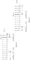
- the CDD basis subset indicator is represented by two values D and D in , where D defines the number of elements of the CDD basis subset, and D in represents the first index of the selected D delay vectors [ d mod ( D in , N 3) , d mod ( D in+1 , N 3) , ..., d mod ( D in+ D -1, N 3) ] from the second codebook.
- CDD basis subset configured by D and D in are shown in Figures 1A and 1B .
- the LDD subset indicator is given by a D -sized bitmap and each bit in the bitmap is associated with a delay vector from the CDD basis subset. A "1" may indicate that the associated delay vector is selected from the CDD basis subset, and a "0" may indicate that the associated delay vector is not selected from the CDD basis subset.
- the LDD subset indicator is given by a ⁇ log 2 D ⁇ D l ⁇ bit indicator.
- the UE for the indication of the payload size of the CDD basis subset indicator in the CSI report part 2, the UE is configured to report the parameter D in CSI report part 1. Furthermore, the UE is configured to report (if available) the parameter D in in CSI part 2.
- the UE for reducing the feedback overhead of the CSI report part 1, the UE is configured with the parameter D by the gNB (and hence not reported in CSI part 1), or the parameter D is a priori known at the UE (and hence not reported in CSI part 1).
- the UE for reducing the feedback overhead of the CSI report part 1, is configured with the parameter(s) D r by the gNB for each possible rank RI of the CSI matrix (and hence not to report the parameter D r in CSI part 1), or the parameter(s) D r are e.g. a priori known at the UE (and hence not reported).
- the UE for reducing the feedback overhead of the CSI report part 1, the UE is configured with the parameter(s) D in,r by the gNB for each possible rank RI of the CSI matrix (and hence not to report the parameter D in,r in CSI part 2), or the parameter(s) D in,r are a priori known at the UE (and hence not reported).
- D ⁇ in , r N 3 ⁇ ⁇ N 3 ′ 2 ⁇ + q , where q ⁇ ⁇ 1,2,.. ⁇ is an integer.
- the UE for reducing the feedback overhead of the CSI report (part 1 and part 2), is configured to receive the CDD basis subset indicator from the gNB, and not to report the CDD basis subset indicator in CSI part 2.
- the CDD basis subset indicator configured by the gNB may be rank-specific, and the gNB configures for each rank RI ⁇ ⁇ 1,2,3,4 ⁇ of the CSI matrix a CDD basis subset indicator.
- the CDD basis subset indicator configured by the gNB is given by a N 3 -sized bitmap, where the bitmap contains D 1's and each bit in the bitmap is associated with a delay vector from the second codebook.
- the CDD basis subset indicator is configured by a ⁇ log 2 N 3 D ⁇ ⁇ bit indicator, where the parameter D indicates the total number of selected delay vectors by the UE across all layers and is configured by the gNB.
- the UE for reducing the feedback overhead of the CSI report (part 1 and part 2), is configured to select the delay vectors for each layer from an a-priori known CDD basis subset indicator (e.g. known by 3GPP standard specification), and not to report the CDD basis subset indicator in CSI part 2.
- an a-priori known CDD basis subset indicator e.g. known by 3GPP standard specification
- the UE for reducing the feedback overhead of the CSI report (part 2), is configured to select the CDD basis subset indicator from a-priori known multiple CDD basis subsets of different sizes and to indicate in the CSI part 1 the size of the selected CDD basis subset.
- the CDD basis subset indicator sets are either higher layer configured or known at the UE (defined by specification).
- the UE for reducing the feedback overhead of the CSI report (part 1 and part 2), is configured to select the CDD basis subset indicator from a-priori known N equal-sized CDD basis subset indicator set(s), and to indicate in the CSI report part 2 the selected CDD basis subset and in the CSI part 1 the size of the selected CDD basis subset.
- the selected CDD basis subset indicator in CSI part 2 may be represented by a ⁇ log 2 N ⁇ bit indicator.
- the UE is configured to perform a N 3 -modulo shift operation on all delay indices of the vectors in the selected DD basis subset of a layer with respect to the delay index associated with the strongest coefficient indicator of the layer. Note that this shift operation has no impact on the performance of the precoder defined by the CSI matrix and the shifted DD basis subset. After this shift operation is applied, the delay index associated with the strongest coefficient is always associated with a known delay index, for example, the first delay index.
- the first delay index does not need to be reported and the DD basis subset indicator for the I-th layer is given by ( N 3 - 1) -sized bitmap, a ⁇ log 2 N 3 D l ⁇ 1 ⁇ bit indicator, or a ⁇ log 2 N 3 ⁇ 1 D l ⁇ 1 ⁇ bit indicator.
- the strongest coefficient indicator may then be represented by a ⁇ log 2 2 U l ⁇ bit indicator to indicate the row of the bitmap associated with the strongest coefficient.
- the UE is configured to perform a D -modulo shift operation on all delay indices of the vectors in the selected LDD basis subset with respect to the delay index associated with the strongest coefficient of the layer. Note that, similar to above, this shift operation has no impact on the performance of the precoder defined by the CSI matrix and the shifted LDD basis subset(s). After this shift operation is applied, the delay index associated with the strongest coefficient is always associated with the first delay index.
- the LDD basis subset indicator for the I-th Layer is given by ( D - 1)-sized bitmap, or a ⁇ log 2 D ⁇ D l ⁇ 1 ⁇ bit indicator, or a ⁇ log 2 D ⁇ ⁇ 1 D l ⁇ 1 ⁇ bit indicator.
- the CDD basis subset indicator may be represented by a ⁇ log 2 N 3 D ⁇ ⁇ 1 ⁇ bit indicator, or a ⁇ log 2 N 3 ⁇ 1 D ⁇ ⁇ 1 ⁇ bit indicator.
- the UE may report a value D ( l ) ' ( ⁇ D ( l ) ) in UCI part 1 indicating that the associated bitmap of the I-th layer contains only D ( l ) ' columns, instead of D ( l ) columns.
- the part of the bitmap containing only zeros is dropped from UCI part 2, In this way, the size of the bitmap is reduced from 2 U ( l ) ⁇ D ( l ) to 2 U ( l ) ⁇ D ( l ) ' and a feedback overhead saving is achieved.
- the value D ( l ) ' may be indicated in UCI part 1.
- D ( l ) ' may be indicated by the UE by a 1-bit indicator for all layers.
- the selected D ( l ) ' may be indicated by the UE by unused code-points of other UCI 1 parameters.
- 46 code-points are un-used and can be used for the indication of the selected value of D ( l ) '. Different examples are provided in the following.
- the UE may be configured to report a FD basis sufficiency indicator in the CSI report, the FD basis sufficiency indicator indicates whether the configuration of the values K (or K 1 or K 2 or K ( l ) ) or D ( l ) or ( D ( l , r ) ) or N 3 is sufficient to calculate the CSI matrix.
- the calculation of the CSI matrix is influenced by aliasing. Also, when the configured values of K (or K 1 or K 2 or K ( l ) ) or D ( l ) or ( D ( l , r ) ) may be too small, the UE may not be able to calculate the CSI matrix.
- the UE may be configured to report the basis sufficiency indicator explicitly in UCI part 1.
- the UE may be configured to explicitly indicate the basis sufficiency indicator using a 1-bit indicator in UCI part 1.
- a '1' of the bit indicator may indicate that the configured values K (or K 1 or K 2 or K ( l ) ) and/or D ( l ) or ( D ( l , r ) ) are sufficient, and a '0' may indicate that the values K (or K 1 or K 2 or K ( l ) ) and/or D ( l ) or ( D ( l,r ) ) are not sufficient.
- the UE may be configured to implicitly indicate the basis sufficiency indication by reporting a zero for the NNZCC in UCI part 1.
- the UE may be configured to implicitly indicate the basis sufficiency indication by reporting a value of two for the NNZCC in UCI part 1.
- the UE when the UE may be configured to indicate via the basis sufficiency indicator in UCI part 1 that if one of the values of K (or K 1 or K 2 or K ( l ) ) and/or D ( l ) or ( D ( l , r ) ) is not sufficient, the UE is configured to drop or partly drop the UCI part 2.
- the UE may be configured to fully drop UCI part 2.
- the UE may be configured to only report the selected SD basis subsets in UCI part 2.
- the UE may be configured to report a selected single SD basis vector along with the selected two non-zero combining coefficients per layer.
- the UE may be configured to report a selected single SD basis vector along with the selected two non-zero combining coefficients only for the first layer.
- the UE may be configured by the gNB with larger values of K (or K 1 or K 2 or K ( l ) ) and/or D ( l ) or ( D ( l , r ) ) or N 3 for future CSI reporting.
- the UE is configured to determine a layer-specific space domain (LSD) basis subset of the selected beam vectors and to indicate the beam vectors in the CSI report (part 2).
- the LSD basis subset indicator is given by a ⁇ log 2 N 1 N 2 U l ⁇ bit indicator for the I-th layer.
- the LSD basis subset indicator ⁇ log 2 N 1 N 2 U ⁇ is identical across all layers and reported once.
- the method performed by the UE comprises:
- the method comprises receiving a configuration from the gNB, said configuration comprising a CSI report configuration including at least one higher-layer parameters, D ( l ) , representing a number of delays per layer, used for the configuration of the precoder matrix or CSI matrix.
- the method further comprises receiving a configuration from the gNB, which configuration includes a single parameter D (0) for a first layer, and deriving the parameter(s) D ( l ) , l > 0 for the remaining layers.
- the configuration of delays is dependent on the Rank Indicator (RI) of the precoder matrix or the CSI matrix.
- the method comprises receiving a configuration from the gNB, said configuration comprising a CSI report configuration including at least one higher-layer parameters, U ( l ) , representing the number of spatial beams for the I-th layer, used for the configuration of the precoder matrix or the CSI matrix.
- the higher layer parameter U is a UE capability; and the method comprises indicating the supported value range for the parameter U to the gNB.
- the method may further comprise using a two-step approach to reduce the overall overhead for reporting the bitmaps of all layers, wherein in a first step, the UE determining determine a joint bitmap of size U g ⁇ D g by the union of individual bitmaps across the layers, and reporting to the gNB the number of '1's in the joint bitmap, and wherein in a second step, reporting to the gNB an indication of the indices of the selected non-zero combining coefficients associated with the joint bitmap.
- the method may further comprise reporting in an UCI (Uplink Control Information) part 2, an indication of selected Spatial Domain, SD, and/or Frequency Domain, FD, basis vectors associated with the joint bitmap.
- UCI Uplink Control Information
- the method may further comprise determining per layer an effective bitmap of size U e l ⁇ D e l , where U e l ⁇ 2 U l and D e l ⁇ D l , , wherein the effective bitmaps are reported in CSI part 2 and wherein each effective bitmap contains only non-zero rows and/or non-zero columns, and indicating in the CSI part 2, an indication of the selected SD basis vectors associated with the effective bitmap per layer and/or an indication of the selected FD basis vectors associated with the effective bitmap per layer.
- the method may further comprise indicating the sizes of the effective bitmaps for all layers in UCI part 1.
- the method further comprises determining a Common Delay Domain (CDD) basis subset of selected delay vectors across all layers, and indicating the delay vectors of the CDD basis subset by a CDD basis subset indicator in the CSI report.
- CDD Common Delay Domain
- the method further comprises indicating the selected delay vectors from the CDD basis subset for each layer by a layer-specific delay domain basis, LDD, subset indicator in the CSI report.
- the method may further comprise performing a N 3 -modulo shift operation on all delay indices of the vectors in a selected Delay Domain (DD) basis subset of a layer with respect to a delay index associated with the strongest coefficient indicator of the layer.
- DD Delay Domain
- the method performed by the UE further comprises selecting and reporting a parameter D in representing a first index of the delay vector in the CDD basis subset, such that the first delay vector associated with index 0 is included in the CDD subset.
- the UE is configured to report the parameter D in using a ⁇ log 2 N 3 ⁇ -bit indicator.
- the value range of the parameter n is reduced from D to d' values, and d' is either higher-layer configured or a priori known or determined by the UE for given parameters N 3 and/or D , and wherein the value n is reported by the UE using a ⁇ log 2 d ′ ⁇ -bit indicator.
- the value range of the parameter q is either higher-layer configured, or fixed and a priori known to the UE or determined by the UE based on the configured N 3 and D values.
- each of the d' codepoints is represented by a ⁇ log 2 d ′ ⁇ -bit indicator, where the first codepoint is represented by ⁇ log 2 d ′ ⁇ -zeros and associated with the smallest integer value in the value range of q, and wherein the remaining values in the pre-defined set of d' values are mapped to codepoints in an increasing order.
- the zero value is mapped to the first codepoint, represented by ⁇ log 2 d ′ ⁇ - zeros.
- the reporting of the parameter D in may be dependent on the transmission rank, and for a low rank transmission, the parameter D in may be fixed, hence not reported.
- the value of D in is reported when the transmission rank is larger than a threshold value.
- the value of D in is reported when the configured value of D is smaller than a threshold value.
- the parameter D defining the CDD basis subset size, depends on the transmission rank, wherein the CDD basis subset size increases with increasing transmission rank.
- the size of the CDD basis subset D depends on the configured number of Spatial Domain (SD) basis vectors, where the value of D configured for larger number of SD basis vectors is smaller than the value of D configured for smaller number of SD basis vectors.
- SD Spatial Domain
- the CDD basis subset is defined by two values D and D in , where D denotes the number of elements in the CDD basis subset, and D in represents the first index of the selected D delay vectors.
- the common delay domain, CDD, basis subset indicator indicating a common continuous subset of delay vectors across all layers is defined by the parameter D in representing the first index of the delay vector of the CDD basis subset and the parameter D representing the number of delay vectors of the CDD basis subset.
- the UE selects the starting index of the CDD basis subset D in from the N 3 -sized set [0,1, ..., N 3 - 1].
- the UE is configured to report the selected value of D in using a ⁇ log 2 N 3 ⁇ -bit indicator.
- the UE is configured to select and report the parameter D in such that the FD basis vector associated with the SCI (which is not necessarily the first FD basis vector) is included in the CDD basis subset.
- the value range of D in is reduced from N 3 to D values and is given by a function of N 3 and D , and is defined by equation (1): mod d SCI ⁇ D ⁇ + 1 + n , N 3 , n ⁇ 0 , D ⁇ ⁇ 1 where d SCI is the index of the FD basis vector associated with the SCI.
- the FD basis vector associated with the strongest combining coefficient per layer is cyclically shifted to the FD basis vector index 0.
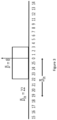
- the first FD basis vector (corresponding to index 0) is associated with the strongest combining coefficient. Therefore, according to an embodiment, the parameter D in is selected by the UE in a way that the CDD basis subset contains the first FD basis vector which is associated with index 0, see Figure 3 .
- the FD basis vector 0 is included when D in is given by one of the values from the set [19,20,21,22,23,24,25,0].
- Table 1 shows the corresponding value range of D in for different values of N 3 and D . It can be observed that the value range of D in is dependent on N 3 and D .
- Table 1 Values of D in for different combinations of N 3 and D N 3 D
- Values of D in 26 6 [0, 21, 22, 23, 24, 25] 8 [0, 19, 20, 21, 22, 23, 24, 25] 10 [0, 17,18,19, 20, 21, 22, 23, 24, 25] 12 [0, 15, 16, 17, 18, 19, 20, 21, 22, 23, 24, 25] 38 8 [0, 33, 34, 35, 36, 37] 10 [0, 29, 30, 31, 32, 33, 34, 35, 36, 37] 13 [0, 26, 27, 28, 29, 30, 31, 32, 33, 34, 35, 36, 37] 16 [0,23, 24, 25, 26, 27, 28, 29, 30, 31, 32, 33, 34, 35, 36, 37]
- the UE when the UE is configured to perform a cyclic shift operation on the selected combining coefficients and the selected FD basis vectors per layer with respect to the FD basis vector that is associated with the SCI, the UE is configured to select and report the parameter D in such that the first FD basis vector (associated with index 0) is included in the CDD basis subset.
- the value range of D in is reduced from N 3 to D values and is given by a function of N 3 and D , and is defined by equation (2): mod N 3 ⁇ D ⁇ + 1 + n , N 3 , n ⁇ 0 , D ⁇ ⁇ 1
- the UE may be configured to report D in using a ⁇ log 2 D ⁇ ⁇ -bit indicator.
- the selected value of n is reported using a ⁇ log 2 D ⁇ ⁇ -bit indicator.
- the size of the bit indicator for reporting the value of D in depends on the CDD subset size D .
- the feedback overhead for reporting D in increases with increasing values of D .
- the value range of D in may be limited to d' values, such that the corresponding bit indicator for D in has a fixed size.
- the value of the starting index of the CDD subset D in is reported using a ⁇ log 2 d ′ ⁇ -bit indicator.
- the value range of D in is defined by d' values, where the parameter d' is either higher-layer configured or a priori known or determined by the UE for given parameters N 3 and/or D .
- the selected D in values are spread over the entire allowable range of D in
- the indices that lie in the center of the allowable range of D in are selected with higher probability than the remaining indices.
- the value range of D in may therefore be defined by those values that are selected with high probability. It can also be observed that for the values of D in that are selected with high probability, the CDD basis subset is centered with FD index 0 that is associated with the strongest coefficient.
- the value range of the parameter n is reduced from D to d' values, and d' is either higher-layer configured or a priori known or determined by the UE for given parameters N 3 and/or D , and wherein the value n is reported by the UE using a ⁇ log 2 d ′ ⁇ -bit indicator.
- the parameter d' is either higher-layer configured or a priori known or determined by the UE for given parameters N 3 and/or D .
- d' 2 d" , where d " ⁇ Z + .
- d' is an even numbered value.
- d' D .
- the value range of the parameter q may be higher layer configured, or fixed and a priori known to the UE or determined by the UE based on the configured N 3 and D values.
- the UE may be configured to report the selected value of q to the gNB, instead of reporting the parameter D in .
- the gNB determines the value of D in from the reported value of q based on equation (2).
- Each value of q selected from the pre-defined set of d' values is mapped to a codepoint, represented by a value of a ⁇ log 2 d ′ ⁇ -bit indicator.
- a specific mapping rule is required. In the following, two mapping rules are proposed.
- each of the d' codepoints is represented by a ⁇ log 2 d ′ ⁇ -bit indicator, where the first codepoint is represented by ⁇ log 2 d ′ ⁇ -zeros and associated with the smallest integer value in the value range of q.
- the remaining values in the pre-defined set of d' values are mapped to codepoints in an increasing order, as shown in Table 2, option A.
- the zero value is mapped to the first codepoint, represented by ⁇ log 2 d ′ ⁇ -zeros.
- the remaining values in the pre-defined set of d' values are mapped to codepoints in an increasing order, as shown in Table 2 below, option B.
- Option A q Codepoint q Codepoint -1 00 0 00 0 01 1 01 1 10 2 10 2 11 -1 11
- the UE in order to save feedback overhead for the reporting of the parameter D in , the UE may be configured to report the parameter q based on equation (3) or n based on equation (1) or (2), that determines the parameter D in .
- the reporting of either the parameter n or q may depend on the parameter D .
- the value of n may be reported when D is less than a threshold value, and otherwise the value of q may be reported.
- the UE may report the selected value of n , otherwise, it reports the selected value of q.
- the delay spread of the corresponding beam-formed channel impulse response associated with a layer of the precoder matrix becomes larger, thus requiring a larger CDD basis subset size of the precoder matrix for covering the delay spread of the corresponding beam-formed channel impulse response. Therefore, the size of the CDD basis subset D depends on the transmission rank, and the value of D may increase with increasing transmission rank. Moreover, for a low rank transmission, the selected value of D in from the pre-defined value range of q, given by equation (2), does not significantly affect the performance. Therefore, for low-rank transmission, D in can be fixed.
- the reporting of the parameter D in may be dependent on the transmission rank.
- the parameter D in may be fixed (hence not reported).
- R' 1.
- R' ⁇ ⁇ 1,2 ⁇ .
- the reporting of the parameter D in may be performed when the transmission rank is larger than a threshold.
- the reporting of the parameter D in may depend on the configured parameter D .
- the value of D in (or the associated parameter n or q) may be reported when the configured value of D is smaller than a threshold value, otherwise the value of D in (or the associated parameter n or q) is fixed (and hence not reported).
- the delay spread of the corresponding beam-formed channel impulse response associated with a layer of the precoder matrix becomes larger, thus requiring a larger CDD basis subset size of the precoder matrix for covering the delay spread of the corresponding beam-formed channel impulse response. Therefore, according to an embodiment, the size of the CDD basis subset D depends on the transmission rank, and the value of D may increase with increasing transmission rank.
- the parameter D defining the CDD basis subset size, may depend on the transmission rank.
- the size of the CDD basis subset configured for a rank- R' transmission may always be equal or smaller than the size of the CDD basis subset configured for a rank- R" transmission, where R' ⁇ R".
- D 10.
- the delay impulse response associated with an SD beam is associated with only one or few channel cluster(s) of the radio channel, where each channel cluster is characterized by a single mean delay.
- the configured CDD basis subset D depends on the configured number of SD beams U or U ( l ) .
- the delay spread of the corresponding beam-formed channel impulse response becomes larger, thus requiring a larger CDD basis subset for covering the delays of the precoder matrix.
- the size of the CDD basis subset D depends on the configured number of SD basis vectors.
- the configured CDD basis subset size D increases with increasing values of U or U ( l ) .
- the value of D configured for larger number of SD basis vectors may be smaller than the value of D configured for smaller number of SD basis vectors.
- the SCI may be configured to be rank-dependent. For example, for a rank-1 transmission, the SCI is given by a ⁇ log 2 K NZ ⁇ -bit indicator, and for a higher rank (RI>1) transmission, the SCI is given by a ⁇ log 2 2 U ⁇ -bit indicator.
- the UE is configured to use CDD basis subset-based reporting when the configured number of CQI subbands N SB is greater than a threshold value. For example, N SB > 13.
- the UE is configured to use the CDD basis subset-based reporting when the total number of subbands N 3 is greater than a threshold value. For example, N 3 > 19.
- the UE When the UE is enforced to perform a cyclic shift operation on the selected combining coefficients and the selected DD basis vectors per layer with respect to the FD basis vector associated with the SCI, e.g., the SCI is given by a ⁇ log 2 2 U ⁇ - bit indicator, a reporting of a '1' in the bitmap used to indicate the position of the strongest coefficient is redundant. Therefore, the size of the bitmap reported by the UE can be reduced by a single bit per layer.
- the complete bitmap of size 2 U ( l ) D ( l ) is required to indicate the SD basis vector index and FD basis vector index of the SCI.
- the size of the bitmap associated with each layer can be reduced from to 2 U ( l ) D ( l ) to 2 U ( l ) D ( l ) - 1 bits.
- the size of the bitmap may be rank-dependent as well.
- the SCI is given by a ⁇ log 2 K NZ ⁇ -bit indicator, and the associated bitmap has a size of 2 U ( l ) D ( l )
- the SCI is given by a ⁇ log 2 2 U ⁇ -bit indicator and the size of the bitmap per layer is given by 2 U ( l ) D ( l ) - 1.
- the indicator associated with the reporting of the selected NNZCC across all layers in CSI part 1 is given by a ⁇ log 2 g ⁇ -bit indicator.
- the particular value of g may depend on the transmission rank.
- the ⁇ log 2 g ⁇ -bit indicator indicating the number of non-zero combining coefficients for the CSI matrix of the CSI report in CSI part 1 is rank-dependent.
- K 0 denotes the maximum NNZCC per layer, which is higher layer configured to the UE by the gNB.
- the amplitude and phase information associated with the strongest coefficient of each layer is normalized to 1 and hence not reported. Therefore, the UE may indicate only the NNZCC across all layers for which the amplitude and phase information is reported in CSI part 2.
- the selected D ( l ) ' may be indicated by the UE by unused code-points of other UCI 1 parameters.
- the unused code-points used for the indication of the number of non-zero combining coefficients may be used to report in addition the 1-bit indicator for D ( l ) ' for all layers.
- the 44+RI un-used code-points are used for the indication of the selected value of D ( l ) '.
- UE 300 comprises a processor 310 or processing circuit or a processing module or a processor or means 310; a receiver circuit or receiver module 340; a transmitter circuit or transmitter module 350; a memory module 320 a transceiver circuit or transceiver module 330 which may include the transmitter circuit 350 and the receiver circuit 340.
- the UE 300 further comprises an antenna system 360 which includes antenna circuitry for transmitting and receiving signals to/from at least the UE.
- the antenna system employs beamforming as previously described.
- the UE 300 may operate in any radio access technology including 2G, 3G, 4G or LTE, LTE-A, 5G, WLAN, and WiMax etc. that support beamforming technology.
- the processing module/circuit 310 includes a processor, microprocessor, an application specific integrated circuit (ASIC), field programmable gate array (FPGA), or the like, and may be referred to as the "processor 310."
- the processor 310 controls the operation of the UE 300 and its components.
- Memory (circuit or module) 320 includes a random access memory (RAM), a read only memory (ROM), and/or another type of memory to store data and instructions that may be used by processor 310.
- RAM random access memory
- ROM read only memory
- the UE 300 in one or more embodiments includes fixed or programmed circuitry that is configured to carry out the operations in any of the embodiments disclosed herein.
- the UE 300 includes a microprocessor, microcontroller, DSP, ASIC, FPGA, or other processing circuitry that is configured to execute computer program instructions from a computer program stored in a non-transitory computer-readable medium that is in, or is accessible to the processing circuitry.
- non-transitory does not necessarily mean permanent or unchanging storage, and may include storage in working or volatile memory, but the term does connote storage of at least some persistence.
- the execution of the program instructions specially adapts or configures the processing circuitry to carry out the operations disclosed herein including any one of method claims 1-11. Further, it will be appreciated that the UE 300 may comprise additional components not shown in Figure 5 .
- the method comprises: transmitting to a UE a radio signal via a MIMO channel, wherein the radio signal contains at least one DL, reference signal according to a DL reference signal configuration, for enabling the UE to estimate said MIMO channel based on said received at least one DL reference signal for configured subbands and calculate a precoder matrix or a CSI matrix for a number of antenna ports of the gNB and configured subbands; the precoder matrix being based on a first codebook and on a second codebook and a set of combining coefficients for complex scaling/combining one or more of vectors selected from the first codebook and the second codebook; where, the first codebook contains one or more transmit-side spatial beam components of the precoder matrix, the second codebook contains one or more delay components of the precoder matrix, and receiving, from the UE, a CSI feedback report and/or a PMI and/or a PMI/RI, used to
- the gNB comprises a processor or processing circuit or a processing module or a processor or means; a receiver circuit or receiver module; a transmitter circuit or transmitter module; a memory module a transceiver circuit or transceiver module which may include the transmitter circuit and the receiver circuit.
- the gNB further comprises an antenna system which includes antenna circuitry for transmitting and receiving/transmitting signals to/from at least the UE.
- the antenna system employs beamforming as previously described.
- the gNB may operate in any radio access technology including 2G, 3G, 4G or LTE, LTE-A, 5G, WLAN, and WiMax etc. that support beamforming technology.
- the processing module/circuit includes a processor, microprocessor, an application specific integrated circuit (ASIC), field programmable gate array (FPGA), or the like, and may be referred to as the "processor.”
- the processor controls the operation of the gNB and its components.
- Memory includes a random access memory (RAM), a read only memory (ROM), and/or another type of memory to store data and instructions that may be used by processor.
- RAM random access memory
- ROM read only memory
- the gNB in one or more embodiments includes fixed or programmed circuitry that is configured to carry out the operations in any of the embodiments disclosed herein.
- the gNB includes a microprocessor, microcontroller, DSP, ASIC, FPGA, or other processing circuitry that is configured to execute computer program instructions from a computer program stored in a non-transitory computer-readable medium that is in, or is accessible to the processing circuitry.
- non-transitory does not necessarily mean permanent or unchanging storage, and may include storage in working or volatile memory, but the term does connote storage of at least some persistence.
- the execution of the program instructions specially adapts or configures the processing circuitry to carry out the operations disclosed in this disclosure. Further, it will be appreciated that the gNB may comprise additional components.
- the word "comprise” or “comprising” has been used in a non-limiting sense, i.e. meaning “consist at least of”. Although specific terms may be employed herein, they are used in a generic and descriptive sense only and not for purposes of limitation.
- the embodiments herein may be applied in any wireless systems including GSM, 3G or WCDMA, LTE or 4G, LTE-A (or LTE-Advanced), 5G, WiMAX, WiFi, satellite communications, TV broadcasting etc. that may employ beamforming technology.
Landscapes
- Engineering & Computer Science (AREA)
- Computer Networks & Wireless Communication (AREA)
- Signal Processing (AREA)
- Physics & Mathematics (AREA)
- Mathematical Physics (AREA)
- Power Engineering (AREA)
- Radio Transmission System (AREA)
- Mobile Radio Communication Systems (AREA)
- Alarm Systems (AREA)
- Arrangements For Transmission Of Measured Signals (AREA)
- Circuits Of Receivers In General (AREA)
Claims (12)
- Procédé réalisé par un Équipement Utilisateur, UE, le procédé comprenant :- la réception (201) d'un noeud de réseau, gNB, d'un signal radio via un canal à entrées multiples et sorties multiples, MIMO, le signal radio contenant au moins un signal de référence de Liaison Descendante, DL, selon une configuration de signal de référence DL ;- l'estimation (202) dudit canal MIMO sur la base dudit au moins un signal de référence DL reçu pour des sous-bandes configurées ;- le calcul (203) d'une matrice de précodeur ou d'une matrice d'Informations d'État de Canal, CSI, pour un certain nombre de ports d'antenne du gNB et de sous-bandes configurées, N 3; la matrice de précodeur étant basée sur un premier livre de codes et sur un second livre de codes et un ensemble de coefficients de combinaison pour une mise à l'échelle/combinaison complexe d'un ou plusieurs vecteurs sélectionnés parmi le premier livre de codes et le second livre de codes ;
où,- le premier livre de codes contient une ou plusieurs composantes de faisceau spatial côté transmission de la matrice de précodeur ou de la matrice CSI,- le second livre de codes contient une ou plusieurs composantes de retard de la matrice de précodeur ou de la matrice CSI,- la détermination d'un sous-ensemble de base de domaine de retard commun, CDD, des vecteurs sélectionnés associés aux composantes de retard sur toutes les couches de la matrice de précodeur ou de la matrice CSI, le sous-ensemble de base CDD étant défini par un paramètreD représentant le nombre d'éléments du sous-ensemble de base CDD, et un paramètreD in représentant le premier indice desD vecteurs de retard du second livre de codes, la plage de valeurs du paramètreD in est réduite de N 3 àD valeurs ; et- le rapport (204), au gNB, d'un rapport de rétroaction CSI et/ou d'un Indicateur de Matrice de Précodeur, PMI, et/ou d'un indicateur de PMI/Rang, PMI/RI, utilisés pour indiquer la matrice de précodeur ou la matrice CSI pour les ports d'antenne configurés et les sous-bandes configurées ; dans lequel les vecteurs sélectionnés à partir du sous-ensemble de base CDD sont indiqués dans le rapport, pour chaque couche, par un indicateur de sous-ensemble de base de domaine de retard spécifique à la couche, LDD ; et le paramètreD in est reporté au gNB. - Procédé selon la revendication 1 comprenant la réception d'une configuration depuis le gNB, ladite configuration comprenant une configuration de rapport CSI comportant au moins un paramètre de couche supérieure, D (l), représentant un nombre de retards par couche utilisé pour la configuration de la matrice de précodeur ou de la matrice CSI.
- Procédé selon la revendication 2 dans lequel le nombre de retards D (l) est indépendant de la couche et identique pour toutes les couches, de sorte que D (l) =D, et configurant l'UE avec un seul paramètre D pour la configuration de la matrice de précodeur ou de la matrice CSI.
- Procédé selon la revendication 1, comprenant la réalisation d'une opération de décalage module N 3 sur tous les indices de retard associés aux vecteurs de retard sélectionnés indiqués par l'indicateur de sous-ensemble de base LDD et sur tous les coefficients de combinaison non nuls d'une couche par rapport à un indice de retard associé à l'indicateur de coefficient le plus fort, SCI, de la couche.
- Procédé selon la revendication 1 ou la revendication 4, dans lequel le paramètre
D in est sélectionné, de sorte que le premier vecteur de retard associé à l'indice 0 soit inclus dans le sous-ensemble de base CDD. - Procédé selon la revendication 1 ou la revendication 4 ou la revendication 5, dans lequel la plage de valeurs du paramètre
D in est définie par :
D in = mod(dSCI -D + 1 + n, N 3), n ∈ [0,D - 1] , où dSCI est l'indice du vecteur de base de Domaine Fréquentiel, FD, associé au SCI, et l'UE est configuré pour rapporterD in en utilisant un indicateur
- Procédé selon la revendication 1 ou la revendication 4 ou la revendication 5, dans lequel la plage de valeurs du paramètre
D in est définie par :
D in = mod(N 3 -D + 1 + n,N 3),n ∈ [0,D - 1], et l'UE est configuré pour rapporterD in en utilisant un indicateur
- Procédé selon l'une quelconque des revendications précédentes, dans lequel le paramètre
D , définissant la taille du sous-ensemble de base CDD, dépend du rang de transmission. - Procédé selon la revendication 4, dans lequel le SCI est configuré pour être dépendant du rang ; dans lequel pour une transmission RI=1, le SCI est donné par un indicateur


- Équipement Utilisateur, UE, (300) comprenant un processeur (310) et une mémoire (320), ladite mémoire (320) contenant des instructions exécutables par ledit processeur (310), moyennant quoi ledit UE (300) fonctionne pour réaliser l'un quelconque des objets des revendications de procédé 1 à 9.
- Procédé réalisé par un noeud de réseau, gNB, le procédé comprenant :- la transmission, à un Équipement Utilisateur, UE, d'un signal radio via un canal à entrées multiples et sorties multiples, MIMO, le signal radio contenant au moins un signal de référence de Liaison descendante, DL, selon une configuration de signal de référence DL ; pour permettre à l'UE de :- estimer ledit canal MIMO sur la base dudit au moins un signal de référence DL reçu pour des sous-bandes configurées ;- calculer (203) une matrice de précodeur ou une matrice d'Informations d'État de Canal, CSI, pour un certain nombre de ports d'antenne du gNB et de sous-bandes configurées, N 3; la matrice de précodeur étant basée sur un premier livre de codes et sur un second livre de codes et un ensemble de coefficients de combinaison pour une mise à l'échelle/combinaison complexe d'un ou plusieurs vecteurs sélectionnés parmi le premier livre de codes et le second livre de codes ;
où,- le premier livre de codes contient une ou plusieurs composantes de faisceau spatial côté transmission de la matrice de précodeur ou de la matrice CSI,- le second livre de codes contient une ou plusieurs composantes de retard de la matrice de précodeur ou de la matrice CSI ;- déterminer un sous-ensemble de base de domaine de retard commun, CDD, des vecteurs sélectionnés associés aux composantes de retard sur toutes les couches de la matrice de précodeur ou de la matrice CSI, le sous-ensemble de base CDD étant défini par un paramètreD représentant le nombre d'éléments du sous-ensemble de base CDD, et un paramètreD in représentant le premier indice des vecteurs de retardD du second livre de codes, la plage de valeurs du paramètreD in est réduite de N 3 àD valeurs ; et- recevoir, depuis l'UE, un rapport de rétroaction CSI et/ou un Indicateur de Matrice de Précodeur, PMI et/ou un Indicateur de PMI/Rang, PMI/RI, utilisés pour indiquer la matrice de précodeur ou la matrice CSI pour les ports d'antenne configurés et les sous-bandes configurées ; dans lequel les vecteurs sélectionnés à partir du sous-ensemble de base CDD sont indiqués dans le rapport, pour chaque couche, par un indicateur de sous-ensemble de base de domaine de retard spécifique à la couche, LDD ; et le paramètreD in est rapporté au gNB. - Noeud de réseau comprenant un processeur et une mémoire, ladite mémoire contenant des instructions exécutables par ledit processeur, moyennant quoi ledit noeud de réseau est configuré pour réaliser le sujet de la revendication 11.
Priority Applications (1)
| Application Number | Priority Date | Filing Date | Title |
|---|---|---|---|
| EP23179674.9A EP4236103B1 (fr) | 2019-05-02 | 2020-04-14 | Procédé et appareil d'amélioration d'indication de sous-ensemble de base pour un reporting csi basé sur deux livres de codes |
Applications Claiming Priority (3)
| Application Number | Priority Date | Filing Date | Title |
|---|---|---|---|
| EP19172422.8A EP3734852A1 (fr) | 2019-05-02 | 2019-05-02 | Procédés et appareils de reporting csi dans un système de communication sans fil |
| EP19191235.1A EP3734853A1 (fr) | 2019-05-02 | 2019-08-12 | Procédé et appareil d'amélioration d'indication de sous-ensemble de base pour un reporting csi basé sur deux livres de codes |
| PCT/EP2020/060397 WO2020221581A1 (fr) | 2019-05-02 | 2020-04-14 | Procédés et appareils d'amélioration sur la base d'une indication de sous-ensemble destinée à un rapport de csi basé sur deux livres de codes |
Related Child Applications (1)
| Application Number | Title | Priority Date | Filing Date |
|---|---|---|---|
| EP23179674.9A Division EP4236103B1 (fr) | 2019-05-02 | 2020-04-14 | Procédé et appareil d'amélioration d'indication de sous-ensemble de base pour un reporting csi basé sur deux livres de codes |
Publications (2)
| Publication Number | Publication Date |
|---|---|
| EP3963732A1 EP3963732A1 (fr) | 2022-03-09 |
| EP3963732B1 true EP3963732B1 (fr) | 2023-07-05 |
Family
ID=66397071
Family Applications (6)
| Application Number | Title | Priority Date | Filing Date |
|---|---|---|---|
| EP19172422.8A Withdrawn EP3734852A1 (fr) | 2019-05-02 | 2019-05-02 | Procédés et appareils de reporting csi dans un système de communication sans fil |
| EP19191235.1A Withdrawn EP3734853A1 (fr) | 2019-05-02 | 2019-08-12 | Procédé et appareil d'amélioration d'indication de sous-ensemble de base pour un reporting csi basé sur deux livres de codes |
| EP25156765.7A Pending EP4597873A3 (fr) | 2019-05-02 | 2020-04-14 | Procédés et appareils de rapport de csi dans un système de communication sans fil |
| EP23179674.9A Active EP4236103B1 (fr) | 2019-05-02 | 2020-04-14 | Procédé et appareil d'amélioration d'indication de sous-ensemble de base pour un reporting csi basé sur deux livres de codes |
| EP20717208.1A Active EP3963732B1 (fr) | 2019-05-02 | 2020-04-14 | Procédé et appareil d'amélioration d'indication de sous-ensemble de base pour un reporting csi basé sur deux livres de codes |
| EP20717210.7A Active EP3963733B1 (fr) | 2019-05-02 | 2020-04-14 | Procédé et appareil d'amélioration d'indication de sous-ensemble de base pour un reporting csi basé sur deux livres de codes |
Family Applications Before (4)
| Application Number | Title | Priority Date | Filing Date |
|---|---|---|---|
| EP19172422.8A Withdrawn EP3734852A1 (fr) | 2019-05-02 | 2019-05-02 | Procédés et appareils de reporting csi dans un système de communication sans fil |
| EP19191235.1A Withdrawn EP3734853A1 (fr) | 2019-05-02 | 2019-08-12 | Procédé et appareil d'amélioration d'indication de sous-ensemble de base pour un reporting csi basé sur deux livres de codes |
| EP25156765.7A Pending EP4597873A3 (fr) | 2019-05-02 | 2020-04-14 | Procédés et appareils de rapport de csi dans un système de communication sans fil |
| EP23179674.9A Active EP4236103B1 (fr) | 2019-05-02 | 2020-04-14 | Procédé et appareil d'amélioration d'indication de sous-ensemble de base pour un reporting csi basé sur deux livres de codes |
Family Applications After (1)
| Application Number | Title | Priority Date | Filing Date |
|---|---|---|---|
| EP20717210.7A Active EP3963733B1 (fr) | 2019-05-02 | 2020-04-14 | Procédé et appareil d'amélioration d'indication de sous-ensemble de base pour un reporting csi basé sur deux livres de codes |
Country Status (7)
| Country | Link |
|---|---|
| US (4) | US20220224391A1 (fr) |
| EP (6) | EP3734852A1 (fr) |
| JP (2) | JP7550170B2 (fr) |
| KR (3) | KR20220003094A (fr) |
| CN (2) | CN114128161B (fr) |
| ES (2) | ES2952647T3 (fr) |
| WO (2) | WO2020221582A1 (fr) |
Families Citing this family (32)
| Publication number | Priority date | Publication date | Assignee | Title |
|---|---|---|---|---|
| US12407391B2 (en) | 2018-12-22 | 2025-09-02 | Koninklijke Philips N.V. | Methods and apparatuses for codebook restriction for type-II feedback reporting and higher layer configuration and reporting for linear combination codebook in a wireless communications network |
| US11949483B2 (en) * | 2021-02-01 | 2024-04-02 | Koninklijke Philips N.V. | Methods and apparatuses for codebook restriction for type-II feedback reporting and higher layer configuration and reporting for linear combination codebook in a wireless communications network |
| AU2019438745B2 (en) * | 2019-04-04 | 2023-02-02 | Nokia Technologies Oy | Uplink control information |
| EP3734852A1 (fr) * | 2019-05-02 | 2020-11-04 | Fraunhofer Gesellschaft zur Förderung der angewandten Forschung e.V. | Procédés et appareils de reporting csi dans un système de communication sans fil |
| US11757855B2 (en) * | 2019-05-02 | 2023-09-12 | Electronics And Telecommunications Research Institute | Method and apparatus for communications using secret key in communication system |
| JP7431231B2 (ja) * | 2019-06-10 | 2024-02-14 | 株式会社Nttドコモ | 端末、無線通信方法及びシステム |
| KR102815277B1 (ko) * | 2019-11-29 | 2025-05-29 | 지티이 코포레이션 | 무선 채널 상태 정보 피드백을 압축하는 방법 |
| US11888562B2 (en) * | 2020-01-03 | 2024-01-30 | Samsung Electronics Co., Ltd. | Method and apparatus for reciprocity based CSI-RS transmission and reception |
| US12413280B2 (en) * | 2020-02-07 | 2025-09-09 | Ntt Docomo, Inc. | Method of sounding reference signal (SRS)-assisted SD beam and FD vector reporting for type II channel state information (CSI) |
| US20230361831A1 (en) * | 2020-06-26 | 2023-11-09 | Lenovo (Singapore) Pte. Ltd. | Determining channel state information reference signals |
| EP4179638A1 (fr) * | 2020-07-10 | 2023-05-17 | Telefonaktiebolaget LM Ericsson (publ) | Signalisation pour aider à une rétroaction de csi de type ii nr améliorée |
| US12088378B2 (en) * | 2020-09-18 | 2024-09-10 | Qualcomm Incorporated | Low overhead and high accuracy channel state feedback using neural networks |
| US20220124537A1 (en) * | 2020-10-20 | 2022-04-21 | Samsung Electronics Co., Ltd. | Method and apparatus for csi reporting based on a port selection codebook |
| EP4002713A1 (fr) * | 2020-11-23 | 2022-05-25 | Fraunhofer-Gesellschaft zur Förderung der angewandten Forschung e.V. | Rapports csi basés sur un livre de codes de combinaison linéaire |
| CN114531183A (zh) | 2020-11-23 | 2022-05-24 | 华为技术有限公司 | 信道矩阵的确定方法、装置及系统 |
| CN114598365B (zh) * | 2020-12-01 | 2023-10-17 | 维沃移动通信有限公司 | 传输方法、装置、设备及可读存储介质 |
| US20220190897A1 (en) * | 2020-12-14 | 2022-06-16 | Samsung Electronics Co., Ltd. | Codebook for distributed mimo transmission |
| WO2022144778A1 (fr) | 2020-12-28 | 2022-07-07 | Telefonaktiebolaget Lm Ericsson (Publ) | Procédés de réduction de surdébit de rétroaction d'informations d'états de canaux de type ii de nr à l'aide de réciprocité d'angles et de retards |
| US12047145B2 (en) * | 2021-02-03 | 2024-07-23 | Samsung Electronics Co., Ltd. | Method and apparatus for CSI reporting |
| CN117356039A (zh) * | 2021-03-19 | 2024-01-05 | 弗劳恩霍夫应用研究促进协会 | 基于线性组合端口选择码本的csi省略方法和装置 |
| US12267137B2 (en) | 2021-05-11 | 2025-04-01 | Nokia Technologies Oy | Reporting channel state information (CSI) precoding matrix indicator (PMI) |
| JP7644267B2 (ja) * | 2021-05-11 | 2025-03-11 | ノキア テクノロジーズ オサケユイチア | プリコーディング情報 |
| CN115706597A (zh) * | 2021-08-05 | 2023-02-17 | 华为技术有限公司 | 一种信息反馈方法以及相关装置 |
| US12549236B2 (en) * | 2021-11-04 | 2026-02-10 | Apple Inc. | UE capability reporting |
| WO2023184147A1 (fr) * | 2022-03-29 | 2023-10-05 | Qualcomm Incorporated | Sélection et quantification de coefficients du domaine temporel par le biais d'un livre de codes etype-ii étendu |
| EP4515765A4 (fr) * | 2022-04-28 | 2025-06-18 | NEC Corporation | Procédés, dispositifs, et support lisible par ordinateur pour des communications |
| EP4533682A4 (fr) * | 2022-06-03 | 2026-01-21 | Qualcomm Inc | Sélection sur une base de domaine temporel par faisceau pour livre de codes d'informations d'état de canal |
| CN119856458A (zh) * | 2022-09-09 | 2025-04-18 | 华为技术有限公司 | 用于支持无线网络中的多层传输的系统和方法 |
| CN118120152A (zh) * | 2022-09-29 | 2024-05-31 | 北京小米移动软件有限公司 | 指示上报方法及其装置 |
| EP4652697A4 (fr) * | 2023-01-20 | 2026-01-07 | Nec Corp | Procédés, dispositifs et support de communication |
| WO2024255825A1 (fr) * | 2023-06-16 | 2024-12-19 | Mediatek Inc. | Rétroaction et compression de canal direct sur une dimension d'antenne rx |
| US20250132792A1 (en) * | 2023-10-24 | 2025-04-24 | Samsung Electronics Co., Ltd. | Csi reporting |
Family Cites Families (43)
| Publication number | Priority date | Publication date | Assignee | Title |
|---|---|---|---|---|
| US7885354B2 (en) * | 2004-04-02 | 2011-02-08 | Rearden, Llc | System and method for enhancing near vertical incidence skywave (“NVIS”) communication using space-time coding |
| US20110059703A1 (en) * | 2007-09-28 | 2011-03-10 | Nokia Corporation | User equipment-initiated precoding subset restriction for communication systems |
| US8588799B2 (en) * | 2009-11-04 | 2013-11-19 | Alcatel Lucent | Method and apparatus for processing downlink communication and corresponding assisting method and apparatus |
| US8982978B2 (en) * | 2010-08-23 | 2015-03-17 | Lg Electronics Inc. | Method and apparatus for transceiving a precoded signal in a multiple antenna supported wireless communication system |
| JP2012100254A (ja) * | 2010-10-06 | 2012-05-24 | Marvell World Trade Ltd | Pucchフィードバックのためのコードブックサブサンプリング |
| JP6026082B2 (ja) * | 2011-04-05 | 2016-11-16 | シャープ株式会社 | 端末、基地局、通信方法および集積回路 |
| US9413442B2 (en) * | 2011-10-10 | 2016-08-09 | Lg Electronics Inc. | Method and apparatus for reporting channel state information in a wireless communication system |
| BR112014011040B1 (pt) * | 2011-11-07 | 2023-03-28 | Motorola Mobility Llc | Método e aparelho para retorno de csi para esquemas de processamento conjunto em um sistema de comunicação de multiplexação com divisão de frequência ortogonal com transmissão de ponto múltiplo coordenado |
| JP5990815B2 (ja) * | 2011-11-07 | 2016-09-14 | シャープ株式会社 | 基地局、端末、通信システムおよび通信方法 |
| US8942302B2 (en) * | 2012-12-20 | 2015-01-27 | Google Technology Holdings LLC | Method and apparatus for antenna array channel feedback |
| US8976884B2 (en) * | 2012-12-20 | 2015-03-10 | Google Technology Holdings LLC | Method and apparatus for antenna array channel feedback |
| US9312945B2 (en) * | 2013-02-28 | 2016-04-12 | Lg Electronics Inc. | Method for reporting downlink channel state and apparatus therefor |
| JP6325652B2 (ja) * | 2013-04-29 | 2018-05-16 | エルジー エレクトロニクス インコーポレイティド | 無線通信システムにおいてチャネル状態情報送信方法及び装置 |
| EP3178258B1 (fr) * | 2014-08-07 | 2019-10-30 | Telefonaktiebolaget LM Ericsson (publ) | Alignement d'écarts de mesurage et de signaux de découverte |
| US9825742B2 (en) * | 2014-10-03 | 2017-11-21 | Samsung Electronics Co., Ltd. | Codebook design and structure for advanced wireless communication systems |
| US9698881B2 (en) * | 2014-11-14 | 2017-07-04 | Telefonaktiebolaget Lm Ericsson (Publ) | Feedback channel transmission and detection in multi antenna wireless communication systems |
| US9680535B2 (en) * | 2015-01-16 | 2017-06-13 | Samsung Electronics Co., Ltd. | Method and apparatus for reduced feedback FD-MIMO |
| US9935702B2 (en) * | 2015-03-04 | 2018-04-03 | Lg Electronics Inc. | Method and apparatus for feeding back channel state information for 3D MIMO in wireless communication system |
| US9806781B2 (en) * | 2015-04-29 | 2017-10-31 | Samsung Electronics Co., Ltd. | Codebook design and structure for advanced wireless communication systems |
| US9967012B2 (en) * | 2015-05-06 | 2018-05-08 | Samsung Electronics Co., Ltd. | Method and apparatus for channel state information (CSI) reporting |
| WO2016183737A1 (fr) * | 2015-05-15 | 2016-11-24 | Qualcomm Incorporated | Procédures csi améliorées pour fd-mimo |
| CN107925466B (zh) * | 2015-07-23 | 2021-04-20 | Lg 电子株式会社 | 多天线无线通信系统中的基于码本的信号发送/接收方法 |
| EP3327944A4 (fr) * | 2015-07-23 | 2019-03-20 | LG Electronics Inc. | Procédé d'émission et de réception d'un signal basé sur un livre de codes dans un système de communication sans fil à antennes multiples et appareil associé |
| US11018737B2 (en) * | 2015-07-23 | 2021-05-25 | Lg Electronics Inc. | Codebook-based signal transmission and reception method in multi-antenna wireless communication system and apparatus therefor |
| US11095342B2 (en) * | 2015-10-04 | 2021-08-17 | Lg Electronics Inc. | Method for transmitting and receiving channel state information in wireless communication system, and apparatus therefor |
| US10021459B2 (en) * | 2015-10-07 | 2018-07-10 | Oath Inc. | Computerized system and method for determining media based on selected motion video inputs |
| US10637546B2 (en) * | 2016-02-23 | 2020-04-28 | Lg Electronics Inc. | Method for transceiving channel state information and apparatus therefor in multiple-antenna wireless communication system |
| US10491276B2 (en) * | 2016-05-11 | 2019-11-26 | Lg Electronics Inc. | Method for transmitting and receiving channel state information in multi-antenna wireless communication system, and apparatus therefor |
| CN107370530B (zh) * | 2016-05-12 | 2021-02-12 | 华为技术有限公司 | 信道状态信息反馈方法、预编码方法、终端设备和基站 |
| EP3955473B1 (fr) * | 2016-09-26 | 2025-07-02 | LG Electronics Inc. | Procédé de transmission et de réception d'informations d'état de canal dans un système de communication sans fil et appareil associé |
| WO2018135795A1 (fr) * | 2017-01-17 | 2018-07-26 | 삼성전자 주식회사 | Procédé et dispositif de notification d'état de canal semi-persistant dans un système de communication mobile |
| CN110832789B (zh) * | 2017-03-23 | 2023-08-11 | Lg电子株式会社 | 在无线通信系统中发送或接收信道状态信息的方法及其设备 |
| CN110999106B (zh) * | 2017-06-06 | 2022-09-30 | 苹果公司 | Csi的码本子集限制 |
| WO2018231008A1 (fr) * | 2017-06-15 | 2018-12-20 | 엘지전자 주식회사 | Procédé de transmission de liaison montante fondée sur un livre de codes dans un système de communication sans fil et dispositif associé |
| EP3474459A1 (fr) * | 2017-10-18 | 2019-04-24 | Fraunhofer-Gesellschaft zur Förderung der angewandten Forschung e.V. | Récepteur, émetteur, système et procédé employant un précodage de temporisation spatiale |
| CN109787664A (zh) * | 2017-11-15 | 2019-05-21 | 索尼公司 | 用于无线通信系统的电子设备、方法、装置和存储介质 |
| US10505646B2 (en) * | 2017-12-15 | 2019-12-10 | Keysight Technologies, Inc. | Systems and methods for testing a wireless device having a beamforming circuit |
| EP3672096A1 (fr) * | 2018-12-22 | 2020-06-24 | Fraunhofer Gesellschaft zur Förderung der angewandten Forschung e.V. | Procédés et appareils de communication d'informations de retour dans un réseau de communications sans fil |
| US12407391B2 (en) * | 2018-12-22 | 2025-09-02 | Koninklijke Philips N.V. | Methods and apparatuses for codebook restriction for type-II feedback reporting and higher layer configuration and reporting for linear combination codebook in a wireless communications network |
| WO2020147025A1 (fr) * | 2019-01-16 | 2020-07-23 | Qualcomm Incorporated | Annulation par l'équipement utilisateur d'informations d'état de canal de type ii améliorées |
| CN111756415B (zh) * | 2019-03-29 | 2021-10-26 | 华为技术有限公司 | 通信方法及装置 |
| EP3734852A1 (fr) * | 2019-05-02 | 2020-11-04 | Fraunhofer Gesellschaft zur Förderung der angewandten Forschung e.V. | Procédés et appareils de reporting csi dans un système de communication sans fil |
| US11387884B2 (en) * | 2019-10-01 | 2022-07-12 | Samsung Electronics Co., Ltd. | Method and apparatus for multiplexing partial CSI |
-
2019
- 2019-05-02 EP EP19172422.8A patent/EP3734852A1/fr not_active Withdrawn
- 2019-08-12 EP EP19191235.1A patent/EP3734853A1/fr not_active Withdrawn
-
2020
- 2020-04-14 US US17/607,204 patent/US20220224391A1/en active Pending
- 2020-04-14 EP EP25156765.7A patent/EP4597873A3/fr active Pending
- 2020-04-14 ES ES20717208T patent/ES2952647T3/es active Active
- 2020-04-14 ES ES20717210T patent/ES3023432T3/es active Active
- 2020-04-14 EP EP23179674.9A patent/EP4236103B1/fr active Active
- 2020-04-14 WO PCT/EP2020/060409 patent/WO2020221582A1/fr not_active Ceased
- 2020-04-14 JP JP2021564880A patent/JP7550170B2/ja active Active
- 2020-04-14 WO PCT/EP2020/060397 patent/WO2020221581A1/fr not_active Ceased
- 2020-04-14 CN CN202080048725.1A patent/CN114128161B/zh active Active
- 2020-04-14 KR KR1020217039713A patent/KR20220003094A/ko not_active Ceased
- 2020-04-14 EP EP20717208.1A patent/EP3963732B1/fr active Active
- 2020-04-14 KR KR1020267004355A patent/KR20260023109A/ko active Pending
- 2020-04-14 CN CN202080049048.5A patent/CN114128162B/zh active Active
- 2020-04-14 JP JP2021564881A patent/JP7398478B2/ja active Active
- 2020-04-14 KR KR1020217039712A patent/KR102568574B1/ko active Active
- 2020-04-14 EP EP20717210.7A patent/EP3963733B1/fr active Active
- 2020-04-14 US US17/606,924 patent/US11901996B2/en active Active
-
2023
- 2023-12-04 US US18/527,986 patent/US12244387B2/en active Active
-
2025
- 2025-03-03 US US19/068,670 patent/US20260005747A1/en active Pending
Non-Patent Citations (1)
| Title |
|---|
| SAMSUNG: "Feature lead summary for MU-MIMO CSI Tuesday offline session", vol. RAN WG1, no. Xi'an, China; 20190412 - 20190416, 15 April 2019 (2019-04-15), XP051707781, Retrieved from the Internet <URL:http://www.3gpp.org/ftp/tsg%5Fran/WG1%5FRL1/TSGR1%5F96b/Docs/R1%2D1905724%2Ezip> [retrieved on 20190415] * |
Also Published As
| Publication number | Publication date |
|---|---|
| ES3023432T3 (en) | 2025-06-02 |
| EP3963733A1 (fr) | 2022-03-09 |
| JP2022530560A (ja) | 2022-06-29 |
| EP4236103A2 (fr) | 2023-08-30 |
| EP4236103A3 (fr) | 2023-10-04 |
| US20240129011A1 (en) | 2024-04-18 |
| EP4597873A2 (fr) | 2025-08-06 |
| US20220224390A1 (en) | 2022-07-14 |
| KR20260023109A (ko) | 2026-02-20 |
| EP3734853A1 (fr) | 2020-11-04 |
| WO2020221581A1 (fr) | 2020-11-05 |
| WO2020221582A1 (fr) | 2020-11-05 |
| JP7398478B2 (ja) | 2023-12-14 |
| CN114128162B (zh) | 2024-05-31 |
| JP2022530561A (ja) | 2022-06-29 |
| EP4597873A3 (fr) | 2025-10-15 |
| EP4236103B1 (fr) | 2026-04-01 |
| ES2952647T3 (es) | 2023-11-02 |
| US20220224391A1 (en) | 2022-07-14 |
| CN114128161B (zh) | 2024-06-04 |
| CN114128161A (zh) | 2022-03-01 |
| EP3963733B1 (fr) | 2025-02-12 |
| US11901996B2 (en) | 2024-02-13 |
| US20260005747A1 (en) | 2026-01-01 |
| CN114128162A (zh) | 2022-03-01 |
| KR102568574B1 (ko) | 2023-08-18 |
| EP3734852A1 (fr) | 2020-11-04 |
| JP7550170B2 (ja) | 2024-09-12 |
| US12244387B2 (en) | 2025-03-04 |
| KR20220004191A (ko) | 2022-01-11 |
| KR20220003094A (ko) | 2022-01-07 |
| EP3963732A1 (fr) | 2022-03-09 |
Similar Documents
| Publication | Publication Date | Title |
|---|---|---|
| EP3963732B1 (fr) | Procédé et appareil d'amélioration d'indication de sous-ensemble de base pour un reporting csi basé sur deux livres de codes | |
| EP3900208B1 (fr) | Procédés et appareils de restriction de livres de codes pour communication d'informations de retour de type-ii et configuration de couche supérieure et élaboration de rapports de livres de codes à combinaison linéaire dans un réseau de communications sans fil | |
| US11949483B2 (en) | Methods and apparatuses for codebook restriction for type-II feedback reporting and higher layer configuration and reporting for linear combination codebook in a wireless communications network | |
| US20250357989A1 (en) | Methods and Apparatuses for Codebook Restriction for Type-II Feedback Reporting and Higher Layer Configuration and Reporting for Linear Combination Codebook in a Wireless Communications Network |
Legal Events
| Date | Code | Title | Description |
|---|---|---|---|
| STAA | Information on the status of an ep patent application or granted ep patent |
Free format text: STATUS: UNKNOWN |
|
| STAA | Information on the status of an ep patent application or granted ep patent |
Free format text: STATUS: THE INTERNATIONAL PUBLICATION HAS BEEN MADE |
|
| PUAI | Public reference made under article 153(3) epc to a published international application that has entered the european phase |
Free format text: ORIGINAL CODE: 0009012 |
|
| STAA | Information on the status of an ep patent application or granted ep patent |
Free format text: STATUS: REQUEST FOR EXAMINATION WAS MADE |
|
| 17P | Request for examination filed |
Effective date: 20211102 |
|
| AK | Designated contracting states |
Kind code of ref document: A1 Designated state(s): AL AT BE BG CH CY CZ DE DK EE ES FI FR GB GR HR HU IE IS IT LI LT LU LV MC MK MT NL NO PL PT RO RS SE SI SK SM TR |
|
| RAP3 | Party data changed (applicant data changed or rights of an application transferred) |
Owner name: FRAUNHOFER-GESELLSCHAFT ZUR FOERDERUNG DER ANGEWANDTEN FORSCHUNG E.V. |
|
| DAV | Request for validation of the european patent (deleted) | ||
| DAX | Request for extension of the european patent (deleted) | ||
| GRAP | Despatch of communication of intention to grant a patent |
Free format text: ORIGINAL CODE: EPIDOSNIGR1 |
|
| STAA | Information on the status of an ep patent application or granted ep patent |
Free format text: STATUS: GRANT OF PATENT IS INTENDED |
|
| INTG | Intention to grant announced |
Effective date: 20221205 |
|
| GRAJ | Information related to disapproval of communication of intention to grant by the applicant or resumption of examination proceedings by the epo deleted |
Free format text: ORIGINAL CODE: EPIDOSDIGR1 |
|
| STAA | Information on the status of an ep patent application or granted ep patent |
Free format text: STATUS: REQUEST FOR EXAMINATION WAS MADE |
|
| INTC | Intention to grant announced (deleted) | ||
| GRAP | Despatch of communication of intention to grant a patent |
Free format text: ORIGINAL CODE: EPIDOSNIGR1 |
|
| STAA | Information on the status of an ep patent application or granted ep patent |
Free format text: STATUS: GRANT OF PATENT IS INTENDED |
|
| INTG | Intention to grant announced |
Effective date: 20230314 |
|
| GRAS | Grant fee paid |
Free format text: ORIGINAL CODE: EPIDOSNIGR3 |
|
| GRAA | (expected) grant |
Free format text: ORIGINAL CODE: 0009210 |
|
| STAA | Information on the status of an ep patent application or granted ep patent |
Free format text: STATUS: THE PATENT HAS BEEN GRANTED |
|
| AK | Designated contracting states |
Kind code of ref document: B1 Designated state(s): AL AT BE BG CH CY CZ DE DK EE ES FI FR GB GR HR HU IE IS IT LI LT LU LV MC MK MT NL NO PL PT RO RS SE SI SK SM TR |
|
| REG | Reference to a national code |
Ref country code: CH Ref legal event code: EP |
|
| REG | Reference to a national code |
Ref country code: AT Ref legal event code: REF Ref document number: 1585771 Country of ref document: AT Kind code of ref document: T Effective date: 20230715 |
|
| REG | Reference to a national code |
Ref country code: DE Ref legal event code: R096 Ref document number: 602020013312 Country of ref document: DE |
|
| P01 | Opt-out of the competence of the unified patent court (upc) registered |
Effective date: 20230619 |
|
| REG | Reference to a national code |
Ref country code: IE Ref legal event code: FG4D |
|
| REG | Reference to a national code |
Ref country code: LT Ref legal event code: MG9D |
|
| REG | Reference to a national code |
Ref country code: ES Ref legal event code: FG2A Ref document number: 2952647 Country of ref document: ES Kind code of ref document: T3 Effective date: 20231102 |
|
| REG | Reference to a national code |
Ref country code: NL Ref legal event code: MP Effective date: 20230705 |
|
| REG | Reference to a national code |
Ref country code: AT Ref legal event code: MK05 Ref document number: 1585771 Country of ref document: AT Kind code of ref document: T Effective date: 20230705 |
|
| PG25 | Lapsed in a contracting state [announced via postgrant information from national office to epo] |
Ref country code: NL Free format text: LAPSE BECAUSE OF FAILURE TO SUBMIT A TRANSLATION OF THE DESCRIPTION OR TO PAY THE FEE WITHIN THE PRESCRIBED TIME-LIMIT Effective date: 20230705 |
|
| PG25 | Lapsed in a contracting state [announced via postgrant information from national office to epo] |
Ref country code: GR Free format text: LAPSE BECAUSE OF FAILURE TO SUBMIT A TRANSLATION OF THE DESCRIPTION OR TO PAY THE FEE WITHIN THE PRESCRIBED TIME-LIMIT Effective date: 20231006 |
|
| PG25 | Lapsed in a contracting state [announced via postgrant information from national office to epo] |
Ref country code: IS Free format text: LAPSE BECAUSE OF FAILURE TO SUBMIT A TRANSLATION OF THE DESCRIPTION OR TO PAY THE FEE WITHIN THE PRESCRIBED TIME-LIMIT Effective date: 20231105 |
|
| PG25 | Lapsed in a contracting state [announced via postgrant information from national office to epo] |
Ref country code: SE Free format text: LAPSE BECAUSE OF FAILURE TO SUBMIT A TRANSLATION OF THE DESCRIPTION OR TO PAY THE FEE WITHIN THE PRESCRIBED TIME-LIMIT Effective date: 20230705 Ref country code: RS Free format text: LAPSE BECAUSE OF FAILURE TO SUBMIT A TRANSLATION OF THE DESCRIPTION OR TO PAY THE FEE WITHIN THE PRESCRIBED TIME-LIMIT Effective date: 20230705 Ref country code: PT Free format text: LAPSE BECAUSE OF FAILURE TO SUBMIT A TRANSLATION OF THE DESCRIPTION OR TO PAY THE FEE WITHIN THE PRESCRIBED TIME-LIMIT Effective date: 20231106 Ref country code: NO Free format text: LAPSE BECAUSE OF FAILURE TO SUBMIT A TRANSLATION OF THE DESCRIPTION OR TO PAY THE FEE WITHIN THE PRESCRIBED TIME-LIMIT Effective date: 20231005 Ref country code: LV Free format text: LAPSE BECAUSE OF FAILURE TO SUBMIT A TRANSLATION OF THE DESCRIPTION OR TO PAY THE FEE WITHIN THE PRESCRIBED TIME-LIMIT Effective date: 20230705 Ref country code: LT Free format text: LAPSE BECAUSE OF FAILURE TO SUBMIT A TRANSLATION OF THE DESCRIPTION OR TO PAY THE FEE WITHIN THE PRESCRIBED TIME-LIMIT Effective date: 20230705 Ref country code: IS Free format text: LAPSE BECAUSE OF FAILURE TO SUBMIT A TRANSLATION OF THE DESCRIPTION OR TO PAY THE FEE WITHIN THE PRESCRIBED TIME-LIMIT Effective date: 20231105 Ref country code: HR Free format text: LAPSE BECAUSE OF FAILURE TO SUBMIT A TRANSLATION OF THE DESCRIPTION OR TO PAY THE FEE WITHIN THE PRESCRIBED TIME-LIMIT Effective date: 20230705 Ref country code: GR Free format text: LAPSE BECAUSE OF FAILURE TO SUBMIT A TRANSLATION OF THE DESCRIPTION OR TO PAY THE FEE WITHIN THE PRESCRIBED TIME-LIMIT Effective date: 20231006 Ref country code: FI Free format text: LAPSE BECAUSE OF FAILURE TO SUBMIT A TRANSLATION OF THE DESCRIPTION OR TO PAY THE FEE WITHIN THE PRESCRIBED TIME-LIMIT Effective date: 20230705 Ref country code: AT Free format text: LAPSE BECAUSE OF FAILURE TO SUBMIT A TRANSLATION OF THE DESCRIPTION OR TO PAY THE FEE WITHIN THE PRESCRIBED TIME-LIMIT Effective date: 20230705 |
|
| PG25 | Lapsed in a contracting state [announced via postgrant information from national office to epo] |
Ref country code: PL Free format text: LAPSE BECAUSE OF FAILURE TO SUBMIT A TRANSLATION OF THE DESCRIPTION OR TO PAY THE FEE WITHIN THE PRESCRIBED TIME-LIMIT Effective date: 20230705 |
|
| REG | Reference to a national code |
Ref country code: DE Ref legal event code: R097 Ref document number: 602020013312 Country of ref document: DE |
|
| PG25 | Lapsed in a contracting state [announced via postgrant information from national office to epo] |
Ref country code: SM Free format text: LAPSE BECAUSE OF FAILURE TO SUBMIT A TRANSLATION OF THE DESCRIPTION OR TO PAY THE FEE WITHIN THE PRESCRIBED TIME-LIMIT Effective date: 20230705 Ref country code: RO Free format text: LAPSE BECAUSE OF FAILURE TO SUBMIT A TRANSLATION OF THE DESCRIPTION OR TO PAY THE FEE WITHIN THE PRESCRIBED TIME-LIMIT Effective date: 20230705 Ref country code: EE Free format text: LAPSE BECAUSE OF FAILURE TO SUBMIT A TRANSLATION OF THE DESCRIPTION OR TO PAY THE FEE WITHIN THE PRESCRIBED TIME-LIMIT Effective date: 20230705 Ref country code: DK Free format text: LAPSE BECAUSE OF FAILURE TO SUBMIT A TRANSLATION OF THE DESCRIPTION OR TO PAY THE FEE WITHIN THE PRESCRIBED TIME-LIMIT Effective date: 20230705 Ref country code: CZ Free format text: LAPSE BECAUSE OF FAILURE TO SUBMIT A TRANSLATION OF THE DESCRIPTION OR TO PAY THE FEE WITHIN THE PRESCRIBED TIME-LIMIT Effective date: 20230705 Ref country code: SK Free format text: LAPSE BECAUSE OF FAILURE TO SUBMIT A TRANSLATION OF THE DESCRIPTION OR TO PAY THE FEE WITHIN THE PRESCRIBED TIME-LIMIT Effective date: 20230705 |
|
| PLBE | No opposition filed within time limit |
Free format text: ORIGINAL CODE: 0009261 |
|
| STAA | Information on the status of an ep patent application or granted ep patent |
Free format text: STATUS: NO OPPOSITION FILED WITHIN TIME LIMIT |
|
| 26N | No opposition filed |
Effective date: 20240408 |
|
| PG25 | Lapsed in a contracting state [announced via postgrant information from national office to epo] |
Ref country code: SI Free format text: LAPSE BECAUSE OF FAILURE TO SUBMIT A TRANSLATION OF THE DESCRIPTION OR TO PAY THE FEE WITHIN THE PRESCRIBED TIME-LIMIT Effective date: 20230705 |
|
| PG25 | Lapsed in a contracting state [announced via postgrant information from national office to epo] |
Ref country code: BG Free format text: LAPSE BECAUSE OF FAILURE TO SUBMIT A TRANSLATION OF THE DESCRIPTION OR TO PAY THE FEE WITHIN THE PRESCRIBED TIME-LIMIT Effective date: 20230705 |
|
| PG25 | Lapsed in a contracting state [announced via postgrant information from national office to epo] |
Ref country code: MC Free format text: LAPSE BECAUSE OF FAILURE TO SUBMIT A TRANSLATION OF THE DESCRIPTION OR TO PAY THE FEE WITHIN THE PRESCRIBED TIME-LIMIT Effective date: 20230705 |
|
| PG25 | Lapsed in a contracting state [announced via postgrant information from national office to epo] |
Ref country code: MC Free format text: LAPSE BECAUSE OF FAILURE TO SUBMIT A TRANSLATION OF THE DESCRIPTION OR TO PAY THE FEE WITHIN THE PRESCRIBED TIME-LIMIT Effective date: 20230705 Ref country code: BG Free format text: LAPSE BECAUSE OF FAILURE TO SUBMIT A TRANSLATION OF THE DESCRIPTION OR TO PAY THE FEE WITHIN THE PRESCRIBED TIME-LIMIT Effective date: 20230705 |
|
| REG | Reference to a national code |
Ref country code: CH Ref legal event code: PL |
|
| PG25 | Lapsed in a contracting state [announced via postgrant information from national office to epo] |
Ref country code: LU Free format text: LAPSE BECAUSE OF NON-PAYMENT OF DUE FEES Effective date: 20240414 |
|
| REG | Reference to a national code |
Ref country code: BE Ref legal event code: MM Effective date: 20240430 |
|
| PG25 | Lapsed in a contracting state [announced via postgrant information from national office to epo] |
Ref country code: LU Free format text: LAPSE BECAUSE OF NON-PAYMENT OF DUE FEES Effective date: 20240414 |
|
| PG25 | Lapsed in a contracting state [announced via postgrant information from national office to epo] |
Ref country code: BE Free format text: LAPSE BECAUSE OF NON-PAYMENT OF DUE FEES Effective date: 20240430 |
|
| PG25 | Lapsed in a contracting state [announced via postgrant information from national office to epo] |
Ref country code: BE Free format text: LAPSE BECAUSE OF NON-PAYMENT OF DUE FEES Effective date: 20240430 Ref country code: CH Free format text: LAPSE BECAUSE OF NON-PAYMENT OF DUE FEES Effective date: 20240430 |
|
| PG25 | Lapsed in a contracting state [announced via postgrant information from national office to epo] |
Ref country code: IE Free format text: LAPSE BECAUSE OF NON-PAYMENT OF DUE FEES Effective date: 20240414 |
|
| PGFP | Annual fee paid to national office [announced via postgrant information from national office to epo] |
Ref country code: DE Payment date: 20250423 Year of fee payment: 6 |
|
| PGFP | Annual fee paid to national office [announced via postgrant information from national office to epo] |
Ref country code: ES Payment date: 20250512 Year of fee payment: 6 |
|
| PGFP | Annual fee paid to national office [announced via postgrant information from national office to epo] |
Ref country code: IT Payment date: 20250418 Year of fee payment: 6 |
|
| PGFP | Annual fee paid to national office [announced via postgrant information from national office to epo] |
Ref country code: FR Payment date: 20250417 Year of fee payment: 6 |
|
| PG25 | Lapsed in a contracting state [announced via postgrant information from national office to epo] |
Ref country code: CY Free format text: LAPSE BECAUSE OF FAILURE TO SUBMIT A TRANSLATION OF THE DESCRIPTION OR TO PAY THE FEE WITHIN THE PRESCRIBED TIME-LIMIT; INVALID AB INITIO Effective date: 20200414 |
|
| PG25 | Lapsed in a contracting state [announced via postgrant information from national office to epo] |
Ref country code: HU Free format text: LAPSE BECAUSE OF FAILURE TO SUBMIT A TRANSLATION OF THE DESCRIPTION OR TO PAY THE FEE WITHIN THE PRESCRIBED TIME-LIMIT; INVALID AB INITIO Effective date: 20200414 |
|
| PGFP | Annual fee paid to national office [announced via postgrant information from national office to epo] |
Ref country code: GB Payment date: 20260317 Year of fee payment: 7 |