EP2486798A2 - Pièce d'insertion interchangeable pour une buse rotative - Google Patents
Pièce d'insertion interchangeable pour une buse rotative Download PDFInfo
- Publication number
- EP2486798A2 EP2486798A2 EP12150860A EP12150860A EP2486798A2 EP 2486798 A2 EP2486798 A2 EP 2486798A2 EP 12150860 A EP12150860 A EP 12150860A EP 12150860 A EP12150860 A EP 12150860A EP 2486798 A2 EP2486798 A2 EP 2486798A2
- Authority
- EP
- European Patent Office
- Prior art keywords
- dough
- insert
- rotation
- axis
- interchangeable insert
- Prior art date
- Legal status (The legal status is an assumption and is not a legal conclusion. Google has not performed a legal analysis and makes no representation as to the accuracy of the status listed.)
- Granted
Links
Images




Classifications
-
- A—HUMAN NECESSITIES
- A21—BAKING; EDIBLE DOUGHS
- A21C—MACHINES OR EQUIPMENT FOR MAKING OR PROCESSING DOUGHS; HANDLING BAKED ARTICLES MADE FROM DOUGH
- A21C11/00—Other machines for forming the dough into its final shape before cooking or baking
- A21C11/16—Extruding machines
Definitions
- Rotary nozzles are used in pressing devices for the production of biscuit sticks such as classic pretzel sticks.
- Such a pressing device with a rotary nozzle is in the EP 1 779 732 A2 disclosed.
- Such pressing devices have a plurality of juxtaposed rotary nozzles, so that at the same time a plurality of dough strands can be pressed, which are then further processed into biscuit bars.
- the rotary nozzles are pre-mounted on a nozzle carrier and integrated in the pressing device.
- a product change ie a change in the dough product to be produced, the corresponding rotary nozzles must be replaced.
- Such a conversion process for an intended product change is time-consuming and thus costly.
- a changeover insert according to the invention for a rotary nozzle makes it possible, in the case of a planned product change on a pressing device, to have the rotary nozzle installed in the pressing device, in particular in a nozzle carrier provided therefor.
- the interchangeable insert In order to carry out the product change it is possible by using the interchangeable insert that only the interchangeable insert in the rotary nozzle is to be exchanged. This is one planned product change less complicated and therefore faster and cheaper to carry out.
- a disassembly of the changeover insert from the rotary nozzle is less complicated than a disassembly of the rotary nozzle from the nozzle carrier.
- the rotary nozzles are arranged rotatably drivable in the pressing device via a gearbox.
- the rotatably driven arrangement in the pressing device of the rotary nozzles requires a cooperation of various mechanical components.
- the changeover insert is held exclusively in the rotary nozzle itself.
- a coupling with several other components that would have to be decoupled for disassembly of the interchangeable insert is not provided in the interchangeable insert.
- the replacement insert simplifies a cleaning process of the nozzles in the event of a possible product change. For cleaning, the removable insert can be removed from the rotary nozzle and cleaned.
- the rotary nozzle itself can dwell in the nozzle carrier during the cleaning of the changeover insert in the pressing device.
- the exchange insert has an axis of rotation, a feed opening for feeding dough and at least one discharge opening for dispensing the dough. Furthermore, the feed opening and the at least one discharge opening are connected by a dough guide channel so that dough can be conveyed from the feed opening along a dough guide direction through the dough guide channel to the at least one discharge opening during production of biscuit bars.
- the dough pressed by the interchangeable insert is additionally compacted.
- biscuit bars can be made, which are wound around each other in the form of a helix and in particular in the form of a multiple helix.
- An interchangeable insert according to claim 6 allows an inexpensive, uncomplicated and secure attachment of the interchangeable insert in a rotary nozzle. As a result of such attachment, the interchangeable insert is held both axially along the axis of rotation and tangentially against rotation about the axis of rotation in the rotary nozzle.
- a removable insert according to claim 7 allows a conical surface in a mounting portion both the axial securing and securing against rotation. With such a mounting portion several security functions are met at the exchange insert. Such attachment of the exchange insert is effective.
- An interchangeable insert according to claim 8 is designed for production and allows a production of the insert of different materials and by means of different methods.
- a changeover insert has a substantially constant along the axis of rotation and homogeneous stability and strength.
- a wall thickness of a wall of the exchange insert has, with respect to the wall thickness at a feed opening, ie following a possibly provided insertion bevel, a deviation of at most 30%, in particular of at most 20% and in particular of at most 10%.
- At a discharge opening of the exchange insert may occur depending on a selected cross-sectional geometry of the discharge opening a greater deviation of the wall thickness.
- An interchangeable insert with the possible cross-sectional shapes of the at least one dispensing opening specified in claim 9 allows a variety in the design of various dough products.
- the shape of the cross section of the at least one discharge opening can be carried out in accordance with a product to be produced.
- other than the mentioned cross-sectional shapes are conceivable.
- a change insert according to claim 10 is robust, suitable for food and inexpensive to produce.
- An exchange insert according to claim 11 is designed particularly robust. Due to the fact that the interchangeable insert is designed substantially sleeve-shaped, it has a stable and rigid structure. The interchangeable insert withstands an internal pressure which occurs in particular due to the pushing of the dough through the rotary nozzle or through the interchangeable insert. The changeover insert is in particular more stable than a sheet-formed perforated plate.
- a rotating nozzle with a removable insert receptacle which is provided for receiving a removable insert
- the use of a removable insert is made possible on the rotary nozzle.
- Such a rotary nozzle with a replacement insert used can be retrofitted quickly and inexpensively by replacing the replacement insert.
- the cleaning of the rotary nozzle is not required. It is sufficient to clean the removable insert.
- the rotary nozzle may remain mounted on the rotary nozzle carrier in the pressing device for a longer period, in particular during the entire life of the rotary nozzle.
- the rotary nozzle can be used universally, i. With the same rotating nozzle different pastry strands can be produced by using different interchangeable inserts. As a result, the number of required supply of rotating nozzles at a food manufacturer is reduced.
- the rotary nozzles with the exchange insert receiving have a simplified geometry compared to a conventional rotary nozzle with an optionally elaborately designed discharge-side nozzle opening and are therefore less expensive, faster and cheaper to produce.
- FIG. 1 schematically illustrated pressing device 1 is part of an otherwise not shown plant for the production of pastry bars.
- a feed hopper is placed, which is not shown in the drawing, and is fed via the dough of a storage chamber 3.
- a direct manual feed into the storage chamber 3 can also be effected.
- a corrugating roller 4 is arranged in Fig. 1 is shown schematically and in particular without corrugation. From the perspective Fig. 1 Seen the corrugating roller 4 rotates clockwise. In a peripheral area, the in Fig. 1 corresponds approximately to an upper right quadrant, the corrugating roller 4 is connected to the dough in the storage chamber 3 in conveying connection.
- the storage chamber 3 tapers, in Fig. 1 bounded to the left of the corrugating roll 4 and to the right of a pressure-stable wall 5, down.
- About a bottleneck 6 at the site of the strongest rejuvenation is the pantry 3 with a dough-pressure chamber 7 in combination, located in the Fig. 1 and 3 extends from the corrugating roller 4 from the bottom right.
- the corrugating roller 4 continues to be in conveying contact with the dough. Downstream, a stationary scraper blade 8 which is adjacent to the corrugating roller 4 with minimum clearance limits the dough pressure chamber 7.
- the rotary nozzle 9 On the delivery side is the dough pressure chamber 7 with a in the Fig. 1 and 3 illustrated rotary nozzle 9 for pressing a pastry strand 10 in conjunction.
- the rotary nozzle 9 has a rotary head 11 which is driven to rotate about a rotation axis 12.
- the axis of rotation 12 coincides with a rotational symmetry axis of the rotary head 11.
- An inner space 13 of the rotary nozzle 9 communicating with the dough pressure chamber 7 tapers conically toward a discharge-side nozzle opening 14. The latter is arranged concentrically to the axis of rotation 12.
- the rotary head 11 is designed as a rotary insert in a nozzle carrier 15. Via an input-side first sliding bearing 17 and a nozzle-side 14 surrounding the discharge-side second sliding bearing 18 of the rotary head 11 is axially and radially mounted in the nozzle carrier 15.
- the plain bearings 17, 18 are designed as sliding sleeves.
- the rotary head 11 may be mounted in the nozzle carrier 16 by means of rolling bearings.
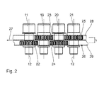
- the side view of Fig. 2 shows next to the turret 11 even more turrets 19 to 21 of these nozzles.
- more than four turrets are usually provided.
- up to 40 or more turrets can be used on a working width perpendicular to the drawing plane FIGS. 1 and 3 be provided between 800 mm and 1400 mm.
- the turrets 11 and 19 to 21 are all driven to rotate about mutually parallel axes of rotation, which are all designated in the drawing by the reference numeral 12.
- Two adjacent axes of rotation are arranged at a distance of 25 mm from each other.
- all rotary heads are arranged at the same distance from each other along the working width.
- a rotary drive for the turrets 11 and 19 to 21 has a drive train about pinion 22 to 25 of each rotary head 11, 19 to 21 running and designed as a belt 26 and metallic tooth chain endless traction member.
- the belt 26 is perpendicular to its path 27 and parallel to the plane of the Fig. 2 divided into two tensile sections 28, 29, wherein the tensile portion 28 of the input side of the rotary heads 11, 19 to 21 and the pulling portion 29 of the discharge side of the rotary heads 11, 19 to 21 faces.
- the drive pinion 22 to 25 adjacent rotary heads 11, 19 to 21 are offset in height by a distance h to each other. In a first turret group with the turrets 11 and 20 are therefore the drive pinion 22, 24 in Fig.
- the offset h corresponds to the distance between the two tensile sections 28, 29 of the belt 26 to each other.
- the pulling section 29 passes over the driving pinions 22, 24 of the rotary heads 11, 20 of the first turret group.
- the pulling section 28 passes over the drive pinions 23, 25 of the rotary heads 19, 21 of the second rotary head group. Therefore, the pulling portion 29 of the belt 26 for driving the first turret group and the second pulling portion 28 for driving the second turret group are formed.
- the two tension sections 28, 29 are arranged on an inner side of the belt 26. On the outside, the pull sections 28, 29 are supported by two slide rails 30, 31 against the nozzle carrier 15. The two tension sections 28, 29 are separated from each other by a guide web 32.
- the dough is squeezed out through the rotary nozzles 9.
- the rotary heads 11, 19 to 21, driven by the belt 26 and a motor, not shown, are rotated. This rotation causes the biscuit strand 10, which is pressed out of the nozzle opening 14, to be twisted after the rotary heads 11, 19 to 21 in the form of a helix.
- the latter is further transported by a driven endless conveyor belt 37 for baking.
- the plant for the production of biscuits still on a cooling and packaging device.
- the plant may also comprise a lye bath, a spreading unit with a spreading conveyor and a cutting unit with a cutting and oven transfer conveyor.
- All rotary nozzles 9 are in communication with the dough pressure chamber 7. Depending on the number of rotary nozzles 9, a corresponding number of pastry strands 10 can be pressed out at the same time with the pressing device 1 and conveyed on to the endless conveyor belt 37.
- Fig. 4 shows a front view of the pressing device 1 with a gear box 16 and the nozzle carrier 15.
- rotary nozzles 9 are provided rotatably drivable.
- Such a nozzle carrier 15 has a useful width of 1150 mm. It is also possible to equip the nozzle carrier 15 with 31 rotary nozzles 9, 39 rotary nozzles 9 or 55 rotary nozzles 9.
- the nozzle carrier 15 then has a useful width of 750 mm, 950 mm and 1350 mm respectively.
- the effective width of the nozzle carrier 15 results from the intermediate spaces arranged between the rotary nozzles 9 and the width of the intermediate spaces, which according to the exemplary embodiment shown constant at 25 mm. It is conceivable to provide other than the rotary nozzle numbers mentioned on a nozzle carrier 15.
- Fig. 5 shows the pressing device 1 according to Fig. 4 , wherein the nozzle carrier 15 is removed from the gear box 16.
- the gearbox 16 together with the nozzle carrier 15 of the pressing device 1, which is designed as embroidery press, to a parallel to the axis of rotation of the Riffelwalze 4 arranged pivot axis 52 pivots. It is not necessary to disassemble the gear box 16 from the nozzle carrier 15 to allow accessibility of the interchangeable inserts 36.
- the interchangeable inserts 36 can be replaced. This simplifies the accessibility of the interchangeable inserts.
- FIG. 6 shows the pressing device 1 with the pivotable about a pivot axis 52 pivotally mounted nozzle carrier 15, is mounted on the gear box 16.
- the nozzle carrier 15 is shown in a pivoted arrangement. In this arrangement, it is possible to remove the interchangeable inserts 36 from the gear box 16. Starting from this maintenance and exchange arrangement of the nozzle carrier 15, this can be pivoted along a pivoting direction 53 about the pivot axis 52 into a working arrangement. The pivoting movement takes place in the pivoting direction 53 with respect to the pivot axis by approximately 90 °.
- the nozzle carrier 15 is substantially vertical as shown in FIG Fig. 1 arranged.
- the dough pressure chamber 7 is then connected to the storage chamber 3.
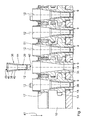
- Fig. 7 shows an enlarged sectional view of the gear box 16 with a plurality of rotatable about its respective axis of rotation 12 arranged rotary nozzles 9.
- an external toothing 51 adjacent rotary nozzles 9 is arranged offset.
- the staggered arrangement of the rotary nozzles 9 is carried out such that in each case the next but one rotary nozzle 9 is made identical.
- the staggered arrangement of the rotary nozzles 9 thus takes place alternately.
- Such an arrangement of the rotary nozzles 9 is compact and serves the drive for the tensile strand.
- the nozzles 9 have identical inner contours and have an exchange insert receptacle 35, which is arranged in the region of the nozzle opening 14 within the rotary nozzle 9.
- the exchange insert receptacle 35 has a conically executed inner contour.
- the exchange insert 36 is inserted along the axis of rotation 12.
- the exchange insert 36 has a fastening section 38 with a conical surface on an outer contour.
- the outer contour of the interchangeable insert 36 surrounds a dough guide channel 39 which connects a feed opening 40 along a dough guide direction 41 to a dispensing opening 42.
- the feed opening 40 serves to feed dough into the exchange insert 36.
- the discharge opening 42 serves to dispense the dough pressed by the exchange insert 36.
- the nozzle opening 14 and the discharge opening 42 are arranged adjacent to each other and in particular concentrically with the axis of rotation 12.
- the exchange insert 36 is designed substantially sleeve-shaped and can be inserted as a plug-in sleeve into the rotary nozzle 9.
- the interchangeable insert 36 Perpendicular to the axis of rotation 12, the interchangeable insert 36 has a substantially annular cross-sectional area, wherein the inner contour of the cross-sectional area, in particular in the area of the dispensing opening 42, is non-circular can be. In the region of the dispensing opening 42, the cross-sectional area of the interchangeable insert 36 is dependent on a product to be produced. Along the axis of rotation 12, the cross-sectional area may be variable, ie size and / or shape of outer and / or inner contour.
- the interchangeable insert 36 is securely held by the mounting portion 38 in the removable insert holder 35 of the rotary nozzle 9. Due to the conical surface of the attachment portion 38, the exchange insert 36 is axial, i. along the dough guide direction 41, securely held in the rotary nozzle 9. An axial slippage due to a pressing force is thereby prevented. In addition, the interchangeable insert 36 is secured against rotation about the axis of rotation 12 by the frictional force acting in the region of the fastening section 38 between the interchangeable insert 36 and the interchangeable insert holder 35 of the rotary nozzle 9. The interchangeable insert 36 has along the axis of rotation 12 a substantially constant wall thickness of a wall 44.
- the discharge opening 42 has a cross section oriented perpendicular to the axis of rotation 12, which is reduced in relation to a corresponding cross section of the supply opening 40 oriented perpendicular to the axis of rotation 12. Accordingly, a dough pressed by the exchange insert 36 is compressed along the dough-carrying direction 41.
- the dough guide channel 39 is oriented substantially parallel to the axis of rotation 12 and has a compression section 43. In the compression section 43, a cross section of the dough guide channel 39 oriented perpendicular to the axis of rotation 12 is reduced along the dough guide direction 41.
- the exchange insert according to the embodiment shown in the Fig. 7 and 8th has exactly one discharge opening 42. It is also possible that the interchangeable insert 36 has a plurality of dispensing openings 42 in the case of a biscuit strand to be designed correspondingly. In this case, the discharge openings 42 may be arranged concentrically or in another manner with respect to the axis of rotation 12. With multiple dispensing openings, it is possible to make a pastry strand in the form of a multiple helix.
- the feed opening 40 is circular and has an insertion bevel 45.
- the interchangeable insert 36 has a rectangular cross-section oriented perpendicular to the axis of rotation 12.
- the interchangeable insert 36 is made of polytetrafluoroethylene (PTFE), also known under the trade name Teflon. It is also possible to manufacture the interchangeable insert 36 from metal and in particular from stainless steel or other plastics.
- the rotary nozzle 9 is made of stainless steel.
- the rectangular cross-section of the discharge opening 42 is in Fig. 8 shown.
- the rectangular cross section has a ratio of length to width of about 2: 1.
- the ratio can also be greater or less than 2: 1. It is also possible to make the cross section of the discharge opening 42 triangular, pentagonal or in the form of another polygon.
- Fig. 9 shows a further embodiment of the interchangeable insert 36.
- Components that correspond to those already described above with reference to the Fig. 1 to 8 have the same reference numbers and will not be discussed again in detail.
- the cross section of the discharge opening 46 of the exchange insert 36 has a waisted rectangular shape. That is, the discharge port 46 is shaped substantially rectangular, similar to the discharge port 42 of the first embodiment. At the longer, according to Fig. 8 Above and below shown side lines of the discharge opening 46, a radius is provided such that the discharge opening 46 is made concave.
- the discharge opening 46 has a reduced width in a middle region of the longer side lines. In particular, the width of the discharge opening 46 on the axis of rotation 12 is minimal.
- the circular arc sections formed by the radii are arranged opposite to each other.
- the discharge opening 46 is made double symmetrical.
- Fig. 10 shows a further embodiment of a removable insert 36.
- Components that correspond to those already described above with reference to the Fig. 1 to 9 have the same reference numbers and will not be discussed again in detail.
- the exchange insert 36 has a discharge opening 47.
- the discharge opening 47 comprises three at least partially overlapping bores 48, which are arranged parallel to the axis of rotation 12.
- Each of the holes 48 has a diameter of 3 mm.
- the holes 48 are arranged on a circle of holes with the diameter of 3.3 mm at an angular distance of 120 ° with respect to the axis of rotation 12, i. the centers of the holes 48 are arranged on the pitch circle about the rotation axis 12 equidistant. It is also possible to carry out the discharge opening 47 with several or fewer than three bores 48. Accordingly, the diameter of the bolt circle or the diameter of the holes 48 can be varied.
- Fig. 11 shows a further embodiment of the interchangeable insert 36.
- Components that correspond to those already described above with reference to the Fig. 1 to 10 have the same reference numbers and will not be discussed again in detail.
- An exchange insert 36 has a discharge opening 50, which is designed as a circular bore concentric with the axis of rotation 12. Such a discharge opening 50 is uncomplicated and quickly produced.
Landscapes
- Life Sciences & Earth Sciences (AREA)
- Engineering & Computer Science (AREA)
- Food Science & Technology (AREA)
- Manufacturing And Processing Devices For Dough (AREA)
Priority Applications (2)
| Application Number | Priority Date | Filing Date | Title |
|---|---|---|---|
| PL12150860T PL2486798T3 (pl) | 2011-02-09 | 2012-01-12 | Wkładka wymienna do dyszy obrotowej |
| RS20181040A RS57652B1 (sr) | 2011-02-09 | 2012-01-12 | Izmenljivi umetak za rotacionu mlaznicu |
Applications Claiming Priority (1)
| Application Number | Priority Date | Filing Date | Title |
|---|---|---|---|
| DE102011003878A DE102011003878A1 (de) | 2011-02-09 | 2011-02-09 | Wechseleinsatz für eine Drehdüse |
Publications (3)
| Publication Number | Publication Date |
|---|---|
| EP2486798A2 true EP2486798A2 (fr) | 2012-08-15 |
| EP2486798A3 EP2486798A3 (fr) | 2015-12-23 |
| EP2486798B1 EP2486798B1 (fr) | 2018-07-04 |
Family
ID=45531192
Family Applications (1)
| Application Number | Title | Priority Date | Filing Date |
|---|---|---|---|
| EP12150860.0A Active EP2486798B1 (fr) | 2011-02-09 | 2012-01-12 | Pièce d'insertion interchangeable pour une buse rotative |
Country Status (4)
| Country | Link |
|---|---|
| EP (1) | EP2486798B1 (fr) |
| DE (2) | DE102011003878A1 (fr) |
| PL (1) | PL2486798T3 (fr) |
| RS (1) | RS57652B1 (fr) |
Cited By (2)
| Publication number | Priority date | Publication date | Assignee | Title |
|---|---|---|---|---|
| ITBO20130656A1 (it) * | 2013-11-28 | 2015-05-29 | Emanuel Rizzo | Trafila per l'estrusione di pasta alimentare |
| JP2017528307A (ja) * | 2014-07-16 | 2017-09-28 | エイメック フォスター ウィーラー エナージア オサケ ユキチュア | グリッド・ノズル組立体、グリッド・ノズル組立体を含む流動層反応器、及びグリッド・ノズル組立体を使用する方法 |
Citations (1)
| Publication number | Priority date | Publication date | Assignee | Title |
|---|---|---|---|---|
| EP1779732A2 (fr) | 2005-10-29 | 2007-05-02 | Werner & Pfleiderer Industrielle Backtechnik GmbH | Dispositif de pressage pour une installation de fabrication de barres de pâte |
Family Cites Families (7)
| Publication number | Priority date | Publication date | Assignee | Title |
|---|---|---|---|---|
| DE3400897C2 (de) * | 1984-01-12 | 1987-03-26 | Artur 7060 Schorndorf Föhl | Teigpresse |
| DK0704158T3 (da) * | 1994-09-29 | 2001-09-24 | Nestle Sa | Ekstruderhoved |
| RU2164747C2 (ru) * | 1998-06-22 | 2001-04-10 | Закрытое акционерное общество Научно-производственная фирма "ТЕКО" | Матрица прессующей головки машины для производства макаронных изделий |
| DE69917745T2 (de) * | 1999-03-17 | 2005-08-18 | Barilla G.E R. Fratelli S.P.A. | Verfahren zur Herstellung von Keksen in hauptsächlich geflochtener Form |
| US6450796B1 (en) * | 1999-07-13 | 2002-09-17 | Reading Bakery Systems | Rotating nozzle die machine for dough extrusion |
| DE19936829C2 (de) * | 1999-08-05 | 2003-02-27 | Hosokawa Bepex Gmbh | Düsenanordnung, Düsenträger und Vorrichtung zum Extrudieren teigiger Massen |
| KR20100101770A (ko) * | 2009-03-10 | 2010-09-20 | 최문영 | 가래떡 제조장치 |
-
2011
- 2011-02-09 DE DE102011003878A patent/DE102011003878A1/de not_active Ceased
-
2012
- 2012-01-12 RS RS20181040A patent/RS57652B1/sr unknown
- 2012-01-12 DE DE202012013318.7U patent/DE202012013318U1/de not_active Expired - Lifetime
- 2012-01-12 PL PL12150860T patent/PL2486798T3/pl unknown
- 2012-01-12 EP EP12150860.0A patent/EP2486798B1/fr active Active
Patent Citations (1)
| Publication number | Priority date | Publication date | Assignee | Title |
|---|---|---|---|---|
| EP1779732A2 (fr) | 2005-10-29 | 2007-05-02 | Werner & Pfleiderer Industrielle Backtechnik GmbH | Dispositif de pressage pour une installation de fabrication de barres de pâte |
Cited By (2)
| Publication number | Priority date | Publication date | Assignee | Title |
|---|---|---|---|---|
| ITBO20130656A1 (it) * | 2013-11-28 | 2015-05-29 | Emanuel Rizzo | Trafila per l'estrusione di pasta alimentare |
| JP2017528307A (ja) * | 2014-07-16 | 2017-09-28 | エイメック フォスター ウィーラー エナージア オサケ ユキチュア | グリッド・ノズル組立体、グリッド・ノズル組立体を含む流動層反応器、及びグリッド・ノズル組立体を使用する方法 |
Also Published As
| Publication number | Publication date |
|---|---|
| PL2486798T3 (pl) | 2019-01-31 |
| DE102011003878A1 (de) | 2012-08-09 |
| EP2486798B1 (fr) | 2018-07-04 |
| DE202012013318U1 (de) | 2016-03-11 |
| EP2486798A3 (fr) | 2015-12-23 |
| RS57652B1 (sr) | 2018-11-30 |
Similar Documents
| Publication | Publication Date | Title |
|---|---|---|
| EP1905308A2 (fr) | Dispositif de fabrication d'une bande de pâte à partir d'une bande de pâte crue tout comme ensemble de laminoir planétaire à utiliser dans un tel dispositif | |
| EP3247214B1 (fr) | Machine de traitement de pâtes, procédé de fabrication de pâtes avec une telle machine de traitement de pâtes et son utilisation et composite d'ébauche de pâtes | |
| EP2163375B1 (fr) | Dispositif destiné à presser des récipients déformables vides | |
| WO2001010227A1 (fr) | Ensemble filiere, porte-filiere et dispositif pour extruder des matieres sous forme de pate | |
| DE19936815C2 (de) | Düsenanordnung, Düsenträger und Vorrichtung zum Extrudieren teigiger Massen | |
| EP3849318B1 (fr) | Dispositif de formation d'une bande de pâte avec dispositif de coupe | |
| EP2486798B1 (fr) | Pièce d'insertion interchangeable pour une buse rotative | |
| EP2830432B1 (fr) | Dispositf pour le dosage et l'extraction des masses visqueuses | |
| EP2106707B1 (fr) | Dispositif de transport et de support dans la direction de transport T d'articles en forme de tronçons alimentés en continu, procédé d'adaptation d'un tel dispositif aux différentes longueurs de coupe ainsi qu'essieu tubulaire | |
| DE4424461B4 (de) | Vorrichtung zum Extrudieren von essbarem Teig | |
| WO2001008497A1 (fr) | Dispositif pour former une bande de pate | |
| EP2514328B1 (fr) | Dispositif destiné à extruder des masses d'aliments | |
| DE4307937C2 (de) | Teigteil-Wirkmaschine | |
| DE202009001697U1 (de) | Vorrichtung zum Pressen von Pellets | |
| EP3417711B1 (fr) | Dispositif de preparation de pate | |
| WO2003022057A2 (fr) | Diviseuse pour pate | |
| DE2850936C3 (de) | Maschine zum Rundwirken von Teig | |
| EP1779732B1 (fr) | Dispositif de pressage pour une installation de fabrication de barres de pâte | |
| DE19917390C2 (de) | Vorrichtung zum Bearbeiten eines Teigstrangs | |
| DE112017005288B4 (de) | Wickelvorrichtung und backmaschine | |
| AT520460B1 (de) | Vorrichtung zum Formen eines Teigbandes | |
| AT13119U1 (de) | Portioniereinheit für Teigteilmaschinen | |
| DE602004004161T2 (de) | Vorrichtung zum Ablegen von essbarer Masse. | |
| EP1747725B1 (fr) | Dispositif de pressage pour une installation de fabrication de produits de pâtisserie en forme de barre | |
| DE3516098A1 (de) | Vorrichtung zum ausformen von brezeln |
Legal Events
| Date | Code | Title | Description |
|---|---|---|---|
| REG | Reference to a national code |
Ref country code: DE Ref legal event code: R138 Ref document number: 202012013318 Country of ref document: DE Free format text: GERMAN DOCUMENT NUMBER IS 502012012964 |
|
| PUAI | Public reference made under article 153(3) epc to a published international application that has entered the european phase |
Free format text: ORIGINAL CODE: 0009012 |
|
| AK | Designated contracting states |
Kind code of ref document: A2 Designated state(s): AL AT BE BG CH CY CZ DE DK EE ES FI FR GB GR HR HU IE IS IT LI LT LU LV MC MK MT NL NO PL PT RO RS SE SI SK SM TR |
|
| AX | Request for extension of the european patent |
Extension state: BA ME |
|
| PUAL | Search report despatched |
Free format text: ORIGINAL CODE: 0009013 |
|
| AK | Designated contracting states |
Kind code of ref document: A3 Designated state(s): AL AT BE BG CH CY CZ DE DK EE ES FI FR GB GR HR HU IE IS IT LI LT LU LV MC MK MT NL NO PL PT RO RS SE SI SK SM TR |
|
| AX | Request for extension of the european patent |
Extension state: BA ME |
|
| RIC1 | Information provided on ipc code assigned before grant |
Ipc: A21C 11/16 20060101AFI20151118BHEP |
|
| 17P | Request for examination filed |
Effective date: 20160610 |
|
| RBV | Designated contracting states (corrected) |
Designated state(s): AL AT BE BG CH CY CZ DE DK EE ES FI FR GB GR HR HU IE IS IT LI LT LU LV MC MK MT NL NO PL PT RO RS SE SI SK SM TR |
|
| 17Q | First examination report despatched |
Effective date: 20161017 |
|
| STAA | Information on the status of an ep patent application or granted ep patent |
Free format text: STATUS: EXAMINATION IS IN PROGRESS |
|
| GRAP | Despatch of communication of intention to grant a patent |
Free format text: ORIGINAL CODE: EPIDOSNIGR1 |
|
| STAA | Information on the status of an ep patent application or granted ep patent |
Free format text: STATUS: GRANT OF PATENT IS INTENDED |
|
| GRAJ | Information related to disapproval of communication of intention to grant by the applicant or resumption of examination proceedings by the epo deleted |
Free format text: ORIGINAL CODE: EPIDOSDIGR1 |
|
| STAA | Information on the status of an ep patent application or granted ep patent |
Free format text: STATUS: EXAMINATION IS IN PROGRESS |
|
| INTG | Intention to grant announced |
Effective date: 20171030 |
|
| GRAP | Despatch of communication of intention to grant a patent |
Free format text: ORIGINAL CODE: EPIDOSNIGR1 |
|
| STAA | Information on the status of an ep patent application or granted ep patent |
Free format text: STATUS: GRANT OF PATENT IS INTENDED |
|
| INTC | Intention to grant announced (deleted) | ||
| INTG | Intention to grant announced |
Effective date: 20171206 |
|
| GRAS | Grant fee paid |
Free format text: ORIGINAL CODE: EPIDOSNIGR3 |
|
| GRAA | (expected) grant |
Free format text: ORIGINAL CODE: 0009210 |
|
| STAA | Information on the status of an ep patent application or granted ep patent |
Free format text: STATUS: THE PATENT HAS BEEN GRANTED |
|
| AK | Designated contracting states |
Kind code of ref document: B1 Designated state(s): AL AT BE BG CH CY CZ DE DK EE ES FI FR GB GR HR HU IE IS IT LI LT LU LV MC MK MT NL NO PL PT RO RS SE SI SK SM TR |
|
| REG | Reference to a national code |
Ref country code: GB Ref legal event code: FG4D Free format text: NOT ENGLISH |
|
| REG | Reference to a national code |
Ref country code: CH Ref legal event code: EP |
|
| REG | Reference to a national code |
Ref country code: AT Ref legal event code: REF Ref document number: 1013531 Country of ref document: AT Kind code of ref document: T Effective date: 20180715 |
|
| REG | Reference to a national code |
Ref country code: IE Ref legal event code: FG4D Free format text: LANGUAGE OF EP DOCUMENT: GERMAN |
|
| REG | Reference to a national code |
Ref country code: DE Ref legal event code: R096 Ref document number: 502012012964 Country of ref document: DE |
|
| REG | Reference to a national code |
Ref country code: RO Ref legal event code: EPE |
|
| REG | Reference to a national code |
Ref country code: NL Ref legal event code: MP Effective date: 20180704 |
|
| REG | Reference to a national code |
Ref country code: LT Ref legal event code: MG4D |
|
| PG25 | Lapsed in a contracting state [announced via postgrant information from national office to epo] |
Ref country code: NL Free format text: LAPSE BECAUSE OF FAILURE TO SUBMIT A TRANSLATION OF THE DESCRIPTION OR TO PAY THE FEE WITHIN THE PRESCRIBED TIME-LIMIT Effective date: 20180704 |
|
| PG25 | Lapsed in a contracting state [announced via postgrant information from national office to epo] |
Ref country code: BG Free format text: LAPSE BECAUSE OF FAILURE TO SUBMIT A TRANSLATION OF THE DESCRIPTION OR TO PAY THE FEE WITHIN THE PRESCRIBED TIME-LIMIT Effective date: 20181004 Ref country code: SE Free format text: LAPSE BECAUSE OF FAILURE TO SUBMIT A TRANSLATION OF THE DESCRIPTION OR TO PAY THE FEE WITHIN THE PRESCRIBED TIME-LIMIT Effective date: 20180704 Ref country code: GR Free format text: LAPSE BECAUSE OF FAILURE TO SUBMIT A TRANSLATION OF THE DESCRIPTION OR TO PAY THE FEE WITHIN THE PRESCRIBED TIME-LIMIT Effective date: 20181005 Ref country code: LT Free format text: LAPSE BECAUSE OF FAILURE TO SUBMIT A TRANSLATION OF THE DESCRIPTION OR TO PAY THE FEE WITHIN THE PRESCRIBED TIME-LIMIT Effective date: 20180704 Ref country code: CZ Free format text: LAPSE BECAUSE OF FAILURE TO SUBMIT A TRANSLATION OF THE DESCRIPTION OR TO PAY THE FEE WITHIN THE PRESCRIBED TIME-LIMIT Effective date: 20180704 Ref country code: FI Free format text: LAPSE BECAUSE OF FAILURE TO SUBMIT A TRANSLATION OF THE DESCRIPTION OR TO PAY THE FEE WITHIN THE PRESCRIBED TIME-LIMIT Effective date: 20180704 Ref country code: NO Free format text: LAPSE BECAUSE OF FAILURE TO SUBMIT A TRANSLATION OF THE DESCRIPTION OR TO PAY THE FEE WITHIN THE PRESCRIBED TIME-LIMIT Effective date: 20181004 Ref country code: IS Free format text: LAPSE BECAUSE OF FAILURE TO SUBMIT A TRANSLATION OF THE DESCRIPTION OR TO PAY THE FEE WITHIN THE PRESCRIBED TIME-LIMIT Effective date: 20181104 |
|
| PG25 | Lapsed in a contracting state [announced via postgrant information from national office to epo] |
Ref country code: LV Free format text: LAPSE BECAUSE OF FAILURE TO SUBMIT A TRANSLATION OF THE DESCRIPTION OR TO PAY THE FEE WITHIN THE PRESCRIBED TIME-LIMIT Effective date: 20180704 Ref country code: HR Free format text: LAPSE BECAUSE OF FAILURE TO SUBMIT A TRANSLATION OF THE DESCRIPTION OR TO PAY THE FEE WITHIN THE PRESCRIBED TIME-LIMIT Effective date: 20180704 Ref country code: ES Free format text: LAPSE BECAUSE OF FAILURE TO SUBMIT A TRANSLATION OF THE DESCRIPTION OR TO PAY THE FEE WITHIN THE PRESCRIBED TIME-LIMIT Effective date: 20180704 Ref country code: AL Free format text: LAPSE BECAUSE OF FAILURE TO SUBMIT A TRANSLATION OF THE DESCRIPTION OR TO PAY THE FEE WITHIN THE PRESCRIBED TIME-LIMIT Effective date: 20180704 |
|
| REG | Reference to a national code |
Ref country code: DE Ref legal event code: R097 Ref document number: 502012012964 Country of ref document: DE |
|
| PG25 | Lapsed in a contracting state [announced via postgrant information from national office to epo] |
Ref country code: EE Free format text: LAPSE BECAUSE OF FAILURE TO SUBMIT A TRANSLATION OF THE DESCRIPTION OR TO PAY THE FEE WITHIN THE PRESCRIBED TIME-LIMIT Effective date: 20180704 |
|
| PLBE | No opposition filed within time limit |
Free format text: ORIGINAL CODE: 0009261 |
|
| STAA | Information on the status of an ep patent application or granted ep patent |
Free format text: STATUS: NO OPPOSITION FILED WITHIN TIME LIMIT |
|
| PG25 | Lapsed in a contracting state [announced via postgrant information from national office to epo] |
Ref country code: SK Free format text: LAPSE BECAUSE OF FAILURE TO SUBMIT A TRANSLATION OF THE DESCRIPTION OR TO PAY THE FEE WITHIN THE PRESCRIBED TIME-LIMIT Effective date: 20180704 Ref country code: DK Free format text: LAPSE BECAUSE OF FAILURE TO SUBMIT A TRANSLATION OF THE DESCRIPTION OR TO PAY THE FEE WITHIN THE PRESCRIBED TIME-LIMIT Effective date: 20180704 Ref country code: SM Free format text: LAPSE BECAUSE OF FAILURE TO SUBMIT A TRANSLATION OF THE DESCRIPTION OR TO PAY THE FEE WITHIN THE PRESCRIBED TIME-LIMIT Effective date: 20180704 |
|
| 26N | No opposition filed |
Effective date: 20190405 |
|
| PG25 | Lapsed in a contracting state [announced via postgrant information from national office to epo] |
Ref country code: SI Free format text: LAPSE BECAUSE OF FAILURE TO SUBMIT A TRANSLATION OF THE DESCRIPTION OR TO PAY THE FEE WITHIN THE PRESCRIBED TIME-LIMIT Effective date: 20180704 Ref country code: MC Free format text: LAPSE BECAUSE OF FAILURE TO SUBMIT A TRANSLATION OF THE DESCRIPTION OR TO PAY THE FEE WITHIN THE PRESCRIBED TIME-LIMIT Effective date: 20180704 |
|
| REG | Reference to a national code |
Ref country code: CH Ref legal event code: PL |
|
| GBPC | Gb: european patent ceased through non-payment of renewal fee |
Effective date: 20190112 |
|
| PG25 | Lapsed in a contracting state [announced via postgrant information from national office to epo] |
Ref country code: LU Free format text: LAPSE BECAUSE OF NON-PAYMENT OF DUE FEES Effective date: 20190112 |
|
| REG | Reference to a national code |
Ref country code: BE Ref legal event code: MM Effective date: 20190131 |
|
| REG | Reference to a national code |
Ref country code: IE Ref legal event code: MM4A |
|
| PG25 | Lapsed in a contracting state [announced via postgrant information from national office to epo] |
Ref country code: BE Free format text: LAPSE BECAUSE OF NON-PAYMENT OF DUE FEES Effective date: 20190131 |
|
| PG25 | Lapsed in a contracting state [announced via postgrant information from national office to epo] |
Ref country code: LI Free format text: LAPSE BECAUSE OF NON-PAYMENT OF DUE FEES Effective date: 20190131 Ref country code: GB Free format text: LAPSE BECAUSE OF NON-PAYMENT OF DUE FEES Effective date: 20190112 Ref country code: CH Free format text: LAPSE BECAUSE OF NON-PAYMENT OF DUE FEES Effective date: 20190131 |
|
| PG25 | Lapsed in a contracting state [announced via postgrant information from national office to epo] |
Ref country code: IE Free format text: LAPSE BECAUSE OF NON-PAYMENT OF DUE FEES Effective date: 20190112 |
|
| PG25 | Lapsed in a contracting state [announced via postgrant information from national office to epo] |
Ref country code: TR Free format text: LAPSE BECAUSE OF FAILURE TO SUBMIT A TRANSLATION OF THE DESCRIPTION OR TO PAY THE FEE WITHIN THE PRESCRIBED TIME-LIMIT Effective date: 20180704 |
|
| PG25 | Lapsed in a contracting state [announced via postgrant information from national office to epo] |
Ref country code: MT Free format text: LAPSE BECAUSE OF FAILURE TO SUBMIT A TRANSLATION OF THE DESCRIPTION OR TO PAY THE FEE WITHIN THE PRESCRIBED TIME-LIMIT Effective date: 20180704 Ref country code: PT Free format text: LAPSE BECAUSE OF FAILURE TO SUBMIT A TRANSLATION OF THE DESCRIPTION OR TO PAY THE FEE WITHIN THE PRESCRIBED TIME-LIMIT Effective date: 20181105 |
|
| PG25 | Lapsed in a contracting state [announced via postgrant information from national office to epo] |
Ref country code: CY Free format text: LAPSE BECAUSE OF FAILURE TO SUBMIT A TRANSLATION OF THE DESCRIPTION OR TO PAY THE FEE WITHIN THE PRESCRIBED TIME-LIMIT Effective date: 20180704 |
|
| PG25 | Lapsed in a contracting state [announced via postgrant information from national office to epo] |
Ref country code: HU Free format text: LAPSE BECAUSE OF FAILURE TO SUBMIT A TRANSLATION OF THE DESCRIPTION OR TO PAY THE FEE WITHIN THE PRESCRIBED TIME-LIMIT; INVALID AB INITIO Effective date: 20120112 |
|
| PG25 | Lapsed in a contracting state [announced via postgrant information from national office to epo] |
Ref country code: MK Free format text: LAPSE BECAUSE OF FAILURE TO SUBMIT A TRANSLATION OF THE DESCRIPTION OR TO PAY THE FEE WITHIN THE PRESCRIBED TIME-LIMIT Effective date: 20180704 |
|
| PGFP | Annual fee paid to national office [announced via postgrant information from national office to epo] |
Ref country code: RS Payment date: 20251230 Year of fee payment: 15 |
|
| PGFP | Annual fee paid to national office [announced via postgrant information from national office to epo] |
Ref country code: DE Payment date: 20260324 Year of fee payment: 15 |
|
| PGFP | Annual fee paid to national office [announced via postgrant information from national office to epo] |
Ref country code: AT Payment date: 20260107 Year of fee payment: 15 |
|
| PGFP | Annual fee paid to national office [announced via postgrant information from national office to epo] |
Ref country code: RO Payment date: 20260112 Year of fee payment: 15 Ref country code: IT Payment date: 20260130 Year of fee payment: 15 |
|
| PGFP | Annual fee paid to national office [announced via postgrant information from national office to epo] |
Ref country code: FR Payment date: 20260123 Year of fee payment: 15 |
|
| PGFP | Annual fee paid to national office [announced via postgrant information from national office to epo] |
Ref country code: PL Payment date: 20260109 Year of fee payment: 15 |