EP2487324A2 - Procédé de démontage d'un segment de tige de forage d'une tige de forage d'une machine de forage et machine de forage - Google Patents
Procédé de démontage d'un segment de tige de forage d'une tige de forage d'une machine de forage et machine de forage Download PDFInfo
- Publication number
- EP2487324A2 EP2487324A2 EP20120154728 EP12154728A EP2487324A2 EP 2487324 A2 EP2487324 A2 EP 2487324A2 EP 20120154728 EP20120154728 EP 20120154728 EP 12154728 A EP12154728 A EP 12154728A EP 2487324 A2 EP2487324 A2 EP 2487324A2
- Authority
- EP
- European Patent Office
- Prior art keywords
- key
- drill string
- raise
- boring machine
- rotary drive
- Prior art date
- Legal status (The legal status is an assumption and is not a legal conclusion. Google has not performed a legal analysis and makes no representation as to the accuracy of the status listed.)
- Withdrawn
Links
- 238000000034 method Methods 0.000 title claims abstract description 16
- 238000005553 drilling Methods 0.000 title description 9
- 230000005693 optoelectronics Effects 0.000 claims description 2
- 230000001939 inductive effect Effects 0.000 claims 1
- 238000003754 machining Methods 0.000 claims 1
- 230000005540 biological transmission Effects 0.000 description 4
- 240000006829 Ficus sundaica Species 0.000 description 2
- 208000012886 Vertigo Diseases 0.000 description 2
- 238000013461 design Methods 0.000 description 2
- 238000006073 displacement reaction Methods 0.000 description 2
- 241001295925 Gegenes Species 0.000 description 1
- 208000027418 Wounds and injury Diseases 0.000 description 1
- 238000010521 absorption reaction Methods 0.000 description 1
- 238000013459 approach Methods 0.000 description 1
- 230000000295 complement effect Effects 0.000 description 1
- 230000006378 damage Effects 0.000 description 1
- 238000001514 detection method Methods 0.000 description 1
- 238000011161 development Methods 0.000 description 1
- 230000000694 effects Effects 0.000 description 1
- 208000014674 injury Diseases 0.000 description 1
- 238000003780 insertion Methods 0.000 description 1
- 230000037431 insertion Effects 0.000 description 1
- 238000004519 manufacturing process Methods 0.000 description 1
Images



Classifications
-
- E—FIXED CONSTRUCTIONS
- E21—EARTH OR ROCK DRILLING; MINING
- E21B—EARTH OR ROCK DRILLING; OBTAINING OIL, GAS, WATER, SOLUBLE OR MELTABLE MATERIALS OR A SLURRY OF MINERALS FROM WELLS
- E21B19/00—Handling rods, casings, tubes or the like outside the borehole, e.g. in the derrick; Apparatus for feeding the rods or cables
- E21B19/16—Connecting or disconnecting pipe couplings or joints
- E21B19/167—Connecting or disconnecting pipe couplings or joints using a wrench adapted to engage a non circular section of pipe, e.g. a section with flats or splines
Definitions
- the invention relates to a method for removing a BohrgestCodesegments a drill string Raise-Boring machine, in which the screw connection of each of an upper first BohrgestCodesegments whose upper end is screwed to a rotary drive device, is released from a subsequent below, second BohrgestShesegment.
- the invention also relates to a raise-boring machine.
- up-drilling is a drilling process in which a circular well can be made between a subterranean cavity and a higher level, drilling downhole from a pilot hole. This method is used in particular for the production of connections between two routes in a mine or between a cavern and the earth's surface.
- an extension tool is mounted at the base of the bore on a drill pipe comprising a plurality of drill string segments bolted together. To extend the pilot hole, the drill pipe is rotated and caught up. Each time a drill string segment length is drilled, a drill string segment must be removed.
- the drill string below the segment to be removed intercepted, for which an interceptor is provided. It includes a interceptor key engageable with a key surface provided in the upper portion of a second drill string segment following the first upper tubular segment to be excavated down.
- the interceptor key is often manually pushed onto the key area. Since this process occurs in the work space of the raise boring machine, i. within the space bounded by the machine frame, it is associated with a high accident risk. This is especially true when the Raise Boring device is used to expand a perpendicular to the inclined pilot hole, as an attached interceptor in the case of mounting positions in which its prongs obliquely upward, tends to unwanted dropping.
- a raise-boring machine is known in which the first drill pipe segment to be removed is countered with an intercepting wedge before the screw connection between the rotary drive device and this drill pipe segment is loosened or loosened. After the upward drilling has progressed so far that the uppermost BohrgestShesegment can be removed, this must therefore be lowered for countering.
- the invention is therefore based on the object, with respect to the risk of injury improved method for expanding a BohrgestShesegments a drill string Raise Boring machine, as well as a Raise Boring machine to perform the method.
- the raise-boring machine according to the invention which is suitable for carrying out the method according to the invention, comprises a drill pipe comprising drill string segments which can be screwed together, wherein each drill string segment comprises at least one spanner surface at its upper area in operating position, as well as a rotary drive device for rotary drive which can be raised and lowered the drill string to which the drill string is bolted.
- the rotary drive device includes a rotary encoder that communicates with a controller for the rotary drive device such that rotation of the drill string can be stopped in rotational angular positions in which the at least one key surface is in an angular position suitable for mechanical attachment of a interceptor key after the preparation of the refractive key for loosening drill pipe segments screwed together, a rotation into a rotational angle position takes place, which enables a mechanical removal of the refractive key.
- the rotary drive device preferably comprises a reduction gear.
- the Drehwinkelaufillon preferably cooperates with the transmission main shaft, with which the upper end of the first BohrgestShesegments is connected for operation.
- the Drehwinkelaufillon is connected to a programmable logic controller for the rotary drive device. It is then possible to program the programmable logic controller for various drill string embodiments and applications, so that a correct angular position of the key surfaces for applying the intercept or break key is always ensured without the intervention of operating personnel.
- a further preferred embodiment of the Raise-Boring machine comprises a capture receptacle, in which the interceptor key can be introduced, and a crushing receptacle, in which the crushing bowl can be introduced.
- a capture receptacle in which the interceptor key can be introduced
- a crushing receptacle in which the crushing bowl can be introduced.
- means for Wheelarret ist between an interceptor in the interceptor interceptor and / or located in the Breching Breching key are provided, wherein the means on the interceptor key and / or the crusher provided toothing, which engages in a provided on the interceptor or the Brech method counter teeth. Due to this measure, the rotational locking is effected automatically as soon as the interceptor key is in the interception receptacle or the breaking key is in the crushing receptacle.
- the mechanical introduction of the interceptor key in the interceptor or the Brech negotiatels in the crushing receptacle, the teeth and the counter teeth are formed such that there is a backlash
- this can not be formed in the teeth and / or in the counter teeth every second tooth.
- the raise boring machine according to the invention also comprises means with which the positions of the key faces suitable for the mechanical attachment of the interceptor key or breaker key can be detected, then depending on the size and structural design of the riser Boring machine for operators difficult action to shift by manual control of the rotary actuator, the wrench flats in the required positions.
- each drill string comprises at least four in a plane perpendicular to the longitudinal extension arranged key surfaces.
- this design is suitable for the approach of clamp-like trained interception and breaking keys, on the other hand can be transmitted over four key surfaces the considerable, necessary to release the screw connections of two BohrgestShesegmente torques and high interception forces in long drill pipes without deformation of the key surfaces.
- To further increase the transmissible moments and forces and other key surfaces can be provided in one or more, further levels, in which then adapted or other keys can be brought into engagement.
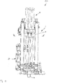
- the designated in the drawing as a whole with 100 Raise Boring machine (hereinafter also just “machine”) comprises a machine frame 1, on which a rotary drive means 2 by means of hydraulically actuated piston / cylinder units 3 in the longitudinal direction of a drill string 4 is displaceably guided.
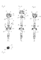
- the drill string 4 comprises a plurality of drill string segments, of which in Fig. 4 only the upper, first BohrgestCodesegment 5, a second, adjoining the first BohrgestCodesegment 5 below BohrgestTempesegment 6 and another, adjoining the second BohrgestShesegment 6 BohrgestHaresegment 7 are shown.
- the raise-boring machine 100 is used to extend a pilot hole from bottom to top, for which purpose on the not visible in the drawing, lower end of the drill string 4 an extension tool, such as a Bohrlochtechnikr is mounted in a known manner.
- the rotary drive device 2 which comprises a flanged gear 8 with a main shaft 9 with a threaded receptacle 10, is screwed onto a complementary external thread 11 of the upper end of that drill string segment 5, 6, 7, which is held by an interceptor 12 (s. Fig. 10 ).
- the first BohrgestShesegment 5 comprises at its lower end a threaded receptacle 14, which corresponds approximately to the threaded receptacle 10 on the main shaft 9, the upper end 13 of the second BohrgestShesegments 6 an external thread 15, which the external thread 11 corresponds.
- the first drill string segment 5 In order to be able to continue driving the bore upward, the first drill string segment 5 must be removed and the rotary drive device 2 then screwed to the upper end 13 of the second drill pipe segment 6.
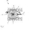
- a catch receptacle 21 is provided on the machine frame 1 of the raise boring machine 100, which surrounds the drill pipe 4 approximately concentrically. It serves to receive a interception key 17, which is designed like a clamp and can be placed around the drill string (see in particular FIG Fig. 4 ).
- the interception key comprises four key surfaces 18, which are arranged in the closed state of the interceptor key 17 at an angle of 90 ° to each other.
- key surfaces 19 are incorporated into the outer circumference in two spaced-apart planes perpendicular to the longitudinal axis L of the drill pipe 4, on which plane the key surfaces 18 lie flat with the interception key closed.
- the closed state of the interceptor is therefore rotatably and non-positively connected in the direction of the longitudinal axis L form-fitting manner with the drill pipe 4.
- interception key 17 For automatic attachment and removal of the interception key 17 is a purely in Fig. 2 It is designed such that the interception key 17 between a in Fig. 2 shown, outer position and the drill string 4 enclosing position is approximately perpendicular to the longitudinal axis L displaced and the interception key 17 can be opened and closed. He is not with the handling device 20 firmly connected, so that these after putting it on the drill pipe in the in Fig. 2 shown position outside the working space is displaced back.
- the interceptor key 17 After attaching and closing the interceptor key 17 with the aid of the handling device 20, the interceptor key 17 completely surrounds the drill pipe 4 and its key surfaces 19 co-operate flatly with the flats 18 of the segment 6 of the drill string 4, as shown in FIG Fig. 6 is shown, the handling device 20 is moved back and the drill pipe 4 in his in Fig. 5 shifted position shown. In this rests the interceptor key 17 in a rotatably disposed within the machine frame interceptor 21st
- the interceptor key 17 comprises on its outer surface a spur toothing 22 which engages in an internal toothing 23 of the catch receptacle 21, as in FIG Fig. 11 is shown.
- the spur gear teeth 22 and the internal teeth 23 are formed such that the interceptor key 17 in the interceptor 21 has a backlash of about twice the tooth pitch.
- each second tooth of the toothing is not formed both in the spur toothing 22 and in the internal toothing 23. The torsional backlash facilitates the insertion of the interceptor key 17 into the interceptor 21.
- Both the breaker key and the crushing receptacle have front or internal toothing, which correspond to the front or internal toothing 22, 23 of the interception key 17 and the interception receptacle 21.
- the rotary drive device 2 After applying the break key 25, the rotary drive device 2 in the in Fig. 8 lowered position shown, in which the breaking key 25 - apart from the rotational play - rotatably cooperates with the crushing receptacle 26. Subsequently, in turn, the rotary drive device is actuated in the reverse direction and in this case taken along the first BohrgestShesegment 5, so that the thread pairing 14, 15 dissolves and it from the second BohrgestShesegment. 6 is unscrewed, in other words: the connection between the first drill string segment 5 and the second drill string segment 6 is "broken".
- the drill rod segment 5 detached from the second drill string segment 6 is subsequently held by means of a manipulator 27, which in FIG Fig. 1 . 2 and 9 is recognizable.
- the rotary drive device 2 After removal of the first BohrgestCodesegments 5 using the manipulator 27, the rotary drive device 2 is lowered and bolted to the external thread 15 of the drill pipe segment 6 below, the drill pipe 4 is raised with the rotary drive means 2 until the interception key 17 can be removed with the handling device 24. After removal, the drilling operation is continued by rotational operation and lifting of the rotary drive device 2.
- the raise-boring machine 100 further includes an in Fig. 3 also only schematically illustrated Drehwinkelaufsacrificing 30, which with the Main shaft 9 of the transmission 2 interacts and detects its rotation angle. It is connected to a programmable logic controller 31, which comprises a drive control 32 for the rotary drive device 2, which - depending on the type of rotary drive - can work in particular electrically or electro-hydraulically.
- a programmable logic controller 31 which comprises a drive control 32 for the rotary drive device 2, which - depending on the type of rotary drive - can work in particular electrically or electro-hydraulically.
- the programmable logic controller is programmed so that after applying the refractive key 25 and engaging with the crushing receptacle 26 for releasing screwed together drill string segments 5, 6 a reverse rotation of the rotary drive means is carried out by a rotation angle that allows a machine removal of the breaker key, preferably a multiple of full turns. Due to this measure, an automated, motor removal of the breaker key can also take place when the means 28 has been dispensed with and the key surfaces by manual control of the drive control for the preparation of interception and breaking keys 17, 25 by means of the handling devices 20, 24 suitable positions have been brought.
Landscapes
- Engineering & Computer Science (AREA)
- Life Sciences & Earth Sciences (AREA)
- Geology (AREA)
- Mining & Mineral Resources (AREA)
- Mechanical Engineering (AREA)
- Physics & Mathematics (AREA)
- Environmental & Geological Engineering (AREA)
- Fluid Mechanics (AREA)
- General Life Sciences & Earth Sciences (AREA)
- Geochemistry & Mineralogy (AREA)
- Earth Drilling (AREA)
Applications Claiming Priority (1)
| Application Number | Priority Date | Filing Date | Title |
|---|---|---|---|
| DE201110000687 DE102011000687A1 (de) | 2011-02-14 | 2011-02-14 | Verfahren zum Ausbau eines Bohrgestängesegments eines Bohrgestänges einer Raise-Boring-Maschine und Raise-Boring-Maschine |
Publications (1)
| Publication Number | Publication Date |
|---|---|
| EP2487324A2 true EP2487324A2 (fr) | 2012-08-15 |
Family
ID=45571434
Family Applications (1)
| Application Number | Title | Priority Date | Filing Date |
|---|---|---|---|
| EP20120154728 Withdrawn EP2487324A2 (fr) | 2011-02-14 | 2012-02-09 | Procédé de démontage d'un segment de tige de forage d'une tige de forage d'une machine de forage et machine de forage |
Country Status (2)
| Country | Link |
|---|---|
| EP (1) | EP2487324A2 (fr) |
| DE (1) | DE102011000687A1 (fr) |
Cited By (2)
| Publication number | Priority date | Publication date | Assignee | Title |
|---|---|---|---|---|
| CN106499342A (zh) * | 2016-12-20 | 2017-03-15 | 宁夏天地奔牛实业集团有限公司 | 上向反井钻机扩孔钻头与导向钻头安装装置及方法 |
| CN108915693A (zh) * | 2018-06-25 | 2018-11-30 | 贵州开磷集团股份有限公司 | 一种用于倾斜矿体上的阶梯管线井的施工方法 |
Citations (1)
| Publication number | Priority date | Publication date | Assignee | Title |
|---|---|---|---|---|
| DE1775409B2 (de) | 1967-09-15 | 1978-11-09 | Dresser Industries, Inc., Dallas, Tex. (V.St.A.) | Vorrichtung zum Lösen und Verschrauben von Rohrgestängen |
-
2011
- 2011-02-14 DE DE201110000687 patent/DE102011000687A1/de not_active Withdrawn
-
2012
- 2012-02-09 EP EP20120154728 patent/EP2487324A2/fr not_active Withdrawn
Patent Citations (1)
| Publication number | Priority date | Publication date | Assignee | Title |
|---|---|---|---|---|
| DE1775409B2 (de) | 1967-09-15 | 1978-11-09 | Dresser Industries, Inc., Dallas, Tex. (V.St.A.) | Vorrichtung zum Lösen und Verschrauben von Rohrgestängen |
Cited By (2)
| Publication number | Priority date | Publication date | Assignee | Title |
|---|---|---|---|---|
| CN106499342A (zh) * | 2016-12-20 | 2017-03-15 | 宁夏天地奔牛实业集团有限公司 | 上向反井钻机扩孔钻头与导向钻头安装装置及方法 |
| CN108915693A (zh) * | 2018-06-25 | 2018-11-30 | 贵州开磷集团股份有限公司 | 一种用于倾斜矿体上的阶梯管线井的施工方法 |
Also Published As
| Publication number | Publication date |
|---|---|
| DE102011000687A8 (de) | 2012-10-18 |
| DE102011000687A1 (de) | 2012-08-16 |
Similar Documents
| Publication | Publication Date | Title |
|---|---|---|
| DE60036373T2 (de) | Ein- und ausbauvorrichtung für rohre | |
| DE102012008252B4 (de) | Fräseinrichtung für eine Bodenfräsmaschine, Fräswalze für eine solche Fräseinrichtung und Bodenfräsmaschine mit einer solchen Fräseinrichtung | |
| EP2708327B1 (fr) | Dispositif de serrage pour l'expansion d'un boulon fileté et outil approprié, de préférence adaptateur d'entraînement | |
| DE2461112C3 (de) | Drehbohrkopf | |
| EP3371418B1 (fr) | Haveuse chargeuse | |
| EP3191245B1 (fr) | Mandrin de serrage | |
| DE4445363A1 (de) | Blechbearbeitungsmaschine | |
| DE69318249T2 (de) | Aufbrechvorrichtung für Bohrgestänge | |
| EP2487325A2 (fr) | Système de positionnement mécanique d'une clé d'interception et/ou d'une clé de rupture sur une tige de forage ainsi que machine de forage | |
| DE102012216917A1 (de) | Verfahren zum Verbinden eines Bohrkopfes mit einem Bohrgestänge sowie Vorrichtung zum Halten eines Bohrkopfes | |
| EP4012105B1 (fr) | Procédé de montage d'une roue de fraisage d'un engin de creusement | |
| EP2487324A2 (fr) | Procédé de démontage d'un segment de tige de forage d'une tige de forage d'une machine de forage et machine de forage | |
| DE19729263C2 (de) | Vorrichtung zum Gewindeformen und -schneiden | |
| DE10218407B4 (de) | Vorrichtung zum Lösen von Gestängegewindeverbindungen | |
| DE2505986A1 (de) | Vorrichtung zum auseinanderschrauben von bohrgestaengerohren in einer bohrmaschine | |
| EP2248958B1 (fr) | Fenêtre coulissante de toit | |
| EP3423248B1 (fr) | Machine à couper les pierres nécéssitant une force de maniement réduite | |
| EP0129717A1 (fr) | Dispositif pour le mouvement rotatif et axial des boulons | |
| DE2450973B2 (de) | Vorrichtung zur vollautomatischen hubverstellung bei doppelstaenderpressen mit zwei nebeneinander liegenden exzenterwellen | |
| EP2428688B1 (fr) | Agencement de vissage doté d'une transmission de couple maximale définie | |
| EP3322640B1 (fr) | Barre de controle pour ajuster une pale de rotor d'hélicoptère | |
| WO2021116329A1 (fr) | Dispositif de raccordement d'une tige de forage au mécanisme d'entraînement de forage d'une installation de forage, et ensemble de forage pour trous de forage comprenant un tel dispositif | |
| EP3322641A1 (fr) | Tige de commande servant à régler une pale de rotor d'un hélicoptère | |
| DE3625898A1 (de) | Vorrichtung zum loesen einer rohrverbindung | |
| DE2229073A1 (de) | Hydraulische spannvorrichtung |
Legal Events
| Date | Code | Title | Description |
|---|---|---|---|
| PUAI | Public reference made under article 153(3) epc to a published international application that has entered the european phase |
Free format text: ORIGINAL CODE: 0009012 |
|
| AK | Designated contracting states |
Kind code of ref document: A2 Designated state(s): AL AT BE BG CH CY CZ DE DK EE ES FI FR GB GR HR HU IE IS IT LI LT LU LV MC MK MT NL NO PL PT RO RS SE SI SK SM TR |
|
| AX | Request for extension of the european patent |
Extension state: BA ME |
|
| STAA | Information on the status of an ep patent application or granted ep patent |
Free format text: STATUS: THE APPLICATION IS DEEMED TO BE WITHDRAWN |
|
| 18D | Application deemed to be withdrawn |
Effective date: 20140902 |