EP2488904B1 - Appareil à fibre optique avec suppression des modes d'ordre supérieur - Google Patents
Appareil à fibre optique avec suppression des modes d'ordre supérieur Download PDFInfo
- Publication number
- EP2488904B1 EP2488904B1 EP10824007.8A EP10824007A EP2488904B1 EP 2488904 B1 EP2488904 B1 EP 2488904B1 EP 10824007 A EP10824007 A EP 10824007A EP 2488904 B1 EP2488904 B1 EP 2488904B1
- Authority
- EP
- European Patent Office
- Prior art keywords
- core
- mode
- optical fiber
- modes
- fiber
- Prior art date
- Legal status (The legal status is an assumption and is not a legal conclusion. Google has not performed a legal analysis and makes no representation as to the accuracy of the status listed.)
- Active
Links
Images


Classifications
-
- G—PHYSICS
- G02—OPTICS
- G02B—OPTICAL ELEMENTS, SYSTEMS OR APPARATUS
- G02B6/00—Light guides; Structural details of arrangements comprising light guides and other optical elements, e.g. couplings
- G02B6/10—Light guides; Structural details of arrangements comprising light guides and other optical elements, e.g. couplings of the optical waveguide type
- G02B6/14—Mode converters
Definitions
- the present invention relates to optical fiber apparatus, such as, for example, optical fiber amplifiers, lasers and amplified spontaneous emission (ASE) sources.
- optical fiber apparatus such as, for example, optical fiber amplifiers, lasers and amplified spontaneous emission (ASE) sources.
- ASE amplified spontaneous emission
- Lasers, amplifiers and other optical apparatus based on optical fiber can provide flexible, rugged and relatively simple sources of optical energy. Accordingly, in many applications such optical fiber apparatus can often have one or more advantages as compared to counterparts based on a gas medium (e.g., CO 2 ) or on a bulk solid-state medium (e.g., a Nd:YAG rod).
- a gas medium e.g., CO 2
- a bulk solid-state medium e.g., a Nd:YAG rod
- optical fiber lasers can have a smaller footprint, or can be more efficient, or can require less sophisticated cooling arrangements as compared to using a gas or bulk rod solid-state laser in a similar application.
- it can be desirable to increase the output power of optical fiber apparatus as certain gas and bulk solid-state lasers can readily produce high CW output powers or pulses of optical energy having high energy and/or high peak power.
- non-linear phenomena such as Stimulated Raman Scattering (SRS) or Stimulated Brillouin Scattering (SBS)
- SRS Stimulated Raman Scattering
- SBS Stimulated Brillouin Scattering
- reducing the power density in the core of the fiber is to increase the diameter of the core of the fiber and/or reduce the numerical aperture (NA) of the core, such that the fiber has a larger mode field diameter (MFD). Reducing the power density in this manner can increase the power threshold for the onset of the undesirable non-linear phenomena.
- NA numerical aperture
- Fibers having larger core diameters can typically support higher order transverse modes (e.g., LP 11 , LP 21 , LP 02 etc.) in addition to the fundamental mode (e.g., LP 01 ).
- higher orders modes HOMs
- HOMs higher orders modes
- M 2 means better beam quality
- Forestalling the onset of non-linear effects while also maintaining good beam quality can present a challenge to the designer of optical fiber apparatus.
- WO 2009/014623 A1 discloses a large-mode-area optical fiber capable of suppressing non-linear effects while carrying high optical power in a single mode.
- the high attenuation of higher order modes is caused by a ring having a raised refractive index in the inner cladding region.
- the core of the fiber and all sections of the inner cladding are comprised of silica doped with germanium while the outer cladding region consists of pure silica.
- a function of the ring having a raised refractive index in the inner cladding is to introduce controlled leaky mode loss of the core modes.
- the controlled leaky mode loss is kept relatively low for the fundamental mode while at the same time is much higher for the higher-order modes.
- the trapped ring modes can mix with the FM and degrade the beam quality.
- an optical fiber apparatus having a wavelength of operation and comprising an optical fiber, wherein the optical fiber comprises a core including an active material for providing light having the operating wavelength responsive to the optical apparatus receiving pump optical energy having a pump wavelength; a cladding disposed about the core; at least one region spaced from the core wherein said at least one region comprises a ring-shaped region; and wherein the optical fiber is configured and arranged such that at the wavelength of operation the optical fiber can propagate a plurality of modes, including a fundamental mode that is primarily a mode of the core and at least one higher order mode (HOM) that is a mixed mode of a selected mode of the core and of a selected mode of the at least one region.
- HOM higher order mode
- an optical fiber apparatus having a wavelength of operation comprises an optical fiber, where the optical fiber can include a core; a cladding disposed about the core; and at least one region spaced from the core.
- the optical fiber can be configured and arranged such that the optical fiber comprises a first mode that is primarily a mode of the core and a second mode that is a mixed mode of a selected mode of the core and of a selected mode of the at least one region; and wherein the selected mode of the core and the selected mode of the at least one region are of the same azimuthal order.
- the same order can comprises the zero order or a non-zero order.
- the first mode can be primarily a mode of the core, and can comprise the fundamental mode.
- the second mode can comprise a higher order mode.
- an optical fiber apparatus having a wavelength of operation at which the optical apparatus is configured to propagate optical energy comprises an optical fiber including a core; a cladding disposed about the core; and at least one region spaced from the core.
- the optical fiber can be configured and arranged such that at the wavelength of operation the fiber supports a plurality of modes wherein the fundamental mode is primarily a mode of the core, at least one higher order mode (HOM) is a mixed mode of a selected mode of the core and a selected mode of the at least one region, and wherein at least another HOM having a lower mode order than the first HOM is not a mixed mode and is primarily a mode of the core or of the at least one region.
- HOM higher order mode
- “Lower mode order” means that the at least another mode is nearer in terms of effective index to the fundamental mode than the at least one HOM.
- the at least another HOM can comprises a mode of non-zero azimuthal order, such as, for example, the LP 11 mode.
- the active material can comprise a rare earth material, which can comprise, for example, one or more of erbium, ytterbium, neodymium or thulium.
- the at least one region can comprise an absorbing material for absorbing optical energy having the wavelength of operation and which, if absorptive of optical energy having the pump wavelength, can have a higher absorption for optical energy having the wavelength of operation than for optical energy having the pump wavelength.
- the absorbing material can comprise, for example, one or more of samarium, praseodymium or terbium.
- the at least one HOM can have a substantially higher propagation loss than the fundamental mode at the wavelength of operation.
- the operating wavelength can be, for example, about 1060 nanometers, about 1550 nanometers or about 2000 nanometers (e.g., the wavelength range at which thulium ions lase).
- the at least one HOM can comprise an HOM of zero azimuthal order.
- the selected mode of the core can comprise the LP 02 core mode.
- the at least one HOM can comprise an HOM of non-zero azimuthal order.
- the selected mode of the core can comprise the LP 11 mode.
- the at least one region can comprise a ring-shaped region.
- the at least one region can comprise a conventional ring core.
- the at least one region can comprise a plurality of satellite regions, which can be arranged in a ring.
- the at least one HOM can have a substantially higher propagation loss than the fundamental mode at the wavelength of operation.
- the propagation loss of the at least one HOM can be at least 5 times, in terms of dB per unit distance, higher than the propagation loss of the fundamental mode at the wavelength of operation.
- the optical fiber comprises at least one longitudinally extending stress inducing region having a thermal coefficient of expansion that is different from material of the optical fiber disposed about the stress inducing region.
- the stress inducing region can increase the birefringence of the optical fiber.
- the birefringence can be increased such that optical fiber comprises a polarization maintaining ("PM") optical fiber.
- the optical fiber can comprise a rare earth material for providing optical energy having the operating wavelength response to the optical apparatus receiving optical energy having a pump wavelength.
- the core of the optical fiber can comprise a diameter of at least 15 microns, a selected numerical aperture, and a V-number at the operating wavelength of greater than 3.
- the V-number can be greater than 5.
- the selected numerical aperture can be no greater than 0.10, or, alternatively, no less than 0.13 or no less than 0.15.
- the optical fiber apparatus can be configured as a laser.
- the laser can include a laser cavity defined by at least one optical fiber Bragg grating.
- the optical fiber apparatus can be configured as a master oscillator - power amplifier (MOPA) arrangement, wherein a seed oscillator feeds a power amplifier, which can comprises an optical fiber amplifier.
- MOPA master oscillator - power amplifier
- the master oscillator need not comprise a fiber-based device, and can, for example, comprise a laser diode, and in this case the optical fiber apparatus may not, in some cases, include a laser cavity defined by at least one optical fiber Bragg Grating.
- the optical fiber apparatus can be constructed and adapted such the optical fiber is "end-pumped” or “side-pumped.” Also, the optical apparatus can include a second fiber disposed alongside the optical fiber, as is described in more detail elsewhere herein, for providing pumping optical energy to the optical fiber.
- a method of designing and/or fabricating an optical fiber having a mixed mode which method can comprise the steps of: selecting a first mode of the optical fiber, such as a mode of a region of the optical fiber, that is to be mixed with another mode to form a mixed mode; determining the azimuthal order and effective refractive index of the selected first mode; selecting a mode of at least one other region of the fiber to have substantially the same effective refractive index and same azimuthal order as the first mode; and constructing and arranging the design of the fiber such the selected modes mix to form a mixed mode. "Substantially the same" in this context means close enough so that the selected modes will mix to form the mixed mode.
- the present disclosure includes the realization that (HOMs, while typically understood to be generally undesirable for applications requiring good beam quality, may not be equally problematic in a practical application.
- HOMs while typically understood to be generally undesirable for applications requiring good beam quality, may not be equally problematic in a practical application.
- HOMs that include substantial overlap in intensity distribution with the fundamental mode are more likely to be excited and to cause beam quality degradation; modes with less overlap may be less problematic.
- HOMs of zero azimuthal order e.g., LP 02
- modes that do not have a substantially central minima or null in the intensity distribution map will have higher overlap
- a well aligned splice such as between a single mode fiber and the multimode optical fiber of an amplifier, can produce less excitation of modes of non-zero azimuthal order (e.g., LP 11 ) or of modes that do have a substantially central minima or null in the intensity distribution as these modes have less overlap.
- modes of non-zero azimuthal order e.g., LP 11
- modes that do have a substantially central minima or null in the intensity distribution as these modes have less overlap.
- such modes may be of more concern, however.
- the LP 02 mode of the core can be mixed with a mode of the at least one region and the mixed mode can be substantially attenuated relative to the fundamental mode by, for example, the mixed mode being "leaky” or, alternatively or additionally, by introducing an absorbing material to the at least one region.
- Any additional loss introduced to the fundamental mode which is typically not converted to a mixed mode and hence much less affected by the at least one region, is lessened and is usually not unduly detrimental.
- Not all HOMs e.g., one or more of the less problematic ones, such as, in some circumstances, the LP 11 core mode
- the disclosure teaches a more "surgical,” and hence simpler, approach that focuses more on the "problem" HOMs.
- a mode of the core or “primarily a core mode” means that the mode (e.g., the fundamental mode) is not a mixed mode of the core and the ring core, where at least one HOM is a mixed mode of the core and the ring core spaced therefrom.
- the properties of the mode that is primarily a mode of the core are substantially determined by the core properties and the properties of the cladding, with the presence of the spaced ring core of which the at least one HOM is a mixed mode having little effect on the properties of the mode.
- Substantially higher propagation loss means that the loss, as measured in dB per unit distance (e.g., per meter) is at least five (5) times higher at the wavelength of operation (e.g., at least 1.0 dB/meter if the baseline for comparison is 0.2 dB/meter).
- Such propagation loss can be determined on the basis of a test fiber that does not include a rare earth material, as such material may also absorb optical energy at the operating wavelength and may make comparisons difficult (e.g., the problem of measuring a relatively small difference between relatively large numbers).
- Stating that one mode is suppressed relative to another mode means that it has substantially higher propagation loss than the other mode.
- Multimode means not single mode, and includes what is sometimes referred to in the art as “few-moded.” Typically a multimode fiber has a V-number of greater than 2.405 at its operating wavelength.
- Material includes material in the forms of ions (e.g., “comprising a concentration of erbium” includes comprising a concentration of Er3 + ions).
- FIGURES are schematic and which are not necessarily drawn to scale.
- FIGURES are schematic and which are not necessarily drawn to scale.
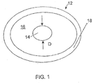
- FIGURE 1 schematically illustrates a cross section of an optical fiber 12, taken perpendicular to the longitudinal axis along which the fiber 12 extends.
- the optical fiber 12 of FIGURE 1 can include a core 14 and a cladding 16 disposed about the core 14.
- the cladding 16 contactingly surrounds the core 14 and tends to confine optical energy propagated by the optical fiber 12 to the core 14 for guidance thereby, such as by via the phenomenon of total internal reflection.
- the optical fiber 12 can include at least one additional region 18 disposed about the cladding 16.
- the region 18 shown in FIGURE 1 can represent a second cladding disposed about the cladding 16 for tending to confine optical energy, such as pump optical energy, to the cladding 16 for guidance thereby.
- Such a fiber is referred to in the art as a "cladding pumped” or “double-clad” optical fiber, and the cladding 16 can be referred to as a "pump cladding.”
- the second cladding can comprise, for example, a glass or a fluorinated low index polymer coating applied and cured during draw of the optical fiber 12.
- the region 18 can represent a high index polymer protective region, typically comprising an outer higher modulus layer disposed over an inner lower modulus layer.
- One or both of the layers can be applied as coatings to the optical fiber as part of the draw process. Variations of the foregoing are of course possible.
- the region 18 can comprise a glass second cladding for tending to confine pump light to the cladding 16,, and the region 18 can in turn have disposed thereabout a polymer protective region having one or more layers.
- the HOMs if excited, can degrade beam quality, as noted above.
- the LP 02 mode is the most problematic, because it shares with the fundamental mode a intensity profile that has a substantially central maxima such that excitation of the fundamental mode, such as by a simple splice to single mode fiber, could be very likely to excite the LP 02 mode.
- the LP 11 mode can be problematic.
- the core 14 can comprise an active material for providing optical energy (e.g., via the process of stimulated emission) responsive to the optical fiber 12 receiving pump optical energy having a pump wavelength.
- the active material can comprise a rare earth material, such as, for example, one or more of erbium, ytterbium, neodymium or thulium (e.g., a concentration of Er, Yb, Nd or Th ions).
- the core 14 is typically multimode, and has a diameter D that is larger than a standard single mode core (e.g., a 5 micron diameter core) to provide a fundamental mode having an increased mode field diameter (MFD).
- MFD mode field diameter
- the increased MFD can reduce power density and hence increase the power threshold for the onset of non-linear phenomena.
- the exact MFD can depend on other factors, such as refractive index profile, of course, but for many standard designs a larger diameter core will typically having a fundamental mode have a larger MFD.
- FIGURE 2 includes a plot of one possible refractive index profile for the core 14 and cladding 16 of the fiber 12 of FIGURE 1 , and also includes plots of nearest normalized intensity profiles for the fundamental and selected HOMs. (Intensities are normalized for each mode by setting the integral over r ⁇ dr ⁇ d ⁇ to 1.)
- the optical fiber 12 can support, in addition to the fundamental mode LP 01 indicated by reference numeral 36, multiple HOMs, such as the LP 11 mode indicated by reference numeral 38, the LP 21 mode indicated by reference numeral 40, and the LP 02 mode, indicated by reference numeral 42.
- the LP 02 mode comprises an intensity profile that does not include such a minima or null, and rather is substantially non-zero at its center, as indicated in FIGURE 2 by reference numeral 46.
- a substantially central maxima (which is typically absolute, not just local) is characteristic of modes of zero azimuthal order, at least for lower order modes.
- Azimuthal order refers to the value of the first subscript in the mode designation.
- the HOMs if excited, can degrade beam quality, as noted above.
- the LP 02 mode is the most problematic, because it shares with the fundamental mode a intensity profile that has a substantially central maxima such that excitation of the fundamental mode, such as by a simple splice to single mode fiber, could be very likely to excite the LP 02 mode.
- the LP 11 mode can be problematic.
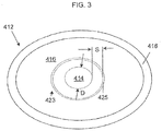
- the optical fiber 412 of FIGURE 3 which can be substantially similar to optical fiber 12 of FIGURE 1 , and hence can include some or all of the structural features thereof noted above.
- the optical fiber 412 includes a core 414, a cladding 416 disposed about the core 414, and, optionally, a second region 418 disposed about the cladding 416.
- the optical fiber 412 can further include at least one region 423 spaced from the core 414.
- the at least one region 423 comprises a ring core 425.
- the at least one region 423 can include an absorbing material for absorbing optical energy having a selected wavelength, such as, for example, the wavelength of operation of the optical fiber 412.
- the absorbing material is preferably of low absorption at the pump wavelength.
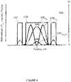
- FIGURE 4 plots one possible refractive index profile 430 for the optical fiber 412 and normalized intensity profiles for the fundamental and selected HOMs.
- the refractive index profile 430 includes an inner section 435 corresponding to the core 412 and outer sections 431 corresponding to the ring core 425. Sections of the refractive index profile between the section 435 (corresponding to the core) and the sections 431 (representative of the ring core 425 ) correspond to the cladding 416, as do sections outward of the sections 431. Cladding sections are not indicated by reference numerals in FIGURE 4 . Note that refractive profile section 435 and sections 431 can have substantially the same index difference with respect to the cladding.
- Reference numeral 436 indicates the fundamental mode LP 01
- reference numeral 438 indicates the HOM LP 11 , both of which are at least relatively similar to, respectively, the LP 01 and LP 11 modes of FIGURE 3 (indicated in FIGURE 4 by reference numerals 36 and 38, respectively).
- FIGURES 2 and 4 differ considerably in that the intensity profile of the LP 02 mode of FIGURE 2 , which had a substantially non-zero central portion, is largely absent from FIGURE 4 .
- the LP 02 mode of FIGURE 2 has been "converted" to a mixed mode of the core 414 and the at least one region 423 (or in any event the LP 02 seems to have disappeared and the mixed mode has appeared). Because the mixed mode has appropriate intensity in the ring core 425, it is substantially attenuated, including the intensity portion of the mixed mode present in the core 414, by the absorbing material comprised by the ring core 425.
- the fundamental mode LP 01 which is not a mixed mode, is largely unaffected, or at least any increase in attenuation thereof is easily accommodated and/or not overly detrimental in many practical applications.
- the optical fiber apparatus comprises a rare earth material that is to be pumped, it can be desirable to select an absorbing material that tends not to absorb the pump optical energy.
- Absorbing materials useful with typical rare earths include samarium, praseodymium or terbium. Sm 3+ and Pr 3+ ions, which have strong absorption around 1064 nm and 1030 nm, respectively, can be useful when the optical fiber apparatus include a rare earth material, such as ytterbium, providing light at around 1060 nm.
- Ytterbium can be pumped, for example, at 915, 940 or 975 nm, and, as one example, samarium and praseodymium have low absorption at 975 nm.
- Samarium can also be particularly useful when the rare earth material comprises neodymium or ytterbium and erbium.
- Terbium can be particularly useful when, for example, pumping the rare earth material thulium at 1576 nm and samarium when pumping at 790 nm.
- Thulium can provide optical energy at about 2000 nm, as is known in the art.
- the absorbing material can have concentration of, for example, about 500 ppm, about 1000 ppm, about 1500 ppm about 2000 ppm or greater than about 2000 ppm.
- the ring core can comprise a silica-based glass.
- the silica-based glass can comprise, for example, one or more of a concentration of aluminum, phosphorus, germanium or fluorine.
- the ring core comprises a concentration of phosphorus and fluorine, such as in a silica based glass; in another example, the ring core can comprise a concentration of aluminum and can include, for example, a concentration of germanium.
- a silica based glass can comprise the aluminum and germanium concentrations, and the absorbing material can comprise samarium. The concentration ranges specified above for the absorbing material can be useful for the Al, Ge, P and F materials noted above.
- Modeling indicates the attenuation of the mixed mode can be at least between one and two orders of magnitude greater that than of the fundamental mode, where the attenuation is specified in terms of dB/meter (e.g., tenths of a dB/meter for LP 01 compared to tens of dB/meter for the mixed mode to which the LP 02 mode is converted). See Table I below. Table I Modeled Losses of Fundamental and HOMs - Optical Fiber of Figs.
- the optical fiber of FIGURES 3 and 4 can provide fiber having the benefit of fundamental mode that has an increased mode field diameter, which reduces the core power density and allows higher power transmission before the onset of non linear phenomena.
- the optical fiber 412 can be configured and arranged, such as by, for example, selecting one or more of the composition, geometrical shape, location and refractive index profiles of the core 414 and/or ring 425, such that at the desired wavelength of operation the optical fiber 412 supports a fundamental mode and at least one HOM that is a mixed mode of the core and ring.
- the at least one HOM can be attenuated, while the fundamental mode can remain primarily a mode of the core 414.
- the cladding 416 can comprise glass, such as, for example, a silica-based glass. It is often desirable that the cladding 416 consist of or consist essentially of glass, such as a silica based glass or pure silica glass, to help ensure that the optical fiber 412 can handle high power levels of light having the pump wavelength, especially when the optical fiber 412 comprises a cladding pumped fiber.
- the cladding 416 can, in certain aspects of the disclosure, be substantially homogenous and (except for the presence of the at least one region that effects mixed modes and, if desired, stress inducing regions) and hence not be considered as including a "microstructure" for guiding optical energy.
- the modeled fiber has a core 14 having a diameter D of 19 microns having a step index profile 30, with the raised section corresponding to the refractive index of the core 14 and having an index difference ⁇ n of about 0.006 with respect to the cladding 16.
- Calculations were performed for an operating wavelength of about 1060 nm.
- the ring core 425 was considered as doped with about 1000 ppm of an absorbing material (samarium).
- the index difference or ⁇ between the ring sections 431 (or more generally between the at least one region) and the cladding was also considered as about 0.006, but more generally need not be equal to the ⁇ between the core section 425 and the cladding.
- the ⁇ between the ring section and cladding can be less than, substantially equal to, or greater than the ⁇ between the core section 425 and the cladding.
- optical fibers having one or more mixed modes as well one or more modes that are primarily of the core or that at the least one region are provided below.
- different fiber designs are considered.
- a fiber generally as shown in FIGURES 3 and 4 and having a central core having a diameter of 21 ⁇ m and a ring core having an inner radius of 16 ⁇ m and an outer radius of 21 ⁇ m.
- the fiber has a step refractive profile generally as shown in FIGURE 4 with a ⁇ n for the central core and ring core of 0.0025.
- the index of refraction of the cladding is 1.44968 at a wavelength of 1060 nm.
- the core considered individually, has a numerical aperture (NA) of 0.085 and V-number at 1060 nm of 5.30.
- Modes are ordered by their effective index value, with higher order modes having lower effective indices. Modes having an effective index greater than that of the cladding are considered guided. Odd and even degenerate modes are indicated by "o" and "e” subscripts, respectively. Only one calculation is made where values are expected to be the same for the odd and even modes.
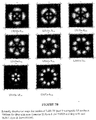
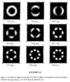
- FIGURE 5 shows two dimensional intensity distribution maps for the modes of Table II.
- the optical fiber can also be analyzed as if the ring core is present and the core is absent.
- Table III presents the results of such an analysis, and FIGURE 6 shows intensity maps for the modes of Table III. This analysis is referred to herein as "individual ring core” analysis and the modes as “ring core” or “ring” modes.
- n clad 1.44968 at 1060nm.
- Table IV below tabulates modeling analysis of the actual optical fiber, that is, where the central and the ring core are both present.
- FIGURE 7 shows two dimensional intensity distribution maps for the modes of the actual fiber analysis of Table IV.
- n clad 1.44968 at 1060nm.
- a mode identified in an actual fiber analysis is a mixed mode wherein particular modes identified in individual analyses have mixed: (1) the intensity map for the actual fiber appears to be a combination of the individual intensity maps of the individual modes that are mixing to form the mixed mode; (2) the modes that are mixing are of the same azimuthal order; and (3) whereas the modes considered individually might not have intensities in the core and ring core that are of the same order of magnitude (as can be indicated by the overlap integrations being of the same order), for the mixed mode intensities are of the same order. "Of the same order,” for the purposes of (3), means that the larger quantity is no greater than about six times the smaller quantity. Also, an additional criteria can be that the individual modes of the core and of the at least one region should have effective indices that are not too disparate.
- the effective refractive index of the LP 02 core mode (1.45040) is substantially the same as that of the effective refractive index of the R 01 ring core mode (1.45041).
- both the modes are of the same (zero in this case) azimuthal order.
- FIGURES 7A and 7B include intensity maps that bear a strong resemblance to each intensity maps for individual core modes or intensity maps for individual ring modes, FIGURES 7A and 7B do not include an analog to the LP 02 core mode.
- the intensity maps for modes LP (1) - LP (5) of the actual fiber analysis of FIGURE 7A each bear a strong resemblance to the intensity maps for the modes LP (1) - LP (5) of the core analysis of FIGURE 5 .
- the LP (6) mode of the actual analysis of FIGURE 7A does not resemble any one core mode intensity map of FIGURE 5 or ring core mode intensity map of FIGURE 6 , but rather appears to be a combination of the LP 02 core mode (LP (6) of the individual core analysis of FIGURE 5 ) and the R 01 (LP (1) of the individual ring core analysis of FIGURE 6 ).
- the overlap integrals of Tables II-IV confirm that the LP (6) actual fiber mode is a mixed mode of the LP 02 core mode and the R 01 ring core mode.
- the overlap for the R 01 ring core mode with the ring core is approximately 500 times the overlap with the core
- the overlap of LP 02 core with the core is approximately 50 times the overlap with the ring core
- the ratio of the larger overlap value to the smaller overlap value for the LP (6) actual mode is now reduced to 1.1563, indicating a close to even distribution between the core and ring core.
- the LP 02 core mode and R 01 ring mode mix to form two mixed modes - the LP(6) and LP(9) modes of Table IV and FIGURE 7A .
- Inclusion of absorbing material in the ring core should suppress this mixed mode, yet leave the LP (1), or LP 01 , fundamental actual fiber mode far less attenuated, as it primarily a mode of the core (as are the core modes LP (2) - LP (6), which modes include modes corresponding to the LP 11 and LP 21 odd and even modes of the core).
- HOMs can have intensity profiles that appear to be a mixture core and cladding modes, yet that are not considered to be mixed modes.
- LP (10) of FIGURE 7B appears to be a combination of the LP(4), or R 21o , ring core mode of FIGURE 6 and the LP(4), or LP 21o , core mode of FIGURE 5 .
- the effective refractive indices of the R 21o mode (1.45029) is not that close to that of the LP 21o mode (1.45069), and most importantly the values for the overlap integrals for the LP (10) actual fiber HOM differ by a factor of about 100 (see Table IV), with the vast majority of the intensity overlapping with the ring core.
- the azimuthal order of the R 21o and LP 21o modes is the same, and both are of the odd orientation, they are not considered to be mixing to form a mixed mode, despite the LP(10) actual fiber intensity distribution appearing to be a direct combination of R 21o ring core mode and the LP 21o cladding mode.
- the LP (10) actual fiber mode appears to be primarily a mode of the ring core, despite the added features of intensity map.
- a mode such at the LP(10) is referred to herein as a "composite mode," because of the appearance of the intensity map, but not a mixed mode.
- one approach to mixing a selected mode of region for example, a selected mode of the core (perhaps so that it can be suppressed) is to design the ring core such that a ring mode of the same azimuthal order as the targeted core mode has a similar effective index to that of the targeted core mode.
- Analysis of the actual fiber data can confirm the existence of the mixed mode. Iterations can be performed as necessary, varying one or more of the geometry of the core and ring cores, spacing therebetween, refractive index profiles, etc. to arrive at the design where the desired modes mix to form a desired mixed mode.
- an absorbing material comprised in one of the regions can be ascertained to establish suppression of a mode or to further confirm that a mode is a mixed mode or primary mode.
- absorbing material in the ring core should affect mixed modes and modes that are primarily of the ring core, but typically do not substantially affect modes that are primarily modes of the core.
- the LP 02 core mode is mixed with ring core modes to form an actual mode, but no attempt was made to mix the LP 11 core modes.
- Data demonstrating an optical fiber wherein the LP 11 core modes mix with ring core modes to form mixed modes are presented in Tables V-VII and FIGURES 8-10 . The procedure follows that described above in conjunction with Tables II-IV and FIGURES 5-7B .
- the core considered alone, has a numerical aperture (NA) of 0.093 and a V-number of 3.87.
- the optical fiber includes a ring core having an inner radius of 14 ⁇ m and an outer radius of 20 ⁇ m, and a ⁇ n with respect to the cladding of 0.00215.
- Table V presents the individual core analysis, and FIGURE 8 shows the corresponding intensity maps for the modes presented in Table V;
- Table VI presents the ring core considered individually, and
- FIGURE 9 shows the corresponding intensity maps for the modes of table VI;
- Table VII presents actual fiber mode data, with FIGURE 10 presenting the intensity distribution maps for actual fiber modes of the Table VII.
- n clad 1.44968 at 1060nm.
- NA 0.093.
- V 3.87.
- n clad 1.44968 at 1060nm.
- LP mode Mode Type Mode Effective refractive index Mode overlap integral with core Mode overlap integral with ring 1 LP 01 1.45182 0.94077 0.00038 2 (LP 11 -R 11 ) m1o 1.45129 - - 3 (LP 11 -R 11 ) m1e 1.45129 0.39740 0.39548 4 R 01 1.45063 0.00258 0.80793 5 (LP 11 -R 11 ) m2o 1.45062 - - 6 (LP 11 -R 11 )) m2e 1.45047 0.42913 0.42612 7 R 21o 1.45027 0.00146 0.80846 8 R 21e 1.45027 - - 9 R 31o 1.45020 0.00027 0.81170 10 R 31e 1.45016 - - 11 R 41o 1.45015 0.00005 0.80919 12 R 41e 1.45008 - - 13 R 51o 1.45008 0.00001 0.79953 14 R 51e
- LP 11o and LP 11e core modes have substantially the same effective indices as the R 11e and R 11o ring core modes.
- the modes are of the same azimuthal order (azimuthal order is 1 in this case).
- the odd modes and even modes each mix to form two mixed actual fiber modes, resulting in a total of four mixed modes. That is, LP 11o mixes with R 11o to form the mixed modes LP (2) and LP (5) of Table VII and FIGURE 10 (labeled (LP 11 - R 11 ) m1o and (LP 11 - R 11 ) m2o , respectively).
- the LP 11e core mode mixes with the R 11e ring core mode to form the LP(3) and LP(6) mixed actual fiber modes indicated in Table VII and FIGURE 10 (labeled LP 11 - R 11 ) m1e and (LP 11 - R 11 ) m2e. , respectively).
- the mode field distribution maps of the actual fiber LP (2) and LP (5) modes appear to be logical combinations of the LP 11o and R 11o modes, and the mode field distribution maps for the LP (3) and LP (7) modes appear as one would expect for combinations of the LP 11e and R 11e modes.
- Consideration of the overlap integrals also supports the formation of the identified mixed modes.
- the overlap integrals for the LP (2), LP(3), LP(5) and LP(7) actual fiber modes have ratios of the higher to lower value on the order of 1, indicating nearly equal distribution in the core and ring core.
- the LP 21 core modes (i.e., the LP 21o and LP 21e core modes) of Table V have effective refractive indices (1.44978, 1.44979) that are nearly identical those of the R 61 ring core modes (1.44978) of Table VI.
- This insight -- that matching azimuthal order can greatly facilitate selecting modes for mode mixing and is, at least in some circumstances, more important than strict effective index matching and can be a condition for modes to mix -- does not appear to be appreciated by the prior art.
- the teachings herein could be applied, in certain circumstances, to favoring a selected HOM over another HOM at the expense, perhaps, of the fundamental mode. Such an approach is within the scope of the disclosure. It is also considered within the scope of the present disclosure to have both the core LP 11 and LP 02 modes mix with ring core modes to form mixed modes.
- the design may include two ring cores, one surrounding another, where the core LP 11 mode mixes with a mode of one ring core and the core LP 02 mode mixes with a mode of the other ring core.
- the core LP 02 can mix with the ring R 02 ring core mode and the core LP 11 mix with a mode of the ring core having a lower order than the R 02 mode.
- HOMs in many applications, are much more likely to be problematic than others, and, accordingly it may not be as important to address those that are less important in the same manner as those that are more problematic.
- a splice from an SM fiber to a MM fiber is much more likely to excite a HOM having an intensity distribution map that is also substantially central and azimuthally symmetric than other HOMs that are not substantially central and azimuthally symmetric. For example, such a splice is considered more likely to excite the LP 02 mode shown in FIGURE 3 than the LP 11 mode.
- V-number and NA are parameters that are often specified for an optical fiber. Unless otherwise specified, V-number and NA of the core refer to the V-number and the NA of the core considered individually, that is, without consideration of the at least one region that does contribute to the formation of mixed modes.
- the a fiber can be "microstructured," that is, can include features, such as an array of longitudinally extending index modified regions (e.g., an array of voids having an index of refraction different than that of the material defining the voids) that provide a photonic bandgap effect or that macroscopically change the average index of the cladding via a weighted average analysis of the indices of refraction of the silica regions and index modified regions.
- the core is still considered to be by total internal reflection (TIR).
- TIR total internal reflection
- Microstructured fibers are considered to be within the scope of the present disclosure.
- the "ring" can be formed by leaving out the voids in an annular region disposed about the core.
- analysis of the core individually would include the cladding including the voids (and with the ring including the otherwise missing voids), and a mode considered to be guided "primarily" by the core would of course be affected by the voids.
- an optical fiber according to the present disclosure can comprise a core, a cladding disposed about the core, and optionally a region disposed about the cladding.
- the optical fiber can include at least one region spaced from the core, where the at least one region can comprise a plurality of satellite regions, which can be individual longitudinally extending voids or index modified regions arranged in a ring or other configuration.
- an optical fiber according to the present disclosure can have a core having a V-number at the wavelength of operation of the fiber of no less than 4.0; no less than 5.0; no less than 6.0; no less than 7.0; or no less than 7.5.
- the V-number can be from 3.0 to 5.0; from 5.0 to 7.0; or from 7.0 to 10.0.
- the V-number is not greater than 3, not greater than 3.5, not greater than 4, not greater than 4.5, not greater than 5, or not greater than 5.5.
- the core of a fiber can have an NA of no less than 0.12, no less than 0.15, no less than 0.16, or no less than 0.17 at the wavelength of operation of the optical fiber.
- the NA of the core can be about 0.17.
- the core of a fiber can have a diameter of at least 15 microns; at least 20 microns; at least 25 microns; at least 30 microns; at least 35 microns; at least 40 microns; or at least 50 microns.
- FIGURE 11 schematically illustrates a cross section of an optical fiber 1012 according to the disclosure that includes, in addition to a core 1014 and at least one region 1023 spaced from the core 1014, a pair of longitudinally, or axially, extending stress inducing regions, indicated by reference numerals 1033A and 1033B.
- the stress inducing regions 1033A and 1033B can help induce selected birefringence in the optical fiber, such as, for example, via the stress-optic effect.
- the stress inducing regions can have a thermal coefficient of expansion selected to be different than that of the material of the fiber disposed about the stress inducing regions such that when fiber cools after being drawn stresses are permanently induced.
- Birefringence refers to at least a region of the fiber, such as, for example, the core 1014, having a substantially different refractive index for one polarization of light than for the orthogonal polarization of light.
- the fiber 1012 can be a polarization maintaining fiber or a polarizing fiber, depending, at least in part, on the choice of one or more of composition, shape and location of the stress inducing regions.
- the index of refraction of the stress inducing regions 1033 can be adjusted, via the use of various dopants, including, for example, those noted above, to be lower than that of the cladding 1016, substantially matched to that of the cladding 1016, or even to be higher than that of the cladding 1016.
- FIGURE 12 shows a perspective view schematically illustrating one example of an optical fiber apparatus according to the disclosure.
- the optical apparatus 1110 can include a first optical fiber 1112 that can include, as described above, a core 1114, a cladding 1116 disposed about the core 1114, and at least one region 1123 spaced from the core 1114 for supporting selected mixed modes with the core 1114.
- the optical fiber 1112 can have a wavelength of operation and can include a rare earth material for providing optical energy having the wavelength of operation responsive to the optical fiber 1114 receiving pump optical energy having a pump wavelength.
- the optical fiber apparatus 1110 can include a second optical fiber 1135 located alongside the first optical fiber, and the second optical fiber can include at least a core 1137.
- the optical fiber apparatus 1110 can include a common cladding 1145 disposed about the first and second optical fibers.
- the common cladding 1145 can be constructed and arranged so as to tend to confine optical energy to the core 1137 of the second optical fiber 1135 for guidance by the core 1137.
- the second optical fiber 1135 can propagate pump optical energy and the first and second optical fiber located alongside one another, as shown in FIGURE 10 , such that the pump optical energy couples to the first optical fiber 1112 for optically pumping the rare earth material comprised by, for example, the core 1114 of the first optical fiber 1112.
- the first and second optical fibers, 1112 and 1135, respectively, can be drawn together within the common cladding 1145.
- the optical apparatus 1110 can be constructed and arranged such that the first and second optical fibers can be accessed individually at the ends of a length of the optical fiber apparatus 1110 so as to, for example, couple pump optical energy to the second optical fiber for subsequent coupling to the first optical fiber and to deliver a signal to and/or extract a signal from the core 1114 of the first optical fiber 1112.
- An optical fiber apparatus can be configured, according to one aspect of the disclosure, as a laser.
- a laser can comprise at least one reflector, which can comprise a grating, such as, for example, a Bragg grating formed via the selective application of actinic radiation to, for example, a photosensitive section of optical fiber.
- the laser can comprise a second reflector.
- One of the reflectors is usually less reflective than the other of the reflectors, as is known in the art.
- Two spaced reflectors can form a laser cavity therebetween.
- the laser can also be configured as a distributed feedback (DFB) laser, and can use a distributed reflector, typically in the form of one grating having a phase change therein, and can provide narrow linewidth light.
- DFB distributed feedback
- a laser can also be configured in a master oscillator-power amplifier (MOPA) arrangement, where a master oscillator, such as a diode or fiber laser, seeds an optical fiber amplifier.
- Optical fiber apparatus can include a fiber optical coupler for coupling pump light to the optical fiber apparatus.
- an optical fiber can comprise a rare earth material for providing light of a first wavelength responsive to the fiber receiving (e.g., being “pumped by") light of a second wavelength (e.g., "pump light”).
- "Rare earth material” means one or more rare earths, typically included in the fiber in the form of rare earth ions.
- the rare earths can be selected by those of ordinary skill in the art of the field of pumped fibers, for example from the Lanthanide group of elements in the periodic table (materials having the atomic numbers 57 - 71).
- the optical fiber can be pumped as shown in FIGURE 8 and discussed above.
- the optical fiber can be "end-pumped” as is known in the art, and can include a second, or "pump” cladding for propagating the pump light delivered to the optical fiber via the end pumping.
- the refractive index profiles shown in the foregoing FIGURES are idealized. Actual refractive index profiles measured on a preform or from an actual optical fiber drawn from the preform can include other features, as is well known in the art, such as rounded edges between sections and the signature "dip" in the index of refraction of the core due to the burnoff of dopants in the core during the collapse stage of the Modified Chemical Vapor Deposition (MCVD) process (assuming that the MCVD process is used to fabricate the optical fiber preform). Also, some of the sections of the refractive index profile corresponding to a particular region of the fiber are drawn to portray the index of refraction as substantially constant for the region. This need not be true in all practices of the disclosure.
- MCVD Modified Chemical Vapor Deposition
- the index of refraction of a region of a fiber need not be constant, and can be varied according to a predetermined function to provide a particular result.
- a core comprising a graded refractive index profile, where the profile corresponds to a parabola or other suitable function.
- recitation that an apparatus includes "at least one widget” and subsequent recitation that "said at least one widget is colored red” does not mean that the claim requires all widgets of an apparatus that has more than one widget to be red.
- the claim shall read on an apparatus having one or more widgets provided simply that at least one of the widgets is colored red.
Landscapes
- Physics & Mathematics (AREA)
- General Physics & Mathematics (AREA)
- Optics & Photonics (AREA)
- Lasers (AREA)
- Light Guides In General And Applications Therefor (AREA)
Claims (9)
- Appareil à fibre optique ayant une longueur d'onde de fonctionnement, comprenant :une fibre optique, ladite fibre optique comprenant une âme comprenant une matière active pour fournir de la lumière ayant la longueur d'onde de fonctionnement en réponse audit appareil optique recevant de l'énergie optique de pompage ayant une longueur d'onde de pompage ;une gaine disposée autour de ladite âme ;au moins une zone espacée par rapport à ladite âme, dans lequel ladite au moins une zone comprend une zone de forme annulaire ; etdans lequel ladite fibre optique est configurée et étudiée de telle sorte qu'à ladite longueur d'onde de fonctionnement, ladite fibre optique peut propager une pluralité de modes, et dans lequel ladite fibre optique comprend un mode fondamental qui est principalement un mode de ladite âme et au moins un mode d'ordre supérieur (HOM) qui est un mode mélangé d'un mode sélectionné de ladite âme et d'un mode sélectionné de ladite au moins une zone.
- Appareil à fibre optique selon la revendication 1, dans lequel ladite matière active comprend une matière de terres rares.
- Appareil à fibre optique selon la revendication 2, dans lequel ladite au moins une zone comprend une matière absorbante pour absorber de l'énergie optique ayant la longueur d'onde de fonctionnement et, si absorbante d'énergie optique ayant la longueur d'onde de pompage, a une absorption plus élevée pour de l'énergie optique ayant la longueur d'onde de fonctionnement que pour de l'énergie optique ayant la longueur d'onde de pompage.
- Appareil à fibre optique selon la revendication 1, dans lequel ledit au moins un HOM comprend un HOM d'ordre azimutal nul.
- Appareil à fibre optique selon la revendication 1, dans lequel ledit mode sélectionné de ladite âme comprend le mode d'âme LP02.
- Appareil à fibre optique selon la revendication 1, dans lequel ledit au moins un HOM comprend un HOM d'ordre azimutal non nul.
- Appareil optique selon la revendication 1, dans lequel ledit mode sélectionné de ladite âme comprend le mode LP11.
- Appareil à fibre optique selon la revendication 1, dans lequel ladite fibre optique comprend au moins une zone, induisant une contrainte, s'étendant longitudinalement ayant un coefficient d'expansion thermique différent d'une matière de ladite fibre optique disposée autour de ladite zone induisant une contrainte, ladite zone induisant une contrainte servant à augmenter la biréfringence de ladite fibre optique.
- Appareil à fibre optique selon la revendication 1, dans lequel ledit appareil est configuré en tant que laser à fibre.
Applications Claiming Priority (4)
| Application Number | Priority Date | Filing Date | Title |
|---|---|---|---|
| US12/580,223 US8285101B2 (en) | 2009-10-15 | 2009-10-15 | Optical fiber apparatus with suppression of higher order modes |
| US12/580,358 US8139912B2 (en) | 2009-10-15 | 2009-10-16 | Double clad optical fiber having ring core surrounding core for high power operation |
| US12/607,500 US8204349B2 (en) | 2009-10-28 | 2009-10-28 | Optical fiber with multiple ring-shaped core regions |
| PCT/US2010/052480 WO2011047027A2 (fr) | 2009-10-15 | 2010-10-13 | Appareil à fibre optique avec suppression des modes d'ordre supérieur |
Publications (3)
| Publication Number | Publication Date |
|---|---|
| EP2488904A2 EP2488904A2 (fr) | 2012-08-22 |
| EP2488904A4 EP2488904A4 (fr) | 2017-07-19 |
| EP2488904B1 true EP2488904B1 (fr) | 2019-03-27 |
Family
ID=46512880
Family Applications (1)
| Application Number | Title | Priority Date | Filing Date |
|---|---|---|---|
| EP10824007.8A Active EP2488904B1 (fr) | 2009-10-15 | 2010-10-13 | Appareil à fibre optique avec suppression des modes d'ordre supérieur |
Country Status (3)
| Country | Link |
|---|---|
| EP (1) | EP2488904B1 (fr) |
| CN (1) | CN102939552B (fr) |
| WO (1) | WO2011047027A2 (fr) |
Families Citing this family (2)
| Publication number | Priority date | Publication date | Assignee | Title |
|---|---|---|---|---|
| JP6268232B2 (ja) * | 2016-07-04 | 2018-01-24 | 株式会社フジクラ | 光ファイバ、及び、レーザ装置 |
| US10466412B1 (en) | 2018-08-31 | 2019-11-05 | Nexans | Selective mode suppressing multi-mode fiber optic cable for increased bandwidth |
Family Cites Families (11)
| Publication number | Priority date | Publication date | Assignee | Title |
|---|---|---|---|---|
| US6535679B2 (en) * | 1997-01-16 | 2003-03-18 | Sumitomo Electric Industries, Ltd. | Optical fiber and method of manufacturing the same |
| US6327403B1 (en) * | 1999-06-10 | 2001-12-04 | Lasercomm Inc. | Reducing mode interference in transmission of LP02 Mode in optical fibers |
| US20020164140A1 (en) * | 2000-01-12 | 2002-11-07 | Michael Lysiansky | Few-mode fiber profile |
| US6496301B1 (en) | 2000-03-10 | 2002-12-17 | The United States Of America As Represented By The Secretary Of The Navy | Helical fiber amplifier |
| US6810185B2 (en) * | 2002-01-31 | 2004-10-26 | Corning Incorporated | Higher order mode stripping optical fiber and modules and systems utilizing the same |
| US7424193B2 (en) | 2004-07-14 | 2008-09-09 | The Regents Of The University Of Michigan | Composite waveguide |
| US7526167B1 (en) * | 2005-06-24 | 2009-04-28 | Lockheed Martin Corporation | Apparatus and method for a high-gain double-clad amplifier |
| CN1971323A (zh) * | 2006-12-13 | 2007-05-30 | 中国科学院上海光学精密机械研究所 | 大模场双包层单模光纤 |
| US7455460B2 (en) * | 2007-03-08 | 2008-11-25 | Panduit Corp. | Fiber optic connector with double-clad stub fiber |
| WO2009014623A1 (fr) | 2007-07-20 | 2009-01-29 | Corning Incorporated | Fibre optique à grande surface modale |
| CN101408641B (zh) * | 2008-11-06 | 2010-12-15 | 燕山大学 | 锥形微结构光纤高阶模滤波器 |
-
2010
- 2010-10-13 WO PCT/US2010/052480 patent/WO2011047027A2/fr not_active Ceased
- 2010-10-13 CN CN201080057196.8A patent/CN102939552B/zh active Active
- 2010-10-13 EP EP10824007.8A patent/EP2488904B1/fr active Active
Non-Patent Citations (1)
| Title |
|---|
| None * |
Also Published As
| Publication number | Publication date |
|---|---|
| WO2011047027A2 (fr) | 2011-04-21 |
| CN102939552B (zh) | 2015-06-17 |
| EP2488904A4 (fr) | 2017-07-19 |
| WO2011047027A3 (fr) | 2014-11-20 |
| EP2488904A2 (fr) | 2012-08-22 |
| CN102939552A (zh) | 2013-02-20 |
Similar Documents
| Publication | Publication Date | Title |
|---|---|---|
| US8285101B2 (en) | Optical fiber apparatus with suppression of higher order modes | |
| EP3397999B1 (fr) | Systèmes utilisant fibres optiques à mélange de modes | |
| EP1242325B1 (fr) | Fibre optique presentant des irregularites au niveau de la limite de la gaine et son procede de fabrication | |
| EP2703854B1 (fr) | Fibres double plaque produisant un gain présentant une meilleure absorption de gainage tout en conservant un fonctionnement monomode | |
| JP5415553B2 (ja) | 改良されたクラッドポンプ光導波路 | |
| US8031999B2 (en) | Photonic band-gap fiber | |
| US9366806B2 (en) | Gain-producing fibers with increased cladding absorption while maintaining single-mode operation | |
| CN105826798A (zh) | 高功率单模纤维源 | |
| WO2010055700A1 (fr) | Fibre optique dopée à l’ytterbium, laser à fibre et amplificateur à fibres | |
| US8204349B2 (en) | Optical fiber with multiple ring-shaped core regions | |
| EP3583666B1 (fr) | Systèmes et procédés d'amplification optique | |
| US8611002B2 (en) | Optical fiber lasers and amplifiers and methods for providing optical gain | |
| EP2488904B1 (fr) | Appareil à fibre optique avec suppression des modes d'ordre supérieur | |
| JP6306637B2 (ja) | シングルモード動作を維持したままクラッド吸収を増加させた利得をもたらすファイバ | |
| WO2014197052A2 (fr) | Fibres optiques à plusieurs cœurs | |
| US20160282553A1 (en) | Optical fiber with mosaic fiber | |
| WO2017143429A1 (fr) | Fabrication de fibres optiques à saillies longitudinales rompant la symétrie |
Legal Events
| Date | Code | Title | Description |
|---|---|---|---|
| PUAI | Public reference made under article 153(3) epc to a published international application that has entered the european phase |
Free format text: ORIGINAL CODE: 0009012 |
|
| 17P | Request for examination filed |
Effective date: 20120605 |
|
| AK | Designated contracting states |
Kind code of ref document: A2 Designated state(s): AL AT BE BG CH CY CZ DE DK EE ES FI FR GB GR HR HU IE IS IT LI LT LU LV MC MK MT NL NO PL PT RO RS SE SI SK SM TR |
|
| DAX | Request for extension of the european patent (deleted) | ||
| R17D | Deferred search report published (corrected) |
Effective date: 20141120 |
|
| A4 | Supplementary search report drawn up and despatched |
Effective date: 20170619 |
|
| RIC1 | Information provided on ipc code assigned before grant |
Ipc: G02B 6/14 20060101ALI20170612BHEP Ipc: G02B 6/02 20060101AFI20170612BHEP |
|
| STAA | Information on the status of an ep patent application or granted ep patent |
Free format text: STATUS: EXAMINATION IS IN PROGRESS |
|
| 17Q | First examination report despatched |
Effective date: 20180430 |
|
| GRAP | Despatch of communication of intention to grant a patent |
Free format text: ORIGINAL CODE: EPIDOSNIGR1 |
|
| STAA | Information on the status of an ep patent application or granted ep patent |
Free format text: STATUS: GRANT OF PATENT IS INTENDED |
|
| INTG | Intention to grant announced |
Effective date: 20181120 |
|
| GRAS | Grant fee paid |
Free format text: ORIGINAL CODE: EPIDOSNIGR3 |
|
| GRAA | (expected) grant |
Free format text: ORIGINAL CODE: 0009210 |
|
| STAA | Information on the status of an ep patent application or granted ep patent |
Free format text: STATUS: THE PATENT HAS BEEN GRANTED |
|
| AK | Designated contracting states |
Kind code of ref document: B1 Designated state(s): AL AT BE BG CH CY CZ DE DK EE ES FI FR GB GR HR HU IE IS IT LI LT LU LV MC MK MT NL NO PL PT RO RS SE SI SK SM TR |
|
| REG | Reference to a national code |
Ref country code: GB Ref legal event code: FG4D |
|
| REG | Reference to a national code |
Ref country code: CH Ref legal event code: EP |
|
| REG | Reference to a national code |
Ref country code: AT Ref legal event code: REF Ref document number: 1113765 Country of ref document: AT Kind code of ref document: T Effective date: 20190415 |
|
| REG | Reference to a national code |
Ref country code: IE Ref legal event code: FG4D |
|
| REG | Reference to a national code |
Ref country code: DE Ref legal event code: R096 Ref document number: 602010057893 Country of ref document: DE |
|
| PG25 | Lapsed in a contracting state [announced via postgrant information from national office to epo] |
Ref country code: LT Free format text: LAPSE BECAUSE OF FAILURE TO SUBMIT A TRANSLATION OF THE DESCRIPTION OR TO PAY THE FEE WITHIN THE PRESCRIBED TIME-LIMIT Effective date: 20190327 Ref country code: SE Free format text: LAPSE BECAUSE OF FAILURE TO SUBMIT A TRANSLATION OF THE DESCRIPTION OR TO PAY THE FEE WITHIN THE PRESCRIBED TIME-LIMIT Effective date: 20190327 Ref country code: FI Free format text: LAPSE BECAUSE OF FAILURE TO SUBMIT A TRANSLATION OF THE DESCRIPTION OR TO PAY THE FEE WITHIN THE PRESCRIBED TIME-LIMIT Effective date: 20190327 Ref country code: NO Free format text: LAPSE BECAUSE OF FAILURE TO SUBMIT A TRANSLATION OF THE DESCRIPTION OR TO PAY THE FEE WITHIN THE PRESCRIBED TIME-LIMIT Effective date: 20190627 |
|
| REG | Reference to a national code |
Ref country code: NL Ref legal event code: MP Effective date: 20190327 |
|
| PG25 | Lapsed in a contracting state [announced via postgrant information from national office to epo] |
Ref country code: LV Free format text: LAPSE BECAUSE OF FAILURE TO SUBMIT A TRANSLATION OF THE DESCRIPTION OR TO PAY THE FEE WITHIN THE PRESCRIBED TIME-LIMIT Effective date: 20190327 Ref country code: HR Free format text: LAPSE BECAUSE OF FAILURE TO SUBMIT A TRANSLATION OF THE DESCRIPTION OR TO PAY THE FEE WITHIN THE PRESCRIBED TIME-LIMIT Effective date: 20190327 Ref country code: GR Free format text: LAPSE BECAUSE OF FAILURE TO SUBMIT A TRANSLATION OF THE DESCRIPTION OR TO PAY THE FEE WITHIN THE PRESCRIBED TIME-LIMIT Effective date: 20190628 Ref country code: RS Free format text: LAPSE BECAUSE OF FAILURE TO SUBMIT A TRANSLATION OF THE DESCRIPTION OR TO PAY THE FEE WITHIN THE PRESCRIBED TIME-LIMIT Effective date: 20190327 Ref country code: NL Free format text: LAPSE BECAUSE OF FAILURE TO SUBMIT A TRANSLATION OF THE DESCRIPTION OR TO PAY THE FEE WITHIN THE PRESCRIBED TIME-LIMIT Effective date: 20190327 Ref country code: BG Free format text: LAPSE BECAUSE OF FAILURE TO SUBMIT A TRANSLATION OF THE DESCRIPTION OR TO PAY THE FEE WITHIN THE PRESCRIBED TIME-LIMIT Effective date: 20190627 |
|
| REG | Reference to a national code |
Ref country code: AT Ref legal event code: MK05 Ref document number: 1113765 Country of ref document: AT Kind code of ref document: T Effective date: 20190327 |
|
| PG25 | Lapsed in a contracting state [announced via postgrant information from national office to epo] |
Ref country code: PT Free format text: LAPSE BECAUSE OF FAILURE TO SUBMIT A TRANSLATION OF THE DESCRIPTION OR TO PAY THE FEE WITHIN THE PRESCRIBED TIME-LIMIT Effective date: 20190727 Ref country code: ES Free format text: LAPSE BECAUSE OF FAILURE TO SUBMIT A TRANSLATION OF THE DESCRIPTION OR TO PAY THE FEE WITHIN THE PRESCRIBED TIME-LIMIT Effective date: 20190327 Ref country code: AL Free format text: LAPSE BECAUSE OF FAILURE TO SUBMIT A TRANSLATION OF THE DESCRIPTION OR TO PAY THE FEE WITHIN THE PRESCRIBED TIME-LIMIT Effective date: 20190327 Ref country code: RO Free format text: LAPSE BECAUSE OF FAILURE TO SUBMIT A TRANSLATION OF THE DESCRIPTION OR TO PAY THE FEE WITHIN THE PRESCRIBED TIME-LIMIT Effective date: 20190327 Ref country code: CZ Free format text: LAPSE BECAUSE OF FAILURE TO SUBMIT A TRANSLATION OF THE DESCRIPTION OR TO PAY THE FEE WITHIN THE PRESCRIBED TIME-LIMIT Effective date: 20190327 Ref country code: SK Free format text: LAPSE BECAUSE OF FAILURE TO SUBMIT A TRANSLATION OF THE DESCRIPTION OR TO PAY THE FEE WITHIN THE PRESCRIBED TIME-LIMIT Effective date: 20190327 Ref country code: IT Free format text: LAPSE BECAUSE OF FAILURE TO SUBMIT A TRANSLATION OF THE DESCRIPTION OR TO PAY THE FEE WITHIN THE PRESCRIBED TIME-LIMIT Effective date: 20190327 Ref country code: EE Free format text: LAPSE BECAUSE OF FAILURE TO SUBMIT A TRANSLATION OF THE DESCRIPTION OR TO PAY THE FEE WITHIN THE PRESCRIBED TIME-LIMIT Effective date: 20190327 |
|
| PG25 | Lapsed in a contracting state [announced via postgrant information from national office to epo] |
Ref country code: PL Free format text: LAPSE BECAUSE OF FAILURE TO SUBMIT A TRANSLATION OF THE DESCRIPTION OR TO PAY THE FEE WITHIN THE PRESCRIBED TIME-LIMIT Effective date: 20190327 Ref country code: SM Free format text: LAPSE BECAUSE OF FAILURE TO SUBMIT A TRANSLATION OF THE DESCRIPTION OR TO PAY THE FEE WITHIN THE PRESCRIBED TIME-LIMIT Effective date: 20190327 |
|
| PG25 | Lapsed in a contracting state [announced via postgrant information from national office to epo] |
Ref country code: AT Free format text: LAPSE BECAUSE OF FAILURE TO SUBMIT A TRANSLATION OF THE DESCRIPTION OR TO PAY THE FEE WITHIN THE PRESCRIBED TIME-LIMIT Effective date: 20190327 Ref country code: IS Free format text: LAPSE BECAUSE OF FAILURE TO SUBMIT A TRANSLATION OF THE DESCRIPTION OR TO PAY THE FEE WITHIN THE PRESCRIBED TIME-LIMIT Effective date: 20190727 |
|
| REG | Reference to a national code |
Ref country code: DE Ref legal event code: R097 Ref document number: 602010057893 Country of ref document: DE |
|
| PG25 | Lapsed in a contracting state [announced via postgrant information from national office to epo] |
Ref country code: DK Free format text: LAPSE BECAUSE OF FAILURE TO SUBMIT A TRANSLATION OF THE DESCRIPTION OR TO PAY THE FEE WITHIN THE PRESCRIBED TIME-LIMIT Effective date: 20190327 |
|
| PLBE | No opposition filed within time limit |
Free format text: ORIGINAL CODE: 0009261 |
|
| STAA | Information on the status of an ep patent application or granted ep patent |
Free format text: STATUS: NO OPPOSITION FILED WITHIN TIME LIMIT |
|
| PG25 | Lapsed in a contracting state [announced via postgrant information from national office to epo] |
Ref country code: SI Free format text: LAPSE BECAUSE OF FAILURE TO SUBMIT A TRANSLATION OF THE DESCRIPTION OR TO PAY THE FEE WITHIN THE PRESCRIBED TIME-LIMIT Effective date: 20190327 |
|
| 26N | No opposition filed |
Effective date: 20200103 |
|
| PG25 | Lapsed in a contracting state [announced via postgrant information from national office to epo] |
Ref country code: TR Free format text: LAPSE BECAUSE OF FAILURE TO SUBMIT A TRANSLATION OF THE DESCRIPTION OR TO PAY THE FEE WITHIN THE PRESCRIBED TIME-LIMIT Effective date: 20190327 |
|
| PG25 | Lapsed in a contracting state [announced via postgrant information from national office to epo] |
Ref country code: MC Free format text: LAPSE BECAUSE OF FAILURE TO SUBMIT A TRANSLATION OF THE DESCRIPTION OR TO PAY THE FEE WITHIN THE PRESCRIBED TIME-LIMIT Effective date: 20190327 |
|
| REG | Reference to a national code |
Ref country code: CH Ref legal event code: PL |
|
| PG25 | Lapsed in a contracting state [announced via postgrant information from national office to epo] |
Ref country code: CH Free format text: LAPSE BECAUSE OF NON-PAYMENT OF DUE FEES Effective date: 20191031 Ref country code: LI Free format text: LAPSE BECAUSE OF NON-PAYMENT OF DUE FEES Effective date: 20191031 Ref country code: LU Free format text: LAPSE BECAUSE OF NON-PAYMENT OF DUE FEES Effective date: 20191013 |
|
| REG | Reference to a national code |
Ref country code: BE Ref legal event code: MM Effective date: 20191031 |
|
| PG25 | Lapsed in a contracting state [announced via postgrant information from national office to epo] |
Ref country code: BE Free format text: LAPSE BECAUSE OF NON-PAYMENT OF DUE FEES Effective date: 20191031 |
|
| GBPC | Gb: european patent ceased through non-payment of renewal fee |
Effective date: 20191013 |
|
| PG25 | Lapsed in a contracting state [announced via postgrant information from national office to epo] |
Ref country code: FR Free format text: LAPSE BECAUSE OF NON-PAYMENT OF DUE FEES Effective date: 20191031 Ref country code: IE Free format text: LAPSE BECAUSE OF NON-PAYMENT OF DUE FEES Effective date: 20191013 Ref country code: GB Free format text: LAPSE BECAUSE OF NON-PAYMENT OF DUE FEES Effective date: 20191013 |
|
| PG25 | Lapsed in a contracting state [announced via postgrant information from national office to epo] |
Ref country code: CY Free format text: LAPSE BECAUSE OF FAILURE TO SUBMIT A TRANSLATION OF THE DESCRIPTION OR TO PAY THE FEE WITHIN THE PRESCRIBED TIME-LIMIT Effective date: 20190327 |
|
| PG25 | Lapsed in a contracting state [announced via postgrant information from national office to epo] |
Ref country code: MT Free format text: LAPSE BECAUSE OF FAILURE TO SUBMIT A TRANSLATION OF THE DESCRIPTION OR TO PAY THE FEE WITHIN THE PRESCRIBED TIME-LIMIT Effective date: 20190327 Ref country code: HU Free format text: LAPSE BECAUSE OF FAILURE TO SUBMIT A TRANSLATION OF THE DESCRIPTION OR TO PAY THE FEE WITHIN THE PRESCRIBED TIME-LIMIT; INVALID AB INITIO Effective date: 20101013 |
|
| PG25 | Lapsed in a contracting state [announced via postgrant information from national office to epo] |
Ref country code: MK Free format text: LAPSE BECAUSE OF FAILURE TO SUBMIT A TRANSLATION OF THE DESCRIPTION OR TO PAY THE FEE WITHIN THE PRESCRIBED TIME-LIMIT Effective date: 20190327 |
|
| P01 | Opt-out of the competence of the unified patent court (upc) registered |
Effective date: 20230516 |
|
| PGFP | Annual fee paid to national office [announced via postgrant information from national office to epo] |
Ref country code: DE Payment date: 20250923 Year of fee payment: 16 |