EP2489395B1 - Katheter mit mehreren Ablenkungen - Google Patents
Katheter mit mehreren Ablenkungen Download PDFInfo
- Publication number
- EP2489395B1 EP2489395B1 EP12155638.5A EP12155638A EP2489395B1 EP 2489395 B1 EP2489395 B1 EP 2489395B1 EP 12155638 A EP12155638 A EP 12155638A EP 2489395 B1 EP2489395 B1 EP 2489395B1
- Authority
- EP
- European Patent Office
- Prior art keywords
- thumb
- catheter
- control
- distal
- controls
- Prior art date
- Legal status (The legal status is an assumption and is not a legal conclusion. Google has not performed a legal analysis and makes no representation as to the accuracy of the status listed.)
- Active
Links
Images



Classifications
-
- A—HUMAN NECESSITIES
- A61—MEDICAL OR VETERINARY SCIENCE; HYGIENE
- A61M—DEVICES FOR INTRODUCING MEDIA INTO, OR ONTO, THE BODY; DEVICES FOR TRANSDUCING BODY MEDIA OR FOR TAKING MEDIA FROM THE BODY; DEVICES FOR PRODUCING OR ENDING SLEEP OR STUPOR
- A61M25/00—Catheters; Hollow probes
- A61M25/01—Introducing, guiding, advancing, emplacing or holding catheters
- A61M25/0105—Steering means as part of the catheter or advancing means; Markers for positioning
- A61M25/0133—Tip steering devices
- A61M25/0147—Tip steering devices with movable mechanical means, e.g. pull wires
-
- A—HUMAN NECESSITIES
- A61—MEDICAL OR VETERINARY SCIENCE; HYGIENE
- A61M—DEVICES FOR INTRODUCING MEDIA INTO, OR ONTO, THE BODY; DEVICES FOR TRANSDUCING BODY MEDIA OR FOR TAKING MEDIA FROM THE BODY; DEVICES FOR PRODUCING OR ENDING SLEEP OR STUPOR
- A61M25/00—Catheters; Hollow probes
- A61M25/01—Introducing, guiding, advancing, emplacing or holding catheters
- A61M25/0105—Steering means as part of the catheter or advancing means; Markers for positioning
- A61M25/0133—Tip steering devices
- A61M25/0136—Handles therefor
-
- A—HUMAN NECESSITIES
- A61—MEDICAL OR VETERINARY SCIENCE; HYGIENE
- A61M—DEVICES FOR INTRODUCING MEDIA INTO, OR ONTO, THE BODY; DEVICES FOR TRANSDUCING BODY MEDIA OR FOR TAKING MEDIA FROM THE BODY; DEVICES FOR PRODUCING OR ENDING SLEEP OR STUPOR
- A61M25/00—Catheters; Hollow probes
- A61M25/01—Introducing, guiding, advancing, emplacing or holding catheters
- A61M25/0105—Steering means as part of the catheter or advancing means; Markers for positioning
- A61M25/0133—Tip steering devices
- A61M25/0147—Tip steering devices with movable mechanical means, e.g. pull wires
- A61M2025/015—Details of the distal fixation of the movable mechanical means
-
- A—HUMAN NECESSITIES
- A61—MEDICAL OR VETERINARY SCIENCE; HYGIENE
- A61M—DEVICES FOR INTRODUCING MEDIA INTO, OR ONTO, THE BODY; DEVICES FOR TRANSDUCING BODY MEDIA OR FOR TAKING MEDIA FROM THE BODY; DEVICES FOR PRODUCING OR ENDING SLEEP OR STUPOR
- A61M25/00—Catheters; Hollow probes
- A61M25/01—Introducing, guiding, advancing, emplacing or holding catheters
- A61M25/0105—Steering means as part of the catheter or advancing means; Markers for positioning
- A61M25/0133—Tip steering devices
- A61M2025/0161—Tip steering devices wherein the distal tips have two or more deflection regions
Definitions
- This invention relates to a catheter, in particular, a catheter adapted to provide compound curves of deflectable regions.
- Electrode catheters have been in common use in medical practice for many years. They are used to stimulate and map electrical activity in the heart and to ablate sites of aberrant electrical activity. Atrial fibrillation is a common sustained cardiac arrhythmia and a major cause of stroke. This condition is perpetuated by reentrant wavelets propagating in an abnormal atrial-tissue substrate.
- Various approaches have been developed to interrupt wavelets, including surgical or catheter-mediated atriotomy. Prior to treating the condition, one has to first determine the location of the wavelets. Various techniques have been proposed for making such a determination, including the use of catheters adapted to measure activity within the heart.
- the electrode catheter is inserted into a major vein or artery, e.g., femoral artery, and guided into a chamber of the heart. Within the chamber, the catheter is maneuvered through movements that include deflection of a distal portion of the catheter so that the tip electrode is positioned at a target location on the heart wall in the heart chamber for mapping and/or ablation.
- a major vein or artery e.g., femoral artery
- the catheter is maneuvered through movements that include deflection of a distal portion of the catheter so that the tip electrode is positioned at a target location on the heart wall in the heart chamber for mapping and/or ablation.
- the ability to control the exact position and orientation of the catheter is critical and largely determines how useful the catheter is.
- a desire also exists for a catheter that can provide a pre-deflection such that manipulation of the control handle increases the curvature of the pre-deflection along with the remainder of the catheter.
- Such a catheter should provide a control handle by which multiple deflections can be controlled by a single movement.
- the present invention is directed to a catheter having two or more puller wires whose distal ends are anchored at different locations of a deflectable section to achieve nonuniform curve profiles.
- This structure allows for compound curves of different portions of the deflectable sections of catheters such as those used in electrophysiology (EP) for the diagnosis and treatment of arrhythmias.
- EP electrophysiology
- distal ends of the puller wires are anchored at different locations of the deflectable section, with a compression coil surrounding the shorter puller wire with the compression coil terminating at a transition between the catheter body and the deflectable section, and a compression coil surrounding the longer puller wire with the compression coil terminating at a distal end of the shorter puller wire.
- a distal section of the deflectable section through which the longer puller wire extends is deflected.
- deflection of the deflectable section in its entirety is accomplished.
- the degree of curvature or deflection can be varied, such that the deflection curvatures of the proximal and distal sections of the deflection can have the same radius or one section can have a tighter radius than the other.
- Releasable engagement members such as interlocking teeth, are provided on each thumb control to allow for releasable coupling of the thumb control(s) to adjacent thumb control(s) so that all puller wires can be manipulated by movement of one thumb control.
- simultaneous deflection of each portion of the deflectable section is accomplished in a single movement of one thumb control.
- pre-deflection of any one or more sections is possible followed by simultaneous deflection of multiple portions as a unit.
- the catheter of the present invention includes an elongated catheter body, a deflectable intermediate section having at least a distal deflectable portion and a proximal deflectable portion, and a control handle proximal the elongated body where the control handle includes at least an outer thumb control and an inner second thumb control.
- a longer puller wire has a proximal end anchored in the inner thumb control and a distal end anchored at or near a distal end of distal deflectable portion.
- a shorter puller wire has a proximal end anchored in the outer thumb control and a distal end anchored at or near a distal end of the proximal deflectable portion.
- a shorter compression coil Surrounding the shorter puller wire, a shorter compression coil has a distal end at or near a proximal end of the intermediate deflectable section. Surrounding the longer puller wire, a longer compression coil has a distal end at or near a distal end of the shorter puller wire.
- the inner and outer thumb controls include releasable engagement members that allow the thumb controls to be movable between disengaged and engaged positions by rotation of one thumb control relative to the other. When disengaged, the thumb controls each can be moved longitudinally relative to each other. When engaged, the thumb controls are coupled together for longitudinal movement as a single unit relative to the control handle.
- FIG. 1 is a top plan view of one embodiment of the catheter of the present invention.
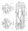
- FIG. 2 is a side cross-sectional view of an embodiment of a junction of a catheter body and an intermediate section, taken along a diameter.
- FIG 2B is a longitudinal cross sectional view of an alternate embodiment of the intermediate section.
- FIG. 3 is a side cross-sectional view of an embodiment of a distal section, taken along a diameter.
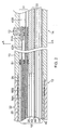
- FIG. 4 is a side cross-sectional view of an embodiment of a control handle with thumb controls in an engaged configuration.
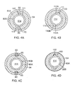
- FIG. 4A is a longitudinal cross-sectional view of the control handle of FIG. 4 , taken along line A--A, showing thumb controls in an engaged configuration.
- FIG. 4C is a longitudinal cross-sectional view of the control handle of FIG. 4 , taken along line C--C.
- FIG. 4D is a longitudinal cross-sectional view of the control handle of FIG. 4 , taken along line D--D.
- FIG. 5 is a side cross-sectional view of an embodiment of a control handle with thumb controls in a disengaged configuration.
- FIG. 6 is a side cross-sectional view of an embodiment of a control handle with thumb controls in another engaged configuration.
- FIGS. 7A-F illustrate various deflections resulting from selective engagement and manipulation of the thumb controls.
- the present invention is directed to a catheter 10 with a catheter body 12, an intermediate deflectable section 14 and a distal end section 15, including a tip electrode 17.
- a control handle 16 with a plurality of thumb controls, for example, 19a and 19b, manipulated by a user to accomplish a variety of independent and combined deflections of the intermediate section 14.
- the thumb controls can be disengaged for independent manipulation to provide independent deflection of a selected portion of the intermediate section, or releasably engaged in different configurations for joint manipulation to provide different selected combined deflections of the intermediate section.
- the single lumen 18 permits the components passing therethrough to float freely within the catheter body. If such components were restricted within multiple lumens, they can build up energy when the handle 16 is rotated, resulting in the catheter body 12 having a tendency to rotate back if, for example, the handle is released, or if bent around a curve, to flip over, either for which are undesirable performance characteristics.
- the outer diameter of the catheter body 12 is not critical, but is preferably no more than about 8 French. Likewise the thickness of the outer wall 22 is not critical.
- the inner surface of the outer wall 22 is lined with a stiffening tube 20, which can be made of any suitable material, e.g., polyimide.
- the stiffening tube 20 is held in place relative to the outer wall 22 at the proximal end of the catheter body 12.
- a first glue joint (not shown) is made between the distal ends of the stiffening tube 20 and the outer wall 22 by a fast drying glue, e.g. Super Glue.RTM.
- a second glue joint 26 is formed between the proximal ends of the stiffening tube 20 and outer wall 22 using a slower drying but stronger glue, e.g., polyurethane.
- the stiffening tube along with the braided outer wall 22, provides improved torsional stability while at the same time minimizing the wall thickness of the catheter, thus maximizing the diameter of the single lumen.
- the outer diameter of the stiffening tube 20 is about the same as or slightly smaller than the inner diameter of the outer wall 22.
- Polyimide tubing is suitable because it may be very thin walled while still providing very good stiffness. This maximizes the diameter of the central lumen 18 without sacrificing strength and stiffness. Polyimide material is typically not used for stiffening tubes because of its tendency to kink when bent.
- the outer wall 22 has an outer diameter of about 2.34 mm (0.092 inch) and an inner diameter of about 1.60 mm (0.063 inch) and the polyimide stiffening tube 20 has an outer diameter of about 1.56 mm (0.0615 inch) and an inner diameter of about 1.32 mm (0.052 inch).
- the intermediate section 14 comprises a shorter section of tubing 19 with multiple off-axis lumens, for example, first, second, third and fourth lumens 30, 31, 32 and 33.
- the tubing 19 is made of a suitable non-toxic material which is preferably more flexible than the catheter body 12.
- a suitable material for the tubing 19 is braided polyurethane, i.e., polyurethane with an embedded mesh of braided stainless steel or the like.
- the outer diameter of the intermediate section 14, like that of the catheter body 12, is preferably no greater than about 8 French. The size of the lumens is not critical.
- the intermediate section has an outer diameter of about 7 French 2.34 mm (0.092 inch) and the lumens are generally about the same size, having a diameter of about 0.56 mm (0.022 inch), or selected lumens can have a slightly larger diameter of about 0.91 mm (0.036 inch).
- FIG. 2 A means for attaching the catheter body 12 to the intermediate section 14 is illustrated in FIG. 2 .
- the proximal end of the intermediate section 14 comprises an inner counter bore 24 that receives the outer surface of the polyimide stiffener 20.
- the intermediate section 14 and catheter body 12 are attached by glue 29 or the like.
- the tip section 15 includes the tip electrode 17 which may be connected to the tubing 19 of the intermediate section 14 by means of a single lumen connector tubing 22.
- the connector tubing provides transition space for the various components extending from the tubing 22 to reorient themselves as needed for anchoring in the tip electrode 17.
- a distal surface of the tip electrode is provided with blind holes.
- blind hole 61 is provided to receive a distal end of the tip electrode lead wire 40
- blind hole 63 to receive a distal end of the thermocouple wires 43 and 44.
- Irrigation passage 66 is also formed in the tip electrode to receive a distal end of the irrigation tubing 35.
- the passage 66 is in communication with transverse branches 67 and fluid ports 69 allowing fluid delivered through the tubing 35 to pass to outside of the tip electrode.
- a blind hole 70 is also provided to receive a distal end of an electromagnetic position sensor.
- the electromagnetic sensor 72 is connected to an electromagnetic sensor cable 74, which extends through the fourth lumen 34 of the tip section 14 through the catheter body 12 into the control handle 16.
- the electromagnetic sensor cable 74 comprises multiple wires encased within a plastic sheath.
- the wires of the sensor-cable 74 are connected to a circuit board 64.
- the circuit board 64 amplifies the signal received from the electromagnetic sensor and transmits it to a computer in a form understandable by the computer.
- the circuit board contains an EPROM chip which shuts down the circuit board after the catheter has been used. This prevents the catheter, or at least the electromagnetic sensor, from being used twice.
- Suitable electromagnetic sensors for use in connection with the present invention are described, for example, in U.S. Pat. Nos. 5,391,199 and 6,201,387 , entitled “Miniaturized Position Sensor.”
- a preferred electromagnetic mapping sensor 72 is manufactured by Biosense Webster, Inc. and marketed under the trade designation NOGA.
- extending through the single lumen 18 of the catheter body 12 are various components, for example, lead wire 40 for the tip electrode, thermocouple wires 43 and 44, sensor cable 74, irrigation tubing 35 and multiple puller members 42, and any other wires or cables.
- Passing distally into first lumen 30 of the tubing 19 of the intermediate deflectable section is the irrigation tubing 35.
- Passing distally into fourth lumen 33 of the tubing are tip electrode lead wire 40, thermocouple wires 43, 44 and sensor cable 74.
- Passing distally into second lumen 31 are a first and shorter puller member 42A and a second and longer puller member 42B.
- longitudinal movement of the puller wire(s), relative to the catheter body 12 enables a user to deflect selected portion(s) of the intermediate section via the thumb controls 19a, 19b of the control handle.
- the distal ends of the deflection puller members 42 are anchored to the outer wall of the tubing 19 of the intermediate deflectable section by means of T-anchors 51.
- a distal anchor location of the distal end of the first and shorter puller member 42A (as represented by the location of T-anchor 51 A) is proximal of a distal anchor location of the distal end of the second and longer puller member (as represented by the location of T-anchor 51B).
- each puller member 42 extends through a plastic, e.g., Teflon.RTM., sheath (not shown), which prevents the puller members 42 from cutting into the wall of the tubing 19 of the intermediate section 14 when the intermediate section 14 is deflected.
- a plastic e.g., Teflon.RTM., sheath (not shown), which prevents the puller members 42 from cutting into the wall of the tubing 19 of the intermediate section 14 when the intermediate section 14 is deflected.
- each puller member has a respective compression coil 56 in surrounding relation therewith.
- the compression coils 56A, 56B are made of any suitable metal, e.g., stainless steel.
- the compression coils 56 are tightly wound on itself to provide flexibility, i.e., bending, but to resist compression.
- the inner diameter of the compression coils 56 is preferably slightly larger than the diameter of the puller wires 42. For example, when a puller member 42 has a diameter of about 0.178 mm (0.007 inches), the compression coil 56 preferably has an inner diameter of about 0.203 mm (0.008 inches).
- the Teflon.RTM. coating on the puller member 42 allows them to slide freely within the compression coils.
- the outer surface of the compression coils can be covered by a flexible, non-conductive sheath to prevent contact between the compression coils and other components, such as lead wires and cables, etc.
- the non-conductive sheath can be made of polyimide tubing.
- the compression coil 56A for the shorter puller member 42A extends from the proximal end of the catheter body 12 to the proximal end of the intermediate section 14, and the compression coil 56B for the longer puller member 56B extends from the proximal end of the catheter body 12 to at or near the distal anchor location of the shorter puller member 42A.
- the compression coils 56 are anchored at their proximal ends to the proximal end of the stiffening tube 20 in the catheter body 12 by a glue joint 50 (not shown) and at their distal ends near their respective distal anchor locations by glue joints 51 and 52 ( FIG. 2 ).
- the puller wires 42A, 42B and their respective compression coils 56A, 56B define in the intermediate section 14 a proximal portion 14A and a distal portion 14B, where the portions 14A, 14B can be independently deflected and simultaneously deflected.
- Each thumb control has an elongated proximal portion, for example a stem 80, and a wider distal portion, for example a conical or flared actuator 81.
- the thumb controls extend coaxially along a longitudinal axis of the piston, where the stem 80A of the proximal thumb control 19A is in a surrounding circumferential relationship with the stem 80B of the distal thumb control 19B.
- Each actuator 81 provides a user interface surface by which a user can move each thumb control longitudinally relative to the piston 54 and/or to each other by pushing or pulling on the neck with the user's thumb.
- stops 83 extend inwardly from an outer wall of the piston 54 at a predetermined location.
- the stops are received in diametrically opposing slots 85 that extend longitudinally along an outer surface of the stem 80A.
- the slots 85 having a width (transverse to the longitudinal axis of the control handle) that closely matches that of the stops 83 also minimize rotational movement of the stem 80A about its longitudinal axis relative to the piston 54. Accordingly, the proximal thumb control 19A is allowed longitudinal movement only relative to the piston 54 of a maximum distance that is determined by and generally equal to the distance between the stop 83 and an inner surface abutment 95.
- Anchored to a proximal end of the stem 80A is a proximal end of the puller wire which is wrapped around a pulley 87A positioned proximal of the inner surface abutment 95.
- the puller wire 42A anchored to the stem 80A is drawn distally to accomplish deflection along that puller wire distal of the compression coil 56A surrounding it.
- the stem 80A of the proximal thumb control 19A is formed with diametrically opposing slots 100 that extend longitudinally along its outer surface.
- the slots 100 have a width that is at least about twice the width of longitudinally elongated raised formations or guides 102 formed on an outer surface of the stem 80B of the distal thumb control 19B.
- the length of the slots 100 limits the maximum distance of longitudinal movement of the distal thumb control 19B relative to the proximal thumb control 19A.
- the distal thumb control 19B is allowed longitudinal movement along with a predetermined amount of rotational movement relative to the proximal thumb control 19A between two positions, the significance of the latter of which is explained further below.
- Anchored to a proximal end of the stem 80B is a proximal end of the puller wire 42B which is wrapped around a pulley 87B positioned proximal of the inner surface abutment 95.
- releasably locking members e.g., longitudinal rows of teeth 110A, 110B
- inner surface of the stem 80A has a greater number of teeth and outer surface of the stem 80B has a lesser number of teeth and a longitudinal channel 111 is formed extending immediately adjacent and parallel to the row of the teeth 110A on the inner surface of the stem 80A of the proximal thumb control 19A.
- the channel has a width that is at least the width of the teeth so that the teeth of the stem 80B of the distal proximal thumb control 19B can be rotated out of engagement (for example, out of longitudinal alignment) with the teeth of the stem 80A of the proximal thumb control 19A so that the thumb controls can be longitudinally moved and adjusted independently of each other.
- rotation of the inner thumb control in a clockwise direction disengages the respective teeth of the inner and outer thumb controls ( FIG. 4B ) and rotation in a counterclockwise direction engages the thumb controls so they can be moved as a single unit ( FIG. 4A ).
- engagement of the teeth in different selective configurations advantageously provides different deflections or deflection combinations of the deflectable intermediate section.
- each puller wire can be independently controlled by manipulation of each thumb control ( FIG. 5 ) from a neutral, undeflected configuration ( FIG. 7A ).
- FIG. 7B illustrates independent deflection of the distal portion 14B of the intermediate section by means of independent distal longitudinal movement of the thumb control 19B that operates the longer puller wire.
- FIG. 7C illustrates independent deflection of the proximal portion 14A of the intermediate section by means of independent distal longitudinal movement of the thumb control 19A that operates the shorter puller wire.
- each puller wire can be simultaneously deflected by manipulation of any thumb control ( FIG. 4 ).
- the intermediate deflectable section is able to adopt a more uniform curve profile comparable to conventional catheters ( FIG. 7D ).
- FIG. 7E illustrates a pre-deflection of the distal portion (broken lines) followed by deflection of both distal and proximal portions accomplished through coupled thumb controls (solid lines).
- FIG. 7F illustrates a pre-deflection of the proximal portion (broken lines) followed by deflection of both distal and proximal portions accomplished through coupled thumb controls (solid lines).
- These and other combined deflections can be achieved by selective distal anchoring positions of the puller wires, selective engagement and operation of the thumb controls.
- the catheter of the disclosed embodiment can be pre-deflected by selective engagement of the thumb controls in terms of the thumb controls longitudinal position relative to each other when the inner thumb control is rotated counterclockwise to lock with the outer thumb control.
- the pre-deflection can then be further increased or tightened by actuation of the coupled thumb control.
- operation of the thumb controls can be in any order as desired or appropriate, that is, deflection of the catheter as a whole can occur before or after deflection of various sections and/or pre-deflection of various sections.
- Visual and/or tactile indicia or markers can be provided on the actuators 81 of the thumb controls 19 to indicate alignment and/or nonalignment and hence engagement or disengagement of the releasable locking members between the thumb controls.
- the stem 80B of the inner thumb control 19B is hollow with a passage 114 to allow components such as the puller wires, lead wires, irrigation tubing, thermocouple wires and sensor cable to pass from the catheter body toward the proximal end of the control handle. These components pass into the control handle by means of a shrink sleeve 28 at the distal end of the inner thumb control 19B.
- the embodiment of the control handle of FIG. 4 includes a proximal piston 59.
- the irrigation tubing 35, the lead wires 40 and the electromagnetic sensor cable 74, thermocouple wires extend into the proximal piston.
- the electromagnetic sensor cable 74 connects to the circuit board 64.
- Wires 73 connect the circuit board 64 to a computer and imaging monitor (not shown).
- Guide tubes are provided in the control handle to allow longitudinal movement of these components as needed.
- the illustrated embodiment of FIG. 2 provides both puller wires 42A and 42B extending through a single lumen.
- deflection of the proximal portion 14A and the distal portion 14B are intended to be toward the same general direction and in a single plane.
- the puller wires can extend through adjacent lumens, such as illustrated in FIG. 2B , for deflection of the proximal portion 14A and the distal portion 14B in offset planes, where the degree of offset depends on the offset degree of the respective lumens. In the illustrated embodiment of FIG. 2B , the offset degree is about 90 degrees.
- the present invention is not limited to two thumb controls and two puller wires. It is understood that any number of thumb controls and a common number of puller wires falls within the scope of the present invention as the control handle can readily accommodate a greater number of nested thumb controls as appropriate or desired.
Landscapes
- Health & Medical Sciences (AREA)
- Life Sciences & Earth Sciences (AREA)
- Engineering & Computer Science (AREA)
- Hematology (AREA)
- General Health & Medical Sciences (AREA)
- Anesthesiology (AREA)
- Biomedical Technology (AREA)
- Heart & Thoracic Surgery (AREA)
- Biophysics (AREA)
- Animal Behavior & Ethology (AREA)
- Pulmonology (AREA)
- Public Health (AREA)
- Veterinary Medicine (AREA)
- Mechanical Engineering (AREA)
- Media Introduction/Drainage Providing Device (AREA)
- Electrotherapy Devices (AREA)
- Surgical Instruments (AREA)
Claims (18)
- Katheter (10), umfassend:einen langgestreckten Katheterkörper (12),einen ablenkbaren Zwischenabschnitt (14), der zumindest einen ersten Abschnitt und einen zweiten Abschnitt aufweist;einen Steuerhandgriff (16) proximal zu dem langgestreckten Körper (12), wobei der Steuerhandgriff (16) zumindest eine erste und eine zweite Daumensteuerung (19a, 19b) aufweist, wobei die erste Daumensteuerung mit einem Zugdraht (42A, 42B) verbunden ist, der sich durch den ersten Abschnitt erstreckt, undwobei die zweite Daumensteuerung mit einem zweiten Zugdraht (42A, 42B) verbunden ist, der sich durch den zweiten Abschnitt erstreckt,dadurch gekennzeichnet, dass die ersten und zweiten Daumensteuerungen (19a, 19b) lösbare Eingriffselemente (110A, 110B) aufweisen, die zwischen einer nicht in Eingriff stehenden Konfiguration und einer Eingriffskonfiguration bewegt werden können, worin die nicht in Eingriff stehende Konfiguration eine unabhängige Längsbewegung der Daumensteuerungen (19a, 19b) relativ zueinander gestattet und die Eingriffskonfiguration die Daumensteuerungen (19a, 19b) für eine Längsbewegung als einzelne Einheit relativ zu dem Steuerhandgriff (16) verbindet.
- Katheter nach Anspruch 1, worin sich die ersten und zweiten Daumensteuerungen in einer ineinander geschachtelten Konfiguration befinden.
- Katheter nach Anspruch 1 oder Anspruch 2, worin die lösbaren Eingriffselemente Zähne aufweisen, die auf Schnittstellenflächen der ersten und zweiten Daumensteuerungen geformt sind.
- Katheter nach einem der vorhergehenden Ansprüche, worin der Steuerhandgriff einen Kolben und mindestens einen Anschlag aufweist, worin der Anschlag die Längsbewegung der ersten Daumensteuerung relativ zu dem Kolben führt und eine Drehbewegung der ersten Daumensteuerung relativ zu dem Kolben minimiert.
- Katheter nach einem der vorhergehenden Ansprüche, worin die ersten und zweiten Daumensteuerungen für eine Längsbewegung relativ zueinander ausgelegt sind.
- Katheter nach einem der vorhergehenden Ansprüche, worin die ersten und zweiten Daumensteuerungen für eine Drehbewegung relativ zueinander zwischen zwei Stellungen ausgelegt sind.
- Katheter nach einem der vorhergehenden Ansprüche, ferner einen längeren Zugdraht und einen kürzeren Zugdraht umfassend.
- Katheter nach Anspruch 7, worin der längere Zugdraht eine erste distale Ankerstelle aufweist und der kürzere Zugdraht eine zweite distale Ankerstelle aufweist, und worin eine distale Ankerstelle weiter distal von dem Steuerhandgriff liegt als die andere distale Ankerstelle.
- Katheter nach Anspruch 8, ferner umfassend:eine kürzere Kompressionsspirale in umgebender Beziehung mit dem kürzeren Zugdraht, wobei die kürzere Kompressionsspirale ein distales Ende an einem oder in der Nähe eines proximalen Endes des ablenkbaren Zwischenabschnitts aufweist;eine längere Kompressionsspirale in umgebender Beziehung mit dem längeren Zugdraht, wobei die längere Kompressionsspirale ein distales Ende an dem oder in der Nähe des kürzeren Zugdrahts aufweist.
- Katheter nach einem der Ansprüche 7 bis 9, worin der ablenkbare Zwischenabschnitt zumindest einen distalen ablenkbaren Abschnitt und einen proximalen ablenkbaren Abschnitt aufweist;
worin eine der ersten und zweiten Daumensteuerungen eine äußere Daumensteuerung und die andere eine innere Daumensteuerung ist;
worin ein längerer Zugdraht ein proximales Ende, das in der inneren Daumensteuerung verankert ist, und ein distales Ende aufweist, das an dem oder in der Nähe des distalen Endes des distalen ablenkbaren Abschnitts angeordnet ist;
worin der kürzere Zugdraht ein proximales Ende, das in der äußeren Daumensteuerung verankert ist, und ein distales Ende aufweist, das an dem oder in der Nähe des distalen Endes des proximalen ablenkbaren Abschnitts verankert ist. - Katheter nach Anspruch 10, worin die lösbaren Eingriffselemente Zähne aufweisen, die auf Schnittstellenflächen der inneren und äußeren Daumensteuerungen geformt sind.
- Katheter nach Anspruch 10 oder Anspruch 11, worin der Steuerhandgriff einen Kolben und mindestens einen Anschlag aufweist, worin der Anschlag die Längsbewegung der ersten Daumensteuerung relativ zu dem Kolben führt und eine Drehbewegung der ersten Daumensteuerung relativ zu dem Kolben minimiert.
- Katheter nach einem der Ansprüche 10 bis 12, worin zumindest eine Führung auf einer Schnittstelle zwischen der inneren und äußeren Daumensteuerung zur Führung der Längsbewegung der Daumensteuerungen relativ zueinander bereitgestellt ist.
- Katheter nach Anspruch 13, worin mindestens ein Schlitz, der die eine Führung aufnimmt, auf einer anderen Schnittstelle zwischen der inneren und äußeren Daumensteuerung zur Bereitstellung der Drehbewegung der Daumensteuerungen relativ zueinander bereitgestellt ist.
- Katheter nach einem der vorhergehenden Ansprüche, worin jede Daumensteuerung einen Schaftabschnitt und einen Halsabschnitt aufweist, worin ein Schaftabschnitt in einer Außenumfangsbeziehung mit dem anderen Schaftabschnitt steht.
- Katheter nach Anspruch 15, in Abhängigkeit von einem der Ansprüche 1 bis 9, worin ein erster Satz von lösbaren Eingriffselementen auf einer Innenseite des Schaftabschnitts der ersten Daumensteuerung geformt ist und ein zweiter Satz von lösbaren Eingriffselementen auf einer Außenseite des Schaftabschnitts der zweiten Daumensteuerung geformt ist.
- Katheter nach Anspruch 15, in Abhängigkeit von einem der Ansprüche 10 bis 14, worin ein erster Satz von lösbaren Eingriffselementen auf einer Innenseite des Schaftabschnitts der äußeren Daumensteuerung geformt ist und ein zweiter Satz von lösbaren Eingriffselementen auf einer Außenseite des Schaftabschnitts der inneren Daumensteuerung geformt ist.
- Katheter nach Anspruch 16 oder Anspruch 17, worin der erste Satz und der zweite Satz von lösbaren Eingriffselementen durch Drehung einer Daumensteuerung relativ zu der anderen Daumensteuerung in Eingriff gebracht werden.
Applications Claiming Priority (1)
| Application Number | Priority Date | Filing Date | Title |
|---|---|---|---|
| US13/029,056 US8430864B2 (en) | 2011-02-16 | 2011-02-16 | Catheter with multiple deflections |
Publications (2)
| Publication Number | Publication Date |
|---|---|
| EP2489395A1 EP2489395A1 (de) | 2012-08-22 |
| EP2489395B1 true EP2489395B1 (de) | 2014-10-22 |
Family
ID=45655868
Family Applications (1)
| Application Number | Title | Priority Date | Filing Date |
|---|---|---|---|
| EP12155638.5A Active EP2489395B1 (de) | 2011-02-16 | 2012-02-15 | Katheter mit mehreren Ablenkungen |
Country Status (7)
| Country | Link |
|---|---|
| US (1) | US8430864B2 (de) |
| EP (1) | EP2489395B1 (de) |
| JP (1) | JP5936872B2 (de) |
| CN (1) | CN102670300B (de) |
| AU (1) | AU2012200792B2 (de) |
| CA (1) | CA2768270C (de) |
| IL (1) | IL218000A (de) |
Families Citing this family (30)
| Publication number | Priority date | Publication date | Assignee | Title |
|---|---|---|---|---|
| DK2107920T3 (da) | 2007-01-29 | 2013-10-21 | Univ Fraser Simon | Transvaskulært nervestimulationsapparat |
| WO2013016275A1 (en) | 2011-07-22 | 2013-01-31 | Cook Medical Technologies Llc | Irrigation devices adapted to be used with a light source for the identification and treatment of bodily passages |
| AU2013230648B2 (en) | 2012-03-05 | 2017-06-15 | Lungpacer Medical Inc. | Transvascular nerve stimulation apparatus and methods |
| BR112014032002A2 (pt) | 2012-06-21 | 2017-06-27 | Univ Fraser Simon | sistemas de estimulação de diafragma transvascular e métodos de utilização |
| JP6200140B2 (ja) * | 2012-09-24 | 2017-09-20 | 日本ライフライン株式会社 | 電極カテーテル |
| WO2014134257A1 (en) | 2013-02-28 | 2014-09-04 | Cook Medical Technologies Llc | Medical devices, systems, and methods for the visualization and treatment of bodily passages |
| US9375550B2 (en) | 2013-03-15 | 2016-06-28 | St. Jude Medical, Atrial Fibrillation Division, Inc. | Catheter actuators providing mechanical advantage |
| US9549748B2 (en) | 2013-08-01 | 2017-01-24 | Cook Medical Technologies Llc | Methods of locating and treating tissue in a wall defining a bodily passage |
| NL2011364C2 (en) * | 2013-08-30 | 2015-03-03 | Univ Delft Tech | Catheter for use in endovascular intervention. |
| EP3013403B1 (de) | 2013-09-30 | 2019-08-07 | St. Jude Medical, Cardiology Division, Inc. | Katheter mit einem aktiven begradigungsmechanismus |
| US9839765B2 (en) | 2013-11-12 | 2017-12-12 | St. Jude Medical, Cardiology Division, Inc. | Transfemoral mitral valve repair delivery device |
| CA2930809A1 (en) | 2013-11-22 | 2015-05-28 | Simon Fraser University | Apparatus and methods for assisted breathing by transvascular nerve stimulation |
| EP3824949B1 (de) | 2014-01-21 | 2023-12-20 | Lungpacer Medical Inc. | Systeme zur optimierung der multi-elektroden-nervenstimulation |
| US9937323B2 (en) | 2014-02-28 | 2018-04-10 | Cook Medical Technologies Llc | Deflectable catheters, systems, and methods for the visualization and treatment of bodily passages |
| US20170197060A1 (en) | 2014-06-17 | 2017-07-13 | St. Jude Medical, Cardiology Division, Inc. | Asymmetric catheter curve shapes |
| US10195398B2 (en) | 2014-08-13 | 2019-02-05 | Cook Medical Technologies Llc | Tension member seal and securing mechanism for medical devices |
| CN109561901B (zh) * | 2016-05-23 | 2022-02-25 | 马可外科公司 | 用于切割骨的医疗装置 |
| JP6712355B2 (ja) * | 2016-07-28 | 2020-06-17 | クック・メディカル・テクノロジーズ・リミテッド・ライアビリティ・カンパニーCook Medical Technologies Llc | 操縦可能なカテーテルにおける遠位側ワイヤ固定 |
| US10293164B2 (en) | 2017-05-26 | 2019-05-21 | Lungpacer Medical Inc. | Apparatus and methods for assisted breathing by transvascular nerve stimulation |
| US12029901B2 (en) | 2017-06-30 | 2024-07-09 | Lungpacer Medical Inc. | Devices and methods for prevention, moderation, and/or treatment of cognitive injury |
| US10195429B1 (en) | 2017-08-02 | 2019-02-05 | Lungpacer Medical Inc. | Systems and methods for intravascular catheter positioning and/or nerve stimulation |
| US10940308B2 (en) | 2017-08-04 | 2021-03-09 | Lungpacer Medical Inc. | Systems and methods for trans-esophageal sympathetic ganglion recruitment |
| KR102108841B1 (ko) * | 2017-10-26 | 2020-05-11 | 쥬베뉴 주식회사 | 의료기구 |
| US20190175908A1 (en) | 2017-12-11 | 2019-06-13 | Lungpacer Medical Inc. | Systems and methods for strengthening a respiratory muscle |
| US11918762B2 (en) | 2018-10-03 | 2024-03-05 | St. Jude Medical, Cardiology Division, Inc. | Reduced actuation force electrophysiology catheter handle |
| CN111110985B (zh) * | 2018-10-31 | 2025-04-15 | 杭州唯强医疗科技有限公司 | 调弯手柄及可调弯导管 |
| WO2020097331A1 (en) | 2018-11-08 | 2020-05-14 | Lungpacer Medical Inc. | Stimulation systems and related user interfaces |
| WO2020232333A1 (en) | 2019-05-16 | 2020-11-19 | Lungpacer Medical Inc. | Systems and methods for sensing and stimulation |
| EP3983057B1 (de) | 2019-06-12 | 2026-04-08 | Lungpacer Medical Inc. | Schaltung für medizinische stimulationssysteme |
| EP4124309B1 (de) | 2021-07-29 | 2025-04-30 | Merit Medical Systems, Inc. | Medizinische vorrichtungen mit einer auslöseranordnung für einen drehbaren katheter |
Family Cites Families (32)
| Publication number | Priority date | Publication date | Assignee | Title |
|---|---|---|---|---|
| SE325986B (de) | 1965-07-05 | 1970-07-13 | T Almen | |
| US4976688A (en) * | 1989-02-03 | 1990-12-11 | Rosenblum Jeffrey L | Position-adjustable thoracic catheter |
| US6413234B1 (en) | 1990-02-02 | 2002-07-02 | Ep Technologies, Inc. | Assemblies for creating compound curves in distal catheter regions |
| US5891088A (en) | 1990-02-02 | 1999-04-06 | Ep Technologies, Inc. | Catheter steering assembly providing asymmetric left and right curve configurations |
| US5325845A (en) * | 1992-06-08 | 1994-07-05 | Adair Edwin Lloyd | Steerable sheath for use with selected removable optical catheter |
| US5334145A (en) * | 1992-09-16 | 1994-08-02 | Lundquist Ingemar H | Torquable catheter |
| US5441483A (en) * | 1992-11-16 | 1995-08-15 | Avitall; Boaz | Catheter deflection control |
| US5391199A (en) | 1993-07-20 | 1995-02-21 | Biosense, Inc. | Apparatus and method for treating cardiac arrhythmias |
| US5487757A (en) * | 1993-07-20 | 1996-01-30 | Medtronic Cardiorhythm | Multicurve deflectable catheter |
| US5882333A (en) * | 1994-05-13 | 1999-03-16 | Cardima, Inc. | Catheter with deflectable distal section |
| US5656030A (en) * | 1995-05-22 | 1997-08-12 | Boston Scientific Corporation | Bidirectional steerable catheter with deflectable distal tip |
| US5853368A (en) * | 1996-12-23 | 1998-12-29 | Hewlett-Packard Company | Ultrasound imaging catheter having an independently-controllable treatment structure |
| US6464645B1 (en) * | 1997-01-31 | 2002-10-15 | Acuson Corporation | Ultrasonic transducer assembly controller |
| US5938616A (en) * | 1997-01-31 | 1999-08-17 | Acuson Corporation | Steering mechanism and steering line for a catheter-mounted ultrasonic transducer |
| US6123699A (en) * | 1997-09-05 | 2000-09-26 | Cordis Webster, Inc. | Omni-directional steerable catheter |
| US6201387B1 (en) | 1997-10-07 | 2001-03-13 | Biosense, Inc. | Miniaturized position sensor having photolithographic coils for tracking a medical probe |
| US6198974B1 (en) | 1998-08-14 | 2001-03-06 | Cordis Webster, Inc. | Bi-directional steerable catheter |
| US6795721B2 (en) | 2000-01-27 | 2004-09-21 | Biosense Webster, Inc. | Bidirectional catheter having mapping assembly |
| US6926669B1 (en) * | 2000-10-10 | 2005-08-09 | Medtronic, Inc. | Heart wall ablation/mapping catheter and method |
| US6610058B2 (en) | 2001-05-02 | 2003-08-26 | Cardiac Pacemakers, Inc. | Dual-profile steerable catheter |
| US6913594B2 (en) | 2001-12-31 | 2005-07-05 | Biosense Webster, Inc. | Dual-function catheter handle |
| US8298161B2 (en) * | 2002-09-12 | 2012-10-30 | Intuitive Surgical Operations, Inc. | Shape-transferring cannula system and method of use |
| US7402141B2 (en) | 2003-08-27 | 2008-07-22 | Heuser Richard R | Catheter guidewire system using concentric wires |
| US7077823B2 (en) | 2003-11-19 | 2006-07-18 | Biosense Webster, Inc. | Bidirectional steerable catheter with slidable mated puller wires |
| US20060149129A1 (en) | 2005-01-05 | 2006-07-06 | Watts H D | Catheter with multiple visual elements |
| US7465288B2 (en) * | 2005-06-28 | 2008-12-16 | St. Jude Medical, Atrial Fibrillation Division, Inc. | Actuation handle for a catheter |
| US9833595B2 (en) * | 2005-12-30 | 2017-12-05 | Biosense Webster, Inc. | Dual-lever bi-directional handle |
| JP4912705B2 (ja) * | 2006-03-17 | 2012-04-11 | 日本コヴィディエン株式会社 | 医療用チューブ組立体 |
| US8591460B2 (en) | 2008-06-13 | 2013-11-26 | Cardiosolutions, Inc. | Steerable catheter and dilator and system and method for implanting a heart implant |
| US8048025B2 (en) | 2008-07-07 | 2011-11-01 | Boston Scientific Scimed, Inc. | Multi-plane motion control mechanism |
| US8137308B2 (en) * | 2008-09-16 | 2012-03-20 | Biosense Webster, Inc. | Catheter with adjustable deflection sensitivity |
| US9254372B2 (en) * | 2010-08-13 | 2016-02-09 | Cathrx Ltd | Catheter assembly with deflection size adjustability |
-
2011
- 2011-02-16 US US13/029,056 patent/US8430864B2/en active Active
-
2012
- 2012-02-09 IL IL218000A patent/IL218000A/en active IP Right Grant
- 2012-02-10 AU AU2012200792A patent/AU2012200792B2/en not_active Ceased
- 2012-02-14 CA CA2768270A patent/CA2768270C/en not_active Expired - Fee Related
- 2012-02-15 JP JP2012030303A patent/JP5936872B2/ja active Active
- 2012-02-15 EP EP12155638.5A patent/EP2489395B1/de active Active
- 2012-02-16 CN CN201210045985.0A patent/CN102670300B/zh active Active
Also Published As
| Publication number | Publication date |
|---|---|
| CN102670300A (zh) | 2012-09-19 |
| US20120209143A1 (en) | 2012-08-16 |
| EP2489395A1 (de) | 2012-08-22 |
| CA2768270A1 (en) | 2012-08-16 |
| CA2768270C (en) | 2019-04-23 |
| JP5936872B2 (ja) | 2016-06-22 |
| JP2012166031A (ja) | 2012-09-06 |
| AU2012200792B2 (en) | 2015-07-02 |
| US8430864B2 (en) | 2013-04-30 |
| AU2012200792A1 (en) | 2012-08-30 |
| CN102670300B (zh) | 2015-12-02 |
| IL218000A (en) | 2015-11-30 |
| IL218000A0 (en) | 2012-03-29 |
Similar Documents
| Publication | Publication Date | Title |
|---|---|---|
| EP2489395B1 (de) | Katheter mit mehreren Ablenkungen | |
| US20260090835A1 (en) | Double loop lasso with single puller wire for bi-directional actuation | |
| US11617861B2 (en) | Triple coil catheter support | |
| US11744995B2 (en) | Unidirectional catheter control handle with tensioning control | |
| US6198974B1 (en) | Bi-directional steerable catheter | |
| US6171277B1 (en) | Bi-directional control handle for steerable catheter | |
| AU2012268844B2 (en) | Medical device control handle with multiple puller wires | |
| JP2002512534A (ja) | カテーテル撓み制御 | |
| AU2017210548B2 (en) | Medical device control handle with multiple puller wires |
Legal Events
| Date | Code | Title | Description |
|---|---|---|---|
| PUAI | Public reference made under article 153(3) epc to a published international application that has entered the european phase |
Free format text: ORIGINAL CODE: 0009012 |
|
| AK | Designated contracting states |
Kind code of ref document: A1 Designated state(s): AL AT BE BG CH CY CZ DE DK EE ES FI FR GB GR HR HU IE IS IT LI LT LU LV MC MK MT NL NO PL PT RO RS SE SI SK SM TR |
|
| AX | Request for extension of the european patent |
Extension state: BA ME |
|
| 17P | Request for examination filed |
Effective date: 20130220 |
|
| GRAP | Despatch of communication of intention to grant a patent |
Free format text: ORIGINAL CODE: EPIDOSNIGR1 |
|
| INTG | Intention to grant announced |
Effective date: 20140514 |
|
| GRAS | Grant fee paid |
Free format text: ORIGINAL CODE: EPIDOSNIGR3 |
|
| GRAA | (expected) grant |
Free format text: ORIGINAL CODE: 0009210 |
|
| AK | Designated contracting states |
Kind code of ref document: B1 Designated state(s): AL AT BE BG CH CY CZ DE DK EE ES FI FR GB GR HR HU IE IS IT LI LT LU LV MC MK MT NL NO PL PT RO RS SE SI SK SM TR |
|
| REG | Reference to a national code |
Ref country code: GB Ref legal event code: FG4D |
|
| REG | Reference to a national code |
Ref country code: CH Ref legal event code: EP |
|
| REG | Reference to a national code |
Ref country code: AT Ref legal event code: REF Ref document number: 692308 Country of ref document: AT Kind code of ref document: T Effective date: 20141115 |
|
| REG | Reference to a national code |
Ref country code: IE Ref legal event code: FG4D |
|
| REG | Reference to a national code |
Ref country code: DE Ref legal event code: R096 Ref document number: 602012003446 Country of ref document: DE Effective date: 20141204 |
|
| REG | Reference to a national code |
Ref country code: NL Ref legal event code: T3 |
|
| REG | Reference to a national code |
Ref country code: AT Ref legal event code: MK05 Ref document number: 692308 Country of ref document: AT Kind code of ref document: T Effective date: 20141022 |
|
| REG | Reference to a national code |
Ref country code: LT Ref legal event code: MG4D |
|
| PG25 | Lapsed in a contracting state [announced via postgrant information from national office to epo] |
Ref country code: LT Free format text: LAPSE BECAUSE OF FAILURE TO SUBMIT A TRANSLATION OF THE DESCRIPTION OR TO PAY THE FEE WITHIN THE PRESCRIBED TIME-LIMIT Effective date: 20141022 Ref country code: PT Free format text: LAPSE BECAUSE OF FAILURE TO SUBMIT A TRANSLATION OF THE DESCRIPTION OR TO PAY THE FEE WITHIN THE PRESCRIBED TIME-LIMIT Effective date: 20150223 Ref country code: NO Free format text: LAPSE BECAUSE OF FAILURE TO SUBMIT A TRANSLATION OF THE DESCRIPTION OR TO PAY THE FEE WITHIN THE PRESCRIBED TIME-LIMIT Effective date: 20150122 Ref country code: IS Free format text: LAPSE BECAUSE OF FAILURE TO SUBMIT A TRANSLATION OF THE DESCRIPTION OR TO PAY THE FEE WITHIN THE PRESCRIBED TIME-LIMIT Effective date: 20150222 Ref country code: FI Free format text: LAPSE BECAUSE OF FAILURE TO SUBMIT A TRANSLATION OF THE DESCRIPTION OR TO PAY THE FEE WITHIN THE PRESCRIBED TIME-LIMIT Effective date: 20141022 Ref country code: ES Free format text: LAPSE BECAUSE OF FAILURE TO SUBMIT A TRANSLATION OF THE DESCRIPTION OR TO PAY THE FEE WITHIN THE PRESCRIBED TIME-LIMIT Effective date: 20141022 |
|
| PG25 | Lapsed in a contracting state [announced via postgrant information from national office to epo] |
Ref country code: AT Free format text: LAPSE BECAUSE OF FAILURE TO SUBMIT A TRANSLATION OF THE DESCRIPTION OR TO PAY THE FEE WITHIN THE PRESCRIBED TIME-LIMIT Effective date: 20141022 Ref country code: GR Free format text: LAPSE BECAUSE OF FAILURE TO SUBMIT A TRANSLATION OF THE DESCRIPTION OR TO PAY THE FEE WITHIN THE PRESCRIBED TIME-LIMIT Effective date: 20150123 Ref country code: CY Free format text: LAPSE BECAUSE OF FAILURE TO SUBMIT A TRANSLATION OF THE DESCRIPTION OR TO PAY THE FEE WITHIN THE PRESCRIBED TIME-LIMIT Effective date: 20141022 Ref country code: HR Free format text: LAPSE BECAUSE OF FAILURE TO SUBMIT A TRANSLATION OF THE DESCRIPTION OR TO PAY THE FEE WITHIN THE PRESCRIBED TIME-LIMIT Effective date: 20141022 Ref country code: RS Free format text: LAPSE BECAUSE OF FAILURE TO SUBMIT A TRANSLATION OF THE DESCRIPTION OR TO PAY THE FEE WITHIN THE PRESCRIBED TIME-LIMIT Effective date: 20141022 Ref country code: PL Free format text: LAPSE BECAUSE OF FAILURE TO SUBMIT A TRANSLATION OF THE DESCRIPTION OR TO PAY THE FEE WITHIN THE PRESCRIBED TIME-LIMIT Effective date: 20141022 Ref country code: LV Free format text: LAPSE BECAUSE OF FAILURE TO SUBMIT A TRANSLATION OF THE DESCRIPTION OR TO PAY THE FEE WITHIN THE PRESCRIBED TIME-LIMIT Effective date: 20141022 Ref country code: SE Free format text: LAPSE BECAUSE OF FAILURE TO SUBMIT A TRANSLATION OF THE DESCRIPTION OR TO PAY THE FEE WITHIN THE PRESCRIBED TIME-LIMIT Effective date: 20141022 |
|
| REG | Reference to a national code |
Ref country code: DE Ref legal event code: R097 Ref document number: 602012003446 Country of ref document: DE |
|
| PG25 | Lapsed in a contracting state [announced via postgrant information from national office to epo] |
Ref country code: SK Free format text: LAPSE BECAUSE OF FAILURE TO SUBMIT A TRANSLATION OF THE DESCRIPTION OR TO PAY THE FEE WITHIN THE PRESCRIBED TIME-LIMIT Effective date: 20141022 Ref country code: EE Free format text: LAPSE BECAUSE OF FAILURE TO SUBMIT A TRANSLATION OF THE DESCRIPTION OR TO PAY THE FEE WITHIN THE PRESCRIBED TIME-LIMIT Effective date: 20141022 Ref country code: DK Free format text: LAPSE BECAUSE OF FAILURE TO SUBMIT A TRANSLATION OF THE DESCRIPTION OR TO PAY THE FEE WITHIN THE PRESCRIBED TIME-LIMIT Effective date: 20141022 Ref country code: CZ Free format text: LAPSE BECAUSE OF FAILURE TO SUBMIT A TRANSLATION OF THE DESCRIPTION OR TO PAY THE FEE WITHIN THE PRESCRIBED TIME-LIMIT Effective date: 20141022 Ref country code: RO Free format text: LAPSE BECAUSE OF FAILURE TO SUBMIT A TRANSLATION OF THE DESCRIPTION OR TO PAY THE FEE WITHIN THE PRESCRIBED TIME-LIMIT Effective date: 20141022 |
|
| PLBE | No opposition filed within time limit |
Free format text: ORIGINAL CODE: 0009261 |
|
| STAA | Information on the status of an ep patent application or granted ep patent |
Free format text: STATUS: NO OPPOSITION FILED WITHIN TIME LIMIT |
|
| 26N | No opposition filed |
Effective date: 20150723 |
|
| PG25 | Lapsed in a contracting state [announced via postgrant information from national office to epo] |
Ref country code: LU Free format text: LAPSE BECAUSE OF FAILURE TO SUBMIT A TRANSLATION OF THE DESCRIPTION OR TO PAY THE FEE WITHIN THE PRESCRIBED TIME-LIMIT Effective date: 20150215 |
|
| REG | Reference to a national code |
Ref country code: CH Ref legal event code: PL |
|
| PG25 | Lapsed in a contracting state [announced via postgrant information from national office to epo] |
Ref country code: MC Free format text: LAPSE BECAUSE OF FAILURE TO SUBMIT A TRANSLATION OF THE DESCRIPTION OR TO PAY THE FEE WITHIN THE PRESCRIBED TIME-LIMIT Effective date: 20141022 Ref country code: CH Free format text: LAPSE BECAUSE OF NON-PAYMENT OF DUE FEES Effective date: 20150228 Ref country code: LI Free format text: LAPSE BECAUSE OF NON-PAYMENT OF DUE FEES Effective date: 20150228 |
|
| REG | Reference to a national code |
Ref country code: IE Ref legal event code: MM4A |
|
| REG | Reference to a national code |
Ref country code: FR Ref legal event code: PLFP Year of fee payment: 5 |
|
| PG25 | Lapsed in a contracting state [announced via postgrant information from national office to epo] |
Ref country code: IE Free format text: LAPSE BECAUSE OF NON-PAYMENT OF DUE FEES Effective date: 20150215 |
|
| PG25 | Lapsed in a contracting state [announced via postgrant information from national office to epo] |
Ref country code: SI Free format text: LAPSE BECAUSE OF FAILURE TO SUBMIT A TRANSLATION OF THE DESCRIPTION OR TO PAY THE FEE WITHIN THE PRESCRIBED TIME-LIMIT Effective date: 20141022 |
|
| PG25 | Lapsed in a contracting state [announced via postgrant information from national office to epo] |
Ref country code: MT Free format text: LAPSE BECAUSE OF FAILURE TO SUBMIT A TRANSLATION OF THE DESCRIPTION OR TO PAY THE FEE WITHIN THE PRESCRIBED TIME-LIMIT Effective date: 20141022 |
|
| REG | Reference to a national code |
Ref country code: FR Ref legal event code: PLFP Year of fee payment: 6 |
|
| PG25 | Lapsed in a contracting state [announced via postgrant information from national office to epo] |
Ref country code: BG Free format text: LAPSE BECAUSE OF FAILURE TO SUBMIT A TRANSLATION OF THE DESCRIPTION OR TO PAY THE FEE WITHIN THE PRESCRIBED TIME-LIMIT Effective date: 20141022 Ref country code: HU Free format text: LAPSE BECAUSE OF FAILURE TO SUBMIT A TRANSLATION OF THE DESCRIPTION OR TO PAY THE FEE WITHIN THE PRESCRIBED TIME-LIMIT; INVALID AB INITIO Effective date: 20120215 Ref country code: SM Free format text: LAPSE BECAUSE OF FAILURE TO SUBMIT A TRANSLATION OF THE DESCRIPTION OR TO PAY THE FEE WITHIN THE PRESCRIBED TIME-LIMIT Effective date: 20141022 |
|
| PG25 | Lapsed in a contracting state [announced via postgrant information from national office to epo] |
Ref country code: TR Free format text: LAPSE BECAUSE OF FAILURE TO SUBMIT A TRANSLATION OF THE DESCRIPTION OR TO PAY THE FEE WITHIN THE PRESCRIBED TIME-LIMIT Effective date: 20141022 |
|
| REG | Reference to a national code |
Ref country code: FR Ref legal event code: PLFP Year of fee payment: 7 |
|
| PG25 | Lapsed in a contracting state [announced via postgrant information from national office to epo] |
Ref country code: MK Free format text: LAPSE BECAUSE OF FAILURE TO SUBMIT A TRANSLATION OF THE DESCRIPTION OR TO PAY THE FEE WITHIN THE PRESCRIBED TIME-LIMIT Effective date: 20141022 |
|
| PG25 | Lapsed in a contracting state [announced via postgrant information from national office to epo] |
Ref country code: AL Free format text: LAPSE BECAUSE OF FAILURE TO SUBMIT A TRANSLATION OF THE DESCRIPTION OR TO PAY THE FEE WITHIN THE PRESCRIBED TIME-LIMIT Effective date: 20141022 |
|
| PGFP | Annual fee paid to national office [announced via postgrant information from national office to epo] |
Ref country code: BE Payment date: 20190116 Year of fee payment: 8 |
|
| REG | Reference to a national code |
Ref country code: BE Ref legal event code: MM Effective date: 20200229 |
|
| PG25 | Lapsed in a contracting state [announced via postgrant information from national office to epo] |
Ref country code: BE Free format text: LAPSE BECAUSE OF NON-PAYMENT OF DUE FEES Effective date: 20200229 |
|
| PGFP | Annual fee paid to national office [announced via postgrant information from national office to epo] |
Ref country code: NL Payment date: 20220118 Year of fee payment: 11 |
|
| REG | Reference to a national code |
Ref country code: NL Ref legal event code: MM Effective date: 20230301 |
|
| PG25 | Lapsed in a contracting state [announced via postgrant information from national office to epo] |
Ref country code: NL Free format text: LAPSE BECAUSE OF NON-PAYMENT OF DUE FEES Effective date: 20230301 |
|
| PGFP | Annual fee paid to national office [announced via postgrant information from national office to epo] |
Ref country code: FR Payment date: 20251231 Year of fee payment: 15 |
|
| PGFP | Annual fee paid to national office [announced via postgrant information from national office to epo] |
Ref country code: GB Payment date: 20260106 Year of fee payment: 15 |
|
| PGFP | Annual fee paid to national office [announced via postgrant information from national office to epo] |
Ref country code: DE Payment date: 20251230 Year of fee payment: 15 |
|
| PGFP | Annual fee paid to national office [announced via postgrant information from national office to epo] |
Ref country code: IT Payment date: 20260122 Year of fee payment: 15 |