EP2489841A1 - Cuve à huile dotée d'une ouverture de filtre à huile fixée sur celle-ci - Google Patents
Cuve à huile dotée d'une ouverture de filtre à huile fixée sur celle-ci Download PDFInfo
- Publication number
- EP2489841A1 EP2489841A1 EP12001747A EP12001747A EP2489841A1 EP 2489841 A1 EP2489841 A1 EP 2489841A1 EP 12001747 A EP12001747 A EP 12001747A EP 12001747 A EP12001747 A EP 12001747A EP 2489841 A1 EP2489841 A1 EP 2489841A1
- Authority
- EP
- European Patent Office
- Prior art keywords
- oil
- filter unit
- magnet holder
- oil pan
- filter
- Prior art date
- Legal status (The legal status is an assumption and is not a legal conclusion. Google has not performed a legal analysis and makes no representation as to the accuracy of the status listed.)
- Granted
Links
- 230000005540 biological transmission Effects 0.000 claims abstract description 19
- 239000000463 material Substances 0.000 claims abstract description 14
- 239000000696 magnetic material Substances 0.000 claims abstract description 13
- 238000001914 filtration Methods 0.000 claims abstract description 11
- 229910052782 aluminium Inorganic materials 0.000 claims abstract description 5
- XAGFODPZIPBFFR-UHFFFAOYSA-N aluminium Chemical compound [Al] XAGFODPZIPBFFR-UHFFFAOYSA-N 0.000 claims abstract description 5
- 239000000356 contaminant Substances 0.000 claims description 6
- 125000006850 spacer group Chemical group 0.000 claims description 4
- 239000003921 oil Substances 0.000 abstract description 115
- 239000010705 motor oil Substances 0.000 abstract description 3
- 239000012208 gear oil Substances 0.000 abstract description 2
- 239000012535 impurity Substances 0.000 abstract description 2
- 238000011161 development Methods 0.000 description 2
- 230000018109 developmental process Effects 0.000 description 2
- 239000000314 lubricant Substances 0.000 description 2
- 230000014759 maintenance of location Effects 0.000 description 2
- 239000007769 metal material Substances 0.000 description 2
- 238000005457 optimization Methods 0.000 description 2
- 239000002245 particle Substances 0.000 description 2
- 230000002093 peripheral effect Effects 0.000 description 2
- 238000007789 sealing Methods 0.000 description 2
- CWYNVVGOOAEACU-UHFFFAOYSA-N Fe2+ Chemical compound [Fe+2] CWYNVVGOOAEACU-UHFFFAOYSA-N 0.000 description 1
- 238000010276 construction Methods 0.000 description 1
- 230000001419 dependent effect Effects 0.000 description 1
- 230000009977 dual effect Effects 0.000 description 1
- 238000004519 manufacturing process Methods 0.000 description 1
- 238000011085 pressure filtration Methods 0.000 description 1
- 230000000717 retained effect Effects 0.000 description 1
- 238000005476 soldering Methods 0.000 description 1
- 239000007787 solid Substances 0.000 description 1
- 238000000967 suction filtration Methods 0.000 description 1
- 238000003466 welding Methods 0.000 description 1
Images


Classifications
-
- F—MECHANICAL ENGINEERING; LIGHTING; HEATING; WEAPONS; BLASTING
- F01—MACHINES OR ENGINES IN GENERAL; ENGINE PLANTS IN GENERAL; STEAM ENGINES
- F01M—LUBRICATING OF MACHINES OR ENGINES IN GENERAL; LUBRICATING INTERNAL COMBUSTION ENGINES; CRANKCASE VENTILATING
- F01M11/00—Component parts, details or accessories, not provided for in, or of interest apart from, groups F01M1/00 - F01M9/00
- F01M11/0004—Oilsumps
-
- F—MECHANICAL ENGINEERING; LIGHTING; HEATING; WEAPONS; BLASTING
- F01—MACHINES OR ENGINES IN GENERAL; ENGINE PLANTS IN GENERAL; STEAM ENGINES
- F01M—LUBRICATING OF MACHINES OR ENGINES IN GENERAL; LUBRICATING INTERNAL COMBUSTION ENGINES; CRANKCASE VENTILATING
- F01M11/00—Component parts, details or accessories, not provided for in, or of interest apart from, groups F01M1/00 - F01M9/00
- F01M11/0004—Oilsumps
- F01M2011/0029—Oilsumps with oil filters
-
- F—MECHANICAL ENGINEERING; LIGHTING; HEATING; WEAPONS; BLASTING
- F01—MACHINES OR ENGINES IN GENERAL; ENGINE PLANTS IN GENERAL; STEAM ENGINES
- F01M—LUBRICATING OF MACHINES OR ENGINES IN GENERAL; LUBRICATING INTERNAL COMBUSTION ENGINES; CRANKCASE VENTILATING
- F01M11/00—Component parts, details or accessories, not provided for in, or of interest apart from, groups F01M1/00 - F01M9/00
- F01M11/0004—Oilsumps
- F01M2011/007—Oil pickup tube to oil pump, e.g. strainer
Definitions
- the invention relates to an oil pan with an attached oil filter unit according to the preamble of claim 1.
- the oil sump in question is preferably an oil sump for engines and / or transmissions for motor vehicles, construction vehicles and the like. From the prior art, it is known to arrange on the inner surface of an oil pan a filter unit which serves to filter the engine and / or transmission oil and which forms a system with the oil sump quasi. The attachment of the oil filter unit to the oil pan is z. B. by means of a fastening device, as this in the EP 10 2005 025 726 A1 the same applicant is described. Another fastening device is in the German patent application DE 10 2008 038 958 the same applicant described.
- an oil filter element for oil sumps of engines and transmissions with integrated Sorgölfiltration and / or pressure oil filtration wherein a filter unit for suction filtration and / or a filter unit for pressure filtration of engine or transmission oils is arranged on a seal carrier frame.
- a filter element and suction filter contours for the oil balance on the suction side of the pump are further arranged.
- a magnet is attached in the form of a ring magnet.
- the object of the invention is to optimize the attachment of an oil filter unit to an oil pan.
- an oil sump for engines and / or transmissions is proposed, with one, i. at least one, arranged on the inner surface of the filter unit for filtering motor and / or gear oil, wherein the filter unit is attached by means of at least one magnetic holder to the oil pan.
- An oil pan serves the lower cover of an engine and / or transmission.
- the sump also serves as a reservoir for the lubricant needed to lubricate and / or cool the engine and / or transmission.
- a lubricant is in particular an engine oil and / or a transmission oil.
- the oil pan is a separate component which is detachably mounted on the engine and / or gearbox.
- the arrangement of a filter unit inside the oil pan offers various advantages, such. B. an excellent space utilization.
- the attached to the oil pan filter unit comprises a one-piece or multi-part filter housing in which at least one filter medium is arranged.
- the filter housing has at least one oil inlet opening and at least one oil outlet opening.
- the filter unit may be a suction oil filter device in which the oil to be filtered is sucked by a pump through the filter medium.
- the filter unit may also be a pressure oil filter device in which the oil to be filtered is pressed by a pump through the filter medium.
- the attachment of the filter unit according to the invention to the oil sump is preferably effected between a section of the filter housing and a section of the inner surface or inside of the sump, in particular such that an underside of the filter housing faces the inner surface of the sump at least in sections.
- the filter unit can be permanently or exchangeably attached to or in the oil sump.
- the attachment according to the invention by means of at least one magnetic holder should be permanent in nature, by which it is meant that a functionally reliable attachment is always ensured even over a long period of operation.
- a magnetic holder or a magnetic holder is a one-part or multi-part component, which fulfills a fastening function. It is essential that this component has permanent magnetic properties.
- the attachment function may be independent of these permanent magnetic properties.
- the magnet holder is at least partially formed from a permanent magnetic material.
- the magnet holder may be formed entirely from such a permanent magnetic material.
- Such a permanent magnetic material may be embedded in a housing.
- the magnet holder is likewise used for filtering out metallic contaminants (original dirt or contaminants from a magnetic metal material occurring during operation) from the engine and / or transmission oil to be filtered.
- metallic impurities are permanently bound by magnetic force to the magnet holder.
- the magnet holder is arranged in the region of an oil inlet opening of the filter housing of the filter unit, since then the oil to be filtered has to flow past the magnet holder, as it were.
- the filter function of the magnet holder is independent of the attachment function.
- the magnets known in the art for binding metallic contaminants to the solution of the invention, i. for attaching the filter unit to the sump are used, which represents a component and function optimization, as well as cost optimization.
- a magnet holder causes a magnetic attachment of the filter unit to the oil pan.
- the magnetic forces inherent in the magnet holder can in this case fulfill a dual function, namely the attachment of the oil filter unit to the oil pan and the binding of metallic contaminants in the engine and / or transmission oil to be filtered, as described above.
- the magnetic attachment works particularly well when the oil pan and / or the filter housing of the filter unit is / are at least in the region of the attachment by means of the magnetic holder made of a magnetic material.
- the area in question z. B. also be backed with such a magnetic material.
- a magnet holder causes a positive attachment of the filter unit to the oil pan.
- This positive fastening succeeds particularly well by means of positive locking elements and in particular locking elements which are formed on the magnet holder and / or which are formed on the oil pan and / or the filter unit or its filter housing and which engage the magnet holder.
- Such locking elements can, for. B. locking hooks, which engage in corresponding locking elements or latching sections.
- a positive fastening by means of the magnet holder makes it possible for the oil sump and / or the filter housing of the filter unit to be formed from a non-magnetic material at least in the region of the fastening by means of the magnet holder.
- the filter housing and / or the oil pan can be formed at least in regions from a plastic material or aluminum material (or the like).
- a wide variety of material combinations of filter housing and oil sump are possible.
- a positive attachment is possible even when using metallic materials and can advantageously support the attachment function of the magnet holder in this case.
- the position positioning of the filter unit takes place relative to the oil pan by depressions, which are introduced into the oil pan and / or in the filter housing of the filter unit and in which a magnetic holder is positively seated. It is also possible to form elevations in the oil sump and / or the filter housing, onto which a magnetic holder is plugged in a form-fitting manner. Such elevations may be referred to as domes. A depression points away from the corresponding component (filter unit or oil sump), an increase points to the corresponding component.
- the magnet holder is glued to the underside of the filter housing and / or on the inner surface of the oil pan.
- Such bonding leads to a permanent connection between magnet holder and filter housing and / or oil pan and facilitates, for. B. the assembly.
- the magnet holder can be glued in a recess or on a raised portion (as explained above).
- Such a bond can also be combined with positive-locking elements (as explained above).
- a soldering, welding, riveting or the like may be provided. Bonding is possible in principle for all materials, but is particularly suitable for non-metallic and non-magnetic materials such. B. in a plastic oil pan or a plastic filter housing.
- the magnet holder serves as a spacer between the underside of the filter unit or its filter housing and the inner surface of the oil pan. This makes it possible to produce a spacing of the underside of the filter housing and the inner surface of the oil pan with little effort, whereby an underflow of the filter housing is made possible. As a result, an aspired positioning of the oil inlet opening on the underside of the filter housing is possible.
- the magnet holder is formed annular cylindrical. That the magnet holder, has an upper annular end face and a lower annular end face, and an axial extension between these end faces.
- the annular cylindrical design leads to large end faces, which can be used as bearing surfaces and / or support surfaces, with a relatively low weight of the magnet holder. Another advantage is the possibility for positive attachment to a dome, as explained in more detail below.
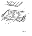
- Fig. 1 shows in an exploded view a generally designated 1 filter unit, which is fastened with its underside on the inner surface of a total of 2 designated oil pan.
- the attachment takes place by means of two magnetic holders 3.
- the number of two magnetic holders 3 is merely exemplary.
- the magnet holder 3 are formed nikringzylindrisch, which corresponds to a preferred embodiment.
- the circular cylindrical magnet holder 3 are received in circular wells 22 in the oil pan 2.
- the magnet holder 3 are used in addition to the attachment of the filter unit 1 and their spacing to the oil pan 2 in the attached state.
- a plurality of elevations 23 formed as domes are furthermore formed in the oil pan 2, on which the filter unit 1 rests directly on the oil pan 2.
- Fig. 2 shows the attached to the oil pan 2 filter unit 1 in a sectional view.
- the filter unit 1 comprises a filter housing 11, which is formed from an upper housing part and a lower housing part, which are joined to one another at a flange 12.
- a filter medium for filtering oil in particular engine and / or transmission oil
- the located in the oil pan 2 and to be filtered oil underflows for this purpose the filter housing 11 and passes through the oil inlet opening 14 in the lower housing part into the interior of the filter unit 1, where it flows through the filter medium and thereby cleaned.
- a nozzle 13 is arranged, at the upper end of which there is an oil outlet opening for the filtered oil.
- the filter housing 11 is fixed by means of the two magnetic holder 3 on the inner surface of the oil pan 2.
- the attachment or holder is based on magnetic holding forces that emanate from the magnetic holders 3, but this is not absolutely necessary, as explained in more detail below (in connection with the Fig. 3 ).
- both the lower housing part of the filter housing 11 and the oil pan 2 are made of a magnetic material, in particular of a ferrous material.
- the upper end surfaces of the magnet holder 3 are in direct contact with the filter housing 11 and the housing lower part and the lower end surfaces are in direct contact with the inner surface of the oil pan 2. At the contact surfaces each magnetic retention is brought about.
- the positional positioning of the filter unit 1 relative to the oil sump 2 likewise takes place via the magnet holders 3.
- the magnet holders 3 are arranged in depressions 22 pointing away from the filter unit 1 in the oil sump 2, which position the magnet holders laterally or radially by positive locking.
- On the housing bottom of the oil pan 2 are facing down, i. in the direction of the oil pan 2 facing elevations or dome 15 is formed, which engage positively and centering in the axial central bore 31 of the circular cylindrical magnet holder 3 (positive attachment to a dome, as already mentioned above).
- Such depressions and / or elevations may be referred to as fixing contours.
- these are integrally formed with the filter housing 11 and / or the oil pan 2.
- a spacing of the lower side of the filter housing 1 from the inner surface of the oil sump 2 takes place via the magnet holders 3.
- a typical spacing value is z. B. 2 to 5 mm. This spacing serves to form a gap which allows the underflow of the filter housing 11 with the oil to be filtered.
- the magnet holders 3 filtering out magnetic solid particles from the oil and binding them to themselves. This is another feature of the magnet holder 3. It is therefore preferred that the magnet holders 3 are arranged in the region of the oil inlet opening 14 of the filter housing 11 in such a way that the oil flowing into the oil inlet opening 14 enters the magnetic influence zone of the magnet holder 3.
- the spacing of the filter housing 11 to the inner surface of the oil pan 2 is further brought about by a plurality of molded in the oil pan 2 dome 23.
- Fig. 3 shows an alternative attachment possibility of the filter unit 1 to the oil pan 2 by means of at least one magnetic holder 3a.
- the attachment or holder is based on positive locking elements in the form of resilient latching hooks 17 and 25 which are arranged on the underside of the filter unit 1 and the lower housing part and the oil pan 2 and the form-fitting the inner peripheral edge and the outer peripheral edge of the circular cylindrical magnet holder 3a embrace as shown.
- the oil pan 2 or the filter housing 11 made of a non-magnetic material, such. As a plastic material or aluminum, be formed.
- spacer elements 41 and 42 are provided, which may be formed as separate elements or integrally formed with the filter housing 11, the oil pan 2 and / or the magnet holder 3a.
- the form-locking elements 17 and 25 can also be formed on the magnet holder 3a or arranged on the latter.
Landscapes
- Engineering & Computer Science (AREA)
- Mechanical Engineering (AREA)
- General Engineering & Computer Science (AREA)
- Lubrication Details And Ventilation Of Internal Combustion Engines (AREA)
- General Details Of Gearings (AREA)
Applications Claiming Priority (2)
| Application Number | Priority Date | Filing Date | Title |
|---|---|---|---|
| DE102009036852.3A DE102009036852B4 (de) | 2009-08-10 | 2009-08-10 | Ölwanne mit einer daran befestigten Ölfiltereinheit |
| EP10006042A EP2284367A3 (fr) | 2009-08-10 | 2010-06-11 | Carter d'huile doté d'un filtre à huile fixée sur celui-ci |
Related Parent Applications (1)
| Application Number | Title | Priority Date | Filing Date |
|---|---|---|---|
| EP10006042A Division EP2284367A3 (fr) | 2009-08-10 | 2010-06-11 | Carter d'huile doté d'un filtre à huile fixée sur celui-ci |
Publications (2)
| Publication Number | Publication Date |
|---|---|
| EP2489841A1 true EP2489841A1 (fr) | 2012-08-22 |
| EP2489841B1 EP2489841B1 (fr) | 2017-03-22 |
Family
ID=43048877
Family Applications (2)
| Application Number | Title | Priority Date | Filing Date |
|---|---|---|---|
| EP10006042A Withdrawn EP2284367A3 (fr) | 2009-08-10 | 2010-06-11 | Carter d'huile doté d'un filtre à huile fixée sur celui-ci |
| EP12001747.0A Not-in-force EP2489841B1 (fr) | 2009-08-10 | 2010-06-11 | Cuve à huile dotée d'une ouverture de filtre à huile fixée sur celle-ci |
Family Applications Before (1)
| Application Number | Title | Priority Date | Filing Date |
|---|---|---|---|
| EP10006042A Withdrawn EP2284367A3 (fr) | 2009-08-10 | 2010-06-11 | Carter d'huile doté d'un filtre à huile fixée sur celui-ci |
Country Status (2)
| Country | Link |
|---|---|
| EP (2) | EP2284367A3 (fr) |
| DE (1) | DE102009036852B4 (fr) |
Families Citing this family (9)
| Publication number | Priority date | Publication date | Assignee | Title |
|---|---|---|---|---|
| JP5624006B2 (ja) * | 2011-10-05 | 2014-11-12 | 本田技研工業株式会社 | オイルフィルター |
| CN103573329B (zh) * | 2013-11-19 | 2017-01-11 | 浙江吉利汽车研究院有限公司 | 一种汽车磁性油底壳 |
| US9291306B2 (en) | 2014-05-08 | 2016-03-22 | Patrick Conlan | Oil filter changing system |
| DE112017006768B4 (de) * | 2017-01-10 | 2023-02-02 | Roman Farkas | Filtereinsatz für ein Haushaltsgerät sowie ein damit versehenes Haushaltsgerät |
| DE102017209987B4 (de) * | 2017-06-13 | 2024-10-10 | Zf Friedrichshafen Ag | Ölwanne eines Getriebes eines Kraftfahrzeugs mit einem Ölfilter und einer Ölwannendichtung |
| DE102017210556A1 (de) | 2017-06-22 | 2018-12-27 | Zf Friedrichshafen Ag | Einheit bestehend aus einer Ölwanne und einem Ölfilter eines Getriebes eines Kraftfahrzeugs |
| DE102021114927A1 (de) | 2021-06-10 | 2022-12-15 | Schaeffler Technologies AG & Co. KG | Ölgehäusewanne mit Ölfilterelement |
| CN113250784B (zh) * | 2021-06-18 | 2022-07-22 | 中国北方发动机研究所(天津) | 一种油底壳结构 |
| DE102024128316A1 (de) * | 2024-09-30 | 2026-04-02 | Voith Patent Gmbh | Ölwanne für eine Antriebseinheit |
Citations (2)
| Publication number | Priority date | Publication date | Assignee | Title |
|---|---|---|---|---|
| DE19735444A1 (de) * | 1997-06-17 | 1999-01-07 | Ibs Filtran Kunststoff Metall | Ölfiltereinsatz für Ölwannen von Motoren und Getrieben |
| US6840042B1 (en) * | 2003-06-17 | 2005-01-11 | Hydro-Gear Limited Partnership | Internal filter |
Family Cites Families (6)
| Publication number | Priority date | Publication date | Assignee | Title |
|---|---|---|---|---|
| JPH0281996U (fr) * | 1988-12-13 | 1990-06-25 | ||
| US4995971A (en) * | 1989-08-07 | 1991-02-26 | Ford Motor Company | Dual purpose automatic transmission oil pan |
| JP4263375B2 (ja) | 2001-02-09 | 2009-05-13 | 矢崎総業株式会社 | 車両表示装置用表示源ユニット |
| US20060180398A1 (en) * | 2005-02-07 | 2006-08-17 | Ibrahim Khalil | Integrated waffle pan apparatus and method |
| DE102005025726A1 (de) * | 2005-06-04 | 2006-12-07 | Ibs Filtran Kunststoff-/ Metallerzeugnisse Gmbh | Befestigungsvorrichtung und Verfahren zur Befestigung eines Bauteils in einer Ölwanne |
| DE102008038958B4 (de) * | 2008-08-13 | 2017-11-02 | Ibs Filtran Kunststoff-/ Metallerzeugnisse Gmbh | Ölwanne mit Ölfilter an Trägereinheit |
-
2009
- 2009-08-10 DE DE102009036852.3A patent/DE102009036852B4/de active Active
-
2010
- 2010-06-11 EP EP10006042A patent/EP2284367A3/fr not_active Withdrawn
- 2010-06-11 EP EP12001747.0A patent/EP2489841B1/fr not_active Not-in-force
Patent Citations (2)
| Publication number | Priority date | Publication date | Assignee | Title |
|---|---|---|---|---|
| DE19735444A1 (de) * | 1997-06-17 | 1999-01-07 | Ibs Filtran Kunststoff Metall | Ölfiltereinsatz für Ölwannen von Motoren und Getrieben |
| US6840042B1 (en) * | 2003-06-17 | 2005-01-11 | Hydro-Gear Limited Partnership | Internal filter |
Also Published As
| Publication number | Publication date |
|---|---|
| EP2284367A2 (fr) | 2011-02-16 |
| DE102009036852A1 (de) | 2011-02-24 |
| DE102009036852B4 (de) | 2015-04-16 |
| EP2489841B1 (fr) | 2017-03-22 |
| EP2284367A3 (fr) | 2011-09-14 |
Similar Documents
| Publication | Publication Date | Title |
|---|---|---|
| EP2489841B1 (fr) | Cuve à huile dotée d'une ouverture de filtre à huile fixée sur celle-ci | |
| EP1339954B1 (fr) | Carter d'huile metallique a filtre a huile integre | |
| EP3096861B1 (fr) | Filtre remplaçable d'un dispositif de filtration et dispositif de filtration | |
| DE60301880T2 (de) | Patronenfilter mit verbesserter abdichtung und verfahren | |
| EP2190556A1 (fr) | Dispositif de filtrage | |
| WO1997041939A1 (fr) | Disque terminal pour element filtrant annulaire a joint agissant radialement | |
| DE102008027662A1 (de) | Ölwanne mit Ölfilter | |
| DE3005448C2 (de) | Filter | |
| EP2154339A1 (fr) | Carter doté d'un filtre à huile sur une unité de support | |
| DE112019003046T5 (de) | Dichtungssysteme und verfahren für ein filtrationssystem | |
| EP1896155B1 (fr) | Dispositif de filtration pour liquides | |
| DE112011100176T5 (de) | Hydrauliksteuergerät | |
| WO2013068120A1 (fr) | Frein à disque, plaque de pression dudit frein à disque et garniture de frein dudit frein à disque | |
| DE602004005628T2 (de) | Halterung mit mehreren Brücken | |
| DE19508815A1 (de) | Luftentölelement | |
| DE202005014125U1 (de) | Abscheider zur Reinigung eines Fluidstromes | |
| DE102015004089A1 (de) | Filtergehäuse und Filterelement für ein Filtersystem | |
| EP2531272B1 (fr) | Pot destiné à recevoir un élément filtrant dans un dispositif de filtration | |
| WO2015011045A1 (fr) | Ensemble maître-cylindre d'un système de freinage de véhicule automobile pourvu d'un élément filtre, et réservoir de fluide et élément d'insertion pour celui-ci | |
| EP2129902B1 (fr) | Filtre pour liquides | |
| DE102012017319A1 (de) | Befestigungsanordnung zwischen einem Radiallager und einem Stützarm sowie Fahrzeug mit einer derartigen Befestigungsanordnung | |
| DE102005034862B3 (de) | Mit einem Polrad versehenes Bauteil und Verfahren zur Herstellung und Montage eines Polrades | |
| DE102012012940A1 (de) | Filterhalterahmen für ein Filtersystem | |
| EP1059465B1 (fr) | Dispositif pour la fixation d'un étrier de frein à un support de roue | |
| DE10146592C1 (de) | Hinterachsträger eines Kraftfahrzeuges |
Legal Events
| Date | Code | Title | Description |
|---|---|---|---|
| PUAI | Public reference made under article 153(3) epc to a published international application that has entered the european phase |
Free format text: ORIGINAL CODE: 0009012 |
|
| AC | Divisional application: reference to earlier application |
Ref document number: 2284367 Country of ref document: EP Kind code of ref document: P |
|
| AK | Designated contracting states |
Kind code of ref document: A1 Designated state(s): AL AT BE BG CH CY CZ DE DK EE ES FI FR GB GR HR HU IE IS IT LI LT LU LV MC MK MT NL NO PL PT RO SE SI SK SM TR |
|
| AX | Request for extension of the european patent |
Extension state: BA ME RS |
|
| 17P | Request for examination filed |
Effective date: 20120926 |
|
| 17Q | First examination report despatched |
Effective date: 20140815 |
|
| GRAP | Despatch of communication of intention to grant a patent |
Free format text: ORIGINAL CODE: EPIDOSNIGR1 |
|
| INTG | Intention to grant announced |
Effective date: 20161011 |
|
| GRAJ | Information related to disapproval of communication of intention to grant by the applicant or resumption of examination proceedings by the epo deleted |
Free format text: ORIGINAL CODE: EPIDOSDIGR1 |
|
| GRAS | Grant fee paid |
Free format text: ORIGINAL CODE: EPIDOSNIGR3 |
|
| GRAP | Despatch of communication of intention to grant a patent |
Free format text: ORIGINAL CODE: EPIDOSNIGR1 |
|
| GRAA | (expected) grant |
Free format text: ORIGINAL CODE: 0009210 |
|
| INTC | Intention to grant announced (deleted) | ||
| INTG | Intention to grant announced |
Effective date: 20170206 |
|
| AC | Divisional application: reference to earlier application |
Ref document number: 2284367 Country of ref document: EP Kind code of ref document: P |
|
| AK | Designated contracting states |
Kind code of ref document: B1 Designated state(s): AL AT BE BG CH CY CZ DE DK EE ES FI FR GB GR HR HU IE IS IT LI LT LU LV MC MK MT NL NO PL PT RO SE SI SK SM TR |
|
| REG | Reference to a national code |
Ref country code: GB Ref legal event code: FG4D Free format text: NOT ENGLISH |
|
| REG | Reference to a national code |
Ref country code: CH Ref legal event code: EP |
|
| REG | Reference to a national code |
Ref country code: AT Ref legal event code: REF Ref document number: 878016 Country of ref document: AT Kind code of ref document: T Effective date: 20170415 |
|
| REG | Reference to a national code |
Ref country code: IE Ref legal event code: FG4D Free format text: LANGUAGE OF EP DOCUMENT: GERMAN |
|
| REG | Reference to a national code |
Ref country code: DE Ref legal event code: R096 Ref document number: 502010013362 Country of ref document: DE |
|
| REG | Reference to a national code |
Ref country code: NL Ref legal event code: FP Ref country code: FR Ref legal event code: PLFP Year of fee payment: 8 |
|
| PG25 | Lapsed in a contracting state [announced via postgrant information from national office to epo] |
Ref country code: GR Free format text: LAPSE BECAUSE OF FAILURE TO SUBMIT A TRANSLATION OF THE DESCRIPTION OR TO PAY THE FEE WITHIN THE PRESCRIBED TIME-LIMIT Effective date: 20170623 Ref country code: NO Free format text: LAPSE BECAUSE OF FAILURE TO SUBMIT A TRANSLATION OF THE DESCRIPTION OR TO PAY THE FEE WITHIN THE PRESCRIBED TIME-LIMIT Effective date: 20170622 Ref country code: FI Free format text: LAPSE BECAUSE OF FAILURE TO SUBMIT A TRANSLATION OF THE DESCRIPTION OR TO PAY THE FEE WITHIN THE PRESCRIBED TIME-LIMIT Effective date: 20170322 Ref country code: HR Free format text: LAPSE BECAUSE OF FAILURE TO SUBMIT A TRANSLATION OF THE DESCRIPTION OR TO PAY THE FEE WITHIN THE PRESCRIBED TIME-LIMIT Effective date: 20170322 Ref country code: LT Free format text: LAPSE BECAUSE OF FAILURE TO SUBMIT A TRANSLATION OF THE DESCRIPTION OR TO PAY THE FEE WITHIN THE PRESCRIBED TIME-LIMIT Effective date: 20170322 |
|
| REG | Reference to a national code |
Ref country code: LT Ref legal event code: MG4D |
|
| PG25 | Lapsed in a contracting state [announced via postgrant information from national office to epo] |
Ref country code: LV Free format text: LAPSE BECAUSE OF FAILURE TO SUBMIT A TRANSLATION OF THE DESCRIPTION OR TO PAY THE FEE WITHIN THE PRESCRIBED TIME-LIMIT Effective date: 20170322 Ref country code: SE Free format text: LAPSE BECAUSE OF FAILURE TO SUBMIT A TRANSLATION OF THE DESCRIPTION OR TO PAY THE FEE WITHIN THE PRESCRIBED TIME-LIMIT Effective date: 20170322 Ref country code: BG Free format text: LAPSE BECAUSE OF FAILURE TO SUBMIT A TRANSLATION OF THE DESCRIPTION OR TO PAY THE FEE WITHIN THE PRESCRIBED TIME-LIMIT Effective date: 20170622 |
|
| PG25 | Lapsed in a contracting state [announced via postgrant information from national office to epo] |
Ref country code: SK Free format text: LAPSE BECAUSE OF FAILURE TO SUBMIT A TRANSLATION OF THE DESCRIPTION OR TO PAY THE FEE WITHIN THE PRESCRIBED TIME-LIMIT Effective date: 20170322 Ref country code: EE Free format text: LAPSE BECAUSE OF FAILURE TO SUBMIT A TRANSLATION OF THE DESCRIPTION OR TO PAY THE FEE WITHIN THE PRESCRIBED TIME-LIMIT Effective date: 20170322 Ref country code: ES Free format text: LAPSE BECAUSE OF FAILURE TO SUBMIT A TRANSLATION OF THE DESCRIPTION OR TO PAY THE FEE WITHIN THE PRESCRIBED TIME-LIMIT Effective date: 20170322 Ref country code: RO Free format text: LAPSE BECAUSE OF FAILURE TO SUBMIT A TRANSLATION OF THE DESCRIPTION OR TO PAY THE FEE WITHIN THE PRESCRIBED TIME-LIMIT Effective date: 20170322 Ref country code: CZ Free format text: LAPSE BECAUSE OF FAILURE TO SUBMIT A TRANSLATION OF THE DESCRIPTION OR TO PAY THE FEE WITHIN THE PRESCRIBED TIME-LIMIT Effective date: 20170322 |
|
| PG25 | Lapsed in a contracting state [announced via postgrant information from national office to epo] |
Ref country code: PL Free format text: LAPSE BECAUSE OF FAILURE TO SUBMIT A TRANSLATION OF THE DESCRIPTION OR TO PAY THE FEE WITHIN THE PRESCRIBED TIME-LIMIT Effective date: 20170322 Ref country code: SM Free format text: LAPSE BECAUSE OF FAILURE TO SUBMIT A TRANSLATION OF THE DESCRIPTION OR TO PAY THE FEE WITHIN THE PRESCRIBED TIME-LIMIT Effective date: 20170322 Ref country code: PT Free format text: LAPSE BECAUSE OF FAILURE TO SUBMIT A TRANSLATION OF THE DESCRIPTION OR TO PAY THE FEE WITHIN THE PRESCRIBED TIME-LIMIT Effective date: 20170724 Ref country code: IS Free format text: LAPSE BECAUSE OF FAILURE TO SUBMIT A TRANSLATION OF THE DESCRIPTION OR TO PAY THE FEE WITHIN THE PRESCRIBED TIME-LIMIT Effective date: 20170722 |
|
| REG | Reference to a national code |
Ref country code: DE Ref legal event code: R097 Ref document number: 502010013362 Country of ref document: DE |
|
| REG | Reference to a national code |
Ref country code: DE Ref legal event code: R119 Ref document number: 502010013362 Country of ref document: DE |
|
| PLBE | No opposition filed within time limit |
Free format text: ORIGINAL CODE: 0009261 |
|
| STAA | Information on the status of an ep patent application or granted ep patent |
Free format text: STATUS: NO OPPOSITION FILED WITHIN TIME LIMIT |
|
| PG25 | Lapsed in a contracting state [announced via postgrant information from national office to epo] |
Ref country code: DK Free format text: LAPSE BECAUSE OF FAILURE TO SUBMIT A TRANSLATION OF THE DESCRIPTION OR TO PAY THE FEE WITHIN THE PRESCRIBED TIME-LIMIT Effective date: 20170322 Ref country code: MC Free format text: LAPSE BECAUSE OF FAILURE TO SUBMIT A TRANSLATION OF THE DESCRIPTION OR TO PAY THE FEE WITHIN THE PRESCRIBED TIME-LIMIT Effective date: 20170322 |
|
| REG | Reference to a national code |
Ref country code: CH Ref legal event code: PL |
|
| 26N | No opposition filed |
Effective date: 20180102 |
|
| GBPC | Gb: european patent ceased through non-payment of renewal fee |
Effective date: 20170622 |
|
| PG25 | Lapsed in a contracting state [announced via postgrant information from national office to epo] |
Ref country code: SI Free format text: LAPSE BECAUSE OF FAILURE TO SUBMIT A TRANSLATION OF THE DESCRIPTION OR TO PAY THE FEE WITHIN THE PRESCRIBED TIME-LIMIT Effective date: 20170322 |
|
| REG | Reference to a national code |
Ref country code: IE Ref legal event code: MM4A |
|
| PG25 | Lapsed in a contracting state [announced via postgrant information from national office to epo] |
Ref country code: DE Free format text: LAPSE BECAUSE OF NON-PAYMENT OF DUE FEES Effective date: 20180103 Ref country code: CH Free format text: LAPSE BECAUSE OF NON-PAYMENT OF DUE FEES Effective date: 20170630 Ref country code: GB Free format text: LAPSE BECAUSE OF NON-PAYMENT OF DUE FEES Effective date: 20170622 Ref country code: LU Free format text: LAPSE BECAUSE OF NON-PAYMENT OF DUE FEES Effective date: 20170611 Ref country code: LI Free format text: LAPSE BECAUSE OF NON-PAYMENT OF DUE FEES Effective date: 20170630 Ref country code: IE Free format text: LAPSE BECAUSE OF NON-PAYMENT OF DUE FEES Effective date: 20170611 |
|
| REG | Reference to a national code |
Ref country code: BE Ref legal event code: MM Effective date: 20170630 |
|
| REG | Reference to a national code |
Ref country code: FR Ref legal event code: PLFP Year of fee payment: 9 |
|
| PGFP | Annual fee paid to national office [announced via postgrant information from national office to epo] |
Ref country code: NL Payment date: 20180620 Year of fee payment: 9 |
|
| REG | Reference to a national code |
Ref country code: AT Ref legal event code: MM01 Ref document number: 878016 Country of ref document: AT Kind code of ref document: T Effective date: 20170611 |
|
| PG25 | Lapsed in a contracting state [announced via postgrant information from national office to epo] |
Ref country code: BE Free format text: LAPSE BECAUSE OF NON-PAYMENT OF DUE FEES Effective date: 20170630 |
|
| PGFP | Annual fee paid to national office [announced via postgrant information from national office to epo] |
Ref country code: FR Payment date: 20180620 Year of fee payment: 9 |
|
| PG25 | Lapsed in a contracting state [announced via postgrant information from national office to epo] |
Ref country code: MT Free format text: LAPSE BECAUSE OF FAILURE TO SUBMIT A TRANSLATION OF THE DESCRIPTION OR TO PAY THE FEE WITHIN THE PRESCRIBED TIME-LIMIT Effective date: 20170322 |
|
| PGFP | Annual fee paid to national office [announced via postgrant information from national office to epo] |
Ref country code: IT Payment date: 20180627 Year of fee payment: 9 |
|
| PG25 | Lapsed in a contracting state [announced via postgrant information from national office to epo] |
Ref country code: AT Free format text: LAPSE BECAUSE OF NON-PAYMENT OF DUE FEES Effective date: 20170611 |
|
| PG25 | Lapsed in a contracting state [announced via postgrant information from national office to epo] |
Ref country code: HU Free format text: LAPSE BECAUSE OF FAILURE TO SUBMIT A TRANSLATION OF THE DESCRIPTION OR TO PAY THE FEE WITHIN THE PRESCRIBED TIME-LIMIT; INVALID AB INITIO Effective date: 20100611 |
|
| PG25 | Lapsed in a contracting state [announced via postgrant information from national office to epo] |
Ref country code: CY Free format text: LAPSE BECAUSE OF NON-PAYMENT OF DUE FEES Effective date: 20170322 |
|
| PG25 | Lapsed in a contracting state [announced via postgrant information from national office to epo] |
Ref country code: MK Free format text: LAPSE BECAUSE OF FAILURE TO SUBMIT A TRANSLATION OF THE DESCRIPTION OR TO PAY THE FEE WITHIN THE PRESCRIBED TIME-LIMIT Effective date: 20170322 |
|
| REG | Reference to a national code |
Ref country code: NL Ref legal event code: MM Effective date: 20190701 |
|
| PG25 | Lapsed in a contracting state [announced via postgrant information from national office to epo] |
Ref country code: TR Free format text: LAPSE BECAUSE OF FAILURE TO SUBMIT A TRANSLATION OF THE DESCRIPTION OR TO PAY THE FEE WITHIN THE PRESCRIBED TIME-LIMIT Effective date: 20170322 |
|
| PG25 | Lapsed in a contracting state [announced via postgrant information from national office to epo] |
Ref country code: NL Free format text: LAPSE BECAUSE OF NON-PAYMENT OF DUE FEES Effective date: 20190701 Ref country code: IT Free format text: LAPSE BECAUSE OF NON-PAYMENT OF DUE FEES Effective date: 20190611 |
|
| PG25 | Lapsed in a contracting state [announced via postgrant information from national office to epo] |
Ref country code: FR Free format text: LAPSE BECAUSE OF NON-PAYMENT OF DUE FEES Effective date: 20190630 |
|
| PG25 | Lapsed in a contracting state [announced via postgrant information from national office to epo] |
Ref country code: AL Free format text: LAPSE BECAUSE OF FAILURE TO SUBMIT A TRANSLATION OF THE DESCRIPTION OR TO PAY THE FEE WITHIN THE PRESCRIBED TIME-LIMIT Effective date: 20170322 |