EP2490320A2 - Kühlung einer elektrischen Permanentmagnetmaschine - Google Patents
Kühlung einer elektrischen Permanentmagnetmaschine Download PDFInfo
- Publication number
- EP2490320A2 EP2490320A2 EP12156096A EP12156096A EP2490320A2 EP 2490320 A2 EP2490320 A2 EP 2490320A2 EP 12156096 A EP12156096 A EP 12156096A EP 12156096 A EP12156096 A EP 12156096A EP 2490320 A2 EP2490320 A2 EP 2490320A2
- Authority
- EP
- European Patent Office
- Prior art keywords
- electric machine
- stator
- rotor
- thermal energy
- fluid coolant
- Prior art date
- Legal status (The legal status is an assumption and is not a legal conclusion. Google has not performed a legal analysis and makes no representation as to the accuracy of the status listed.)
- Granted
Links
Images


Classifications
-
- H—ELECTRICITY
- H02—GENERATION; CONVERSION OR DISTRIBUTION OF ELECTRIC POWER
- H02K—DYNAMO-ELECTRIC MACHINES
- H02K9/00—Arrangements for cooling or ventilating
- H02K9/19—Arrangements for cooling or ventilating for machines with closed casing and closed-circuit cooling using a liquid cooling medium, e.g. oil
- H02K9/197—Arrangements for cooling or ventilating for machines with closed casing and closed-circuit cooling using a liquid cooling medium, e.g. oil in which the rotor or stator space is fluid-tight, e.g. to provide for different cooling media for rotor and stator
-
- H—ELECTRICITY
- H02—GENERATION; CONVERSION OR DISTRIBUTION OF ELECTRIC POWER
- H02K—DYNAMO-ELECTRIC MACHINES
- H02K1/00—Details of the magnetic circuit
- H02K1/06—Details of the magnetic circuit characterised by the shape, form or construction
- H02K1/22—Rotating parts of the magnetic circuit
- H02K1/27—Rotor cores with permanent magnets
- H02K1/2786—Outer rotors
- H02K1/2787—Outer rotors the magnetisation axis of the magnets being perpendicular to the rotor axis
- H02K1/2789—Outer rotors the magnetisation axis of the magnets being perpendicular to the rotor axis the rotor consisting of two or more circumferentially positioned magnets
- H02K1/2791—Surface mounted magnets; Inset magnets
-
- H—ELECTRICITY
- H02—GENERATION; CONVERSION OR DISTRIBUTION OF ELECTRIC POWER
- H02K—DYNAMO-ELECTRIC MACHINES
- H02K5/00—Casings; Enclosures; Supports
- H02K5/04—Casings or enclosures characterised by the shape, form or construction thereof
- H02K5/20—Casings or enclosures characterised by the shape, form or construction thereof with channels or ducts for flow of cooling medium
- H02K5/203—Casings or enclosures characterised by the shape, form or construction thereof with channels or ducts for flow of cooling medium specially adapted for liquids, e.g. cooling jackets
-
- H—ELECTRICITY
- H02—GENERATION; CONVERSION OR DISTRIBUTION OF ELECTRIC POWER
- H02K—DYNAMO-ELECTRIC MACHINES
- H02K9/00—Arrangements for cooling or ventilating
- H02K9/08—Arrangements for cooling or ventilating by gaseous cooling medium circulating wholly within the machine casing
Definitions
- the subject matter disclosed herein relates to electric machines. More specifically, the subject disclosure relates to cooling of permanent magnet electric machines.
- Permanent magnet electric machines such as motors and generators have been in use for many years. Permanent magnet machines have been favored over other types due to their efficiency, simplicity, robustness and tolerance to large radial air gaps between the rotor and the stator of the machine. Permanent magnet machines, however, require cooling of the permanent magnets to prevent demagnetization of the permanent magnets. This begins to occur generally for some magnet materials when the permanent magnets exceed a temperature of about 200 degrees Celsius, while others can begin to demagnetize at lower temperatures. Once demagnetization occurs, the electric machine is no longer capable of meeting specified performance targets.
- the machine may be designed with enough excess capability to reduce the magnet thermal load. This, however, results in machines that are overly physically large.
- Other machines utilize a fan to introduce relatively cool air to the permanent magnet surfaces. This type of cooling cannot be used, however, when the machine needs to be sealed from the outside environment.
- a third method is to flood the rotor cavity of the machine with coolant. This is useful in machines that must be sealed from the outside environment, but windage losses on the rotor, due to the presence of the coolant can impact efficiency of the machine rather severely.
- a fourth method utilizes an active system where coolant is sprayed directly onto the magnets or is circulated through the rotor assembly. This approach typically requires a lubrication system and scavenge system, especially if the machine cannot gravity drain.
- a cooling system for a sealed permanent magnet electric machine includes one or more flow driving devices disposed at a rotor of the electric machine configured to urge an airflow across a plurality of permanent magnets of the rotor and across a plurality of stator end turns of the electric machine to remove thermal energy therefrom.
- a plurality of cooling channels are located in the electric machine in thermal communication with the stator configured to transfer thermal energy from the stator to a flow of fluid coolant through the plurality of cooling channels.
- a heat exchanger is in thermal communication with the plurality of cooling channels to transfer thermal energy from the airflow to the fluid coolant.
- a permanent magnet electric machine includes a rotor including a plurality of permanent magnets and a stator in magnetic communication with the rotor and positioned defining a radial air gap between the rotor and the stator.
- a housing is configured to seal the rotor and the stator from an outside environment.
- a plurality of fan blades are secured to the rotor and configured to urge an airflow across the plurality of permanent magnets and across a plurality of stator end turns of the stator to remove thermal energy therefrom.
- a plurality of cooling channels are located in the electric machine in thermal communication with the stator and are configured to transfer thermal energy from the stator to a flow of fluid coolant through the plurality of cooling channels.
- a heat exchanger is located in thermal communication with the plurality of cooling channels to transfer thermal energy from the airflow to the fluid coolant.
- a method of cooling a sealed permanent magnet electric machine includes moving a flow of fluid coolant through a plurality of cooling channels in thermal communication with a stator of the electric machine and transferring thermal energy from the stator to the fluid coolant flowing through the plurality of cooling channels.
- a circulation of air inside of the housing is urged via rotation of a plurality of fan blades about a machine axis of the electric machine.
- the circulation of air is directed past a plurality of permanent magnets of a rotor of the electric machine and past a plurality of stator end turns of the stator. Thermal energy is transferred from the plurality of permanent magnets and from the plurality of stator end turns to the air and the thermal energy is transferred from the air to the fluid coolant.
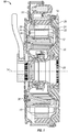
- Figure 1 is a cross-sectional view of an embodiment of an electric machine
- Figure 2 is another cross-sectional view of an embodiment of an electric machine.
- Figure 3 is a partial cross-sectional view of an embodiment of a rotor of an electric machine.
- FIG. 1 Shown in FIG. 1 is a cross-sectional view of a permanent magnet electric machine 10.
- the electric machine 10 includes a rotor 12 rotatably located at an electric machine axis 14.
- the rotor 12 includes a plurality of permanent magnets 16.
- the electric machine of FIG. 1 is an inside out electric machine, meaning that the plurality of permanent magnets 16 are located radially outboard of a stator 18.
- the stator 18 includes at least one stator winding 20 located at a stator core 22 and having a plurality of end turns 24 where the winding 20 emerges from the stator core 22, and changes direction to reenter the stator core 22.
- the stator winding 20 is magnetically interactive with the permanent magnets 16.
- the rotor 12 and stator 18 are located inside of a housing 26 which seals the electric machine 10 from the outside environment.
- the rotor 12 To locate the permanent magnets 16 radially outboard of the stator 18, the rotor 12 includes a rotor hub 28 located at the axis 14.
- a rotor disc 30, which may also take the form of, for example, a plurality of rotor arms, extends radially outwardly from the rotor hub 28.
- the plurality of permanent magnets 16 are supported by the rotor disc 30 radially outboard of the stator 18.
- FIG. 2 illustrates a flow of cooling matter through the electric machine 10.
- Two cooling loops circulate cooling matter through the electric machine 10.
- a liquid cooling block 32 is located radially inboard of the stator 18 and substantially abuts the stator core 22 or other stator 18 component, such as the stator winding 20.
- the liquid cooling block 32 includes a plurality of cooling channels 34 arranged therein.
- the plurality of cooling channels 34 extend circumferentially around the electric machine 10. It is to be appreciated, however, that other arrangements of cooling channels 34, for example labyrinthine or axially-extending cooling channels 34 or cooling pins / fins are contemplated within the scope of the present disclosure. While the coolant channels 34 of the pictured embodiment are located in the cooling block 32, it is to be appreciated that in some embodiments the coolant block 32 is not utilized and the cooling channels may be located, for example, directly in the stator core 22.
- One or more coolant inlets 36 and one or more coolant outlets 38 are located in the cooling block 32 and are connected to the plurality of cooling channels 34 for input of coolant to and output of coolant from the plurality of cooling channels 34.
- the coolant inlets 36 and coolant outlets extend through the housing 26.
- the coolant is, for example, water, or a mixture of water and ethylene glycol, or a mixture of water and propylene glycol, oil, forced air, liquid salt, or any other suitable fluid or gas. Coolant is input into the plurality of cooling channels 34 via the one or more coolant inlets 36 from a coolant source (not shown). As the coolant flows through the plurality of cooling channels 34, as shown in FIG.
- thermal energy is transferred to the coolant from the stator 18.
- the coolant flows through the plurality of cooling channels 34 without entering the rotor 12.
- the coolant exits the housing 26 via the one or more coolant outlets 38 and the thermal energy is dissipated external to the electric machine 10.
- the electric machine 10 further includes an air cooling circuit. Even though the electric machine 10 is sealed from the outside environment, a volume of air is present inside the housing 26. Rotation of the rotor 12 urges a flow of air radially outwardly toward the stator end turns 24 and the plurality of permanent magnets 16. To facilitate this flow or air, one or more flow-driving devices are disposed at the rotor 12. For example, as shown in FIG. 2 , the rotor 12 includes a plurality of fan blades 40 secured to, or integral to, the rotor disc 30.
- the plurality of fan blades 40 are located radially inboard of the stator end turns 24 and are secured top the rotor disc 26 such that rotation of the rotor 12 about the machine axis 14 drives rotation of the fan blades 40 about the machine axis 14.
- the fan blades 40 add head to the volume of air in the housing 26 forcing the air toward the permanent magnets 16 and/or the stator end turns 24.
- the plurality of fan blades 40 may have more than one configuration.
- tall fan blades 40a are configured to direct air directly toward the stator end turns 24, while short fan blades 40b interposed between tall fan blades 40a allow at least a portion of the flow of air to bypass the stator end turns and flow directly to the permanent magnets 16.
- a portion of the flow of air flows past and through the stator end turns 24, removing thermal energy therefrom. Another portion of the flow of air flows across the plurality of permanent magnets 16, removing thermal energy from the permanent magnets 16.
- the airflow then is urged through a water to air heat exchanger 42.
- the heat exchanger 42 includes a plurality of heat exchanger channels 44 through which the airflow is urged. Thermal energy is transferred from the airflow into the heat exchanger 42, then from the heat exchanger 42 to the liquid coolant flowing through the cooling channels 34. The thermal energy is then dissipated outside the electric machine 10 via the liquid coolant exiting the electric machine through the one or more coolant exits 38.
- the heat exchanger 42 may be formed integral to the housing 26, and may be formed by casting to reduce the cost of the heat exchanger 42.
- the rotor 12 utilizing the fan blades 40, maintains the flow of air through the machine such that when the heat is removed in the heat exchanger 42, the air circulates back to the stator end turns 24 and the permanent magnets 16 to absorb more thermal energy therefrom.
Landscapes
- Engineering & Computer Science (AREA)
- Power Engineering (AREA)
- Motor Or Generator Cooling System (AREA)
Applications Claiming Priority (1)
| Application Number | Priority Date | Filing Date | Title |
|---|---|---|---|
| US13/030,751 US8760015B2 (en) | 2011-02-18 | 2011-02-18 | Cooling of permanent magnet electric machine |
Publications (3)
| Publication Number | Publication Date |
|---|---|
| EP2490320A2 true EP2490320A2 (de) | 2012-08-22 |
| EP2490320A3 EP2490320A3 (de) | 2016-06-15 |
| EP2490320B1 EP2490320B1 (de) | 2021-06-30 |
Family
ID=45607116
Family Applications (1)
| Application Number | Title | Priority Date | Filing Date |
|---|---|---|---|
| EP12156096.5A Active EP2490320B1 (de) | 2011-02-18 | 2012-02-17 | Kühlung einer elektrischen Permanentmagnetmaschine |
Country Status (2)
| Country | Link |
|---|---|
| US (1) | US8760015B2 (de) |
| EP (1) | EP2490320B1 (de) |
Families Citing this family (8)
| Publication number | Priority date | Publication date | Assignee | Title |
|---|---|---|---|---|
| US8760016B2 (en) * | 2011-07-29 | 2014-06-24 | Exelis Inc. | Electric machine with enhanced cooling |
| US9006943B2 (en) | 2012-09-12 | 2015-04-14 | Remy Technologies, L.L.C. | Electro-dynamic machine with coolant chargeable bladder |
| US9306428B2 (en) * | 2012-09-19 | 2016-04-05 | Remy Technologies, Llc | Motor cooling system with potted end turns |
| WO2016057582A1 (en) * | 2014-10-08 | 2016-04-14 | Remy Technologies, Llc | Axially extending electric machine electronics cooling tower |
| US20160118863A1 (en) * | 2014-10-27 | 2016-04-28 | Hamilton Sundstrand Corporation | Two-phase electric motor cooler |
| JP6111283B2 (ja) * | 2015-04-24 | 2017-04-05 | 本田技研工業株式会社 | ステータの冷却構造 |
| US11336151B2 (en) | 2019-05-06 | 2022-05-17 | Rolls-Royce Plc | Fluid cooling of grease-packed bearings |
| JP2023516064A (ja) * | 2020-03-02 | 2023-04-17 | ファルコン・パワー,エルエルシー | 調節可能ハルバッハ磁石配列を用いる可変トルク発電電気機械 |
Family Cites Families (27)
| Publication number | Priority date | Publication date | Assignee | Title |
|---|---|---|---|---|
| US4514652A (en) | 1983-07-13 | 1985-04-30 | Sundstrand Corporation | Liquid cooled high speed synchronous machine |
| US4745315A (en) * | 1983-12-15 | 1988-05-17 | General Electric Company | Brushless exciter with zero-gravity rectifier assembly |
| US4647805A (en) | 1985-12-16 | 1987-03-03 | Sundstrand Corporation | Dynamoelectric machine |
| US4862024A (en) | 1987-12-14 | 1989-08-29 | United Technologies Corp. | Heat dissipation in an electric motor |
| US4839547A (en) * | 1988-03-28 | 1989-06-13 | Wertec Corporation | Motor frame and motor with increased cooling capacity |
| US4994700A (en) | 1990-02-15 | 1991-02-19 | Sundstrand Corporation | Dynamoelectric machine oil-cooled stator winding |
| US5363003A (en) * | 1991-06-06 | 1994-11-08 | Nippon Densan Corporation | Motor and circuitry for protecting same |
| TW263629B (de) * | 1992-05-27 | 1995-11-21 | Nihon Densan Kk | |
| JPH07194079A (ja) * | 1993-12-27 | 1995-07-28 | Matsushita Electric Ind Co Ltd | 永久磁石直流モータ |
| JP3363682B2 (ja) * | 1995-12-19 | 2003-01-08 | 株式会社ミツバ | 磁石発電機 |
| DE19629346C2 (de) * | 1996-07-20 | 1998-05-14 | Mannesmann Sachs Ag | Hybridantrieb |
| JP3017953B2 (ja) * | 1996-07-24 | 2000-03-13 | 株式会社東芝 | 電動機の回転子及びその製造方法 |
| JP3688898B2 (ja) * | 1998-08-21 | 2005-08-31 | 株式会社東芝 | 電動機のロータ |
| US6239520B1 (en) | 2000-04-24 | 2001-05-29 | Capstone Turbine Corporation | Permanent magnet rotor cooling system and method |
| US6727609B2 (en) | 2001-08-08 | 2004-04-27 | Hamilton Sundstrand Corporation | Cooling of a rotor for a rotary electric machine |
| US7262526B2 (en) * | 2002-06-20 | 2007-08-28 | Kabushiki Kaisha Toshiba | Rotor for permanent magnet motor of outer rotor type |
| US7327055B2 (en) | 2002-07-26 | 2008-02-05 | John Devine | Permanent magnet generator with an integral cooling system |
| JP4162565B2 (ja) * | 2003-09-30 | 2008-10-08 | 株式会社東芝 | 電動機のロータ |
| US7009317B2 (en) * | 2004-01-14 | 2006-03-07 | Caterpillar Inc. | Cooling system for an electric motor |
| DE102005049261B3 (de) * | 2005-10-14 | 2007-03-29 | Siemens Ag | Kühlerlüfter für ein Kraftfahrzeug |
| DE102006005316B4 (de) | 2006-02-06 | 2020-03-26 | Siemens Aktiengesellschaft | Kühleinrichtung für eine elektrische Maschine, elektrische Maschinen mit einer solchen Kühleinrichtung, Dynamoblech sowie Herstellungsverfahren für solche elektrischen Maschinen |
| JP4800847B2 (ja) * | 2006-06-01 | 2011-10-26 | 三菱電機株式会社 | 全閉形液冷電動機 |
| US7701095B2 (en) | 2006-07-28 | 2010-04-20 | Danotek Motion Technologies | Permanent-magnet generator and method of cooling |
| JP4757238B2 (ja) * | 2007-07-13 | 2011-08-24 | アイシン・エィ・ダブリュ株式会社 | 回転電機の冷却構造及び冷却方法 |
| DE102007061597B4 (de) * | 2007-12-20 | 2010-01-14 | Siemens Ag | Elektrische Maschine mit Doppelaxiallüfter |
| US8089189B2 (en) * | 2009-06-23 | 2012-01-03 | Hamilton Sundstrand Corporation | Rotor for permanent magnet electric machine |
| CN101764468B (zh) * | 2010-03-04 | 2012-05-09 | 东元总合科技(杭州)有限公司 | 密闭式永磁同步电动机 |
-
2011
- 2011-02-18 US US13/030,751 patent/US8760015B2/en active Active
-
2012
- 2012-02-17 EP EP12156096.5A patent/EP2490320B1/de active Active
Non-Patent Citations (1)
| Title |
|---|
| None |
Also Published As
| Publication number | Publication date |
|---|---|
| EP2490320B1 (de) | 2021-06-30 |
| US8760015B2 (en) | 2014-06-24 |
| US20120212083A1 (en) | 2012-08-23 |
| EP2490320A3 (de) | 2016-06-15 |
Similar Documents
| Publication | Publication Date | Title |
|---|---|---|
| EP2490320B1 (de) | Kühlung einer elektrischen Permanentmagnetmaschine | |
| EP2573906B1 (de) | Elektrische Maschine mit verminderten Ventilationsverlusten | |
| US9960649B2 (en) | Rotating electric machine | |
| EP2667486B1 (de) | Verfahren zur Kühlung eines Rotors eines elektrischen Motors | |
| JP5625565B2 (ja) | 回転機及び車両 | |
| EP2490323B1 (de) | Kühlung einer elektrischen Permanentmagnetmaschine | |
| US20140265657A1 (en) | Electric machine with liquid cooling and method of assembling | |
| JP2013162674A (ja) | 回転電機 | |
| CA2817064C (en) | Axial flux electrical machines | |
| US11073136B2 (en) | Cooling arrangement | |
| WO2012080566A1 (en) | An electrical machine | |
| US8847444B2 (en) | Cooling of permanent magnet electric machine | |
| EP3716448A1 (de) | Endwindungskühlung | |
| EP2752977A2 (de) | Kühlsystem für eine elektrische Maschine und Verfahren zum Zusammenbau derselben | |
| US20220190682A1 (en) | Motor-cooling apparatus | |
| JP2017060319A (ja) | 電動機の冷却構造。 | |
| CA2737989A1 (en) | Electric machine | |
| US20180006531A1 (en) | Internal closed loop cooling | |
| EP2602916A1 (de) | Kühlung einer elektrischen Permanentmagnetmaschine | |
| CN103187829A (zh) | 永磁电机的冷却 | |
| JP2012210120A (ja) | 回転電機 | |
| EP3024126A1 (de) | Kühlanordnung | |
| KR20150068224A (ko) | 구동모터의 냉각유닛 | |
| US11038390B2 (en) | Electrical machine apparatus having a conduit with a particular arrangement for an inlet and outlet | |
| CN111030371B (zh) | 一种单相电机 |
Legal Events
| Date | Code | Title | Description |
|---|---|---|---|
| PUAI | Public reference made under article 153(3) epc to a published international application that has entered the european phase |
Free format text: ORIGINAL CODE: 0009012 |
|
| AK | Designated contracting states |
Kind code of ref document: A2 Designated state(s): AL AT BE BG CH CY CZ DE DK EE ES FI FR GB GR HR HU IE IS IT LI LT LU LV MC MK MT NL NO PL PT RO RS SE SI SK SM TR |
|
| AX | Request for extension of the european patent |
Extension state: BA ME |
|
| REG | Reference to a national code |
Ref country code: DE Ref legal event code: R079 Ref document number: 602012075948 Country of ref document: DE Free format text: PREVIOUS MAIN CLASS: H02K0001270000 Ipc: H02K0009197000 |
|
| PUAL | Search report despatched |
Free format text: ORIGINAL CODE: 0009013 |
|
| AK | Designated contracting states |
Kind code of ref document: A3 Designated state(s): AL AT BE BG CH CY CZ DE DK EE ES FI FR GB GR HR HU IE IS IT LI LT LU LV MC MK MT NL NO PL PT RO RS SE SI SK SM TR |
|
| AX | Request for extension of the european patent |
Extension state: BA ME |
|
| RIC1 | Information provided on ipc code assigned before grant |
Ipc: H02K 1/27 20060101ALN20160509BHEP Ipc: H02K 9/197 20060101AFI20160509BHEP Ipc: H02K 5/20 20060101ALN20160509BHEP Ipc: H02K 9/08 20060101ALI20160509BHEP |
|
| STAA | Information on the status of an ep patent application or granted ep patent |
Free format text: STATUS: REQUEST FOR EXAMINATION WAS MADE |
|
| 17P | Request for examination filed |
Effective date: 20161213 |
|
| RBV | Designated contracting states (corrected) |
Designated state(s): AL AT BE BG CH CY CZ DE DK EE ES FI FR GB GR HR HU IE IS IT LI LT LU LV MC MK MT NL NO PL PT RO RS SE SI SK SM TR |
|
| STAA | Information on the status of an ep patent application or granted ep patent |
Free format text: STATUS: EXAMINATION IS IN PROGRESS |
|
| 17Q | First examination report despatched |
Effective date: 20181113 |
|
| GRAP | Despatch of communication of intention to grant a patent |
Free format text: ORIGINAL CODE: EPIDOSNIGR1 |
|
| STAA | Information on the status of an ep patent application or granted ep patent |
Free format text: STATUS: GRANT OF PATENT IS INTENDED |
|
| INTG | Intention to grant announced |
Effective date: 20201217 |
|
| RAP3 | Party data changed (applicant data changed or rights of an application transferred) |
Owner name: HAMILTON SUNDSTRAND SPACE SYSTEMS INTERNATIONAL, INC. |
|
| GRAS | Grant fee paid |
Free format text: ORIGINAL CODE: EPIDOSNIGR3 |
|
| GRAA | (expected) grant |
Free format text: ORIGINAL CODE: 0009210 |
|
| STAA | Information on the status of an ep patent application or granted ep patent |
Free format text: STATUS: THE PATENT HAS BEEN GRANTED |
|
| AK | Designated contracting states |
Kind code of ref document: B1 Designated state(s): AL AT BE BG CH CY CZ DE DK EE ES FI FR GB GR HR HU IE IS IT LI LT LU LV MC MK MT NL NO PL PT RO RS SE SI SK SM TR |
|
| REG | Reference to a national code |
Ref country code: GB Ref legal event code: FG4D Ref country code: CH Ref legal event code: EP |
|
| REG | Reference to a national code |
Ref country code: DE Ref legal event code: R096 Ref document number: 602012075948 Country of ref document: DE Ref country code: AT Ref legal event code: REF Ref document number: 1407273 Country of ref document: AT Kind code of ref document: T Effective date: 20210715 |
|
| REG | Reference to a national code |
Ref country code: IE Ref legal event code: FG4D |
|
| REG | Reference to a national code |
Ref country code: LT Ref legal event code: MG9D |
|
| PG25 | Lapsed in a contracting state [announced via postgrant information from national office to epo] |
Ref country code: FI Free format text: LAPSE BECAUSE OF FAILURE TO SUBMIT A TRANSLATION OF THE DESCRIPTION OR TO PAY THE FEE WITHIN THE PRESCRIBED TIME-LIMIT Effective date: 20210630 Ref country code: HR Free format text: LAPSE BECAUSE OF FAILURE TO SUBMIT A TRANSLATION OF THE DESCRIPTION OR TO PAY THE FEE WITHIN THE PRESCRIBED TIME-LIMIT Effective date: 20210630 Ref country code: BG Free format text: LAPSE BECAUSE OF FAILURE TO SUBMIT A TRANSLATION OF THE DESCRIPTION OR TO PAY THE FEE WITHIN THE PRESCRIBED TIME-LIMIT Effective date: 20210930 |
|
| REG | Reference to a national code |
Ref country code: NL Ref legal event code: MP Effective date: 20210630 |
|
| REG | Reference to a national code |
Ref country code: AT Ref legal event code: MK05 Ref document number: 1407273 Country of ref document: AT Kind code of ref document: T Effective date: 20210630 |
|
| PG25 | Lapsed in a contracting state [announced via postgrant information from national office to epo] |
Ref country code: RS Free format text: LAPSE BECAUSE OF FAILURE TO SUBMIT A TRANSLATION OF THE DESCRIPTION OR TO PAY THE FEE WITHIN THE PRESCRIBED TIME-LIMIT Effective date: 20210630 Ref country code: SE Free format text: LAPSE BECAUSE OF FAILURE TO SUBMIT A TRANSLATION OF THE DESCRIPTION OR TO PAY THE FEE WITHIN THE PRESCRIBED TIME-LIMIT Effective date: 20210630 Ref country code: LV Free format text: LAPSE BECAUSE OF FAILURE TO SUBMIT A TRANSLATION OF THE DESCRIPTION OR TO PAY THE FEE WITHIN THE PRESCRIBED TIME-LIMIT Effective date: 20210630 Ref country code: GR Free format text: LAPSE BECAUSE OF FAILURE TO SUBMIT A TRANSLATION OF THE DESCRIPTION OR TO PAY THE FEE WITHIN THE PRESCRIBED TIME-LIMIT Effective date: 20211001 Ref country code: NO Free format text: LAPSE BECAUSE OF FAILURE TO SUBMIT A TRANSLATION OF THE DESCRIPTION OR TO PAY THE FEE WITHIN THE PRESCRIBED TIME-LIMIT Effective date: 20210930 |
|
| PG25 | Lapsed in a contracting state [announced via postgrant information from national office to epo] |
Ref country code: SM Free format text: LAPSE BECAUSE OF FAILURE TO SUBMIT A TRANSLATION OF THE DESCRIPTION OR TO PAY THE FEE WITHIN THE PRESCRIBED TIME-LIMIT Effective date: 20210630 Ref country code: SK Free format text: LAPSE BECAUSE OF FAILURE TO SUBMIT A TRANSLATION OF THE DESCRIPTION OR TO PAY THE FEE WITHIN THE PRESCRIBED TIME-LIMIT Effective date: 20210630 Ref country code: EE Free format text: LAPSE BECAUSE OF FAILURE TO SUBMIT A TRANSLATION OF THE DESCRIPTION OR TO PAY THE FEE WITHIN THE PRESCRIBED TIME-LIMIT Effective date: 20210630 Ref country code: CZ Free format text: LAPSE BECAUSE OF FAILURE TO SUBMIT A TRANSLATION OF THE DESCRIPTION OR TO PAY THE FEE WITHIN THE PRESCRIBED TIME-LIMIT Effective date: 20210630 Ref country code: AT Free format text: LAPSE BECAUSE OF FAILURE TO SUBMIT A TRANSLATION OF THE DESCRIPTION OR TO PAY THE FEE WITHIN THE PRESCRIBED TIME-LIMIT Effective date: 20210630 Ref country code: PT Free format text: LAPSE BECAUSE OF FAILURE TO SUBMIT A TRANSLATION OF THE DESCRIPTION OR TO PAY THE FEE WITHIN THE PRESCRIBED TIME-LIMIT Effective date: 20211102 Ref country code: RO Free format text: LAPSE BECAUSE OF FAILURE TO SUBMIT A TRANSLATION OF THE DESCRIPTION OR TO PAY THE FEE WITHIN THE PRESCRIBED TIME-LIMIT Effective date: 20210630 Ref country code: NL Free format text: LAPSE BECAUSE OF FAILURE TO SUBMIT A TRANSLATION OF THE DESCRIPTION OR TO PAY THE FEE WITHIN THE PRESCRIBED TIME-LIMIT Effective date: 20210630 Ref country code: ES Free format text: LAPSE BECAUSE OF FAILURE TO SUBMIT A TRANSLATION OF THE DESCRIPTION OR TO PAY THE FEE WITHIN THE PRESCRIBED TIME-LIMIT Effective date: 20210630 |
|
| PG25 | Lapsed in a contracting state [announced via postgrant information from national office to epo] |
Ref country code: PL Free format text: LAPSE BECAUSE OF FAILURE TO SUBMIT A TRANSLATION OF THE DESCRIPTION OR TO PAY THE FEE WITHIN THE PRESCRIBED TIME-LIMIT Effective date: 20210630 |
|
| REG | Reference to a national code |
Ref country code: DE Ref legal event code: R097 Ref document number: 602012075948 Country of ref document: DE |
|
| PG25 | Lapsed in a contracting state [announced via postgrant information from national office to epo] |
Ref country code: DK Free format text: LAPSE BECAUSE OF FAILURE TO SUBMIT A TRANSLATION OF THE DESCRIPTION OR TO PAY THE FEE WITHIN THE PRESCRIBED TIME-LIMIT Effective date: 20210630 |
|
| PLBE | No opposition filed within time limit |
Free format text: ORIGINAL CODE: 0009261 |
|
| STAA | Information on the status of an ep patent application or granted ep patent |
Free format text: STATUS: NO OPPOSITION FILED WITHIN TIME LIMIT |
|
| PG25 | Lapsed in a contracting state [announced via postgrant information from national office to epo] |
Ref country code: AL Free format text: LAPSE BECAUSE OF FAILURE TO SUBMIT A TRANSLATION OF THE DESCRIPTION OR TO PAY THE FEE WITHIN THE PRESCRIBED TIME-LIMIT Effective date: 20210630 |
|
| 26N | No opposition filed |
Effective date: 20220331 |
|
| PG25 | Lapsed in a contracting state [announced via postgrant information from national office to epo] |
Ref country code: IT Free format text: LAPSE BECAUSE OF FAILURE TO SUBMIT A TRANSLATION OF THE DESCRIPTION OR TO PAY THE FEE WITHIN THE PRESCRIBED TIME-LIMIT Effective date: 20210630 |
|
| PG25 | Lapsed in a contracting state [announced via postgrant information from national office to epo] |
Ref country code: MC Free format text: LAPSE BECAUSE OF FAILURE TO SUBMIT A TRANSLATION OF THE DESCRIPTION OR TO PAY THE FEE WITHIN THE PRESCRIBED TIME-LIMIT Effective date: 20210630 |
|
| REG | Reference to a national code |
Ref country code: CH Ref legal event code: PL |
|
| REG | Reference to a national code |
Ref country code: BE Ref legal event code: MM Effective date: 20220228 |
|
| PG25 | Lapsed in a contracting state [announced via postgrant information from national office to epo] |
Ref country code: LU Free format text: LAPSE BECAUSE OF NON-PAYMENT OF DUE FEES Effective date: 20220217 |
|
| REG | Reference to a national code |
Ref country code: FR Ref legal event code: PLFP Year of fee payment: 12 |
|
| PG25 | Lapsed in a contracting state [announced via postgrant information from national office to epo] |
Ref country code: LI Free format text: LAPSE BECAUSE OF NON-PAYMENT OF DUE FEES Effective date: 20220228 Ref country code: IE Free format text: LAPSE BECAUSE OF NON-PAYMENT OF DUE FEES Effective date: 20220217 Ref country code: CH Free format text: LAPSE BECAUSE OF NON-PAYMENT OF DUE FEES Effective date: 20220228 |
|
| PG25 | Lapsed in a contracting state [announced via postgrant information from national office to epo] |
Ref country code: BE Free format text: LAPSE BECAUSE OF NON-PAYMENT OF DUE FEES Effective date: 20220228 |
|
| PG25 | Lapsed in a contracting state [announced via postgrant information from national office to epo] |
Ref country code: LT Free format text: LAPSE BECAUSE OF FAILURE TO SUBMIT A TRANSLATION OF THE DESCRIPTION OR TO PAY THE FEE WITHIN THE PRESCRIBED TIME-LIMIT Effective date: 20210630 |
|
| PG25 | Lapsed in a contracting state [announced via postgrant information from national office to epo] |
Ref country code: HU Free format text: LAPSE BECAUSE OF FAILURE TO SUBMIT A TRANSLATION OF THE DESCRIPTION OR TO PAY THE FEE WITHIN THE PRESCRIBED TIME-LIMIT; INVALID AB INITIO Effective date: 20120217 |
|
| PG25 | Lapsed in a contracting state [announced via postgrant information from national office to epo] |
Ref country code: MK Free format text: LAPSE BECAUSE OF FAILURE TO SUBMIT A TRANSLATION OF THE DESCRIPTION OR TO PAY THE FEE WITHIN THE PRESCRIBED TIME-LIMIT Effective date: 20210630 Ref country code: CY Free format text: LAPSE BECAUSE OF FAILURE TO SUBMIT A TRANSLATION OF THE DESCRIPTION OR TO PAY THE FEE WITHIN THE PRESCRIBED TIME-LIMIT Effective date: 20210630 |
|
| PGFP | Annual fee paid to national office [announced via postgrant information from national office to epo] |
Ref country code: DE Payment date: 20240123 Year of fee payment: 13 Ref country code: GB Payment date: 20240123 Year of fee payment: 13 |
|
| PGFP | Annual fee paid to national office [announced via postgrant information from national office to epo] |
Ref country code: FR Payment date: 20240123 Year of fee payment: 13 |
|
| PG25 | Lapsed in a contracting state [announced via postgrant information from national office to epo] |
Ref country code: TR Free format text: LAPSE BECAUSE OF FAILURE TO SUBMIT A TRANSLATION OF THE DESCRIPTION OR TO PAY THE FEE WITHIN THE PRESCRIBED TIME-LIMIT Effective date: 20210630 |
|
| PG25 | Lapsed in a contracting state [announced via postgrant information from national office to epo] |
Ref country code: MT Free format text: LAPSE BECAUSE OF FAILURE TO SUBMIT A TRANSLATION OF THE DESCRIPTION OR TO PAY THE FEE WITHIN THE PRESCRIBED TIME-LIMIT Effective date: 20210630 |
|
| REG | Reference to a national code |
Ref country code: DE Ref legal event code: R119 Ref document number: 602012075948 Country of ref document: DE |
|
| GBPC | Gb: european patent ceased through non-payment of renewal fee |
Effective date: 20250217 |
|
| PG25 | Lapsed in a contracting state [announced via postgrant information from national office to epo] |
Ref country code: DE Free format text: LAPSE BECAUSE OF NON-PAYMENT OF DUE FEES Effective date: 20250902 |
|
| PG25 | Lapsed in a contracting state [announced via postgrant information from national office to epo] |
Ref country code: GB Free format text: LAPSE BECAUSE OF NON-PAYMENT OF DUE FEES Effective date: 20250217 |
|
| PG25 | Lapsed in a contracting state [announced via postgrant information from national office to epo] |
Ref country code: FR Free format text: LAPSE BECAUSE OF NON-PAYMENT OF DUE FEES Effective date: 20250228 |