EP2490582B1 - Machine pour laver des articles à détection de salissures et procédé de détection de salissures dans cette machine - Google Patents
Machine pour laver des articles à détection de salissures et procédé de détection de salissures dans cette machine Download PDFInfo
- Publication number
- EP2490582B1 EP2490582B1 EP10774045.8A EP10774045A EP2490582B1 EP 2490582 B1 EP2490582 B1 EP 2490582B1 EP 10774045 A EP10774045 A EP 10774045A EP 2490582 B1 EP2490582 B1 EP 2490582B1
- Authority
- EP
- European Patent Office
- Prior art keywords
- machine
- tank
- sensor arrangement
- liquid
- light receiver
- Prior art date
- Legal status (The legal status is an assumption and is not a legal conclusion. Google has not performed a legal analysis and makes no representation as to the accuracy of the status listed.)
- Not-in-force
Links
Images


Classifications
-
- A—HUMAN NECESSITIES
- A47—FURNITURE; DOMESTIC ARTICLES OR APPLIANCES; COFFEE MILLS; SPICE MILLS; SUCTION CLEANERS IN GENERAL
- A47L—DOMESTIC WASHING OR CLEANING; SUCTION CLEANERS IN GENERAL
- A47L15/00—Washing or rinsing machines for crockery or tableware
- A47L15/42—Details
- A47L15/4297—Arrangements for detecting or measuring the condition of the washing water, e.g. turbidity
-
- A—HUMAN NECESSITIES
- A47—FURNITURE; DOMESTIC ARTICLES OR APPLIANCES; COFFEE MILLS; SPICE MILLS; SUCTION CLEANERS IN GENERAL
- A47L—DOMESTIC WASHING OR CLEANING; SUCTION CLEANERS IN GENERAL
- A47L15/00—Washing or rinsing machines for crockery or tableware
- A47L15/24—Washing or rinsing machines for crockery or tableware with movement of the crockery baskets by conveyors
- A47L15/241—Washing or rinsing machines for crockery or tableware with movement of the crockery baskets by conveyors the dishes moving in a horizontal plane
-
- A—HUMAN NECESSITIES
- A47—FURNITURE; DOMESTIC ARTICLES OR APPLIANCES; COFFEE MILLS; SPICE MILLS; SUCTION CLEANERS IN GENERAL
- A47L—DOMESTIC WASHING OR CLEANING; SUCTION CLEANERS IN GENERAL
- A47L2401/00—Automatic detection in controlling methods of washing or rinsing machines for crockery or tableware, e.g. information provided by sensors entered into controlling devices
- A47L2401/10—Water cloudiness or dirtiness, e.g. turbidity, foaming or level of bacteria
-
- A—HUMAN NECESSITIES
- A47—FURNITURE; DOMESTIC ARTICLES OR APPLIANCES; COFFEE MILLS; SPICE MILLS; SUCTION CLEANERS IN GENERAL
- A47L—DOMESTIC WASHING OR CLEANING; SUCTION CLEANERS IN GENERAL
- A47L2501/00—Output in controlling method of washing or rinsing machines for crockery or tableware, i.e. quantities or components controlled, or actions performed by the controlling device executing the controlling method
- A47L2501/01—Water supply, e.g. opening or closure of the water inlet valve
-
- A—HUMAN NECESSITIES
- A47—FURNITURE; DOMESTIC ARTICLES OR APPLIANCES; COFFEE MILLS; SPICE MILLS; SUCTION CLEANERS IN GENERAL
- A47L—DOMESTIC WASHING OR CLEANING; SUCTION CLEANERS IN GENERAL
- A47L2501/00—Output in controlling method of washing or rinsing machines for crockery or tableware, i.e. quantities or components controlled, or actions performed by the controlling device executing the controlling method
- A47L2501/02—Water discharge, e.g. opening or closure of discharge valve
-
- A—HUMAN NECESSITIES
- A47—FURNITURE; DOMESTIC ARTICLES OR APPLIANCES; COFFEE MILLS; SPICE MILLS; SUCTION CLEANERS IN GENERAL
- A47L—DOMESTIC WASHING OR CLEANING; SUCTION CLEANERS IN GENERAL
- A47L2501/00—Output in controlling method of washing or rinsing machines for crockery or tableware, i.e. quantities or components controlled, or actions performed by the controlling device executing the controlling method
- A47L2501/03—Water recirculation, e.g. control of distributing valves for redirection of water flow
-
- A—HUMAN NECESSITIES
- A47—FURNITURE; DOMESTIC ARTICLES OR APPLIANCES; COFFEE MILLS; SPICE MILLS; SUCTION CLEANERS IN GENERAL
- A47L—DOMESTIC WASHING OR CLEANING; SUCTION CLEANERS IN GENERAL
- A47L2501/00—Output in controlling method of washing or rinsing machines for crockery or tableware, i.e. quantities or components controlled, or actions performed by the controlling device executing the controlling method
- A47L2501/04—Water pressure or flow rate
-
- A—HUMAN NECESSITIES
- A47—FURNITURE; DOMESTIC ARTICLES OR APPLIANCES; COFFEE MILLS; SPICE MILLS; SUCTION CLEANERS IN GENERAL
- A47L—DOMESTIC WASHING OR CLEANING; SUCTION CLEANERS IN GENERAL
- A47L2501/00—Output in controlling method of washing or rinsing machines for crockery or tableware, i.e. quantities or components controlled, or actions performed by the controlling device executing the controlling method
- A47L2501/07—Consumable products, e.g. detergent, rinse aids or salt
-
- A—HUMAN NECESSITIES
- A47—FURNITURE; DOMESTIC ARTICLES OR APPLIANCES; COFFEE MILLS; SPICE MILLS; SUCTION CLEANERS IN GENERAL
- A47L—DOMESTIC WASHING OR CLEANING; SUCTION CLEANERS IN GENERAL
- A47L2501/00—Output in controlling method of washing or rinsing machines for crockery or tableware, i.e. quantities or components controlled, or actions performed by the controlling device executing the controlling method
- A47L2501/30—Regulation of machine operational steps within the washing process, e.g. performing an additional rinsing phase, shortening or stopping of the drying phase, washing at decreased noise operation conditions
-
- A—HUMAN NECESSITIES
- A47—FURNITURE; DOMESTIC ARTICLES OR APPLIANCES; COFFEE MILLS; SPICE MILLS; SUCTION CLEANERS IN GENERAL
- A47L—DOMESTIC WASHING OR CLEANING; SUCTION CLEANERS IN GENERAL
- A47L2501/00—Output in controlling method of washing or rinsing machines for crockery or tableware, i.e. quantities or components controlled, or actions performed by the controlling device executing the controlling method
- A47L2501/36—Other output
Definitions
- the present application relates generally to warewash machines of the commercial type and, more particularly, to a commercial warewash machine with water soiling level detection.
- Modern commercial warewash equipment uses internally re-circulated water during the washing process and introduces clean hot water during the rinsing and sanitization processes.
- the soil level of the internally re-circulated water increases as dirty ware (e.g., dishes, cutlery, pots and pans) enters the machine over the course of an operational shift. If the soil concentration reaches a critical level, the likelihood of soil re-deposition on to the ware increases.
- Typical corrective actions may include rerunning ware, pausing the operation to partially drain the machine tank or tanks, and pausing the operation of the machine to clean the strainer/filters.
- the warewash machine would have the capability to monitor its own soil level and take corrective actions (within a range of soil levels) without the interaction of the operator and reduction in productivity.
- turbidity sensor A known approach to sense the level of soil in liquid using optical methods is the turbidity sensor.
- the use of turbidity sensors in residential dishwashers is commonplace and the technology is readily available.
- US 2006/021637 A1 discloses a sump assembly in a dishwasher comprising a sensor for measuring the turbidity of the washing water discharged to the outside of the dishwasher.
- the migration of turbidity sensors to commercial warewash equipment has been slow due to challenges unique to their applications. For example, commercial warewash equipment operates with a much broader range of acceptable soil loads during the washing process.
- Existing turbidity sensors lack the dynamic range of operation for use in commercial warewash equipment.
- turbidity control logic does not adequately optimize the performance of a commercial dishwasher due to the different nature of the machine cycles.
- commercial warewash equipment operates with higher wash volumes and flow rates resulting in a significantly more turbulent environment in the wash tank(s).
- the placement of turbidity sensors in the prior art e.g., in the tank or in line with wash water recirculation flow) does not allow for suitably accurate readings of soil level due to turbulence/bubbles, etc. in the wash water.
- a warewash machine according to independent claim 1 and a method of detecting soiling of liquid in a tank according to independent claim 12 are provided.
- Preferred embodiments of the invention are subject-matter of the dependent claims.
- the soil detection system is implemented in the context of a conveyor-type dishwasher 10 in which items to be washed are moved (e.g., right to left in Fig. 1 via a conveyance mechanism 12) through a housing 14 having multiple spray zones 16, 18, 20 and 22 and, in some cases, a drying zone 24.
- the conveyance mechanism 12 may be on suitable type, such as a continuous belt-type with ware receiving slots or a reciprocating type configured to move ware baskets containing ware.
- spray zone 16 may be a pre-wash zone
- zone 18 may be a main wash zone
- zone 20 may be a hot post-wash zone (also known as a power rinse zone)
- zone 22 may be a final rinse zone. Additional spray zones could be included, or a lesser number of spray zones implemented.
- the pre-wash zone 16 includes an associated water tank 26, pump 28 and line 30 forming a recirculation path in which liquid is delivered from the tank 26 to nozzles 32 (e.g., located in upper and lower laterally extending spray arms) for spraying, and the sprayed liquid collects in the tank 26 for recirculation.
- Wash zone 18 includes a similar tank 34, pump 36, line 38 and spray nozzles 40 forming a recirculation flow path.
- post-wash zone 20 includes a similar tank 42, pump 44, line 46 and nozzles 48 forming a recirculation flow path.
- Tank 42 is shown with an associated heating element 50 for heating the tank water, and one or both of tanks 34 and 26 could include a heating element as well if desired.
- the final rinse zone 22 includes an associated booster heater tank 52 that receives water from a fresh water input source 54 through a valve 56 or other feed structure (e.g., a pump).
- the booster tank 52 is connected to deliver water via line 58 to nozzles 60 in the final rinse zone 22, and includes a heating element 62 for heating the rinse water.
- the booster tank could include an associated delime system.
- One or more of the tanks 26, 34 and 42 may have an associated fresh water feed line 70, 72, 74 and related valve 76, 78, 80 to control delivery of fresh water into the tank from a fresh water line 82 if desired.
- the drying zone 24 includes a blower 84, which typically includes an associated heater, for blowing hot air onto the wares after final rinsing.
- a blower 84 typically includes an associated heater, for blowing hot air onto the wares after final rinsing.
- the final-rinse system may include an associated rinse aid supply 90 and pump 92 for delivering rinse aid to the booster 52, or alternatively to the outfeed line of the booster, in a metered manner.
- the main wash zone may include an associated detergent supply 96 and associated pump 98 for delivering detergent to the tank 34, or aleternatively directly into the line 38, in a metered manner.
- Other forms of detergent supply may be used, such as manual placement of a block/solid type detergent product.
- a controller 100 is provided for operating the various pumps, valves, conveyor and blower in accordance with one or more programmed cleaning sequences.
- each of the tanks 26, 34, and 42 may include an associated drain system (not shown in Fig. 1 ) enabling the tank to be drained, either partially or fully, in a controlled manner.
- Fig. 2 in which an exemplary tank drain system 102 is shown.
- the drain system includes a piping, tubing or hosing line 104 that connects to an outlet 106 of the tank and extends to a sensor assembly 108 that utilizes, in one example, a clear square tubing 110 that has an associated sensor module 112 mounted thereto.
- the sensor module 112 includes a light emitting element 114 (e.g., one or more LEDs) on one side of the tube 110 and a light receiving element 116 (e.g,. one or more phototransistors) on the opposite side of the tube 110.
- the lower end of the sensor assembly is connected to drainage piping or tubing 118 that leads to a facility drain.
- a valve 120 may be used to control flow along the drain path, but in other embodiments a pumped drain system could be employed.
- the illustrated sensor assembly 108 is shown in line with the primary drain path of the tank, the sensor assembly could, alternatively, be connected in parallel with the primary drain path (e.g., per dashed line configuration 122).
- Interface connectors 124 and 126 e.g., round to square transition couplers with associated clamps
- the sensor elements include associated leads 128 and 130 that connect back to the controller 100 and power as needed. Additional electronic control circuitry may be associated with the sensor elements as needed.
- An alternative sensor arrangement could include multiple LED-phototransistor pairs arranged or spaced apart vertically from each other such that each pair is positioned for detection of soil level at a different height in the detection zone.
- an implementation having three or more vertically spaced pairs could be beneficial in identifying floating and settling particles.
- the turbidity of a water sample is initially determined and that over time the turbidity indicated by the mid-height sensor pair is reflects that the water sample clears up. If the turbidity indicated by the LED-phototransistor pair below the mid-height pair increases, a conclusion can be drawn that particles are settling. The rate of settling may correspond to the size or density of such particles, enabling particle size to be used as a factor in machine control. Alternatively, if the turbidity indicated by the LED-phototransistor pair above the mid-height pair increases, a conclusion can be drawn that particles are floating.
- valve or pump cycles may be used to collect a sample of the tank water sample at predetermined intervals.
- the machine controller 100 generates a tank water sample signal and a sample of the tank water is gravity fed by opening the valve 120 (or fed by a pump by operation of the pump) to the sensor assembly 108.
- a fresh tank sample may be obtained by momentarily opening the valve or cycling a pump.
- the water sample is now within the sensor assembly.
- a sample settling time may be applied prior to triggering the sensor components for monitoring. It is advantageous to allow the sample to settle for a short period of time to allow bubbles to escape and larger particles to settle or float.
- the light emitting element is energized and the output level of the light receiver monitored to determine turbidity of the water sample.
- An evaluation can be made by the controller 100 to determine whether any action is necessary based upon the determined turbidity or soiling level. These actions may repeated as often as desired and in sequences as determined appropriate for a given machine type.
- a typical prior art sensor system would typically have adequate resolution at very low levels of concentration and reach saturation well before the highest acceptable levels of soil were reached for a commercial machine. If a single higher intensity turbidity sensor would be used, meaningful data would be lost at medium or low soil levels. In order to address this problem, varying the energization level of the light emitting element is employed.
- a stepped light intensity technique is used.
- the stepped light intensity is achieved by applying stepped energization levels for the light emitting element (e.g., applying stepped voltage levels).
- the stepped light intensity is achieved by using multiple light emitting elements (e.g., LEDs) and energizing less of the elements at lower steps and more of the elements at higher steps.
- a "light emitter” may be made up of a single light element or multiple light elements and, in the latter case, the energization of the light emitter may, in certain implementations, be varied by energizing different numbers of the light elements making up the light emitter. The following is a description of an exemplary application/operation. Other configurations may be utilized to produce similar results.
- the light emitting element 114 illuminates.
- the light travels through the water sample to the light receiver 116.
- the more soiled the water the less light transmitted to the light receiver 116.
- the light receiver 116 e.g., a phototransistor
- the electronics could be set up so that as the soil level increases, the voltage decreases. In either case, a proportional relationship is the result.
- a low light emitter intensity accurately allows the sensing of low soil levels but does not allow the accurate sensing of high soil levels.
- the low light emitter intensity causes the sensor to saturate (reaches maximum voltage level) making it impossible to determine the higher soil levels.
- a high light emitter intensity accurately allows the sensing of high soil levels but does not allow the accurate sensing of low soil levels.
- the high light emitter intensity causes the sensor to reach minimum voltage level (near 0 volts) thereby not being able to determine the lower soil levels.
- the solution is a sensor arrangement that puts out different intensities of illumination, to accurately sense different soil levels.
- 3 illumination intensities, low, medium, and high are used. Through experimentation, this has been adequate to sense required soil levels, though some applications and soil levels may require a higher or lower number of intensities.
- the controller 100 may be configured to select which intensity to use for the machine. Specifically, as each intensity level (low, medium, high) is illuminated, the voltage output level of the light receiver 116 is captured and stored. These voltage output levels are compared and the intensity level that results in the light receiver voltage level closest to midrange of the light receiver is chosen for use. By way of example, and assuming use of a light receiver with a midrange voltage output of two volts, once soiled water has been delivered into the sensor assembly and, if appropriate the settling time has passed, the controller 100 effects energization of the light emitter 114 at the low intensity, and the light receiver voltage output is 3.8 volts. The light emitter is next energized at the medium intensity and the light receiver voltage output is 3.5 volts.
- the light emitter is next energized at the high intensity and the light receiver voltage output is 1.9 volts. Since the high intensity level results in the light receiver voltage output level that is closest to 2 volts, the controller 100 selects the high intensity level energization for use in machine control.
- a high intensity lookup table (e.g., stored in memory of the controller 100) may then be used determine any machine action necessary for the 1.9 volt output level of the light receiver 116.
- the controller would use that energization level for machine control and refer to a low intensity lookup table to determine any machine action necessary.
- the controller would used that energization level for machine control and refer to a medium intensity lookup table to determine any machine action necessary.
- the look-up tables can be established in accordance with a calibration sequence for the sensor assembly, which could be implemented prior to mounting of the sensor assembly on the machine, or afterward. In the latter case, the calibration sequence could be incorporated into the program of the controller 100.
- varying of the light emitter energization level may be achieved by use of a ramped energization of the light emitter.
- a complete and continuous range of light intensities from a very low level that can just produce a weak signal at the light receiver through very clear wash water to a very high intensity that can easily penetrate very heavily soiled water may be implemented.
- a sensor arrangement that uses the described ramped light intensity may use a light emitter 114 (e.g., LED emitter) that is driven by a voltage ramp that causes light intensity levels of a range greater than needed for the expected range of turbidity to allow for ageing and buildup on the sample tube.
- the light receiver 116 receives the light that has been attenuated by the fluid in the sample tube 110 and produces a signal that is compared to a predetermined reference value or set threshold value (e.g. as determined by a calibration sequence).
- a comparison circuit switches and captures the analog value of the voltage ramp at that instant.
- the value of the voltage ramp at that time is proportional to the turbidity level of the fluid in the sample tube.
- the captured turbidity value is then filtered and can be an input to the machine logic control system (e.g., used to reference a look-up table to determine responsive machine actions to be taken).
- the repetition rate of the turbidity sampling process can be changed for various applications. If the desire is to quantify particles suspended in the liquid sample then a high sampling rate on the order of several hundred samples per second using the appropriate filtering may be used. If the interest is only in the average turbidity, a slower sampling rate on the order of several samples per minute with the corresponding filter would be used.
- Ageing and loss of clarity of the sample tube 110 is likely to occur in most applications of the device and thus some compensation or correction scheme may be implemented for continued proper measurements to be taken.
- One such scheme would be to periodically allow known clean liquid to be measured by the device and note the turbidity value which will be greater than when the sample tube was new. This measured value represents the loss in light transmisitivity of the sample tube 110, and this value can be subtracted from any subsequent reading on turbid liquids until the next calibration cycle is performed and a new offset value is established.
- the ramped implementation should be implemented such that the light intensity range is large enough to cover the full range of expected turbidity values and the possible loss of transmisitivity of the sample tube.
- Both of the disclosed embodiments i.e., stepped intensity and ramped intensity
- the ramped approach will provide a step-less, non overlapping range of values and may require fewer components to manufacture.
- the stepped approach produces a range of values that may overlap and not be discrete, requiring more intelligence in the appliance control system to properly interpret the data and perform the appropriate action.
- the stepped method may be advantageous if both average turbidity and particle data is desired.
- the average turbidity level can be determined and then the light emitter intensity level could be maintained instead of switching to the next intensity in the sequence.
- the variations in received signal from the light receiver 116 e.g., due to particle settling
- the stepped light intensity and ramp light intensity approaches allow for soil samples to undergo a number of complete cycle sweeps within a given time period.
- Useful information that characterizes the soil can be gathered during the sweeps, specifically: (1) light receiver voltage level output (i.e., V(t) - discrete voltage values at points in time indicate the turbidity level at that specific moment), useful for basic measurement and useful for setting action thresholds; (2) rate of change in light receiver voltage level output over time (i.e., dV/dt), which (i) can be calculated within a specific sample or from sample to sample, (ii) provides information related to the presence of particles in the solution (e.g., the greater the rate of change indicates the greater amount of particles that are settling, which information is useful because the presence of a significant amount of particles will increase the likelihood of soil re-deposition) and (iii) provides information related to the soil level trends; (3) variance in light receiver voltage level output (i.e., the variance of the light receiver voltage values within a given period of time
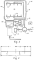
- FIG. 3 an alternative warewash machine embodiment is shown, which is of the box-type (also known as batch type or door type machines).
- the machine 140 includes a housing 142 defining a wash chamber 144 that is accessible by a door 146.
- the door may be pivotally mounted (e.g., in the case of an undercounter machine) or mounted for vertical, sliding movement (e.g., in the case of a hood-type machine). Wares are manually moved into the chamber 144 for cleaning, and manually removed when the cleaning cycle has been completed.
- a sump tank 148 is located below the chamber 144 and a pump 150 and line 152 are provided to deliver water from the sump to nozzles 154 of upper and lower spray arms 156 (e.g., of the rotating type).
- a detergent supply 158 and associated pump may be provided to deliver detergent to the sump 148 in a metered manner. Other forms of detergent supply may be used, such as manual placement of a block/solid type detergent product.
- a booster heater 162 receives water from a fresh water supply input 164 via a valve 166 or pump and has an output line 168 that delivers water to the nozzles 154 or, in the alternative, to a set of separate rinse arms with associated nozzles (not shown).
- a rinse aid supply 170 and associated pump 172 is provided to deliver rinse aid to the booster tank 162 in a metered manner.
- the sump 148 includes an associated drain outlet 174 that leads to a sensor assembly 108 (shown in dashed line form as a box) which could be similar to that of Fig. 2 .
- a drain valve 110 is provided to control draining, but a pumped drain line system could alternatively be provided.
- a controller 180 is provided to operate the various valves and pumps in accordance with one or more programmed cleaning cycles.
- Machine actions based on determined turbidity/soil level will generally be determined by the type and configuration of warewash machine with the goal of reducing the potential for soil re-deposition.
- the basic types of machines can be divided into two categories, the conveyor-type (e.g., per Fig.l) and the box-type (e.g., per Fig. 3 ).
- variables that can be controlled based on the soil level in the sump tank 148 include, by way of example: (1) frequency and duration of wash (e.g., by controlling the duration of operation of pump 150), (2) drop down duration (i.e., the dwell time between the spraying of detergent laden wash liquid and the subsequent spraying of clean rinse liquid; e.g., by controlling when the booster water is delivered following cessation of pump 150 operation), (3) frequency and duration of draining of the sump tank 148 (e.g, via control of valve 110), (4) rinse duration and/or rinse water volume (e.g., by controlling how long valve 166 is maintained open), (5) rinse aid dosing (e.g., by controlling operation of pump 172), (6) detergent dosing (e.g., by controlling operation of pump 160), (7) steam cycle (if available), (8) drying duration (e.g., by controlling operation of a blower and/or heating element used during drying), (9) interruption of the wash with a partial drain followed by refill and
- an exemplary cycle Tc is delineated by a wash period W (e.g., during which detergent laden liquid is recirculated), a drop down period DD during which recirculation of wash liquid stops and the machine dwells to allow liquid to drop down off of the ware and a rinse period R during which clean rinse liquid is sprayed on the wares.
- Two exemplary water sample times are shown at drain times D1 and D2.
- Sampling at D1 could primarily be used to determine whether to modify wash duration, drop down duration, timing of drain time D2, volume drained at drain time D2, rinse duration, rinse aid dosing and detergent dosing.
- Sampling a D2 could primarily be used to determine whether to modify drop down duration, introduction of a third drain time for sampling and its associated volume and rinse duration.
- conveyor-type machine variables that can be controlled based on the soil level in the monitored tank or tanks include, by way of example: (1) dilution of pre-wash (e.g., by controlling valve 76), (2) dilution of main wash (e.g., by controlling valve 78), (3) dilution of post wash (e.g., by controlling valve 80), (4) conveyor speed (e.g., by controlling a motor associated with the conveyor 12), (5) drain valves or drain pumps associated with the tanks, (6) final rinse flow rate (e.g., by controlling valve 56 or a pump associated with the rinse line), (7) wash flow rate (e.g., by controlling operation of pump 36), (8) frequency and duration of tank drains, (9) rinse aid dosing (e.g., by controlling operation of pump 92) and (10) detergent dosing (e.g., by controlling operation of pump 98.
- pre-wash e.g., by controlling valve 76
- main wash e.g., by controlling valve 78
- post wash
- a method is to inject clean water into the sensor may be provided and the sensor arrangement operated. If the light receiver voltage levels are not within a set tolerance and/or if the soil sensor assembly operation stops, an error message is given (e.g., via the controller 100 to energize a visual or audible annunciator). An error offset may allow for continued operation.
Landscapes
- Investigating Or Analysing Materials By Optical Means (AREA)
- Washing And Drying Of Tableware (AREA)
Claims (13)
- Machine à laver la vaisselle (10), comprenant :un réservoir (26 ; 34 ; 42 ; 148) destiné à contenir un liquide à pulvériser sur des articles dans une chambre de pulvérisation ;une conduite de recirculation (30 ; 38 ; 46 ; 152) destinée à distribuer le liquide du réservoir à des buses (32 ; 40 ; 48 ; 154) pour pulvérisation ;un agencement de capteur (108) destiné à surveiller l'état du liquide du réservoir, l'agencement de capteur comportant un émetteur de lumière (114) et un récepteur de lumière (116) et étant positionné à l'extérieur dudit réservoir ; etun dispositif de commande (100 ; 180) destiné à surveiller la sortie du récepteur de lumière (116),dans laquelle l'agencement de capteur (108) est positionné le long d'un chemin qui est une conduite de vidange (104) du réservoir, la conduite de vidange (104) étant raccordée à une sortie (106) du réservoir et conduisant à un écoulement de l'installation, ou une conduite (122) raccordée parallèlement à la conduite de vidange (104), caractérisée en ce que le dispositif de commande (100) est configuré pour effectuer une opération de surveillance du liquide au moyen dudit agencement de capteur (108) après que le déplacement du liquide le long du chemin s'est arrêté et qu'une période de sédimentation s'est écoulée, la période de sédimentation étant appliquée avant de déclencher l'agencement de capteur (108) pour surveillance.
- Machine de la revendication 1, dans laquelle :la machine est une machine de type caisson et la surveillance se produit (1) pendant une opération de lavage avec recirculation et/ou (2) pendant une période de repos suivant l'opération de lavage avec recirculation.
- Machine d'une des revendications 1 et 2, dans laquelle :la machine est une machine de type caisson et le dispositif de commande est configuré pour effectuer une ou plusieurs des opérations suivantes en fonction de la sortie de l'agencement de capteur : (i) fréquence et/ou durée de l'opération de lavage avec recirculation d'un cycle de nettoyage, (ii) durée de repos, (iii) fréquence et/ou durée de vidange du collecteur, (iv) durée de rinçage et/ou volume d'eau de rinçage, (v) niveau de dosage d'adjuvant de rinçage, (vi) niveau de dosage de détergent, (vii) cycle de vapeur, (viii) durée de séchage, (ix) interruption de l'opération de lavage avec recirculation d'un cycle de nettoyage avec une vidange partielle suivie d'un remplissage et poursuite de l'opération de lavage avec recirculation, et/ou (x) réalisation d'une vidange partielle ou totale après l'opération de lavage avec recirculation d'un cycle de nettoyage et répétition de l'opération de lavage avec recirculation du cycle de nettoyage avant rinçage.
- Machine de la revendication 1, dans laquelle :la machine est une machine de type convoyeur et le réservoir (26 ; 34 ; 42) est associé à une zone de prélavage (16), une zone de lavage (18) ou une zone de post-lavage (20) de la machine.
- Machine de la revendication 4, dans laquelle :le dispositif de commande (100) est configuré pour effectuer une ou plusieurs des opérations suivantes en fonction de la sortie de l'agencement de capteur : (i) dilution du liquide de prélavage, (ii) dilution du liquide de lavage principal, (iii) dilution du liquide de post-lavage, (iv) vitesse de transport, (v) vidange partielle ou totale du réservoir, (vi) débit de rinçage final, (vii) débit de lavage, (viii) dosage d'adjuvant de rinçage, et/ou (ix) dosage de détergent.
- Machine d'une des revendications précédentes, dans laquelle :le dispositif de commande (100 ; 180) évalue un ou plusieurs des paramètres suivants : (1) niveau de sortie discret du récepteur de lumière (116) à un ou plusieurs points temporels, (2) vitesse de changement du niveau de sortie du récepteur de lumière par rapport au temps, et/ou (3) variance du niveau de sortie du récepteur de lumière à l'intérieur d'un laps de temps établi.
- Machine d'une des revendications précédentes, dans laquelle :l'agencement de capteur (108) comporte des paires émetteur de lumière-récepteur de lumière espacées verticalement à différentes hauteurs dans une zone d'échantillonnage.
- Machine d'une des revendications précédentes, dans laquelle :l'agencement de capteur est constitué d'une structure de tube transparent (110) avec un module de détection (112) monté sur celle-ci, la structure de tube transparent formant une partie du chemin.
- Machine de la revendication 8, dans laquelle :l'émetteur de lumière (114) est positionné sur un côté de la structure de tube transparent (110) et le récepteur de lumière (116) est positionné sur un côté opposé de la structure de tube transparent.
- Machine d'une des revendications précédentes, dans laquelle :le dispositif de commande est configuré pour exciter l'émetteur de lumière de manière à produire une sortie d'intensité lumineuse variable depuis l'émetteur de lumière.
- Machine de la revendication 10, dans laquelle :le dispositif de commande (100 ; 180) est configuré pour exciter l'émetteur de lumière de manière à produire (i) une pluralité d'intensités lumineuses échelonnées ou (ii) une intensité lumineuse graduée.
- Procédé de détection de la souillure d'un liquide dans un réservoir d'une machine à laver la vaisselle, la machine à laver la vaisselle comprenant un tel réservoir (26 ; 34 ; 42 ; 148) pour contenir un liquide à pulvériser sur des articles dans une chambre de pulvérisation, une conduite de recirculation (30 ; 38 ; 46 ; 152) destinée à distribuer le liquide du réservoir à des buses (32 ; 40 ; 48 ; 154) pour pulvérisation, un agencement de capteur (108) positionné à l'extérieur dudit réservoir pour surveiller l'état du liquide du réservoir, l'agencement de capteur comportant un émetteur de lumière (114) et un récepteur de lumière (116), un dispositif de commande (100 ; 180) destiné à surveiller la sortie du récepteur de lumière (116) au moyen dudit agencement de capteur, le procédé comprenant les étapes consistant à :positionner l'agencement de capteur (108) le long d'un chemin qui est une conduite de vidange (104) du réservoir, la conduite de vidange (104) étant raccordée à une sortir (106) du réservoir et conduisant à un écoulement de l'installation, ou une conduite (122) raccordée parallèlement à la conduite de vidange (104) ;caractérisé en ce que le procédé comprend en outre :la réalisation d'une opération de surveillance du liquide à l'aide de l'agencement de capteur (108) après que le déplacement du liquide le long du chemin s'est arrêté et qu'une période de sédimentation s'est écoulée, la période de sédimentation étant appliquée avant de déclencher l'agencement de capteur (108) pour surveillance.
- Procédé de la revendication 12 dans lequel, pendant l'opération de surveillance du liquide, le dispositif de commande évalue un ou plusieurs des paramètres suivants : (1) niveau de sortie discret du récepteur de lumière à un ou plusieurs points temporels, (2) vitesse de changement du niveau de sortie du récepteur de lumière par rapport au temps, et/ou (3) variance du niveau de sortie du récepteur de lumière à l'intérieur d'un laps de temps établi.
Applications Claiming Priority (2)
| Application Number | Priority Date | Filing Date | Title |
|---|---|---|---|
| US12/604,992 US20110094544A1 (en) | 2009-10-23 | 2009-10-23 | Warewash machine with soil detection |
| PCT/US2010/052603 WO2011049806A1 (fr) | 2009-10-23 | 2010-10-14 | Machine pour laver des articles à détection de salissures et procédé de détection de salissures dans cette machine |
Publications (2)
| Publication Number | Publication Date |
|---|---|
| EP2490582A1 EP2490582A1 (fr) | 2012-08-29 |
| EP2490582B1 true EP2490582B1 (fr) | 2016-04-20 |
Family
ID=43629572
Family Applications (1)
| Application Number | Title | Priority Date | Filing Date |
|---|---|---|---|
| EP10774045.8A Not-in-force EP2490582B1 (fr) | 2009-10-23 | 2010-10-14 | Machine pour laver des articles à détection de salissures et procédé de détection de salissures dans cette machine |
Country Status (4)
| Country | Link |
|---|---|
| US (1) | US20110094544A1 (fr) |
| EP (1) | EP2490582B1 (fr) |
| CN (1) | CN102595994B (fr) |
| WO (1) | WO2011049806A1 (fr) |
Families Citing this family (31)
| Publication number | Priority date | Publication date | Assignee | Title |
|---|---|---|---|---|
| GB2489053A (en) * | 2011-03-18 | 2012-09-19 | Rockwash Prep & Store Ltd | A method and apparatus for washing rock samples |
| US9289107B2 (en) * | 2011-12-13 | 2016-03-22 | Ecolab Usa Inc. | Dishmachine |
| EP2664264B1 (fr) * | 2012-05-15 | 2021-03-10 | Electrolux Home Products Corporation N.V. | Procédé et dispositif de mesure de la turbidité |
| CN102974583A (zh) * | 2012-12-06 | 2013-03-20 | 深圳市华星光电技术有限公司 | 清洗方法和清洗系统 |
| CN103009657A (zh) * | 2012-12-06 | 2013-04-03 | 江苏海狮机械集团有限公司 | 压榨机中的漂洗装置 |
| DE102015203133B4 (de) | 2014-03-13 | 2020-02-06 | Illinois Tool Works Inc. | Spülmaschine in Gestalt einer als Programmautomat ausgebildeten gewerblichen Utensilien- oder Geschirrspülmaschine |
| CN104771128A (zh) * | 2015-03-26 | 2015-07-15 | 淮南东正电子科技有限公司 | 检测、除菌、清洗多功能一体器 |
| DE102015111994B4 (de) | 2015-07-23 | 2023-12-14 | Illinois Tool Works Inc. | Spülmaschine in Gestalt einer als Programmautomat ausgebildeten gewerblichen Utensilien- oder Geschirrspülmaschine |
| CN106908270A (zh) * | 2015-12-23 | 2017-06-30 | 台湾欧多贝斯股份有限公司 | 流体采样箱以及流体监测站 |
| DE102016107054A1 (de) * | 2016-04-15 | 2017-10-19 | Illinois Tool Works Inc. | Transportspülmaschine zum reinigen von spülgut |
| CN106539545A (zh) * | 2016-10-24 | 2017-03-29 | 佛山市顺德区美的洗涤电器制造有限公司 | 洗碗机及其控制方法 |
| CN106440161A (zh) * | 2016-11-03 | 2017-02-22 | 珠海格力电器股份有限公司 | 水箱组件及恒湿机 |
| CN108505281A (zh) * | 2017-02-24 | 2018-09-07 | 浙江工商职业技术学院 | 一种洗衣机的中止检测装置及方法 |
| CN107340725B (zh) * | 2017-03-29 | 2019-07-26 | 宁波方太厨具有限公司 | 一种清洗机的清洗控制方法 |
| CN107340724B (zh) * | 2017-03-29 | 2019-12-31 | 宁波方太厨具有限公司 | 一种清洗机的清洗控制方法 |
| TWM547943U (zh) * | 2017-05-22 | 2017-09-01 | 吉維那環保科技股份有限公司 | 洗滌機結構改良 |
| CN109793468A (zh) * | 2017-11-16 | 2019-05-24 | 青岛海尔洗碗机有限公司 | 一种洗碗机控制方法 |
| ES2717551B2 (es) * | 2017-12-21 | 2019-11-28 | Illinois Tool Works | Máquina lavavajillas de transportador provista de un dispositivo de aclarado mejorado y método asociado |
| US10952591B2 (en) | 2018-02-02 | 2021-03-23 | Dishcraft Robotics, Inc. | Intelligent dishwashing systems and methods |
| US11019980B2 (en) | 2018-08-24 | 2021-06-01 | Illinois Tool Works Inc. | Conveyor dishwashing machine, and method for operating a conveyor dishwashing machine |
| KR102699612B1 (ko) * | 2019-07-31 | 2024-08-26 | 엘지전자 주식회사 | 인공지능 로봇청소기 및 그를 포함하는 로봇 시스템 |
| CN111235810B (zh) * | 2020-01-07 | 2024-07-12 | 珠海格力电器股份有限公司 | 一种抽屉式洗涤装置及具有其的洗衣机 |
| JP6796224B1 (ja) * | 2020-02-20 | 2020-12-02 | 東京瓦斯株式会社 | 洗浄の方法、システム、プログラム、記録媒体および洗浄機器 |
| JP6796222B1 (ja) * | 2020-02-20 | 2020-12-02 | 東京瓦斯株式会社 | 洗浄の方法、システム、プログラム、記録媒体および洗浄機器 |
| CN111896354A (zh) * | 2020-08-31 | 2020-11-06 | 河南中烟工业有限责任公司 | 一种具有水质检测功能的浸梗机 |
| US20220061626A1 (en) * | 2020-09-02 | 2022-03-03 | Illinois Tool Works Inc. | Warewash machine drain down process and associated warewash machine |
| CN113368554A (zh) * | 2021-06-17 | 2021-09-10 | 珠海九通水务股份有限公司 | 排泥检测单元及水处理装置 |
| CN113580777B (zh) * | 2021-07-02 | 2022-08-12 | 福州大学 | 一种自动清洗喷墨打印喷头装置 |
| CN116106411A (zh) * | 2022-12-29 | 2023-05-12 | 山西钢科碳材料有限公司 | 一种水槽的控制装置及方法 |
| CN117966437B (zh) * | 2024-03-29 | 2024-06-04 | 苏州厨芯科技有限公司 | 一种洗涤装置的浊度检测方法及洗涤装置 |
| CN120940334B (zh) * | 2025-10-15 | 2025-12-12 | 天津市管道工程集团润源达供水设备科技有限公司 | 多水箱分隔式动态清洗系统及其自适应控制方法 |
Citations (1)
| Publication number | Priority date | Publication date | Assignee | Title |
|---|---|---|---|---|
| US20040216774A1 (en) * | 2003-04-29 | 2004-11-04 | Miele & Cie. Kg | Device for a turbidity sensor for a dishwasher or washing machine |
Family Cites Families (36)
| Publication number | Priority date | Publication date | Assignee | Title |
|---|---|---|---|---|
| CA1266385A (fr) * | 1985-01-08 | 1990-03-06 | Koji Kikuchi | Machine de lessivage a turbidimetre, et son fonctionnement |
| US5134867A (en) * | 1989-01-27 | 1992-08-04 | Matsushita Electric Industrial Co., Ltd. | Washing machine having optical sensor for detecting light permeability of detergent solution |
| JPH04319329A (ja) * | 1991-04-19 | 1992-11-10 | Mitsubishi Electric Corp | 排水濁度検知装置 |
| KR950011609B1 (ko) * | 1993-06-19 | 1995-10-06 | 엘지전자주식회사 | 세탁기의 세탁 제어방법과 장치 |
| US5586567A (en) * | 1995-01-10 | 1996-12-24 | General Electric Company | Dishwasher with turbidity sensing mechanism |
| US5560060A (en) * | 1995-01-10 | 1996-10-01 | General Electric Company | System and method for adjusting the operating cycle of a cleaning appliance |
| DE19521326A1 (de) * | 1995-06-12 | 1996-12-19 | Bosch Siemens Hausgeraete | Verfahren zur Temperaturkompensation der Meßwerte eines Trübungssensors in einer automatischen Wasch- oder Geschirrspülmaschine |
| US5803985A (en) * | 1996-03-13 | 1998-09-08 | Eaton Corporation | Water fill sensing for a dishwasher |
| US5596408A (en) * | 1996-05-07 | 1997-01-21 | Honeywell Inc. | Turbidity sensor with replaceable covers |
| US5729025A (en) * | 1996-07-09 | 1998-03-17 | Honeywell Inc. | Electromechanically actuated turbidity sensor for a machine for washing articles |
| US5800628A (en) * | 1996-10-22 | 1998-09-01 | Honeywell Inc. | Continuous cycle operation for dishwashers using turbidity sensor feedback |
| US5731868A (en) * | 1997-02-06 | 1998-03-24 | Honeywell Inc | Method for characterizing the nature of fluid in machine for washing articles |
| DE19721976B4 (de) * | 1997-05-26 | 2008-07-24 | BSH Bosch und Siemens Hausgeräte GmbH | Verfahren zum Feststellen eines unzulässig hohen Verkalkungsgrades in einem wasserführenden Haushaltsgerät |
| US5923432A (en) * | 1997-12-18 | 1999-07-13 | Steris Corporation | Cleaning efficacy real time indicator |
| DE19806559B4 (de) * | 1998-02-17 | 2015-10-29 | BSH Hausgeräte GmbH | Verfahren und Vorrichtung zur Behandlung von Geschirr in Spülmaschinen |
| US5957144A (en) * | 1998-05-18 | 1999-09-28 | Maytag Corporation | Turbidity sensor that interrupts drain motor and water valve |
| DE19831688C1 (de) * | 1998-07-15 | 2000-04-06 | Whirlpool Co | Optischer Sensor |
| DE19904280B4 (de) * | 1999-02-03 | 2005-08-18 | BSH Bosch und Siemens Hausgeräte GmbH | Vorrichtung und Verfahren zur Ermittlung von Ablagerungen an Glasoberflächen in Spülmaschinen |
| US6432216B1 (en) * | 2000-02-09 | 2002-08-13 | Whirlpool Corporation | Soil sensing system for a dishwasher |
| DE10135191A1 (de) * | 2001-07-19 | 2003-01-30 | Bsh Bosch Siemens Hausgeraete | Verfahren zum Betreiben eines wasserführenden Haushaltgerätes und Haushaltgerät hierzu |
| US6544344B2 (en) * | 2001-07-27 | 2003-04-08 | General Electric Company | Dishwasher including a turbidity sensor |
| DE50210345D1 (de) * | 2002-01-31 | 2007-08-02 | Emz Hanauer Gmbh & Co Kgaa | Trübungssensor mit Temperaturerfassung für Haushaltsgeräte |
| US20030196278A1 (en) * | 2002-04-19 | 2003-10-23 | Durfee Anthony L. | Static and dynamic turbidity sensing in a washing appliance |
| US7241347B2 (en) * | 2002-07-02 | 2007-07-10 | Whirlpool Corporation | Adaptive drain and purge system for a dishwasher |
| DE10253009B3 (de) * | 2002-11-14 | 2004-04-08 | Whirlpool Corp., Benton Harbor | Verfahren zum Betrieb einer Geschirrspülmaschine |
| DE10253025B3 (de) * | 2002-11-14 | 2004-07-22 | Whirlpool Corp., Benton Harbor | Verfahren zum Betreiben einer Geschirrspülmaschine mit zentraler Steuereinheit und Trübungsmessung |
| US7165896B2 (en) * | 2004-02-12 | 2007-01-23 | Hymite A/S | Light transmitting modules with optical power monitoring |
| DE102004030014A1 (de) * | 2004-06-22 | 2006-01-12 | Premark Feg L.L.C., Wilmington | Spülmaschinen-Betriebsverfahren und Transportspülmaschine |
| KR20060010361A (ko) * | 2004-07-28 | 2006-02-02 | 엘지전자 주식회사 | 식기 세척기의 탁도 센서 장착 구조 |
| KR20060024597A (ko) * | 2004-09-14 | 2006-03-17 | 엘지전자 주식회사 | 식기세척기의 구조 |
| US7082959B1 (en) * | 2006-03-21 | 2006-08-01 | Franklin Robert C | Shutoff valve system with leak detector |
| KR20080050834A (ko) * | 2006-12-04 | 2008-06-10 | 삼성전자주식회사 | 식기세척기의 세척제어장치 및 그 방법 |
| KR20080051369A (ko) * | 2006-12-05 | 2008-06-11 | 삼성전자주식회사 | 식기세척기의 세척제어장치 및 그 방법 |
| KR20090098453A (ko) * | 2008-03-14 | 2009-09-17 | 삼성전자주식회사 | 탁도센서와 이를 갖는 가전기기 |
| JP5157588B2 (ja) * | 2008-03-31 | 2013-03-06 | パナソニック株式会社 | 食器洗い機 |
| JP4909391B2 (ja) * | 2009-08-25 | 2012-04-04 | パナソニック株式会社 | 洗濯機 |
-
2009
- 2009-10-23 US US12/604,992 patent/US20110094544A1/en not_active Abandoned
-
2010
- 2010-10-14 EP EP10774045.8A patent/EP2490582B1/fr not_active Not-in-force
- 2010-10-14 WO PCT/US2010/052603 patent/WO2011049806A1/fr not_active Ceased
- 2010-10-14 CN CN201080046781.8A patent/CN102595994B/zh not_active Expired - Fee Related
Patent Citations (1)
| Publication number | Priority date | Publication date | Assignee | Title |
|---|---|---|---|---|
| US20040216774A1 (en) * | 2003-04-29 | 2004-11-04 | Miele & Cie. Kg | Device for a turbidity sensor for a dishwasher or washing machine |
Also Published As
| Publication number | Publication date |
|---|---|
| US20110094544A1 (en) | 2011-04-28 |
| CN102595994A (zh) | 2012-07-18 |
| CN102595994B (zh) | 2015-11-25 |
| WO2011049806A1 (fr) | 2011-04-28 |
| EP2490582A1 (fr) | 2012-08-29 |
Similar Documents
| Publication | Publication Date | Title |
|---|---|---|
| US20110094544A1 (en) | Warewash machine with soil detection | |
| US20120298146A1 (en) | Warewash machine with soil detection | |
| JP2004154576A (ja) | 物品洗浄器の洗浄サイクルを制御して水位を検出して物品洗浄器の化学薬品送りラインを装填する、システム及び方法 | |
| CN102123647B (zh) | 传送式洗碗机以及操作传送式洗碗机的方法 | |
| CN102119059B (zh) | 传送式洗碗机和操作传送式洗碗机的方法 | |
| US8038802B1 (en) | Reuse of wash liquid in dishwasher | |
| CN109936994B (zh) | 用于清洁待清洁物品的方法和清洁设备 | |
| EP2744385B1 (fr) | Lave-vaisselle et procédé permettant de nettoyer automatiquement un lave-vaisselle | |
| JPH09510647A (ja) | 濁度検知機構を有する皿洗い機 | |
| US9420937B2 (en) | Dishwasher with dynamically controlled cycle of operation | |
| AU2019201764B2 (en) | Conveyor dishwasher | |
| EP2296519B1 (fr) | Procede de fonctionnement d'un lave-vaisselle et lave-vaisselle | |
| KR20100037456A (ko) | 식기 세척기의 제어방법 | |
| CN109068932B (zh) | 用于清洗待洗器皿的传送式洗碗机 | |
| US8968483B2 (en) | Method of using liquid in a dishwasher | |
| EP3826521B1 (fr) | Lave-vaisselle commercial comprenant un système pour déterminer la consommation d'eau douce par le lave-vaisselle | |
| EP3469977B1 (fr) | Procédé de sélection d'opération de lavage pour un lave-vaisselle | |
| KR0171517B1 (ko) | 식기세척기의 세제량투입결정방법 | |
| KR20210087213A (ko) | 식기 세척기 및 식기 세척기의 제어방법 | |
| HK40010648A (en) | Method and cleaning device for cleaning items to be cleaned | |
| HK40010648B (en) | Method and cleaning device for cleaning items to be cleaned |
Legal Events
| Date | Code | Title | Description |
|---|---|---|---|
| PUAI | Public reference made under article 153(3) epc to a published international application that has entered the european phase |
Free format text: ORIGINAL CODE: 0009012 |
|
| 17P | Request for examination filed |
Effective date: 20120413 |
|
| AK | Designated contracting states |
Kind code of ref document: A1 Designated state(s): AL AT BE BG CH CY CZ DE DK EE ES FI FR GB GR HR HU IE IS IT LI LT LU LV MC MK MT NL NO PL PT RO RS SE SI SK SM TR |
|
| DAX | Request for extension of the european patent (deleted) | ||
| 17Q | First examination report despatched |
Effective date: 20141024 |
|
| GRAP | Despatch of communication of intention to grant a patent |
Free format text: ORIGINAL CODE: EPIDOSNIGR1 |
|
| RIC1 | Information provided on ipc code assigned before grant |
Ipc: D06F 39/00 20060101ALI20151210BHEP Ipc: D06F 33/02 20060101ALI20151210BHEP Ipc: A47L 15/24 20060101ALN20151210BHEP Ipc: A47L 15/42 20060101AFI20151210BHEP |
|
| INTG | Intention to grant announced |
Effective date: 20160114 |
|
| GRAS | Grant fee paid |
Free format text: ORIGINAL CODE: EPIDOSNIGR3 |
|
| GRAA | (expected) grant |
Free format text: ORIGINAL CODE: 0009210 |
|
| AK | Designated contracting states |
Kind code of ref document: B1 Designated state(s): AL AT BE BG CH CY CZ DE DK EE ES FI FR GB GR HR HU IE IS IT LI LT LU LV MC MK MT NL NO PL PT RO RS SE SI SK SM TR |
|
| REG | Reference to a national code |
Ref country code: GB Ref legal event code: FG4D |
|
| REG | Reference to a national code |
Ref country code: CH Ref legal event code: EP |
|
| REG | Reference to a national code |
Ref country code: AT Ref legal event code: REF Ref document number: 791422 Country of ref document: AT Kind code of ref document: T Effective date: 20160515 |
|
| REG | Reference to a national code |
Ref country code: IE Ref legal event code: FG4D |
|
| REG | Reference to a national code |
Ref country code: DE Ref legal event code: R096 Ref document number: 602010032565 Country of ref document: DE |
|
| REG | Reference to a national code |
Ref country code: DK Ref legal event code: T3 Effective date: 20160801 |
|
| REG | Reference to a national code |
Ref country code: SE Ref legal event code: TRGR |
|
| REG | Reference to a national code |
Ref country code: NL Ref legal event code: FP |
|
| REG | Reference to a national code |
Ref country code: LT Ref legal event code: MG4D |
|
| REG | Reference to a national code |
Ref country code: AT Ref legal event code: MK05 Ref document number: 791422 Country of ref document: AT Kind code of ref document: T Effective date: 20160420 |
|
| REG | Reference to a national code |
Ref country code: FR Ref legal event code: PLFP Year of fee payment: 7 |
|
| PG25 | Lapsed in a contracting state [announced via postgrant information from national office to epo] |
Ref country code: PL Free format text: LAPSE BECAUSE OF FAILURE TO SUBMIT A TRANSLATION OF THE DESCRIPTION OR TO PAY THE FEE WITHIN THE PRESCRIBED TIME-LIMIT Effective date: 20160420 Ref country code: NO Free format text: LAPSE BECAUSE OF FAILURE TO SUBMIT A TRANSLATION OF THE DESCRIPTION OR TO PAY THE FEE WITHIN THE PRESCRIBED TIME-LIMIT Effective date: 20160720 Ref country code: FI Free format text: LAPSE BECAUSE OF FAILURE TO SUBMIT A TRANSLATION OF THE DESCRIPTION OR TO PAY THE FEE WITHIN THE PRESCRIBED TIME-LIMIT Effective date: 20160420 Ref country code: LT Free format text: LAPSE BECAUSE OF FAILURE TO SUBMIT A TRANSLATION OF THE DESCRIPTION OR TO PAY THE FEE WITHIN THE PRESCRIBED TIME-LIMIT Effective date: 20160420 |
|
| PG25 | Lapsed in a contracting state [announced via postgrant information from national office to epo] |
Ref country code: ES Free format text: LAPSE BECAUSE OF FAILURE TO SUBMIT A TRANSLATION OF THE DESCRIPTION OR TO PAY THE FEE WITHIN THE PRESCRIBED TIME-LIMIT Effective date: 20160420 Ref country code: LV Free format text: LAPSE BECAUSE OF FAILURE TO SUBMIT A TRANSLATION OF THE DESCRIPTION OR TO PAY THE FEE WITHIN THE PRESCRIBED TIME-LIMIT Effective date: 20160420 Ref country code: GR Free format text: LAPSE BECAUSE OF FAILURE TO SUBMIT A TRANSLATION OF THE DESCRIPTION OR TO PAY THE FEE WITHIN THE PRESCRIBED TIME-LIMIT Effective date: 20160721 Ref country code: RS Free format text: LAPSE BECAUSE OF FAILURE TO SUBMIT A TRANSLATION OF THE DESCRIPTION OR TO PAY THE FEE WITHIN THE PRESCRIBED TIME-LIMIT Effective date: 20160420 Ref country code: HR Free format text: LAPSE BECAUSE OF FAILURE TO SUBMIT A TRANSLATION OF THE DESCRIPTION OR TO PAY THE FEE WITHIN THE PRESCRIBED TIME-LIMIT Effective date: 20160420 Ref country code: AT Free format text: LAPSE BECAUSE OF FAILURE TO SUBMIT A TRANSLATION OF THE DESCRIPTION OR TO PAY THE FEE WITHIN THE PRESCRIBED TIME-LIMIT Effective date: 20160420 Ref country code: PT Free format text: LAPSE BECAUSE OF FAILURE TO SUBMIT A TRANSLATION OF THE DESCRIPTION OR TO PAY THE FEE WITHIN THE PRESCRIBED TIME-LIMIT Effective date: 20160822 |
|
| PG25 | Lapsed in a contracting state [announced via postgrant information from national office to epo] |
Ref country code: BE Free format text: LAPSE BECAUSE OF FAILURE TO SUBMIT A TRANSLATION OF THE DESCRIPTION OR TO PAY THE FEE WITHIN THE PRESCRIBED TIME-LIMIT Effective date: 20160420 |
|
| REG | Reference to a national code |
Ref country code: DE Ref legal event code: R097 Ref document number: 602010032565 Country of ref document: DE |
|
| PG25 | Lapsed in a contracting state [announced via postgrant information from national office to epo] |
Ref country code: RO Free format text: LAPSE BECAUSE OF FAILURE TO SUBMIT A TRANSLATION OF THE DESCRIPTION OR TO PAY THE FEE WITHIN THE PRESCRIBED TIME-LIMIT Effective date: 20160420 Ref country code: SK Free format text: LAPSE BECAUSE OF FAILURE TO SUBMIT A TRANSLATION OF THE DESCRIPTION OR TO PAY THE FEE WITHIN THE PRESCRIBED TIME-LIMIT Effective date: 20160420 Ref country code: EE Free format text: LAPSE BECAUSE OF FAILURE TO SUBMIT A TRANSLATION OF THE DESCRIPTION OR TO PAY THE FEE WITHIN THE PRESCRIBED TIME-LIMIT Effective date: 20160420 Ref country code: CZ Free format text: LAPSE BECAUSE OF FAILURE TO SUBMIT A TRANSLATION OF THE DESCRIPTION OR TO PAY THE FEE WITHIN THE PRESCRIBED TIME-LIMIT Effective date: 20160420 |
|
| PLBE | No opposition filed within time limit |
Free format text: ORIGINAL CODE: 0009261 |
|
| STAA | Information on the status of an ep patent application or granted ep patent |
Free format text: STATUS: NO OPPOSITION FILED WITHIN TIME LIMIT |
|
| PG25 | Lapsed in a contracting state [announced via postgrant information from national office to epo] |
Ref country code: SM Free format text: LAPSE BECAUSE OF FAILURE TO SUBMIT A TRANSLATION OF THE DESCRIPTION OR TO PAY THE FEE WITHIN THE PRESCRIBED TIME-LIMIT Effective date: 20160420 |
|
| 26N | No opposition filed |
Effective date: 20170123 |
|
| PG25 | Lapsed in a contracting state [announced via postgrant information from national office to epo] |
Ref country code: SI Free format text: LAPSE BECAUSE OF FAILURE TO SUBMIT A TRANSLATION OF THE DESCRIPTION OR TO PAY THE FEE WITHIN THE PRESCRIBED TIME-LIMIT Effective date: 20160420 |
|
| REG | Reference to a national code |
Ref country code: CH Ref legal event code: PL |
|
| REG | Reference to a national code |
Ref country code: IE Ref legal event code: MM4A |
|
| PG25 | Lapsed in a contracting state [announced via postgrant information from national office to epo] |
Ref country code: LI Free format text: LAPSE BECAUSE OF NON-PAYMENT OF DUE FEES Effective date: 20161031 Ref country code: CH Free format text: LAPSE BECAUSE OF NON-PAYMENT OF DUE FEES Effective date: 20161031 |
|
| PG25 | Lapsed in a contracting state [announced via postgrant information from national office to epo] |
Ref country code: LU Free format text: LAPSE BECAUSE OF NON-PAYMENT OF DUE FEES Effective date: 20161014 |
|
| REG | Reference to a national code |
Ref country code: FR Ref legal event code: PLFP Year of fee payment: 8 |
|
| PG25 | Lapsed in a contracting state [announced via postgrant information from national office to epo] |
Ref country code: IE Free format text: LAPSE BECAUSE OF NON-PAYMENT OF DUE FEES Effective date: 20161014 |
|
| PG25 | Lapsed in a contracting state [announced via postgrant information from national office to epo] |
Ref country code: HU Free format text: LAPSE BECAUSE OF FAILURE TO SUBMIT A TRANSLATION OF THE DESCRIPTION OR TO PAY THE FEE WITHIN THE PRESCRIBED TIME-LIMIT; INVALID AB INITIO Effective date: 20101014 Ref country code: CY Free format text: LAPSE BECAUSE OF FAILURE TO SUBMIT A TRANSLATION OF THE DESCRIPTION OR TO PAY THE FEE WITHIN THE PRESCRIBED TIME-LIMIT Effective date: 20160420 |
|
| PG25 | Lapsed in a contracting state [announced via postgrant information from national office to epo] |
Ref country code: MT Free format text: LAPSE BECAUSE OF NON-PAYMENT OF DUE FEES Effective date: 20161031 Ref country code: MK Free format text: LAPSE BECAUSE OF FAILURE TO SUBMIT A TRANSLATION OF THE DESCRIPTION OR TO PAY THE FEE WITHIN THE PRESCRIBED TIME-LIMIT Effective date: 20160420 Ref country code: IS Free format text: LAPSE BECAUSE OF FAILURE TO SUBMIT A TRANSLATION OF THE DESCRIPTION OR TO PAY THE FEE WITHIN THE PRESCRIBED TIME-LIMIT Effective date: 20160420 Ref country code: TR Free format text: LAPSE BECAUSE OF FAILURE TO SUBMIT A TRANSLATION OF THE DESCRIPTION OR TO PAY THE FEE WITHIN THE PRESCRIBED TIME-LIMIT Effective date: 20160420 Ref country code: MC Free format text: LAPSE BECAUSE OF FAILURE TO SUBMIT A TRANSLATION OF THE DESCRIPTION OR TO PAY THE FEE WITHIN THE PRESCRIBED TIME-LIMIT Effective date: 20160420 |
|
| PG25 | Lapsed in a contracting state [announced via postgrant information from national office to epo] |
Ref country code: BG Free format text: LAPSE BECAUSE OF FAILURE TO SUBMIT A TRANSLATION OF THE DESCRIPTION OR TO PAY THE FEE WITHIN THE PRESCRIBED TIME-LIMIT Effective date: 20160420 |
|
| REG | Reference to a national code |
Ref country code: FR Ref legal event code: PLFP Year of fee payment: 9 |
|
| PG25 | Lapsed in a contracting state [announced via postgrant information from national office to epo] |
Ref country code: AL Free format text: LAPSE BECAUSE OF FAILURE TO SUBMIT A TRANSLATION OF THE DESCRIPTION OR TO PAY THE FEE WITHIN THE PRESCRIBED TIME-LIMIT Effective date: 20160420 |
|
| PGFP | Annual fee paid to national office [announced via postgrant information from national office to epo] |
Ref country code: NL Payment date: 20201026 Year of fee payment: 11 |
|
| PGFP | Annual fee paid to national office [announced via postgrant information from national office to epo] |
Ref country code: IT Payment date: 20201023 Year of fee payment: 11 Ref country code: FR Payment date: 20201026 Year of fee payment: 11 Ref country code: SE Payment date: 20201028 Year of fee payment: 11 Ref country code: GB Payment date: 20201027 Year of fee payment: 11 Ref country code: DK Payment date: 20201028 Year of fee payment: 11 Ref country code: DE Payment date: 20201028 Year of fee payment: 11 |
|
| REG | Reference to a national code |
Ref country code: DE Ref legal event code: R119 Ref document number: 602010032565 Country of ref document: DE |
|
| REG | Reference to a national code |
Ref country code: DK Ref legal event code: EBP Effective date: 20211031 |
|
| REG | Reference to a national code |
Ref country code: SE Ref legal event code: EUG |
|
| REG | Reference to a national code |
Ref country code: NL Ref legal event code: MM Effective date: 20211101 |
|
| GBPC | Gb: european patent ceased through non-payment of renewal fee |
Effective date: 20211014 |
|
| PG25 | Lapsed in a contracting state [announced via postgrant information from national office to epo] |
Ref country code: SE Free format text: LAPSE BECAUSE OF NON-PAYMENT OF DUE FEES Effective date: 20211015 Ref country code: NL Free format text: LAPSE BECAUSE OF NON-PAYMENT OF DUE FEES Effective date: 20211101 Ref country code: GB Free format text: LAPSE BECAUSE OF NON-PAYMENT OF DUE FEES Effective date: 20211014 Ref country code: DE Free format text: LAPSE BECAUSE OF NON-PAYMENT OF DUE FEES Effective date: 20220503 |
|
| PG25 | Lapsed in a contracting state [announced via postgrant information from national office to epo] |
Ref country code: FR Free format text: LAPSE BECAUSE OF NON-PAYMENT OF DUE FEES Effective date: 20211031 |
|
| PG25 | Lapsed in a contracting state [announced via postgrant information from national office to epo] |
Ref country code: IT Free format text: LAPSE BECAUSE OF NON-PAYMENT OF DUE FEES Effective date: 20211014 Ref country code: DK Free format text: LAPSE BECAUSE OF NON-PAYMENT OF DUE FEES Effective date: 20211031 |