EP2491982A2 - Rideau coupe-feu destiné à fermer une ouverture de bâtiment et procédé correspondant - Google Patents
Rideau coupe-feu destiné à fermer une ouverture de bâtiment et procédé correspondant Download PDFInfo
- Publication number
- EP2491982A2 EP2491982A2 EP12000815A EP12000815A EP2491982A2 EP 2491982 A2 EP2491982 A2 EP 2491982A2 EP 12000815 A EP12000815 A EP 12000815A EP 12000815 A EP12000815 A EP 12000815A EP 2491982 A2 EP2491982 A2 EP 2491982A2
- Authority
- EP
- European Patent Office
- Prior art keywords
- fire
- zone
- elasticity
- fire protection
- protection element
- Prior art date
- Legal status (The legal status is an assumption and is not a legal conclusion. Google has not performed a legal analysis and makes no representation as to the accuracy of the status listed.)
- Withdrawn
Links
- 239000000779 smoke Substances 0.000 title claims abstract description 39
- 238000000034 method Methods 0.000 title claims abstract description 4
- 239000004753 textile Substances 0.000 claims description 24
- 238000004804 winding Methods 0.000 claims description 13
- 230000007547 defect Effects 0.000 claims 1
- 238000009941 weaving Methods 0.000 claims 1
- 239000004744 fabric Substances 0.000 abstract description 4
- 230000001681 protective effect Effects 0.000 abstract description 2
- 230000008901 benefit Effects 0.000 description 4
- 230000002349 favourable effect Effects 0.000 description 3
- 239000000463 material Substances 0.000 description 3
- 238000004519 manufacturing process Methods 0.000 description 2
- 239000000155 melt Substances 0.000 description 2
- RNFJDJUURJAICM-UHFFFAOYSA-N 2,2,4,4,6,6-hexaphenoxy-1,3,5-triaza-2$l^{5},4$l^{5},6$l^{5}-triphosphacyclohexa-1,3,5-triene Chemical compound N=1P(OC=2C=CC=CC=2)(OC=2C=CC=CC=2)=NP(OC=2C=CC=CC=2)(OC=2C=CC=CC=2)=NP=1(OC=1C=CC=CC=1)OC1=CC=CC=C1 RNFJDJUURJAICM-UHFFFAOYSA-N 0.000 description 1
- 239000012141 concentrate Substances 0.000 description 1
- 230000005611 electricity Effects 0.000 description 1
- 239000003063 flame retardant Substances 0.000 description 1
- 239000003779 heat-resistant material Substances 0.000 description 1
- 238000010606 normalization Methods 0.000 description 1
Images


Classifications
-
- A—HUMAN NECESSITIES
- A62—LIFE-SAVING; FIRE-FIGHTING
- A62C—FIRE-FIGHTING
- A62C2/00—Fire prevention or containment
- A62C2/06—Physical fire-barriers
- A62C2/10—Fire-proof curtains
-
- E—FIXED CONSTRUCTIONS
- E06—DOORS, WINDOWS, SHUTTERS, OR ROLLER BLINDS IN GENERAL; LADDERS
- E06B—FIXED OR MOVABLE CLOSURES FOR OPENINGS IN BUILDINGS, VEHICLES, FENCES OR LIKE ENCLOSURES IN GENERAL, e.g. DOORS, WINDOWS, BLINDS, GATES
- E06B9/00—Screening or protective devices for wall or similar openings, with or without operating or securing mechanisms; Closures of similar construction
- E06B9/24—Screens or other constructions affording protection against light, especially against sunshine; Similar screens for privacy or appearance; Slat blinds
- E06B9/40—Roller blinds
- E06B9/42—Parts or details of roller blinds, e.g. suspension devices, blind boxes
Definitions
- the invention relates to a fire or smoke protection curtain for closing a building opening, comprising (a) a flexible fire protection element comprising a fire protection textile, and (b) a finishing strip closing the fire protection element.
- Such a fire or smoke protection curtain is from the EP 0 906 772 A2 known.
- Such fire and smoke curtains are mounted on site on the building by the flexible smoke protection element is attached, for example, to a winding shaft. Thereafter, the fire protection element is wound onto the winding shaft until the end strip is flush with the ceiling. If the flexible fire protection element, in particular the fire protection textile, has not been perfectly fastened to the winding shaft, one end of the end strip reaches the building ceiling earlier than the opposite one. The remaining gap is aesthetically undesirable.
- the end strip in two parts form, with a foot part of the end bar is resiliently connected to a headboard.
- a fire protection curtain which has a textile fabric with locally different elasticities. This ensures that internal pockets can expand in case of fire. However, the elasticity of the fire protection curtain as a whole is not affected, so that a classic end strip is still provided.
- the invention is based, to reduce the manufacturing cost of the end strip the task.
- the invention solves the problem by a fire or smoke protection curtain having the features of claim 1, a fire protection device having the features of claim 9 and a method having the features of claim 10.
- An advantage of the invention is that mounting errors can be compensated as in known systems without a specially gestatlete end strip would have to be provided. It is also advantageous that existing fire or smoke curtains can be retrofitted, if it has been found that there is a mounting error, so that the end strip is not flush with the system.
- the flexible fire protection element is understood in particular to mean an element which withstands a fire for at least 60 minutes. It should be noted that a flexible fire protection element is not necessarily elastic and in known fire or smoke curtains the fire protection element is also flexible, but not elastic. A flexible fire protection element is understood to mean a bendable fire protection element.
- an elongated component is understood, which is usually mounted below the fire protection element. If the fire or smoke protection curtain is placed in its closure arrangement in which the fire protection element closes the building opening, the end strip rests on the floor.
- the elasticity namely the inner-zone elasticity and the extra-zone elasticity, is understood in particular to be the quotient, the relative change in length as a numerator and the product of the force required to produce the elongation and the width.
- the elasticity zone can extend completely, so over the full width of the fire protection element, but that is not necessary. So is quite possible that an edge of the fire protection element no elasticity zone is present. It is particularly favorable, however, when the elasticity zone extends completely over the full width of the fire protection element.
- the elasticity zone can also be formed within the end strip. This is to be understood in particular that the elasticity zone is at least partially hidden by the end strip. However, the elasticity zone can also be formed at least partially outside the end strip.
- the elasticity zone has an elastic zone width measured perpendicular to the direction of the end strip, the elastic zone width being at most one fifth of a full height of the fire protection element.
- the inner zone elasticity is at least three times, in particular five times, the extra-zone elasticity.
- the advantage of this is that then concentrates a possible deformation of the fire protection element in the elasticity zone.
- the elasticity zone is formed by the fact that the fire protection textile forms at least one bulge extending along the end strip, which is held by means of an elastic fastening means.
- the bulge may in particular be a loop or gathering. This has the advantage that the flexible fire protection element over its entire length or height can be constructed substantially similar, which makes the production easier.
- the elastic fastening means is attached to the fire protection textile at at least two mutually horizontally spaced locations, so that forms an at least substantially horizontally extending bulge.
- the weight of the end strips is then at least predominantly absorbed by the elastic fastening means, so that the possible assembly errors are compensated by the elastic fastening means.
- the elastic fastening means comprises at least one spring element.
- the spring element is a spring, for example a metallic spring, or a rubber-elastic element, for example a rubber strip.
- the elastic fastening means is not resistant to heat.
- the elastic fastening means is then destroyed, so that the fire protection element can fully develop its protective effect by, for example, the bulge dissolves. It can then create a bulge that provides the necessary Deflekti-on.
- the elastic fastening means is flame retardant, incombustible and / or thermally resistant, so that it does not ignite even in a 90 minute fire test, when it is located on the side facing away from the fire.
- the elastic fastening means melts or softens under the action of fire heat.
- the elastic fastening means is covered by a heat-protected cover.
- the cover is formed by a part of the end strip.
- the fire or smoke protection curtain has a piping, which, for example by means of a fastener, with the end strip, in particular rigidly connected, wherein the elasticity zone extends at least also adjacent to the piping.
- the fire protection element rests at least also and at least partially with its elasticity zone on the piping.
- the elasticity zone may be formed by the fire protection textile having a different weave pattern in the elasticity zone than outside. It is known that the elasticity of fire protection textiles with respect to a given direction depends on the course of the weave pattern with respect to this direction and the weave pattern itself. Through targeted changes of the weave pattern, the elasticity can be changed locally.
- the recording has a system, in particular a veneer or a stop, wherein arranged in the bearing assembly in which the fire protection element in the recording is, the end strip rests along its longitudinal extension of the plant and a possible misalignment of the end strip is compensated by the elasticity zone.
- the veneer is understood in particular to mean a component which is at least partially visible when the fire protection element is in its bearing arrangement and which interacts with the end strip in such a way that the fire protection element in the bearing arrangement attracts as little attention as possible.
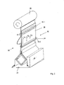
- FIG. 1 shows a fire or smoke curtain 10 for closing a building opening 12, such as a passage, a gate opening, a window or the like.
- the fire or smoke protection curtain 10 comprises a flexible fire protection element 14, which has a fire protection textile 16, and a final strip 18 which terminates the fire protection element 14 downwards.
- the end strip 18 comprises a piping 20, which is looped around by the fire protection textile 16, and a head part 22, which is held by means of the welt 20, and a foot part 24, which is held by the head part 22.
- the foot part 24 surrounds the head part 22.
- FIG. 1 also shows a winding roll 26 on which the fire protection fabric 16 is wound to bring it into its storage arrangement.
- closure assembly is the end strip 18 with its foot 24 to a system 28, which is formed in the present case as a veneer and defines a slot 29 through which the fire protection element 16 runs when it is wound onto the winding roller 26.
- EB is the electricity zone width
- ⁇ l (cf. FIG. 2 )
- the width B serves as normalization, so that the elasticity does not depend on the width of the considered fire protection element 14.
- ⁇ l / ER is the relative elongation.
- FIG. 1 shows the case without assembly error, in which the end strip 18 simultaneously abuts with its foot part 24 over its full length to the system 28 when the fire protection element 14 is wound onto the winding roller 26.
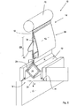
- FIG. 2 shows the case in which the system 28 has a mounting error, so that the in FIG. 2 front end of the foot part 24, the system 28 reached earlier than that in FIG. 2 drawn on the back. If the winding roll 26 is rotated further, the fire protection element 14 elongates in the elasticity zone 30, as indicated by the arrows P1, P2 and P3, locally different. Finally, if that too in FIG. 2 rear end of the foot part 24 rests against the system 28, close the end bar 18 and the system 28 flush with each other, although it has come to a mounting error.
- FIG. 2 shows that the elastic zone 30 is formed by the fact that the fire protection textile 16 forms a bulge 32 extending along the end strip 18, which is held by means of an elastic fastening means 34.
- the elastic fastening means 34 comprises, for example, a spring element 36 in the form of at least one rubber-elastic strip which is fastened to the fire protection textile 16 by fixing elements 38.1, 38.2.
- the spring element 36 may, as in the present case, from a non-heat-resistant material, such as rubber, so that it dissolves in the event of fire. If the fire protection element 14 has multiple layers of fire protection textile 16, between which, for example, intumescent material is arranged, then this intumescent material can expand unhindered, since it is no longer prevented by the elastic fastening means 34 therefrom.
- the fixing elements 38 reference numerals without counting suffix designate the object as such
- FIG. 3 shows a further embodiment of a fire or smoke protection curtain 10 according to the invention, in which the elastic fastening means 34 is formed by a plurality of threads that hold a gathering 38 of the fire protection textile 16.
- the threads are also elastic, so the possible assembly errors, as exemplified in FIG. 2 shown can be compensated.
- FIGS. 1 and 2 is also with the fire or smoke protection curtain 10 according to FIG. 3 the fire protection textile 16 also formed in the elastic zone 30 throughout.
- FIG. 4 shows an embodiment of a fire or smoke protection curtain 10 according to the invention, in which the fire protection textile 16 is interrupted, wherein the elastic fastening means 34 bridges the resulting gap.
- the fire protection element 14 has a zone of elasticity 30 which has a zone of elasticity EB.
- a height H of the fire protection element 14 is shown, which corresponds to the distance between the uppermost part of the fire protection element 14, which is in particular attached to the winding roll 26 and the lower end of the fire protection element 14 which is attached to the end strip 18.
- the elasticity zone width EB is significantly smaller than the size H, for example, it is less than one third, in particular less than one fifth of the height H.
- the elasticity ⁇ 30 in the elasticity zone 30 is significantly greater than an elasticity ⁇ 31 outside the elasticity zone 30, which may be referred to as normal zone 31, and for example at least three times as large.
- FIG. 5 shows a fire or smoke protection curtain 10, in which the elastic fastening means 34 is covered by a cover 42 heat protected.
- the cover 42 is in FIG. 5 shown case realized by a piece of fire protection fabric 16. It has been found that an elastic fastening means 34 made of rubber attached to the side away from the fire does not catch fire even after 90 minutes of a fire test, since the rubber only melts and drips into the relatively cold ground. However, the cover 42 may provide additional protection.
- FIG. 6 shows a fire or smoke protection curtain 10, in which the elastic fastening means 34 is covered by a cover 42 heat protected, which is part of the end bar 18.
- FIG. 7 shows a fire or smoke protection curtain 10 with a piping 20 which is rigidly connected by means of a fastener 44 with the end strip 18.
- the elasticity zone 30 extends at least also adjacent to the welt 20.
Landscapes
- Engineering & Computer Science (AREA)
- Structural Engineering (AREA)
- Architecture (AREA)
- Civil Engineering (AREA)
- Health & Medical Sciences (AREA)
- Public Health (AREA)
- Business, Economics & Management (AREA)
- Emergency Management (AREA)
- Curtains And Furnishings For Windows Or Doors (AREA)
- Operating, Guiding And Securing Of Roll- Type Closing Members (AREA)
Applications Claiming Priority (1)
| Application Number | Priority Date | Filing Date | Title |
|---|---|---|---|
| DE201110012657 DE102011012657B3 (de) | 2011-02-28 | 2011-02-28 | Brand- oder Rauchschutzvorhang zum Verschließen einer Gebäudeöffnung und dazugehöriges Verfahren |
Publications (2)
| Publication Number | Publication Date |
|---|---|
| EP2491982A2 true EP2491982A2 (fr) | 2012-08-29 |
| EP2491982A3 EP2491982A3 (fr) | 2013-08-14 |
Family
ID=45654903
Family Applications (1)
| Application Number | Title | Priority Date | Filing Date |
|---|---|---|---|
| EP12000815.6A Withdrawn EP2491982A3 (fr) | 2011-02-28 | 2012-02-08 | Rideau coupe-feu destiné à fermer une ouverture de bâtiment et procédé correspondant |
Country Status (2)
| Country | Link |
|---|---|
| EP (1) | EP2491982A3 (fr) |
| DE (1) | DE102011012657B3 (fr) |
Citations (3)
| Publication number | Priority date | Publication date | Assignee | Title |
|---|---|---|---|---|
| EP0906772A2 (fr) | 1997-10-04 | 1999-04-07 | Andrew Paul Cooper | Rideau coupe-feu |
| GB2389310A (en) | 2002-06-07 | 2003-12-10 | Stobich Brandschutz Gmbh & Co | Fire Barrier |
| DE102009004399A1 (de) | 2009-01-11 | 2010-07-29 | Stöbich Brandschutz GmbH | Brand- oder Rauchschutzvorhang |
-
2011
- 2011-02-28 DE DE201110012657 patent/DE102011012657B3/de not_active Expired - Fee Related
-
2012
- 2012-02-08 EP EP12000815.6A patent/EP2491982A3/fr not_active Withdrawn
Patent Citations (3)
| Publication number | Priority date | Publication date | Assignee | Title |
|---|---|---|---|---|
| EP0906772A2 (fr) | 1997-10-04 | 1999-04-07 | Andrew Paul Cooper | Rideau coupe-feu |
| GB2389310A (en) | 2002-06-07 | 2003-12-10 | Stobich Brandschutz Gmbh & Co | Fire Barrier |
| DE102009004399A1 (de) | 2009-01-11 | 2010-07-29 | Stöbich Brandschutz GmbH | Brand- oder Rauchschutzvorhang |
Also Published As
| Publication number | Publication date |
|---|---|
| EP2491982A3 (fr) | 2013-08-14 |
| DE102011012657B3 (de) | 2012-05-31 |
Similar Documents
| Publication | Publication Date | Title |
|---|---|---|
| EP2508232B1 (fr) | Dispositif coupe-feu ou pare-fumées et bâtiment en étant équipé | |
| EP2596719B1 (fr) | Tiroir coulissant | |
| EP2939712B1 (fr) | Rideau pare-feu | |
| EP2003280B1 (fr) | Vantail, de préférence pour une porte d'entrée de maison | |
| EP3705676B1 (fr) | Procédé de montage d'un coffre de volet roulant et coffre de volet roulant posé sur une partie du cadre | |
| DE2149665A1 (de) | Abbaufaehige Zwischenwand | |
| DE102011012657B3 (de) | Brand- oder Rauchschutzvorhang zum Verschließen einer Gebäudeöffnung und dazugehöriges Verfahren | |
| DE102014103851A1 (de) | Rollenführung | |
| EP2311347B1 (fr) | Elément de verrouillage pour verrouiller un intervalle entre un appareil incorporé et meuble entouré | |
| EP1997770B2 (fr) | Panneau de porte d'ascenseur | |
| EP2939713B1 (fr) | Rideau pare-feu | |
| WO2019110162A1 (fr) | Porte | |
| EP2878754B1 (fr) | Battant de porte coupe-feu pour une porte coupe-feu à un ou plusieurs battants | |
| EP2698334B1 (fr) | Système de rails pour portes coulissantes d'ascenseurs | |
| DE102021114852A1 (de) | Seitenführung eines Abdeckelements | |
| EP1914376A2 (fr) | Habillage de porte roulante ou de grille roulante ainsi que porte roulante ou grille roulante en étant équipé | |
| DE202009003384U1 (de) | Aufnahmevorrichtung für eine Behangeinrichtung | |
| DE112014004351B4 (de) | Schwimmend gelagerte Abstützrolle | |
| DE102015118156B4 (de) | Glashalter, damit versehener Brandschutzabschluss sowie Herstellverfahren | |
| DE20206644U1 (de) | Brandschutzelement | |
| DE102017109317A1 (de) | Durchsturzsicherung für eine Lichtbandzarge | |
| AT204754B (de) | Rollvorhang zum Schutz vor Insekten | |
| AT508666B1 (de) | Lichtkuppel | |
| DE7919299U1 (de) | Rolladen mit einer sicherung gegen ein unberechtigtes hochschieben des rolladenpanzers | |
| DE29821899U1 (de) | Rauch- und feuerhemmende Vorrichtung |
Legal Events
| Date | Code | Title | Description |
|---|---|---|---|
| PUAI | Public reference made under article 153(3) epc to a published international application that has entered the european phase |
Free format text: ORIGINAL CODE: 0009012 |
|
| AK | Designated contracting states |
Kind code of ref document: A2 Designated state(s): AL AT BE BG CH CY CZ DE DK EE ES FI FR GB GR HR HU IE IS IT LI LT LU LV MC MK MT NL NO PL PT RO RS SE SI SK SM TR |
|
| AX | Request for extension of the european patent |
Extension state: BA ME |
|
| PUAL | Search report despatched |
Free format text: ORIGINAL CODE: 0009013 |
|
| AK | Designated contracting states |
Kind code of ref document: A3 Designated state(s): AL AT BE BG CH CY CZ DE DK EE ES FI FR GB GR HR HU IE IS IT LI LT LU LV MC MK MT NL NO PL PT RO RS SE SI SK SM TR |
|
| AX | Request for extension of the european patent |
Extension state: BA ME |
|
| RIC1 | Information provided on ipc code assigned before grant |
Ipc: E06B 9/42 20060101ALI20130705BHEP Ipc: A62C 2/18 20060101ALN20130705BHEP Ipc: A62C 2/10 20060101AFI20130705BHEP |
|
| STAA | Information on the status of an ep patent application or granted ep patent |
Free format text: STATUS: THE APPLICATION IS DEEMED TO BE WITHDRAWN |
|
| 18D | Application deemed to be withdrawn |
Effective date: 20140215 |