EP2492016A1 - Gear motor for a mill drive system - Google Patents
Gear motor for a mill drive system Download PDFInfo
- Publication number
- EP2492016A1 EP2492016A1 EP11155822A EP11155822A EP2492016A1 EP 2492016 A1 EP2492016 A1 EP 2492016A1 EP 11155822 A EP11155822 A EP 11155822A EP 11155822 A EP11155822 A EP 11155822A EP 2492016 A1 EP2492016 A1 EP 2492016A1
- Authority
- EP
- European Patent Office
- Prior art keywords
- rotor
- chamber
- geared motor
- motor according
- housing
- Prior art date
- Legal status (The legal status is an assumption and is not a legal conclusion. Google has not performed a legal analysis and makes no representation as to the accuracy of the status listed.)
- Granted
Links
- 230000005540 biological transmission Effects 0.000 claims abstract description 24
- 239000002826 coolant Substances 0.000 claims abstract description 7
- 238000004804 winding Methods 0.000 claims abstract description 5
- 230000001419 dependent effect Effects 0.000 claims description 12
- 239000012530 fluid Substances 0.000 claims description 11
- 230000008878 coupling Effects 0.000 claims description 9
- 238000010168 coupling process Methods 0.000 claims description 9
- 238000005859 coupling reaction Methods 0.000 claims description 9
- 239000000314 lubricant Substances 0.000 claims description 9
- 239000010687 lubricating oil Substances 0.000 claims description 6
- 230000000712 assembly Effects 0.000 claims description 4
- 238000000429 assembly Methods 0.000 claims description 4
- 239000007788 liquid Substances 0.000 claims description 3
- 230000001360 synchronised effect Effects 0.000 claims description 3
- 229910001220 stainless steel Inorganic materials 0.000 claims description 2
- 239000010935 stainless steel Substances 0.000 claims description 2
- 230000007704 transition Effects 0.000 claims description 2
- 238000001816 cooling Methods 0.000 description 5
- 238000000034 method Methods 0.000 description 3
- 238000005538 encapsulation Methods 0.000 description 2
- 230000001050 lubricating effect Effects 0.000 description 2
- 238000006243 chemical reaction Methods 0.000 description 1
- 238000010276 construction Methods 0.000 description 1
- 238000013016 damping Methods 0.000 description 1
- 238000011161 development Methods 0.000 description 1
- 230000018109 developmental process Effects 0.000 description 1
- 238000007667 floating Methods 0.000 description 1
- 239000000696 magnetic material Substances 0.000 description 1
- 238000007789 sealing Methods 0.000 description 1
- 230000035939 shock Effects 0.000 description 1
Images


Classifications
-
- B—PERFORMING OPERATIONS; TRANSPORTING
- B02—CRUSHING, PULVERISING, OR DISINTEGRATING; PREPARATORY TREATMENT OF GRAIN FOR MILLING
- B02C—CRUSHING, PULVERISING, OR DISINTEGRATING IN GENERAL; MILLING GRAIN
- B02C15/00—Disintegrating by milling members in the form of rollers or balls co-operating with rings or discs
- B02C15/006—Ring or disc drive gear arrangement
Definitions
- Known mill drive systems include one or more gear stages for driving power conversion of an electric motor.
- Gear stages and electric motor are closely linked to a processing process within e.g. a power plant coupled to a bowl mill, a mixing drum, a crusher, a tube mill or a rotary kiln, which is subject to considerable repercussions of the processing process.
- bevel gear stages are used to connect the electric motor to the drive train.
- WO 2008/031694 Al discloses a mill drive system having a gear unit locatable below a grinding table.
- the transmission comprises at least one planetary stage and has a vertical shaft position.
- an electric motor is integrated, which is connected to a lubricant supply circuit of the transmission, whose rotor and stator have vertically extending axes and whose cooling is carried out by means of circulating through the gear lubricant.
- WO 2009/068484 Al is a spur gear with one or more gear stages for driving a gear wheel enclosed by a work machine described which includes a transmission gear housing receiving the gear and arranged on an output shaft of an output stage, adjustable movable pinion meshing with the ring gear.
- the gear housing consists of a first inherently rigid housing part and a second rigid housing part.
- the first housing part encloses the output stage with the output shaft and the adjustable pinion gear and has the transmission on outstanding side walls, which rest on the foundation.
- the second housing part is fastened to the first housing part without contact with the foundation on one end face.
- WO 2010/20287 is a mill drive system with an integrated motor-gear unit is known which has a common cooling circuit.
- the motor-gear unit is supported on a bottom plate of a housing comprising the motor-gear unit.
- a mill drive system is described with a can be arranged below a grinding table gear with at least one planetary and / or spur and an integrated in a housing of the transmission electric motor.
- the mill drive system comprises a converter with an associated control device for non-interlocking speed control of the motor.
- the older European patent application with the filing sign 10015077.0 discloses a geared motor for a mill drive system comprising a gear train, which can be arranged below a grinding table or laterally of a grinding drum, with at least one planetary gear stage having either a vertical shaft position or a horizontal shaft position.
- an electric motor is integrated in a housing of the transmission, which is connected to a lubricant supply circuit of the transmission.
- a converter is provided with an associated control device for the non-interlocking speed control of the motor.
- a ring gear of the at least one planetary gear is radially surrounded by both a rotor and a stator of the motor.
- the present invention is therefore an object of the invention to provide a geared motor for a mill drive system, which allows a cost-effective implementation of avoidable damage caused by short interruptions in the drive train.
- the geared motor according to the invention for a mill drive system comprises a gearbox which can be arranged below or laterally of a grinding plate and has at least one planetary and / or spur gear stage which has a vertical or horizontal shaft position.
- an integrated in a housing of the transmission electric motor is provided, the rotor and stator have parallel to the shaft position of the transmission extending axes.
- An upper bearing cap and a lower bearing cap are mounted on opposite end faces of the rotor and stator, respectively, and include bearing seats for rotor shaft bearings.
- the upper bearing cap and the lower bearing cap are preferably connected by a stator carrier. Between the lower bearing cap and a bottom part of the housing beyond a collecting tray for coolant is formed.
- the gear motor comprises a radially inwardly extending flange formed on an inner side of the housing to which the lower and / or upper bearing cap is / are connected and over which the motor is supported.
- a torsional vibration damper is arranged, which comprises a primary part and a torsionally elastic connected to the primary part secondary part.
- the geared motor according to the invention allows easy mounting of a motor unit by hanging in the Housing on the upper and / or lower bearing cover.
- the motor can be supported substantially exclusively via the flange on the inside of the housing.
- leaf spring assemblies are arranged between the primary part and the secondary part of the torsional vibration damper, which are fastened with their ends on the primary part or on the secondary part.
- the leaf spring packs are arranged, for example, within chambers filled with a viscous fluid.
- the viscous fluid may be lubricating oil of the transmission.
- the torsional vibration damper is formed by a coupling with elastic bolts, which are each arranged in a chamber enclosing this, which is filled for example with a viscous liquid.
- FIG. 1 a geared motor for a mill drive system is shown, which comprises a arranged below a grinding table gear 1 with two planetary stages 11, 12 having a vertical shaft position.
- an electric motor 2 is integrated, the rotor 21 and stator 22 having vertically extending axes.
- an upper bearing cap 23 and a lower bearing cap 24 are mounted on rotor 21 and stator 22, the bearing seats for rotor shaft bearings 26, 27 include.
- the upper bearing cap 23 and the lower bearing cap 24 are connected via a stator 25, which on an outer circumference in FIG. 2 has shown cooling fins 28. On these cooling fins 28 mounted on the housing 3 pointed nozzles 35 are aligned. Between the lower bearing cap 24 and a bottom part of the housing 3, a collecting tray for coolant is formed.
- the motor 2 is supported by a radially inwardly extending flange 34 formed on an inner side of the housing 3 to which the upper bearing cap 23 is connected.
- the motor 2 is supported in the present embodiment exclusively via the flange 34 on the inside of the housing 3.
- Both planetary stages 11, 12 each include a ring gear 111, 121, a planetary carrier 114, 124 with planetary gears 112, 122 and a sun gear 113, 123 mounted therein.
- the ring gears 111, 121 of the planetary stages 11, 12 are fixedly connected to the housing 3.
- the planet carrier 124 of a driven-side planetary stage 12 is supported by means of an axial bearing 125.
- the sun gear 113 of the drive-side planetary stage 11 is connected to a rotor shaft of the motor 2.
- Rotor shaft and sun gear shaft of the drive-side planetary stage 11 are preferably connected via a coupling arranged below or above the motor 2.
- the planet carrier 114 of the drive-side planetary stage 11 and the sun gear 123 of the output-side planetary stage 12 are connected to each other.
- the engine 2 is connected to a lubricant supply or coolant circuit of the transmission 1. In this way, a cooling of the engine 2 by means of circulating through the gear 1 lubricant can take place.
- a lubricating oil-tight sheath for sealing relative to inside the housing 3 circulating lubricant is provided.
- a lubricating oil-tight sheathing of a stator core which includes windings of the stator 22.
- a sleeve is provided for encapsulation of the stator 22.
- the stator 22 has a clamping flange, a clamping element and an elastic seal. With the help of the clamping element, the elastic seal is pressed onto the clamping flanges and the sleeve.
- any suitable stator housing part may be used by the elastic seal exerting a pressure by a bias on this. Further details on the encapsulation of rotor 21 and stator 22 are the older German patent application DE 10 2009 034 158.7 , the disclosure of which is hereby incorporated by reference.
- a plurality of axially extending openings for a lubricant outlet from the gearbox 1 are provided in the sump below the motor 2.
- the sump may be divided into an inner region for transmission lubricant and an outer region for engine coolant.
- a torsional vibration damper provided a primary part 126, 211 and a torsionally flexible the secondary part 311, 212 connected to the primary part 126, 211.
- a torsional vibration damper is sufficient, which could for example also be arranged between the ring gear 111 of the driven-side planetary stage 11 and the housing 3.
- leaf spring packets are arranged between the primary part 211 and the secondary part 212, which spring struts are fastened by their ends to the primary part 211 or to the secondary part 212.
- the leaf spring assemblies are disposed within chambers filled with a viscous fluid, preferably gear lubricating oil.
- the arranged on the ring gear 121 of the output-side planetary stage 12 torsional vibration damper is formed by a coupling with elastic bolts 311, which are each arranged in a surrounding this and filled with a viscous fluid chamber.
- the bolts 311 are each connected to the housing 3 by means of a fastening screw 312.
- the chambers are parallel to the shaft position of the transmission 1 extending bores in a the ring gear 121 of the output-side planetary stage 12 radially surrounding ring formed, for example, to the ring gear 121 is formed.
- a torsional vibration damper with leaf spring assemblies may alternatively be arranged on one of the two ring gears 111, 121 as an arrangement on the engine 2. In an analogous manner, this also applies to the arranged on the ring gear 121 of the output-side planetary stage 12 torsional vibration damper, which may alternatively be arranged on the ring gear 111 of the drive-side planetary stage 11 or the motor 2.
- a torsional vibration damper can also be realized by a fluid coupling or by a floating ring gear in which hydraulic or pneumatic dampers with spring elements or angle-dependent pressure connection between a ring gear and a ring gear carrier are arranged.
- the motor 2 is a permanent-magnet inverterless synchronous machine whose rotor magnet system is welded in a stainless steel sheath. This allows particularly low electrical losses.
- the rotor magnet system can be encased with a non-conductive or non-magnetic material.
- gear motor is disposed between a hub of the rotor 21 and the lower bearing cap 24, a thrust bearing 27 for the rotor shaft.
- the housing 3 is designed in two parts in the present embodiment and comprises a driven-side housing part 31 and a drive-side housing parts 32. In this case, in a region between the output-side planetary stage 12 and the drive-side planetary stage 11 a Gesimousetrennfuge 33 is provided.
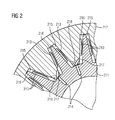
- FIG. 2 an alternative embodiment of a torsional vibration damper is shown, in which the primary part 211 has an external toothing, while the secondary part 212 has an internal toothing.
- inner and outer teeth in the circumferential direction to each other on a given game.
- chambers 215, 216 are formed with a viscous fluid, such as gear lubricating oil, in which disc springs 213 each between a tooth flank of the primary part 211 and a tooth flank of the secondary part 212 are clamped.
- the chambers 215, 216 are connected in pairs via channels 217, 218, each with a chamber pair associated compensation chambers 214.
- a channel 218 between a first chamber 215 of a chamber pair and the compensation chamber 214 is closed at a game-dependent falling below a predetermined minimum volume of the first chamber 215, while a channel 217 between a second chamber 216 of a chamber pair and the compensation chamber 214 in a game-dependent falling below a predetermined Minimum volume of the second chamber 216 is closed.
- the channel 218 between the first chamber 215 of a chamber pair and the compensation chamber 214 is completely open when a game-dependent falls below a predetermined minimum volume of the second chamber 216, while the channel 217 between a second chamber 216 of a chamber pair and the compensation chamber 214 in a game-dependent falling below a predetermined minimum volume of the first chamber 215 is fully open. This is a transition between closing a channel 217, 218 and fully opening a channel 217, 218 continuously.
- Another embodiment of a torsional vibration damper is in FIG.
- the torsional vibration damper is arranged on the rotor 21, which comprises a spaced apart by an air gap from the stator 22 outer rotor member 411 permanent magnet assembly and damper cage and a concentric with the outer rotor member 411 disposed inner rotor member 412 with permanent magnet assembly.
- the outer- ⁇ ere rotor element 411 is rotatably connected to the rotor shaft 28, while the inner rotor member 412 is rotatably connected to a drive-side gear shaft 29.
- the outer rotor member 411 and the inner rotor member 412 are interconnected by a fluid coupling 313.
- Radially disposed between the outer rotor member 411 and the inner rotor member 412 is an adjustable magnetic shield 314. This magnetic shield is deactivated at a slip below a predetermined threshold between the outer rotor member 411 and the inner rotor member 412 for establishing a magnetic coupling between the outer rotor member 411 and the inner rotor member 412.
Landscapes
- Engineering & Computer Science (AREA)
- Food Science & Technology (AREA)
- Connection Of Motors, Electrical Generators, Mechanical Devices, And The Like (AREA)
Abstract
Ein Getriebemotor für ein Mühlenantriebssystem umfaßt einen unterhalb oder seitlich eines Mahltellers anordenbares Getriebe (1) mit zumindest einer Planeten- (11,12) und/oder Stirnradstufe, das eine vertikale oder horizontale Wellenlage aufweist. In ein Gehäuse (3) des Getriebes (1) ist ein elektrischer Motor (2) integriert, dessen Rotor (21) und Stator (22) sich parallel zur Wellenlage des Getriebes (1) erstreckende Achsen aufweisen. Ein oberer Lagerdeckel (23) und ein unterer Lagerdeckel (24) sind an gegenüberliegenden Stirnseiten an Rotor (21) und/oder Stator (22) montiert und umfassen Lagersitze für Rotorwellenlager (26,27). Zwischen dem unteren Lagerdeckel (24) und einem Bodenteil des Gehäuses (3) ist eine Auffangwanne für Kühlmittel gebildet. Zwischen einem Hohlrad des Getriebes (1) und dem Gehäuse (3) oder radial zwischen einer Rotorwelle und einem Rotorträger, an dem Rotorwicklungen und/oder Rotormagnete befestigt sind, ist ein Drehschwingungsdämpfer angeordnet, der einen Primärteil (126,211) und einen drehelastisch mit dem Primärteil verbundenen Sekundärteil (311,212) umfaßt.A geared motor for a mill drive system comprises a gear (1) which can be arranged below or to the side of a grinding table and has at least one planetary (11, 12) and / or spur gear stage which has a vertical or horizontal shaft position. An electric motor (2) is integrated in a housing (3) of the transmission (1), the rotor (21) and stator (22) of which have axes extending parallel to the shaft position of the transmission (1). An upper bearing cover (23) and a lower bearing cover (24) are mounted on opposite end faces on the rotor (21) and / or stator (22) and comprise bearing seats for rotor shaft bearings (26, 27). A collecting trough for coolant is formed between the lower bearing cover (24) and a bottom part of the housing (3). A torsional vibration damper is arranged between a ring gear of the gearbox (1) and the housing (3) or radially between a rotor shaft and a rotor carrier, to which rotor windings and / or rotor magnets are attached, which has a primary part (126, 211) and a torsionally flexible with the primary part connected secondary part (311,212) includes.
Description
Bekannte Mühlenantriebssysteme umfassen eine oder mehrere Getriebestufen zur Antriebsleistungswandlung eines Elektromotors. Getriebestufen und Elektromotor bilden dabei einen eng an einen Verarbeitungsprozeß innerhalb z.B. einer Schüsselmühle, einer Mischtrommel, eines Brechers, einer Rohrmühle oder eines Drehrohrofens gekoppelten Antriebsstrang, der erheblichen Rückwirkungen des Verarbeitungsprozesses ausgesetzt ist. Üblicherweise werden Kegelradstufen zur Anbindung des Elektromotors an den Antriebsstrang verwendet.Known mill drive systems include one or more gear stages for driving power conversion of an electric motor. Gear stages and electric motor are closely linked to a processing process within e.g. a power plant coupled to a bowl mill, a mixing drum, a crusher, a tube mill or a rotary kiln, which is subject to considerable repercussions of the processing process. Usually bevel gear stages are used to connect the electric motor to the drive train.
In
Aus
In
Aus
In der älteren europäischen Patentanmeldung mit dem Anmeldeaktenzeichen
Die ältere europäische Patentanmeldung mit dem Anmeldeaktenzeichen
Der vorliegenden Erfindung liegt daher die Aufgabe zugrunde, einen Getriebemotor für ein Mühlenantriebssystem zu schaffen, der eine kostengünstig realisierbare Vermeidung von Getriebeschäden durch Kurzunterbrechungen im Antriebsstrang ermöglicht.The present invention is therefore an object of the invention to provide a geared motor for a mill drive system, which allows a cost-effective implementation of avoidable damage caused by short interruptions in the drive train.
Erfindungsgemäß wird diese Aufgabe durch einen Getriebemotor für ein Mühlenantriebssystem mit den in Anspruch 1 angegebenen Merkmalen gelöst. Vorteilhafte Weiterbildungen der vorliegenden Erfindung sind in den abhängigen Ansprüchen angegeben.According to the invention this object is achieved by a geared motor for a mill drive system having the features specified in claim 1. Advantageous developments of the present Invention are given in the dependent claims.
Der erfindungsgemäße Getriebemotor für ein Mühlenantriebssystem umfaßt einen unterhalb oder seitlich eines Mahltellers anordenbares Getriebe mit zumindest einer Planeten- und/oder Stirnradstufe, das eine vertikale oder horizontale Wellenlage aufweist. Außerdem ist ein in ein Gehäuse des Getriebes integrierter elektrischer Motor vorgesehen, dessen Rotor und Stator sich parallel zur Wellenlage des Getriebes erstreckende Achsen aufweisen. Ein oberer Lagerdeckel und ein unterer Lagerdeckel sind an gegenüberliegenden Stirnseiten an Rotor bzw. Stator montiert und umfassen Lagersitze für Rotorwellenlager. Der obere Lagerdeckel und der untere Lagerdeckel sind vorzugsweise durch einen Statorträger verbunden. Zwischen dem unteren Lagerdeckel und einem Bodenteil des Gehäuses ist darüber hinaus eine Auffangwanne für Kühlmittel gebildet. Vorzugsweise umfaßt der Getriebemotor einen an einer Innenseite des Gehäuses gebildeten, sich radial nach Innen erstreckenden Flansch, mit dem der untere und/oder obere Lagerdeckel verbunden sind/ist und über den der Motor abgestützt ist. Zwischen einem Hohlrad des Getriebes und dem Gehäuse oder radial zwischen einer Rotorwelle und einem Rotorträger, an dem Rotorwicklungen und/oder Rotormagnete befestigt sind, ist ein Drehschwingungsdämpfer angeordnet, der einen Primärteil und einen drehelastisch mit dem Primärteil verbundenen Sekundärteil umfaßt. Auf diese Weise ist kein Umrichter zur Motordrehzahlregelung und zur Entkopplung zwischen Netzversorgung und Motordrehmoment erforderlich, um Verzahnungsschäden z.B. bei Kurzunterbrechungen infolge eines Netzausfalls vermeiden zu können.The geared motor according to the invention for a mill drive system comprises a gearbox which can be arranged below or laterally of a grinding plate and has at least one planetary and / or spur gear stage which has a vertical or horizontal shaft position. In addition, an integrated in a housing of the transmission electric motor is provided, the rotor and stator have parallel to the shaft position of the transmission extending axes. An upper bearing cap and a lower bearing cap are mounted on opposite end faces of the rotor and stator, respectively, and include bearing seats for rotor shaft bearings. The upper bearing cap and the lower bearing cap are preferably connected by a stator carrier. Between the lower bearing cap and a bottom part of the housing beyond a collecting tray for coolant is formed. Preferably, the gear motor comprises a radially inwardly extending flange formed on an inner side of the housing to which the lower and / or upper bearing cap is / are connected and over which the motor is supported. Between a ring gear of the transmission and the housing or radially between a rotor shaft and a rotor carrier, are fixed to the rotor windings and / or rotor magnets, a torsional vibration damper is arranged, which comprises a primary part and a torsionally elastic connected to the primary part secondary part. In this way, no inverter for motor speed control and decoupling between mains supply and motor torque is required to avoid tooth damage, e.g. to avoid short interruptions due to a power failure.
Außerdem ermöglicht der erfindungsgemäße Getriebemotor eine einfache Montage einer Motoreinheit durch Einhängen in das Gehäuse am oberen und/oder unteren Lagerdeckel. Der Motor kann dabei im wesentlichen ausschließlich über den Flansch an der Innenseite des Gehäuses abgestützt sein. Durch eine komplett vertikale oder horizontale Anordnung von Mahlteller, Getriebe und Motor ist außerdem ein Verzicht auf verhältnismäßig teuere Kegelradgetriebe möglich.In addition, the geared motor according to the invention allows easy mounting of a motor unit by hanging in the Housing on the upper and / or lower bearing cover. The motor can be supported substantially exclusively via the flange on the inside of the housing. By a complete vertical or horizontal arrangement of grinding table, gearbox and engine is also a waiver of relatively expensive bevel gear possible.
Entsprechend einer bevorzugten Weiterbildung der vorliegenden Erfindung sind zwischen dem Primärteil und dem Sekundärteil des Drehschwingungsdämpfers Blattfederpakete angeordnet, die mit ihren Enden am Primärteil oder am Sekundärteil befestigt sind. Die Blattfederpakete sind beispielsweise innerhalb von mit einer viskosen Flüssigkeit gefüllten Kammern angeordnet. Die viskose Flüssigkeit kann Schmieröl des Getriebes sein. Hiermit ergibt sich eine besonders wirkungsvolle Ausgestaltung eines Drehschwingungsdämpfers mit hoher Dämpfung und reduzierter Drehsteifigkeit. Dies gilt auch für eine andere Ausführungsform der vorliegenden Erfindung, bei welcher der Drehschwingungsdämpfer durch eine Kupplung mit elastischen Bolzen gebildet ist, die jeweils in einer diese umschließenden Kammer angeordnet sind, die beispielsweise mit einer viskosen Flüssigkeit gefüllt ist.According to a preferred embodiment of the present invention, leaf spring assemblies are arranged between the primary part and the secondary part of the torsional vibration damper, which are fastened with their ends on the primary part or on the secondary part. The leaf spring packs are arranged, for example, within chambers filled with a viscous fluid. The viscous fluid may be lubricating oil of the transmission. This results in a particularly effective embodiment of a torsional vibration damper with high damping and reduced torsional stiffness. This also applies to another embodiment of the present invention, in which the torsional vibration damper is formed by a coupling with elastic bolts, which are each arranged in a chamber enclosing this, which is filled for example with a viscous liquid.
Die vorliegende Erfindung wird nachfolgend an einem Ausführungsbeispiel anhand der Zeichnung näher erläutert. Es zeigt
- Figur 1
- einen erfindungsgemäßen Getriebemotor für ein Mühlenantriebssystem in einer Schnittdarstellung,
Figur 2- ein Ausführungsbeispiel eines Drehschwingungsdämpfers für einen Getriebemotor gemäß
Figur 1 ,
- Figur 3
- ein weiteres Ausführungsbeispiel eines Drehschwingungsdämpfers für einen Getriebemotor gemäß
Figur 1 .
- FIG. 1
- a geared motor according to the invention for a mill drive system in a sectional view,
- FIG. 2
- an embodiment of a torsional vibration damper for a geared motor according to
FIG. 1 .
- FIG. 3
- a further embodiment of a torsional vibration damper for a geared motor according to
FIG. 1 ,
In
Der Motor 2 ist über einen an einer Innenseite des Gehäuses 3 gebildeten, sich radial nach Innen erstreckenden Flansch 34 abgestützt, mit dem der obere Lagerdeckel 23 verbunden ist. Der Motor 2 ist im vorliegenden Ausführungsbeispiel ausschließlich über den Flansch 34 an der Innenseite des Gehäuses 3 abgestützt.The
Beide Planetenstufen 11, 12 umfassen jeweils ein Hohlrad 111, 121, einen Planetenträger 114, 124 mit darin gelagerten Planetenrädern 112, 122 und ein Sonnenrad 113, 123. Die Hohlräder 111, 121 der Planetenstufen 11, 12 sind fest mit dem Gehäuse 3 verbunden. Der Planetenträger 124 einer abtriebsseitigen Planetenstufe 12 ist mittels eines Axiallagers 125 gelagert. Das Sonnenrad 113 der antriebsseitigen Planetenstufe 11 ist mit einer Rotorwelle des Motors 2 verbunden.Both
Rotorwelle und Sonnenradwelle der antriebsseitigen Planetenstufe 11 sind vorzugsweise über eine unterhalb oder oberhalb des Motors 2 angeordnete Kupplung verbunden. Darüber hinaus sind im vorliegenden Ausführungsbeispiel der Planetenträger 114 der antriebsseitigen Planetenstufe 11 und das Sonnenrad 123 der abtriebsseitigen Planetenstufe 12 miteinander verbunden.Rotor shaft and sun gear shaft of the drive-side
Der Motor 2 ist an einen Schmierstoffversorgungs- bzw. Kühlmittelkreislauf des Getriebes 1 angeschlossen. Auf diese Weise kann eine Kühlung des Motors 2 mittels durch das Getriebe 1 zirkulierenden Schmierstoffs erfolgen. Am Rotor 21 ist eine schmieröldichte Ummantelung zur Abdichtung gegenüber innerhalb des Gehäuses 3 zirkulierendem Schmierstoff vorgesehen. Vorzugsweise schließt sich in entsprechender Weise an einen Luftspalt zwischen Rotor 21 und Stator 22 in radialer Richtung eine schmieröldichte Ummantelung eines Ständerblechpakets an, das Wicklungen des Stators 22 umfaßt.The
Zur Kapselung des Stators 22 ist eine Hülse vorgesehen. Neben der Hülse weist der Stator 22 einen Klemmflansch, ein Klemmelement und eine elastische Abdichtung auf. Mit Hilfe des Klemmelementes wird ist die elastische Abdichtung auf den Klemmflansche und die Hülse gepreßt. Zur Kapselung des Stators 22 kann jedes geeignete Statorgehäuseteil verwendet werden, indem die elastische Abdichtung einen Druck durch eine Vorspannung auf dieses ausübt. Weitere Details zur Kapselung von Rotor 21 und Stator 22 sind der älteren deutschen Patentanmeldung
Im Rotor 21 sind mehrere sich axial erstreckende Öffnungen für einen Schmierstoffablauf vom Getriebe 1 in die Auffangwanne unterhalb des Motors 2 vorgesehen. Die Auffangwanne kann beispielsweise in einen inneren Bereich für Getriebeschmierstoff und in einen äußeren Bereich für Motorkühlmittel unterteilt sein.In the rotor 21 a plurality of axially extending openings for a lubricant outlet from the gearbox 1 are provided in the sump below the
Zwischen dem Hohlrad 121 der abtriebsseitigen Planetenstufe 12 und dem Gehäuse 3 und zusätzlich radial zwischen der Rotorwelle und einem Rotorträger, an dem Rotorwicklungen bzw. Rotormagnete befestigt sind, ist im vorliegenden Ausführungsbeispiel jeweils ein Drehschwingungsdämpfer vorgesehen, der einen Primärteil 126, 211 und einen drehelastisch mit dem Primärteil 126, 211 verbundenen Sekundärteil 311, 212 umfaßt. Grundsätzlich ist bereits ein Drehschwingungsdämpfer ausreichend, der beispielsweise auch zwischen dem Hohlrad 111 der abtriebsseitigen Planetenstufe 11 und dem Gehäuse 3 angeordnet sein könnte.Between the
Bei dem am Motor 2 angeordneten Drehschwingungsdämpfer sind im vorliegenden Ausführungsbeispiel zwischen dem Primärteil 211 und dem Sekundärteil 212 Blattfederpakete angeordnet, die mit ihren Enden am Primärteil 211 bzw. am Sekundärteil 212 befestigt sind. Die Blattfederpakete sind innerhalb von mit einer viskosen Flüssigkeit, vorzugsweise Getriebeschmieröl, gefüllten Kammern angeordnet.In the case of the torsional vibration damper arranged on the
Der am Hohlrad 121 der abtriebsseitigen Planetenstufe 12 angeordnete Drehschwingungsdämpfer ist durch eine Kupplung mit elastischen Bolzen 311 gebildet, die jeweils in einer diese umschließenden und mit einer viskosen Flüssigkeit gefüllten Kammer angeordnet sind. Die Bolzen 311 sind jeweils mittels einer Befestigungsschraube 312 mit dem Gehäuse 3 verbunden. Die Kammern sind durch sich parallel zur Wellenlage des Getriebes 1 erstreckenden Bohrungen in einem das Hohlrad 121 der abtriebsseitigen Planetenstufe 12 radial umgebenden Ring gebildet, der beispielsweise an das Hohlrad 121 angeformt ist.The arranged on the
Ein Drehschwingungsdämpfer mit Blattfederpakten kann alternativ zu einer Anordnung am Motor 2 auch an einem der beiden Hohlräder 111, 121 angeordnet sein. In analoger Weise gilt dies auch für den am Hohlrad 121 der abtriebsseitigen Planetenstufe 12 angeordnete Drehschwingungsdämpfer, der alternativ auch am Hohlrad 111 der antriebsseitigen Planetenstufe 11 oder am Motor 2 angeordnet sein kann.A torsional vibration damper with leaf spring assemblies may alternatively be arranged on one of the two ring gears 111, 121 as an arrangement on the
Grundsätzlich kann ein Drehschwingungsdämpfer auch durch eine Flüssigkeitskupplung oder durch ein schwimmend gelagertes Hohlrad, bei dem hydraulische oder pneumatische Dämpfer mit Federelementen bzw. winkelabhängiger Druckaufschaltung zwischen einem Hohlrad und einem Hohlradträger angeordnet sind, realisiert sein.In principle, a torsional vibration damper can also be realized by a fluid coupling or by a floating ring gear in which hydraulic or pneumatic dampers with spring elements or angle-dependent pressure connection between a ring gear and a ring gear carrier are arranged.
Im vorliegenden Ausführungsbeispiel ist der Motor 2 eine permanenterregte umrichterlose Synchronmaschine, deren Rotor-Magnetsystem in einen Edelstahlmantel eingeschweißt ist. Dies ermöglicht besonders geringe elektrische Verluste. Alternativ dazu kann das Rotor-Magnetsystem mit einem nichtleitenden bzw. nichtmagnetischen Werkstoff ummantelt sein.In the present embodiment, the
Bei dem in
In
Der Kanal 218 zwischen der ersten Kammer 215 eines Kammerpaars und der Ausgleichskammer 214 ist bei einem spielabhängigen Unterschreiten eines vorgegebenen Mindestvolumens der zweiten Kammer 216 vollständig geöffnet ist, während der Kanal 217 zwischen einer zweiten Kammer 216 eines Kammerpaars und der Ausgleichskammer 214 bei einem spielabhängigen Unterschreiten eines vorgegebenen Mindestvolumens der ersten Kammer 215 vollständig geöffnet ist. Dabei erfolgt ein Übergang zwischen einem Schließen eines Kanals 217, 218 und einem vollständigen Öffnen eines Kanals 217, 218 kontinuierlich. Eine weitere Ausführungsform eines Drehschwingungsdämpfers ist in
Die Anwendung der vorliegenden Erfindung ist nicht auf das beschriebene Ausführungsbeispiel beschränkt.The application of the present invention is not limited to the described embodiment.
Claims (17)
bei dem ein den oberen Lagerdeckel und den unteren Lagerdeckel verbindender Statorträger vorgesehen ist, und bei dem ein an einer Innenseite des Gehäuses gebildeter, sich radial nach Innen erstreckender Flansch vorgesehen ist, mit dem der untere und/oder obere Lagerdeckel verbunden sind/ist und über den der Motor abgestützt ist.Geared motor according to claim 1,
in which a stator carrier connecting the upper bearing cap and the lower bearing cap is provided, and in which a radially inwardly extending flange formed on an inner side of the housing is provided, to which the lower and / or upper bearing cap is / are connected and via the motor is supported.
bei dem zwischen dem Primärteil und dem Sekundärteil Blattfederpakete angeordnet sind, die mit ihren Enden am Primärteil oder am Sekundärteil befestigt sind.Geared motor according to one of claims 1 or 2,
in which leaf spring assemblies are arranged between the primary part and the secondary part, which are fastened with their ends to the primary part or to the secondary part.
bei dem die Blattfederpakete innerhalb von mit einer viskosen Flüssigkeit gefüllten Kammern angeordnet sind.Geared motor according to claim 3,
wherein the leaf spring packs are disposed within chambers filled with a viscous fluid.
bei dem die viskose Flüssigkeit Schmieröl des Getriebes ist.Geared motor according to claim 4,
wherein the viscous fluid is lubricating oil of the transmission.
bei dem der Primärteil eine Außenverzahnung aufweist, und bei dem der Sekundärteil eine Innenverzahnung aufweist, und bei dem Innen- und Außenverzahnung in Umfangsrichtung zueinander ein vorgegebenes Spiel aufweisen, und bei dem zwischen spielabhängig zueinander beabstandeten Zähnen des Primärteils und des Sekundärteils mit einer viskosen Flüssigkeit zumindest teilweise gefüllte Kammern gebildet sind, in denen Federelemente jeweils zwischen einer Zahnflanke des Primärteils und einer Zahnflanke des Sekundärteils eingespannnt sind, und bei dem die Kammern paarweise über Kanäle mit jeweils einem Kammerpaar zugeordneten Ausgleichkammern verbunden sind, und bei dem ein Kanal zwischen einer ersten Kammer eines Kammerpaars und der Ausgleichskammer bei einem spielabhängigen Unterschreiten eines vorgegebenen Mindestvolumens der ersten Kammer geschlossen ist, und bei dem ein Kanal zwischen einer zweiten Kammer eines Kammerpaars und der Ausgleichskammer bei einem spielabhängigen Unterschreiten eines vorgegebenen Mindestvolumens der zweiten Kammer geschlossen ist.Geared motor according to one of claims 1 or 2,
in which the primary part has an outer toothing, and in which the secondary part has an internal toothing, and in the inner and outer toothing in the circumferential direction to each other have a given clearance, and wherein at least between play-dependent spaced teeth of the primary part and the secondary part with a viscous liquid partially filled chambers are formed, in which spring elements are clamped in each case between a tooth flank of the primary part and a tooth flank of the secondary part, and in which the chambers are connected in pairs via channels, each with a chamber pair associated balance chambers, and wherein a channel between a first chamber of a Chamber pair and the compensation chamber is closed at a game-dependent falling below a predetermined minimum volume of the first chamber, and in which a channel between a second chamber of a chamber pair and the compensation chamber in a game-dependent U Next a predetermined minimum volume of the second chamber is closed.
bei dem der Kanal zwischen der ersten Kammer eines Kammerpaars und der Ausgleichskammer bei einem spielabhängigen Unterschreiten eines vorgegebenen Mindestvolumens der zweiten Kammer vollständig geöffnet ist, und bei dem der Kanal zwischen einer zweiten Kammer eines Kammerpaars und der Ausgleichskammer bei einem spielabhängigen Unterschreiten eines vorgegebenen Mindestvolumens der ersten Kammer vollständig geöffnet ist.Geared motor according to claim 6,
in which the channel between the first chamber of a pair of chambers and the compensation chamber is completely open in a game-dependent falling below a predetermined minimum volume of the second chamber, and wherein the channel between a second chamber of a chamber pair and the compensation chamber in a game-dependent falling below a predetermined minimum volume of the first Chamber is fully open.
bei dem ein Übergang zwischen einem Schließen eines Kanals und einem vollständigen Öffnen eines Kanals kontinuierlich erfolgt.Geared motor according to claim 7,
wherein a transition between closing a channel and fully opening a channel is continuous.
bei dem die viskose Flüssigkeit Schmieröl des Getriebes ist, und bei dem die Federelemente Tellerfedern sind.Geared motor according to one of claims 6 to 8,
wherein the viscous fluid is lubricating oil of the transmission, and wherein the spring elements are Belleville springs.
bei dem der Drehschwingungsdämpfer durch eine Kupplung mit elastischen Bolzen gebildet ist, die jeweils in einer diese umschließenden Kammer angeordnet sind.Geared motor according to one of claims 1 or 2,
wherein the torsional vibration damper is formed by a coupling with elastic bolts, which are each arranged in a chamber enclosing this.
bei dem die Kammern jeweils mit einer viskosen Flüssigkeit gefüllt sind.Geared motor according to claim 10,
in which the chambers are each filled with a viscous liquid.
bei dem der Drehschwingungsdämpfer am Rotor angeordnet ist, der ein durch einen Luftspalt vom Stator beabstandetes äußeres Rotorelement und ein konzentrisch zum äußeren Rotorelement angeordnetes inneres Rotorelement umfaßt, und bei dem das äußere Rotorelement mit der Rotorwelle drehfest verbunden ist, und bei dem das innere Rotorelement mit einer antriebsseitigen Getriebewelle drehfest verbunden ist, und bei dem das äußere Rotorelement und das innere Rotorelement durch eine Strömungskupplung miteinander verbunden sind, und bei dem radial zwischen dem äußeren Rotorelement und dem inneren Rotorelement eine einstellbare magnetische Abschirmung angeordnet ist, die bei einem unter einem vorgebbaren Schwellwert liegendem Schlupf zwischen dem äußeren Rotorelement und dem inneren Rotorelement zur Herstellung einer magnetischen Kopplung zwischen dem äußeren Rotorelement und dem inneren Rotorelement deaktiviert ist.Geared motor according to one of claims 1 or 2,
wherein the torsional vibration damper is disposed on the rotor, which comprises an outer rotor member spaced apart from the stator by an air gap and an inner rotor member concentric with the outer rotor member, and wherein the outer rotor member is rotatably connected to the rotor shaft and in which the inner rotor member is rotatably connected to a drive-side gear shaft, and wherein the outer rotor member and the inner rotor member are interconnected by a fluid coupling, and wherein an adjustable magnetic shield radially interposed between the outer rotor member and the inner rotor member is, which is deactivated at a lying below a predetermined threshold slip between the outer rotor member and the inner rotor member for producing a magnetic coupling between the outer rotor member and the inner rotor member.
bei dem der Motor im wesentlichen ausschließlich über den Flansch an der Innenseite des Gehäuses abgestützt ist.Geared motor according to one of claims 1 to 12,
wherein the motor is supported substantially exclusively by the flange on the inside of the housing.
bei dem zwischen einer Rotornabe und dem unteren Lagerdeckel zumindest ein Axiallager für die Rotorwelle angeordnet ist.Geared motor according to one of claims 1 to 13,
in which at least one thrust bearing for the rotor shaft is arranged between a rotor hub and the lower bearing cap.
bei dem der Motor an einen Schmierstoffversorgungs- und/oder Kühlmittelkreislauf des Getriebes angeschlossen ist.Geared motor according to one of claims 1 to 14,
in which the engine is connected to a lubricant supply and / or coolant circuit of the transmission.
bei dem der Motor eine permanenterregte Synchronmaschine ist, deren Rotor-Magnetsystem in einen Edelstahlmantel eingeschweißt ist.Geared motor according to one of claims 1 to 15,
in which the motor is a permanent-magnet synchronous machine whose rotor magnet system is welded into a stainless steel jacket.
bei dem der Motor eine permanenterregte umrichterlose Synchronmaschine ist.Geared motor according to one of claims 1 to 16,
in which the motor is a permanent magnet inverterless synchronous machine.
Priority Applications (4)
| Application Number | Priority Date | Filing Date | Title |
|---|---|---|---|
| EP20110155822 EP2492016B1 (en) | 2011-02-24 | 2011-02-24 | Gear motor for a mill drive system |
| EP13003158.6A EP2641658A1 (en) | 2011-02-24 | 2011-02-24 | Gear motor for a mill drive system |
| ES11155822T ES2429026T3 (en) | 2011-02-24 | 2011-02-24 | Gear motor for a mill drive system |
| CN201210041843.7A CN102649096B (en) | 2011-02-24 | 2012-02-22 | Gear motor for a mill drive system |
Applications Claiming Priority (1)
| Application Number | Priority Date | Filing Date | Title |
|---|---|---|---|
| EP20110155822 EP2492016B1 (en) | 2011-02-24 | 2011-02-24 | Gear motor for a mill drive system |
Related Child Applications (1)
| Application Number | Title | Priority Date | Filing Date |
|---|---|---|---|
| EP13003158.6 Division-Into | 2013-06-20 |
Publications (2)
| Publication Number | Publication Date |
|---|---|
| EP2492016A1 true EP2492016A1 (en) | 2012-08-29 |
| EP2492016B1 EP2492016B1 (en) | 2013-09-18 |
Family
ID=44168463
Family Applications (2)
| Application Number | Title | Priority Date | Filing Date |
|---|---|---|---|
| EP20110155822 Not-in-force EP2492016B1 (en) | 2011-02-24 | 2011-02-24 | Gear motor for a mill drive system |
| EP13003158.6A Withdrawn EP2641658A1 (en) | 2011-02-24 | 2011-02-24 | Gear motor for a mill drive system |
Family Applications After (1)
| Application Number | Title | Priority Date | Filing Date |
|---|---|---|---|
| EP13003158.6A Withdrawn EP2641658A1 (en) | 2011-02-24 | 2011-02-24 | Gear motor for a mill drive system |
Country Status (3)
| Country | Link |
|---|---|
| EP (2) | EP2492016B1 (en) |
| CN (1) | CN102649096B (en) |
| ES (1) | ES2429026T3 (en) |
Cited By (4)
| Publication number | Priority date | Publication date | Assignee | Title |
|---|---|---|---|---|
| WO2014111177A1 (en) * | 2013-01-16 | 2014-07-24 | Siemens Aktiengesellschaft | Drive regulating method and regulating device which operates according to the method |
| WO2015003716A1 (en) * | 2013-07-08 | 2015-01-15 | Flsmidth A/S | Heavy duty drive arrangement and mill |
| CN110259833A (en) * | 2019-05-28 | 2019-09-20 | 洛阳矿山机械工程设计研究院有限责任公司 | Free end pinion shaft bearing housing of a large double pinion driven mill |
| CN114160266A (en) * | 2021-11-09 | 2022-03-11 | 罗业基 | Silicon dioxide processing equipment before semiconductor raw material silicon production |
Families Citing this family (2)
| Publication number | Priority date | Publication date | Assignee | Title |
|---|---|---|---|---|
| FR3033864B1 (en) * | 2015-03-17 | 2017-04-21 | Cie Engrenages Et Reducteurs Messian Durand | REDUCER FOR AGITATOR SHREDDER, GRINDER AND USE THEREOF |
| CN108302162B (en) * | 2018-01-26 | 2020-10-27 | 常州工学院 | Planetary gear train based on high damping flexible support frame and design method of the support frame |
Citations (9)
| Publication number | Priority date | Publication date | Assignee | Title |
|---|---|---|---|---|
| CH405853A (en) * | 1963-06-10 | 1966-01-15 | Indive Gmbh | Planetary gear with internally toothed gear ring |
| FR1491699A (en) * | 1965-08-11 | 1967-08-11 | Pametrada | Improvement in epicyclic gears |
| DE2701205A1 (en) * | 1976-01-23 | 1977-07-28 | Geislinger Dr Ing Leonard | ROTARY VIBRATION DAMPER OR VIBRATION-DAMPING AND TORSO-ELASTIC COUPLING |
| DE3931116A1 (en) | 1989-09-18 | 1991-03-28 | Krupp Polysius Ag | Roller mill drive with axial and radial bearings - has axial bearing directly below gear rim acting as thrust plate, with radial bearing inside axial bearing |
| GB2250569A (en) * | 1990-12-07 | 1992-06-10 | Holset Engineering Co | Torsional vibration damping or coupling mechanism |
| JP2005052799A (en) | 2003-08-07 | 2005-03-03 | Seisa Gear Ltd | Gear device for vertical crushing machine |
| WO2008031694A1 (en) | 2006-09-14 | 2008-03-20 | Siemens Aktiengesellschaft | Mill for milling rough, stone-like bulk material with parallel to the axis drive |
| WO2009068484A1 (en) | 2007-11-28 | 2009-06-04 | Siemens Aktiengesellschaft | Spur gear |
| WO2010020287A1 (en) | 2008-08-22 | 2010-02-25 | Maag Gear Ag | Heavy-duty drive arrangement and mill driven by the same |
Family Cites Families (7)
| Publication number | Priority date | Publication date | Assignee | Title |
|---|---|---|---|---|
| US2192310A (en) * | 1938-06-30 | 1940-03-05 | Stanley D Hartshorn | Differential roll crusher |
| US5667149A (en) * | 1995-07-03 | 1997-09-16 | Foster Wheeler Energy Corporation | Solids pulverizer mill and process utilizing interactive air port nozzles |
| CN2518593Y (en) * | 2001-12-11 | 2002-10-30 | 林朝全 | Vertical roller grinder with connecting seat and fixed disc for ultra-fine powder output mechanism |
| DE10305915A1 (en) * | 2003-02-13 | 2004-08-26 | Alstom Power Boiler Gmbh | Rolling mill for e.g. dig-damp hard coal, includes driver with a ring engine that is concentric to a hollow shaft which in turn directly propels a meal plate, the shaft connected with a rotor |
| DE102009034158B4 (en) | 2009-07-20 | 2023-11-16 | Flender Gmbh | Encapsulation of an electrical machine |
| ES2378496T3 (en) | 2009-09-10 | 2012-04-13 | Siemens Aktiengesellschaft | Mill drive system |
| EP2457663B1 (en) | 2010-11-29 | 2014-01-01 | Siemens Aktiengesellschaft | Gear motor of a mill drive system |
-
2011
- 2011-02-24 EP EP20110155822 patent/EP2492016B1/en not_active Not-in-force
- 2011-02-24 ES ES11155822T patent/ES2429026T3/en active Active
- 2011-02-24 EP EP13003158.6A patent/EP2641658A1/en not_active Withdrawn
-
2012
- 2012-02-22 CN CN201210041843.7A patent/CN102649096B/en not_active Expired - Fee Related
Patent Citations (9)
| Publication number | Priority date | Publication date | Assignee | Title |
|---|---|---|---|---|
| CH405853A (en) * | 1963-06-10 | 1966-01-15 | Indive Gmbh | Planetary gear with internally toothed gear ring |
| FR1491699A (en) * | 1965-08-11 | 1967-08-11 | Pametrada | Improvement in epicyclic gears |
| DE2701205A1 (en) * | 1976-01-23 | 1977-07-28 | Geislinger Dr Ing Leonard | ROTARY VIBRATION DAMPER OR VIBRATION-DAMPING AND TORSO-ELASTIC COUPLING |
| DE3931116A1 (en) | 1989-09-18 | 1991-03-28 | Krupp Polysius Ag | Roller mill drive with axial and radial bearings - has axial bearing directly below gear rim acting as thrust plate, with radial bearing inside axial bearing |
| GB2250569A (en) * | 1990-12-07 | 1992-06-10 | Holset Engineering Co | Torsional vibration damping or coupling mechanism |
| JP2005052799A (en) | 2003-08-07 | 2005-03-03 | Seisa Gear Ltd | Gear device for vertical crushing machine |
| WO2008031694A1 (en) | 2006-09-14 | 2008-03-20 | Siemens Aktiengesellschaft | Mill for milling rough, stone-like bulk material with parallel to the axis drive |
| WO2009068484A1 (en) | 2007-11-28 | 2009-06-04 | Siemens Aktiengesellschaft | Spur gear |
| WO2010020287A1 (en) | 2008-08-22 | 2010-02-25 | Maag Gear Ag | Heavy-duty drive arrangement and mill driven by the same |
Cited By (9)
| Publication number | Priority date | Publication date | Assignee | Title |
|---|---|---|---|---|
| WO2014111177A1 (en) * | 2013-01-16 | 2014-07-24 | Siemens Aktiengesellschaft | Drive regulating method and regulating device which operates according to the method |
| WO2014111410A1 (en) * | 2013-01-16 | 2014-07-24 | Siemens Aktiengesellschaft | Drive control method and drive system operating according to said method |
| US9789488B2 (en) | 2013-01-16 | 2017-10-17 | Siemens Aktiengesellschaft | Drive control method and control device which operates according to the method |
| US10556238B2 (en) | 2013-01-16 | 2020-02-11 | Siemens Aktiengesellschaft | Drive control method and drive system operating according to said method |
| WO2015003716A1 (en) * | 2013-07-08 | 2015-01-15 | Flsmidth A/S | Heavy duty drive arrangement and mill |
| CN105377438A (en) * | 2013-07-08 | 2016-03-02 | Fl史密斯公司 | Heavy duty drive arrangement and mill |
| US10335797B2 (en) | 2013-07-08 | 2019-07-02 | Flsmidth A/S | Heavy duty drive arrangement and mill |
| CN110259833A (en) * | 2019-05-28 | 2019-09-20 | 洛阳矿山机械工程设计研究院有限责任公司 | Free end pinion shaft bearing housing of a large double pinion driven mill |
| CN114160266A (en) * | 2021-11-09 | 2022-03-11 | 罗业基 | Silicon dioxide processing equipment before semiconductor raw material silicon production |
Also Published As
| Publication number | Publication date |
|---|---|
| CN102649096B (en) | 2015-01-21 |
| EP2641658A1 (en) | 2013-09-25 |
| CN102649096A (en) | 2012-08-29 |
| ES2429026T3 (en) | 2013-11-12 |
| EP2492016B1 (en) | 2013-09-18 |
Similar Documents
| Publication | Publication Date | Title |
|---|---|---|
| EP2295147B1 (en) | Mill drive system | |
| EP2380666B1 (en) | Mill drive system | |
| EP2457663B1 (en) | Gear motor of a mill drive system | |
| EP2508754B1 (en) | Drive system for a wind turbine | |
| DE102007003107B4 (en) | Triple clutch for hybrid drive with dual-clutch transmission | |
| EP2492016B1 (en) | Gear motor for a mill drive system | |
| DE10154147C1 (en) | hybrid drive | |
| EP2871756B1 (en) | Crankshaft starter generator and housing for a crankshaft starter generator | |
| EP3206283A2 (en) | Electrical machine assembly, motor vehicle transmission gearboxes and method for producing an electrical machine assembly | |
| EP2481622A1 (en) | Assembly with combustion engine and planetary gear attached to same and motor vehicle | |
| EP2541096A1 (en) | Drive system for a wind turbine | |
| DE202010001318U1 (en) | Electric final drive assembly | |
| WO2004077644A2 (en) | Spare part set for a gearmotor series | |
| EP2964976B1 (en) | Geared motor arrangement | |
| DE102018131638B4 (en) | Motor-gearbox unit, in particular for a tunnel boring machine or for driving a gear ring | |
| DE2535418A1 (en) | DRIVE DEVICE FOR VEHICLES, IN PARTICULAR RAILWAY VEHICLES | |
| DE102022211895A1 (en) | Powertrain, electric drive axle and vehicle | |
| EP3142883A1 (en) | Integration of an electric-motor unit into a transmission housing | |
| WO2022073560A1 (en) | Electrical machine having a bearing of a connection shaft connected to a rotor | |
| EP2649711B1 (en) | Geared motor | |
| EP2061137A1 (en) | Method for mechanically connecting a disk motor | |
| DE102011079678A1 (en) | Gebriebemotor | |
| DE10221562A1 (en) | Device for connecting crankshaft to gearbox shaft, especially for internal combustion engine, has rotor arranged outside stator and with drive connection to drive side rotating ring | |
| DE19943048A1 (en) | Drive system e.g. for motor vehicle, has rotor arrangement with bearer arrangement for connection to or rotation with drive shaft, with one bearer region for rotor interaction region, and other connected to damper arrangement | |
| EP4244497B1 (en) | Transmission for a drive device for a vehicle, a gear for a transmission, and vehicle comprising a transmission |
Legal Events
| Date | Code | Title | Description |
|---|---|---|---|
| PUAI | Public reference made under article 153(3) epc to a published international application that has entered the european phase |
Free format text: ORIGINAL CODE: 0009012 |
|
| 17P | Request for examination filed |
Effective date: 20110819 |
|
| AK | Designated contracting states |
Kind code of ref document: A1 Designated state(s): AL AT BE BG CH CY CZ DE DK EE ES FI FR GB GR HR HU IE IS IT LI LT LU LV MC MK MT NL NO PL PT RO RS SE SI SK SM TR |
|
| AX | Request for extension of the european patent |
Extension state: BA ME |
|
| RAP1 | Party data changed (applicant data changed or rights of an application transferred) |
Owner name: SIEMENS AKTIENGESELLSCHAFT |
|
| GRAP | Despatch of communication of intention to grant a patent |
Free format text: ORIGINAL CODE: EPIDOSNIGR1 |
|
| INTG | Intention to grant announced |
Effective date: 20130408 |
|
| RIC1 | Information provided on ipc code assigned before grant |
Ipc: B02C 15/00 20060101AFI20130322BHEP |
|
| GRAS | Grant fee paid |
Free format text: ORIGINAL CODE: EPIDOSNIGR3 |
|
| GRAA | (expected) grant |
Free format text: ORIGINAL CODE: 0009210 |
|
| AK | Designated contracting states |
Kind code of ref document: B1 Designated state(s): AL AT BE BG CH CY CZ DE DK EE ES FI FR GB GR HR HU IE IS IT LI LT LU LV MC MK MT NL NO PL PT RO RS SE SI SK SM TR |
|
| REG | Reference to a national code |
Ref country code: GB Ref legal event code: FG4D Free format text: NOT ENGLISH |
|
| REG | Reference to a national code |
Ref country code: CH Ref legal event code: EP Ref country code: CH Ref legal event code: NV Representative=s name: SIEMENS SCHWEIZ AG, CH |
|
| REG | Reference to a national code |
Ref country code: IE Ref legal event code: FG4D Free format text: LANGUAGE OF EP DOCUMENT: GERMAN |
|
| REG | Reference to a national code |
Ref country code: AT Ref legal event code: REF Ref document number: 632437 Country of ref document: AT Kind code of ref document: T Effective date: 20131015 |
|
| REG | Reference to a national code |
Ref country code: ES Ref legal event code: FG2A Ref document number: 2429026 Country of ref document: ES Kind code of ref document: T3 Effective date: 20131112 |
|
| REG | Reference to a national code |
Ref country code: DE Ref legal event code: R096 Ref document number: 502011001350 Country of ref document: DE Effective date: 20131114 |
|
| PG25 | Lapsed in a contracting state [announced via postgrant information from national office to epo] |
Ref country code: LT Free format text: LAPSE BECAUSE OF FAILURE TO SUBMIT A TRANSLATION OF THE DESCRIPTION OR TO PAY THE FEE WITHIN THE PRESCRIBED TIME-LIMIT Effective date: 20130918 Ref country code: HR Free format text: LAPSE BECAUSE OF FAILURE TO SUBMIT A TRANSLATION OF THE DESCRIPTION OR TO PAY THE FEE WITHIN THE PRESCRIBED TIME-LIMIT Effective date: 20130918 Ref country code: CY Free format text: LAPSE BECAUSE OF FAILURE TO SUBMIT A TRANSLATION OF THE DESCRIPTION OR TO PAY THE FEE WITHIN THE PRESCRIBED TIME-LIMIT Effective date: 20130911 Ref country code: SE Free format text: LAPSE BECAUSE OF FAILURE TO SUBMIT A TRANSLATION OF THE DESCRIPTION OR TO PAY THE FEE WITHIN THE PRESCRIBED TIME-LIMIT Effective date: 20130918 Ref country code: NO Free format text: LAPSE BECAUSE OF FAILURE TO SUBMIT A TRANSLATION OF THE DESCRIPTION OR TO PAY THE FEE WITHIN THE PRESCRIBED TIME-LIMIT Effective date: 20131218 |
|
| REG | Reference to a national code |
Ref country code: NL Ref legal event code: VDEP Effective date: 20130918 |
|
| REG | Reference to a national code |
Ref country code: LT Ref legal event code: MG4D |
|
| PG25 | Lapsed in a contracting state [announced via postgrant information from national office to epo] |
Ref country code: GR Free format text: LAPSE BECAUSE OF FAILURE TO SUBMIT A TRANSLATION OF THE DESCRIPTION OR TO PAY THE FEE WITHIN THE PRESCRIBED TIME-LIMIT Effective date: 20131219 Ref country code: RS Free format text: LAPSE BECAUSE OF FAILURE TO SUBMIT A TRANSLATION OF THE DESCRIPTION OR TO PAY THE FEE WITHIN THE PRESCRIBED TIME-LIMIT Effective date: 20130918 Ref country code: LV Free format text: LAPSE BECAUSE OF FAILURE TO SUBMIT A TRANSLATION OF THE DESCRIPTION OR TO PAY THE FEE WITHIN THE PRESCRIBED TIME-LIMIT Effective date: 20130918 Ref country code: SI Free format text: LAPSE BECAUSE OF FAILURE TO SUBMIT A TRANSLATION OF THE DESCRIPTION OR TO PAY THE FEE WITHIN THE PRESCRIBED TIME-LIMIT Effective date: 20130918 |
|
| PG25 | Lapsed in a contracting state [announced via postgrant information from national office to epo] |
Ref country code: CY Free format text: LAPSE BECAUSE OF FAILURE TO SUBMIT A TRANSLATION OF THE DESCRIPTION OR TO PAY THE FEE WITHIN THE PRESCRIBED TIME-LIMIT Effective date: 20130918 |
|
| PG25 | Lapsed in a contracting state [announced via postgrant information from national office to epo] |
Ref country code: NL Free format text: LAPSE BECAUSE OF FAILURE TO SUBMIT A TRANSLATION OF THE DESCRIPTION OR TO PAY THE FEE WITHIN THE PRESCRIBED TIME-LIMIT Effective date: 20130918 Ref country code: CZ Free format text: LAPSE BECAUSE OF FAILURE TO SUBMIT A TRANSLATION OF THE DESCRIPTION OR TO PAY THE FEE WITHIN THE PRESCRIBED TIME-LIMIT Effective date: 20130918 Ref country code: SK Free format text: LAPSE BECAUSE OF FAILURE TO SUBMIT A TRANSLATION OF THE DESCRIPTION OR TO PAY THE FEE WITHIN THE PRESCRIBED TIME-LIMIT Effective date: 20130918 Ref country code: IS Free format text: LAPSE BECAUSE OF FAILURE TO SUBMIT A TRANSLATION OF THE DESCRIPTION OR TO PAY THE FEE WITHIN THE PRESCRIBED TIME-LIMIT Effective date: 20140118 Ref country code: EE Free format text: LAPSE BECAUSE OF FAILURE TO SUBMIT A TRANSLATION OF THE DESCRIPTION OR TO PAY THE FEE WITHIN THE PRESCRIBED TIME-LIMIT Effective date: 20130918 |
|
| PG25 | Lapsed in a contracting state [announced via postgrant information from national office to epo] |
Ref country code: PL Free format text: LAPSE BECAUSE OF FAILURE TO SUBMIT A TRANSLATION OF THE DESCRIPTION OR TO PAY THE FEE WITHIN THE PRESCRIBED TIME-LIMIT Effective date: 20130918 |
|
| REG | Reference to a national code |
Ref country code: DE Ref legal event code: R097 Ref document number: 502011001350 Country of ref document: DE |
|
| PG25 | Lapsed in a contracting state [announced via postgrant information from national office to epo] |
Ref country code: PT Free format text: LAPSE BECAUSE OF FAILURE TO SUBMIT A TRANSLATION OF THE DESCRIPTION OR TO PAY THE FEE WITHIN THE PRESCRIBED TIME-LIMIT Effective date: 20140120 |
|
| PLBE | No opposition filed within time limit |
Free format text: ORIGINAL CODE: 0009261 |
|
| STAA | Information on the status of an ep patent application or granted ep patent |
Free format text: STATUS: NO OPPOSITION FILED WITHIN TIME LIMIT |
|
| 26N | No opposition filed |
Effective date: 20140619 |
|
| PG25 | Lapsed in a contracting state [announced via postgrant information from national office to epo] |
Ref country code: DK Free format text: LAPSE BECAUSE OF FAILURE TO SUBMIT A TRANSLATION OF THE DESCRIPTION OR TO PAY THE FEE WITHIN THE PRESCRIBED TIME-LIMIT Effective date: 20130918 Ref country code: MC Free format text: LAPSE BECAUSE OF FAILURE TO SUBMIT A TRANSLATION OF THE DESCRIPTION OR TO PAY THE FEE WITHIN THE PRESCRIBED TIME-LIMIT Effective date: 20130918 Ref country code: LU Free format text: LAPSE BECAUSE OF FAILURE TO SUBMIT A TRANSLATION OF THE DESCRIPTION OR TO PAY THE FEE WITHIN THE PRESCRIBED TIME-LIMIT Effective date: 20140224 |
|
| REG | Reference to a national code |
Ref country code: DE Ref legal event code: R097 Ref document number: 502011001350 Country of ref document: DE Effective date: 20140619 |
|
| REG | Reference to a national code |
Ref country code: IE Ref legal event code: MM4A |
|
| PG25 | Lapsed in a contracting state [announced via postgrant information from national office to epo] |
Ref country code: IE Free format text: LAPSE BECAUSE OF NON-PAYMENT OF DUE FEES Effective date: 20140224 |
|
| REG | Reference to a national code |
Ref country code: FR Ref legal event code: PLFP Year of fee payment: 6 |
|
| PG25 | Lapsed in a contracting state [announced via postgrant information from national office to epo] |
Ref country code: MT Free format text: LAPSE BECAUSE OF FAILURE TO SUBMIT A TRANSLATION OF THE DESCRIPTION OR TO PAY THE FEE WITHIN THE PRESCRIBED TIME-LIMIT Effective date: 20130918 |
|
| PG25 | Lapsed in a contracting state [announced via postgrant information from national office to epo] |
Ref country code: SM Free format text: LAPSE BECAUSE OF FAILURE TO SUBMIT A TRANSLATION OF THE DESCRIPTION OR TO PAY THE FEE WITHIN THE PRESCRIBED TIME-LIMIT Effective date: 20130918 |
|
| PGFP | Annual fee paid to national office [announced via postgrant information from national office to epo] |
Ref country code: ES Payment date: 20160328 Year of fee payment: 6 Ref country code: IT Payment date: 20160225 Year of fee payment: 6 |
|
| PG25 | Lapsed in a contracting state [announced via postgrant information from national office to epo] |
Ref country code: RO Free format text: LAPSE BECAUSE OF FAILURE TO SUBMIT A TRANSLATION OF THE DESCRIPTION OR TO PAY THE FEE WITHIN THE PRESCRIBED TIME-LIMIT Effective date: 20130918 |
|
| PGFP | Annual fee paid to national office [announced via postgrant information from national office to epo] |
Ref country code: GB Payment date: 20160208 Year of fee payment: 6 Ref country code: BE Payment date: 20160217 Year of fee payment: 6 Ref country code: FR Payment date: 20160212 Year of fee payment: 6 Ref country code: FI Payment date: 20160211 Year of fee payment: 6 |
|
| PG25 | Lapsed in a contracting state [announced via postgrant information from national office to epo] |
Ref country code: BG Free format text: LAPSE BECAUSE OF FAILURE TO SUBMIT A TRANSLATION OF THE DESCRIPTION OR TO PAY THE FEE WITHIN THE PRESCRIBED TIME-LIMIT Effective date: 20130918 |
|
| PG25 | Lapsed in a contracting state [announced via postgrant information from national office to epo] |
Ref country code: HU Free format text: LAPSE BECAUSE OF FAILURE TO SUBMIT A TRANSLATION OF THE DESCRIPTION OR TO PAY THE FEE WITHIN THE PRESCRIBED TIME-LIMIT; INVALID AB INITIO Effective date: 20110224 Ref country code: TR Free format text: LAPSE BECAUSE OF FAILURE TO SUBMIT A TRANSLATION OF THE DESCRIPTION OR TO PAY THE FEE WITHIN THE PRESCRIBED TIME-LIMIT Effective date: 20130918 |
|
| PGFP | Annual fee paid to national office [announced via postgrant information from national office to epo] |
Ref country code: DE Payment date: 20160420 Year of fee payment: 6 Ref country code: CH Payment date: 20160502 Year of fee payment: 6 |
|
| REG | Reference to a national code |
Ref country code: AT Ref legal event code: MM01 Ref document number: 632437 Country of ref document: AT Kind code of ref document: T Effective date: 20160224 |
|
| PG25 | Lapsed in a contracting state [announced via postgrant information from national office to epo] |
Ref country code: AT Free format text: LAPSE BECAUSE OF NON-PAYMENT OF DUE FEES Effective date: 20160224 Ref country code: BE Free format text: LAPSE BECAUSE OF NON-PAYMENT OF DUE FEES Effective date: 20170228 |
|
| REG | Reference to a national code |
Ref country code: DE Ref legal event code: R119 Ref document number: 502011001350 Country of ref document: DE |
|
| REG | Reference to a national code |
Ref country code: CH Ref legal event code: PL |
|
| GBPC | Gb: european patent ceased through non-payment of renewal fee |
Effective date: 20170224 |
|
| PG25 | Lapsed in a contracting state [announced via postgrant information from national office to epo] |
Ref country code: LI Free format text: LAPSE BECAUSE OF NON-PAYMENT OF DUE FEES Effective date: 20170228 Ref country code: FI Free format text: LAPSE BECAUSE OF NON-PAYMENT OF DUE FEES Effective date: 20170224 Ref country code: CH Free format text: LAPSE BECAUSE OF NON-PAYMENT OF DUE FEES Effective date: 20170228 |
|
| REG | Reference to a national code |
Ref country code: FR Ref legal event code: ST Effective date: 20171031 |
|
| PG25 | Lapsed in a contracting state [announced via postgrant information from national office to epo] |
Ref country code: DE Free format text: LAPSE BECAUSE OF NON-PAYMENT OF DUE FEES Effective date: 20170901 Ref country code: FR Free format text: LAPSE BECAUSE OF NON-PAYMENT OF DUE FEES Effective date: 20170228 |
|
| REG | Reference to a national code |
Ref country code: BE Ref legal event code: MM Effective date: 20170228 |
|
| PG25 | Lapsed in a contracting state [announced via postgrant information from national office to epo] |
Ref country code: GB Free format text: LAPSE BECAUSE OF NON-PAYMENT OF DUE FEES Effective date: 20170224 Ref country code: IT Free format text: LAPSE BECAUSE OF NON-PAYMENT OF DUE FEES Effective date: 20170224 |
|
| REG | Reference to a national code |
Ref country code: ES Ref legal event code: FD2A Effective date: 20180627 |
|
| PG25 | Lapsed in a contracting state [announced via postgrant information from national office to epo] |
Ref country code: MK Free format text: LAPSE BECAUSE OF FAILURE TO SUBMIT A TRANSLATION OF THE DESCRIPTION OR TO PAY THE FEE WITHIN THE PRESCRIBED TIME-LIMIT Effective date: 20130918 |
|
| PG25 | Lapsed in a contracting state [announced via postgrant information from national office to epo] |
Ref country code: ES Free format text: LAPSE BECAUSE OF NON-PAYMENT OF DUE FEES Effective date: 20170225 |
|
| PG25 | Lapsed in a contracting state [announced via postgrant information from national office to epo] |
Ref country code: AL Free format text: LAPSE BECAUSE OF FAILURE TO SUBMIT A TRANSLATION OF THE DESCRIPTION OR TO PAY THE FEE WITHIN THE PRESCRIBED TIME-LIMIT Effective date: 20130918 |