EP2492016A1 - Moteur d'engrenage pour un système d'entraînement de moulin - Google Patents
Moteur d'engrenage pour un système d'entraînement de moulin Download PDFInfo
- Publication number
- EP2492016A1 EP2492016A1 EP11155822A EP11155822A EP2492016A1 EP 2492016 A1 EP2492016 A1 EP 2492016A1 EP 11155822 A EP11155822 A EP 11155822A EP 11155822 A EP11155822 A EP 11155822A EP 2492016 A1 EP2492016 A1 EP 2492016A1
- Authority
- EP
- European Patent Office
- Prior art keywords
- rotor
- chamber
- geared motor
- motor according
- housing
- Prior art date
- Legal status (The legal status is an assumption and is not a legal conclusion. Google has not performed a legal analysis and makes no representation as to the accuracy of the status listed.)
- Granted
Links
- 230000005540 biological transmission Effects 0.000 claims abstract description 24
- 239000002826 coolant Substances 0.000 claims abstract description 7
- 238000004804 winding Methods 0.000 claims abstract description 5
- 230000001419 dependent effect Effects 0.000 claims description 12
- 239000012530 fluid Substances 0.000 claims description 11
- 230000008878 coupling Effects 0.000 claims description 9
- 238000010168 coupling process Methods 0.000 claims description 9
- 238000005859 coupling reaction Methods 0.000 claims description 9
- 239000000314 lubricant Substances 0.000 claims description 9
- 239000010687 lubricating oil Substances 0.000 claims description 6
- 230000000712 assembly Effects 0.000 claims description 4
- 238000000429 assembly Methods 0.000 claims description 4
- 239000007788 liquid Substances 0.000 claims description 3
- 230000001360 synchronised effect Effects 0.000 claims description 3
- 229910001220 stainless steel Inorganic materials 0.000 claims description 2
- 239000010935 stainless steel Substances 0.000 claims description 2
- 230000007704 transition Effects 0.000 claims description 2
- 238000001816 cooling Methods 0.000 description 5
- 238000000034 method Methods 0.000 description 3
- 238000005538 encapsulation Methods 0.000 description 2
- 230000001050 lubricating effect Effects 0.000 description 2
- 238000006243 chemical reaction Methods 0.000 description 1
- 238000010276 construction Methods 0.000 description 1
- 238000013016 damping Methods 0.000 description 1
- 238000011161 development Methods 0.000 description 1
- 230000018109 developmental process Effects 0.000 description 1
- 238000007667 floating Methods 0.000 description 1
- 239000000696 magnetic material Substances 0.000 description 1
- 238000007789 sealing Methods 0.000 description 1
- 230000035939 shock Effects 0.000 description 1
Images


Classifications
-
- B—PERFORMING OPERATIONS; TRANSPORTING
- B02—CRUSHING, PULVERISING, OR DISINTEGRATING; PREPARATORY TREATMENT OF GRAIN FOR MILLING
- B02C—CRUSHING, PULVERISING, OR DISINTEGRATING IN GENERAL; MILLING GRAIN
- B02C15/00—Disintegrating by milling members in the form of rollers or balls co-operating with rings or discs
- B02C15/006—Ring or disc drive gear arrangement
Definitions
- Known mill drive systems include one or more gear stages for driving power conversion of an electric motor.
- Gear stages and electric motor are closely linked to a processing process within e.g. a power plant coupled to a bowl mill, a mixing drum, a crusher, a tube mill or a rotary kiln, which is subject to considerable repercussions of the processing process.
- bevel gear stages are used to connect the electric motor to the drive train.
- WO 2008/031694 Al discloses a mill drive system having a gear unit locatable below a grinding table.
- the transmission comprises at least one planetary stage and has a vertical shaft position.
- an electric motor is integrated, which is connected to a lubricant supply circuit of the transmission, whose rotor and stator have vertically extending axes and whose cooling is carried out by means of circulating through the gear lubricant.
- WO 2009/068484 Al is a spur gear with one or more gear stages for driving a gear wheel enclosed by a work machine described which includes a transmission gear housing receiving the gear and arranged on an output shaft of an output stage, adjustable movable pinion meshing with the ring gear.
- the gear housing consists of a first inherently rigid housing part and a second rigid housing part.
- the first housing part encloses the output stage with the output shaft and the adjustable pinion gear and has the transmission on outstanding side walls, which rest on the foundation.
- the second housing part is fastened to the first housing part without contact with the foundation on one end face.
- WO 2010/20287 is a mill drive system with an integrated motor-gear unit is known which has a common cooling circuit.
- the motor-gear unit is supported on a bottom plate of a housing comprising the motor-gear unit.
- a mill drive system is described with a can be arranged below a grinding table gear with at least one planetary and / or spur and an integrated in a housing of the transmission electric motor.
- the mill drive system comprises a converter with an associated control device for non-interlocking speed control of the motor.
- the older European patent application with the filing sign 10015077.0 discloses a geared motor for a mill drive system comprising a gear train, which can be arranged below a grinding table or laterally of a grinding drum, with at least one planetary gear stage having either a vertical shaft position or a horizontal shaft position.
- an electric motor is integrated in a housing of the transmission, which is connected to a lubricant supply circuit of the transmission.
- a converter is provided with an associated control device for the non-interlocking speed control of the motor.
- a ring gear of the at least one planetary gear is radially surrounded by both a rotor and a stator of the motor.
- the present invention is therefore an object of the invention to provide a geared motor for a mill drive system, which allows a cost-effective implementation of avoidable damage caused by short interruptions in the drive train.
- the geared motor according to the invention for a mill drive system comprises a gearbox which can be arranged below or laterally of a grinding plate and has at least one planetary and / or spur gear stage which has a vertical or horizontal shaft position.
- an integrated in a housing of the transmission electric motor is provided, the rotor and stator have parallel to the shaft position of the transmission extending axes.
- An upper bearing cap and a lower bearing cap are mounted on opposite end faces of the rotor and stator, respectively, and include bearing seats for rotor shaft bearings.
- the upper bearing cap and the lower bearing cap are preferably connected by a stator carrier. Between the lower bearing cap and a bottom part of the housing beyond a collecting tray for coolant is formed.
- the gear motor comprises a radially inwardly extending flange formed on an inner side of the housing to which the lower and / or upper bearing cap is / are connected and over which the motor is supported.
- a torsional vibration damper is arranged, which comprises a primary part and a torsionally elastic connected to the primary part secondary part.
- the geared motor according to the invention allows easy mounting of a motor unit by hanging in the Housing on the upper and / or lower bearing cover.
- the motor can be supported substantially exclusively via the flange on the inside of the housing.
- leaf spring assemblies are arranged between the primary part and the secondary part of the torsional vibration damper, which are fastened with their ends on the primary part or on the secondary part.
- the leaf spring packs are arranged, for example, within chambers filled with a viscous fluid.
- the viscous fluid may be lubricating oil of the transmission.
- the torsional vibration damper is formed by a coupling with elastic bolts, which are each arranged in a chamber enclosing this, which is filled for example with a viscous liquid.
- FIG. 1 a geared motor for a mill drive system is shown, which comprises a arranged below a grinding table gear 1 with two planetary stages 11, 12 having a vertical shaft position.
- an electric motor 2 is integrated, the rotor 21 and stator 22 having vertically extending axes.
- an upper bearing cap 23 and a lower bearing cap 24 are mounted on rotor 21 and stator 22, the bearing seats for rotor shaft bearings 26, 27 include.
- the upper bearing cap 23 and the lower bearing cap 24 are connected via a stator 25, which on an outer circumference in FIG. 2 has shown cooling fins 28. On these cooling fins 28 mounted on the housing 3 pointed nozzles 35 are aligned. Between the lower bearing cap 24 and a bottom part of the housing 3, a collecting tray for coolant is formed.
- the motor 2 is supported by a radially inwardly extending flange 34 formed on an inner side of the housing 3 to which the upper bearing cap 23 is connected.
- the motor 2 is supported in the present embodiment exclusively via the flange 34 on the inside of the housing 3.
- Both planetary stages 11, 12 each include a ring gear 111, 121, a planetary carrier 114, 124 with planetary gears 112, 122 and a sun gear 113, 123 mounted therein.
- the ring gears 111, 121 of the planetary stages 11, 12 are fixedly connected to the housing 3.
- the planet carrier 124 of a driven-side planetary stage 12 is supported by means of an axial bearing 125.
- the sun gear 113 of the drive-side planetary stage 11 is connected to a rotor shaft of the motor 2.
- Rotor shaft and sun gear shaft of the drive-side planetary stage 11 are preferably connected via a coupling arranged below or above the motor 2.
- the planet carrier 114 of the drive-side planetary stage 11 and the sun gear 123 of the output-side planetary stage 12 are connected to each other.
- the engine 2 is connected to a lubricant supply or coolant circuit of the transmission 1. In this way, a cooling of the engine 2 by means of circulating through the gear 1 lubricant can take place.
- a lubricating oil-tight sheath for sealing relative to inside the housing 3 circulating lubricant is provided.
- a lubricating oil-tight sheathing of a stator core which includes windings of the stator 22.
- a sleeve is provided for encapsulation of the stator 22.
- the stator 22 has a clamping flange, a clamping element and an elastic seal. With the help of the clamping element, the elastic seal is pressed onto the clamping flanges and the sleeve.
- any suitable stator housing part may be used by the elastic seal exerting a pressure by a bias on this. Further details on the encapsulation of rotor 21 and stator 22 are the older German patent application DE 10 2009 034 158.7 , the disclosure of which is hereby incorporated by reference.
- a plurality of axially extending openings for a lubricant outlet from the gearbox 1 are provided in the sump below the motor 2.
- the sump may be divided into an inner region for transmission lubricant and an outer region for engine coolant.
- a torsional vibration damper provided a primary part 126, 211 and a torsionally flexible the secondary part 311, 212 connected to the primary part 126, 211.
- a torsional vibration damper is sufficient, which could for example also be arranged between the ring gear 111 of the driven-side planetary stage 11 and the housing 3.
- leaf spring packets are arranged between the primary part 211 and the secondary part 212, which spring struts are fastened by their ends to the primary part 211 or to the secondary part 212.
- the leaf spring assemblies are disposed within chambers filled with a viscous fluid, preferably gear lubricating oil.
- the arranged on the ring gear 121 of the output-side planetary stage 12 torsional vibration damper is formed by a coupling with elastic bolts 311, which are each arranged in a surrounding this and filled with a viscous fluid chamber.
- the bolts 311 are each connected to the housing 3 by means of a fastening screw 312.
- the chambers are parallel to the shaft position of the transmission 1 extending bores in a the ring gear 121 of the output-side planetary stage 12 radially surrounding ring formed, for example, to the ring gear 121 is formed.
- a torsional vibration damper with leaf spring assemblies may alternatively be arranged on one of the two ring gears 111, 121 as an arrangement on the engine 2. In an analogous manner, this also applies to the arranged on the ring gear 121 of the output-side planetary stage 12 torsional vibration damper, which may alternatively be arranged on the ring gear 111 of the drive-side planetary stage 11 or the motor 2.
- a torsional vibration damper can also be realized by a fluid coupling or by a floating ring gear in which hydraulic or pneumatic dampers with spring elements or angle-dependent pressure connection between a ring gear and a ring gear carrier are arranged.
- the motor 2 is a permanent-magnet inverterless synchronous machine whose rotor magnet system is welded in a stainless steel sheath. This allows particularly low electrical losses.
- the rotor magnet system can be encased with a non-conductive or non-magnetic material.
- gear motor is disposed between a hub of the rotor 21 and the lower bearing cap 24, a thrust bearing 27 for the rotor shaft.
- the housing 3 is designed in two parts in the present embodiment and comprises a driven-side housing part 31 and a drive-side housing parts 32. In this case, in a region between the output-side planetary stage 12 and the drive-side planetary stage 11 a Gesimousetrennfuge 33 is provided.
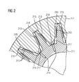
- FIG. 2 an alternative embodiment of a torsional vibration damper is shown, in which the primary part 211 has an external toothing, while the secondary part 212 has an internal toothing.
- inner and outer teeth in the circumferential direction to each other on a given game.
- chambers 215, 216 are formed with a viscous fluid, such as gear lubricating oil, in which disc springs 213 each between a tooth flank of the primary part 211 and a tooth flank of the secondary part 212 are clamped.
- the chambers 215, 216 are connected in pairs via channels 217, 218, each with a chamber pair associated compensation chambers 214.
- a channel 218 between a first chamber 215 of a chamber pair and the compensation chamber 214 is closed at a game-dependent falling below a predetermined minimum volume of the first chamber 215, while a channel 217 between a second chamber 216 of a chamber pair and the compensation chamber 214 in a game-dependent falling below a predetermined Minimum volume of the second chamber 216 is closed.
- the channel 218 between the first chamber 215 of a chamber pair and the compensation chamber 214 is completely open when a game-dependent falls below a predetermined minimum volume of the second chamber 216, while the channel 217 between a second chamber 216 of a chamber pair and the compensation chamber 214 in a game-dependent falling below a predetermined minimum volume of the first chamber 215 is fully open. This is a transition between closing a channel 217, 218 and fully opening a channel 217, 218 continuously.
- Another embodiment of a torsional vibration damper is in FIG.
- the torsional vibration damper is arranged on the rotor 21, which comprises a spaced apart by an air gap from the stator 22 outer rotor member 411 permanent magnet assembly and damper cage and a concentric with the outer rotor member 411 disposed inner rotor member 412 with permanent magnet assembly.
- the outer- ⁇ ere rotor element 411 is rotatably connected to the rotor shaft 28, while the inner rotor member 412 is rotatably connected to a drive-side gear shaft 29.
- the outer rotor member 411 and the inner rotor member 412 are interconnected by a fluid coupling 313.
- Radially disposed between the outer rotor member 411 and the inner rotor member 412 is an adjustable magnetic shield 314. This magnetic shield is deactivated at a slip below a predetermined threshold between the outer rotor member 411 and the inner rotor member 412 for establishing a magnetic coupling between the outer rotor member 411 and the inner rotor member 412.
Landscapes
- Engineering & Computer Science (AREA)
- Food Science & Technology (AREA)
- Connection Of Motors, Electrical Generators, Mechanical Devices, And The Like (AREA)
Priority Applications (4)
| Application Number | Priority Date | Filing Date | Title |
|---|---|---|---|
| EP20110155822 EP2492016B1 (fr) | 2011-02-24 | 2011-02-24 | Moteur d'engrenage pour un système d'entraînement de moulin |
| EP13003158.6A EP2641658A1 (fr) | 2011-02-24 | 2011-02-24 | Moteur d'engrenage pour un système d'entraînement de moulin |
| ES11155822T ES2429026T3 (es) | 2011-02-24 | 2011-02-24 | Motor de engranaje para un sistema de accionamiento de molino |
| CN201210041843.7A CN102649096B (zh) | 2011-02-24 | 2012-02-22 | 用于磨机驱动系统的变速马达 |
Applications Claiming Priority (1)
| Application Number | Priority Date | Filing Date | Title |
|---|---|---|---|
| EP20110155822 EP2492016B1 (fr) | 2011-02-24 | 2011-02-24 | Moteur d'engrenage pour un système d'entraînement de moulin |
Related Child Applications (1)
| Application Number | Title | Priority Date | Filing Date |
|---|---|---|---|
| EP13003158.6 Division-Into | 2013-06-20 |
Publications (2)
| Publication Number | Publication Date |
|---|---|
| EP2492016A1 true EP2492016A1 (fr) | 2012-08-29 |
| EP2492016B1 EP2492016B1 (fr) | 2013-09-18 |
Family
ID=44168463
Family Applications (2)
| Application Number | Title | Priority Date | Filing Date |
|---|---|---|---|
| EP20110155822 Not-in-force EP2492016B1 (fr) | 2011-02-24 | 2011-02-24 | Moteur d'engrenage pour un système d'entraînement de moulin |
| EP13003158.6A Withdrawn EP2641658A1 (fr) | 2011-02-24 | 2011-02-24 | Moteur d'engrenage pour un système d'entraînement de moulin |
Family Applications After (1)
| Application Number | Title | Priority Date | Filing Date |
|---|---|---|---|
| EP13003158.6A Withdrawn EP2641658A1 (fr) | 2011-02-24 | 2011-02-24 | Moteur d'engrenage pour un système d'entraînement de moulin |
Country Status (3)
| Country | Link |
|---|---|
| EP (2) | EP2492016B1 (fr) |
| CN (1) | CN102649096B (fr) |
| ES (1) | ES2429026T3 (fr) |
Cited By (4)
| Publication number | Priority date | Publication date | Assignee | Title |
|---|---|---|---|---|
| WO2014111177A1 (fr) * | 2013-01-16 | 2014-07-24 | Siemens Aktiengesellschaft | Procédé de réglage d'entraînement ainsi que dispositif de réglage fonctionnant selon le procédé |
| WO2015003716A1 (fr) * | 2013-07-08 | 2015-01-15 | Flsmidth A/S | Agencement d'entraînement à haut rendement et broyeur |
| CN110259833A (zh) * | 2019-05-28 | 2019-09-20 | 洛阳矿山机械工程设计研究院有限责任公司 | 一种大型双小齿轮驱动磨机的自由端小齿轮轴轴承座 |
| CN114160266A (zh) * | 2021-11-09 | 2022-03-11 | 罗业基 | 一种半导体原材料硅生产前二氧化硅加工设备 |
Families Citing this family (2)
| Publication number | Priority date | Publication date | Assignee | Title |
|---|---|---|---|---|
| FR3033864B1 (fr) * | 2015-03-17 | 2017-04-21 | Cie Engrenages Et Reducteurs Messian Durand | Reducteur pour broyeur a agitation, broyeur et utilisation correspondants |
| CN108302162B (zh) * | 2018-01-26 | 2020-10-27 | 常州工学院 | 基于高阻尼柔性支承架的行星轮系及该支承架的设计方法 |
Citations (9)
| Publication number | Priority date | Publication date | Assignee | Title |
|---|---|---|---|---|
| CH405853A (de) * | 1963-06-10 | 1966-01-15 | Indive Gmbh | Umlaufrädergetriebe mit innenverzahntem Getriebering |
| FR1491699A (fr) * | 1965-08-11 | 1967-08-11 | Pametrada | Perfectionnement aux engrenages épicycloïdaux |
| DE2701205A1 (de) * | 1976-01-23 | 1977-07-28 | Geislinger Dr Ing Leonard | Drehschwingungsdaempfer bzw. schwingungsdaempfende und drehelastische kupplung |
| DE3931116A1 (de) | 1989-09-18 | 1991-03-28 | Krupp Polysius Ag | Antriebseinrichtung fuer eine rollenmuehle |
| GB2250569A (en) * | 1990-12-07 | 1992-06-10 | Holset Engineering Co | Torsional vibration damping or coupling mechanism |
| JP2005052799A (ja) | 2003-08-07 | 2005-03-03 | Seisa Gear Ltd | 立形粉砕機用歯車装置 |
| WO2008031694A1 (fr) | 2006-09-14 | 2008-03-20 | Siemens Aktiengesellschaft | Broyeur pour le moulage de gros matériaux en vrac, du genre pierres, avec moteur parallèle à l'axe |
| WO2009068484A1 (fr) | 2007-11-28 | 2009-06-04 | Siemens Aktiengesellschaft | Engrenage cylindrique |
| WO2010020287A1 (fr) | 2008-08-22 | 2010-02-25 | Maag Gear Ag | Dispositif d'entraînement pour charges importantes et broyeur entraîné par ce dispositif |
Family Cites Families (7)
| Publication number | Priority date | Publication date | Assignee | Title |
|---|---|---|---|---|
| US2192310A (en) * | 1938-06-30 | 1940-03-05 | Stanley D Hartshorn | Differential roll crusher |
| US5667149A (en) * | 1995-07-03 | 1997-09-16 | Foster Wheeler Energy Corporation | Solids pulverizer mill and process utilizing interactive air port nozzles |
| CN2518593Y (zh) * | 2001-12-11 | 2002-10-30 | 林朝全 | 超微细粉输出机构具有连接座及固定盘的立式滚轮研磨机 |
| DE10305915A1 (de) * | 2003-02-13 | 2004-08-26 | Alstom Power Boiler Gmbh | Wälzmühle |
| DE102009034158B4 (de) | 2009-07-20 | 2023-11-16 | Flender Gmbh | Kapselung einer elektrischen Maschine |
| ES2378496T3 (es) | 2009-09-10 | 2012-04-13 | Siemens Aktiengesellschaft | Sistema de accionamiento de molino |
| EP2457663B1 (fr) | 2010-11-29 | 2014-01-01 | Siemens Aktiengesellschaft | Moteur d'engrenage d'un système d'entraînement de moulin |
-
2011
- 2011-02-24 EP EP20110155822 patent/EP2492016B1/fr not_active Not-in-force
- 2011-02-24 ES ES11155822T patent/ES2429026T3/es active Active
- 2011-02-24 EP EP13003158.6A patent/EP2641658A1/fr not_active Withdrawn
-
2012
- 2012-02-22 CN CN201210041843.7A patent/CN102649096B/zh not_active Expired - Fee Related
Patent Citations (9)
| Publication number | Priority date | Publication date | Assignee | Title |
|---|---|---|---|---|
| CH405853A (de) * | 1963-06-10 | 1966-01-15 | Indive Gmbh | Umlaufrädergetriebe mit innenverzahntem Getriebering |
| FR1491699A (fr) * | 1965-08-11 | 1967-08-11 | Pametrada | Perfectionnement aux engrenages épicycloïdaux |
| DE2701205A1 (de) * | 1976-01-23 | 1977-07-28 | Geislinger Dr Ing Leonard | Drehschwingungsdaempfer bzw. schwingungsdaempfende und drehelastische kupplung |
| DE3931116A1 (de) | 1989-09-18 | 1991-03-28 | Krupp Polysius Ag | Antriebseinrichtung fuer eine rollenmuehle |
| GB2250569A (en) * | 1990-12-07 | 1992-06-10 | Holset Engineering Co | Torsional vibration damping or coupling mechanism |
| JP2005052799A (ja) | 2003-08-07 | 2005-03-03 | Seisa Gear Ltd | 立形粉砕機用歯車装置 |
| WO2008031694A1 (fr) | 2006-09-14 | 2008-03-20 | Siemens Aktiengesellschaft | Broyeur pour le moulage de gros matériaux en vrac, du genre pierres, avec moteur parallèle à l'axe |
| WO2009068484A1 (fr) | 2007-11-28 | 2009-06-04 | Siemens Aktiengesellschaft | Engrenage cylindrique |
| WO2010020287A1 (fr) | 2008-08-22 | 2010-02-25 | Maag Gear Ag | Dispositif d'entraînement pour charges importantes et broyeur entraîné par ce dispositif |
Cited By (9)
| Publication number | Priority date | Publication date | Assignee | Title |
|---|---|---|---|---|
| WO2014111177A1 (fr) * | 2013-01-16 | 2014-07-24 | Siemens Aktiengesellschaft | Procédé de réglage d'entraînement ainsi que dispositif de réglage fonctionnant selon le procédé |
| WO2014111410A1 (fr) * | 2013-01-16 | 2014-07-24 | Siemens Aktiengesellschaft | Procédé de réglage d'entraînement et système d'entraînement fonctionnant selon ce procédé |
| US9789488B2 (en) | 2013-01-16 | 2017-10-17 | Siemens Aktiengesellschaft | Drive control method and control device which operates according to the method |
| US10556238B2 (en) | 2013-01-16 | 2020-02-11 | Siemens Aktiengesellschaft | Drive control method and drive system operating according to said method |
| WO2015003716A1 (fr) * | 2013-07-08 | 2015-01-15 | Flsmidth A/S | Agencement d'entraînement à haut rendement et broyeur |
| CN105377438A (zh) * | 2013-07-08 | 2016-03-02 | Fl史密斯公司 | 重型驱动装置和粉碎机 |
| US10335797B2 (en) | 2013-07-08 | 2019-07-02 | Flsmidth A/S | Heavy duty drive arrangement and mill |
| CN110259833A (zh) * | 2019-05-28 | 2019-09-20 | 洛阳矿山机械工程设计研究院有限责任公司 | 一种大型双小齿轮驱动磨机的自由端小齿轮轴轴承座 |
| CN114160266A (zh) * | 2021-11-09 | 2022-03-11 | 罗业基 | 一种半导体原材料硅生产前二氧化硅加工设备 |
Also Published As
| Publication number | Publication date |
|---|---|
| CN102649096B (zh) | 2015-01-21 |
| EP2641658A1 (fr) | 2013-09-25 |
| CN102649096A (zh) | 2012-08-29 |
| ES2429026T3 (es) | 2013-11-12 |
| EP2492016B1 (fr) | 2013-09-18 |
Similar Documents
| Publication | Publication Date | Title |
|---|---|---|
| EP2295147B1 (fr) | Système d'entraînement de moulin | |
| EP2380666B1 (fr) | Système d'entraînement de moulin | |
| EP2457663B1 (fr) | Moteur d'engrenage d'un système d'entraînement de moulin | |
| EP2508754B1 (fr) | Système de transmission pour une éolienne | |
| DE102007003107B4 (de) | Dreifachkupplung für Hybridantrieb mit Doppelkupplungsgetriebe | |
| EP2492016B1 (fr) | Moteur d'engrenage pour un système d'entraînement de moulin | |
| DE10154147C1 (de) | Hybridantrieb | |
| EP2871756B1 (fr) | Générateur de démarreur de vilebrequin et boîtier pour un tel générateur | |
| EP3206283A2 (fr) | Système de machine électrique, boîte de vitesses de véhicule automobile et procédé de production d'un système de machine électrique | |
| EP2481622A1 (fr) | Agencement doté d'un moteur à combustion interne et d'un engrenage épicycloïdal y étant accouplé et véhicule automobile | |
| EP2541096A1 (fr) | Système de propulsion pour une éolienne | |
| DE202010001318U1 (de) | Elektrische Achsantriebsbaugruppe | |
| WO2004077644A2 (fr) | Jeu de pieces detachees pour une serie de motoreducteurs | |
| EP2964976B1 (fr) | Ensemble motoréducteur | |
| DE102018131638B4 (de) | Motor-Getriebe-Einheit, insbesondere für eine Tunnelbohrmaschine oder zum Antrieb eines Zahnkranzes | |
| DE2535418A1 (de) | Antriebsvorrichtung fuer fahrzeuge, insbesondere eisenbahnfahrzeuge | |
| DE102022211895A1 (de) | Antriebsstrang, elektrische Antriebsachse und Fahrzeug | |
| EP3142883A1 (fr) | Intégration d'un ensemble moteur électrique dans un carter de transmission | |
| WO2022073560A1 (fr) | Machine électrique comprenant un palier d'un arbre de liaison relié à un rotor | |
| EP2649711B1 (fr) | Motoréducteur | |
| EP2061137A1 (fr) | Dispositif de raccordement de machine d'un moteur à disque | |
| DE102011079678A1 (de) | Gebriebemotor | |
| DE10221562A1 (de) | Vorrichtung zur Verbindung einer Kurbelwelle mit einer Getriebewelle | |
| DE19943048A1 (de) | Antriebssystem | |
| EP4244497B1 (fr) | Transmission pour un dispositif d'entraînement pour un véhicule, roue dentée pour une transmission, et véhicule comprenant une transmission |
Legal Events
| Date | Code | Title | Description |
|---|---|---|---|
| PUAI | Public reference made under article 153(3) epc to a published international application that has entered the european phase |
Free format text: ORIGINAL CODE: 0009012 |
|
| 17P | Request for examination filed |
Effective date: 20110819 |
|
| AK | Designated contracting states |
Kind code of ref document: A1 Designated state(s): AL AT BE BG CH CY CZ DE DK EE ES FI FR GB GR HR HU IE IS IT LI LT LU LV MC MK MT NL NO PL PT RO RS SE SI SK SM TR |
|
| AX | Request for extension of the european patent |
Extension state: BA ME |
|
| RAP1 | Party data changed (applicant data changed or rights of an application transferred) |
Owner name: SIEMENS AKTIENGESELLSCHAFT |
|
| GRAP | Despatch of communication of intention to grant a patent |
Free format text: ORIGINAL CODE: EPIDOSNIGR1 |
|
| INTG | Intention to grant announced |
Effective date: 20130408 |
|
| RIC1 | Information provided on ipc code assigned before grant |
Ipc: B02C 15/00 20060101AFI20130322BHEP |
|
| GRAS | Grant fee paid |
Free format text: ORIGINAL CODE: EPIDOSNIGR3 |
|
| GRAA | (expected) grant |
Free format text: ORIGINAL CODE: 0009210 |
|
| AK | Designated contracting states |
Kind code of ref document: B1 Designated state(s): AL AT BE BG CH CY CZ DE DK EE ES FI FR GB GR HR HU IE IS IT LI LT LU LV MC MK MT NL NO PL PT RO RS SE SI SK SM TR |
|
| REG | Reference to a national code |
Ref country code: GB Ref legal event code: FG4D Free format text: NOT ENGLISH |
|
| REG | Reference to a national code |
Ref country code: CH Ref legal event code: EP Ref country code: CH Ref legal event code: NV Representative=s name: SIEMENS SCHWEIZ AG, CH |
|
| REG | Reference to a national code |
Ref country code: IE Ref legal event code: FG4D Free format text: LANGUAGE OF EP DOCUMENT: GERMAN |
|
| REG | Reference to a national code |
Ref country code: AT Ref legal event code: REF Ref document number: 632437 Country of ref document: AT Kind code of ref document: T Effective date: 20131015 |
|
| REG | Reference to a national code |
Ref country code: ES Ref legal event code: FG2A Ref document number: 2429026 Country of ref document: ES Kind code of ref document: T3 Effective date: 20131112 |
|
| REG | Reference to a national code |
Ref country code: DE Ref legal event code: R096 Ref document number: 502011001350 Country of ref document: DE Effective date: 20131114 |
|
| PG25 | Lapsed in a contracting state [announced via postgrant information from national office to epo] |
Ref country code: LT Free format text: LAPSE BECAUSE OF FAILURE TO SUBMIT A TRANSLATION OF THE DESCRIPTION OR TO PAY THE FEE WITHIN THE PRESCRIBED TIME-LIMIT Effective date: 20130918 Ref country code: HR Free format text: LAPSE BECAUSE OF FAILURE TO SUBMIT A TRANSLATION OF THE DESCRIPTION OR TO PAY THE FEE WITHIN THE PRESCRIBED TIME-LIMIT Effective date: 20130918 Ref country code: CY Free format text: LAPSE BECAUSE OF FAILURE TO SUBMIT A TRANSLATION OF THE DESCRIPTION OR TO PAY THE FEE WITHIN THE PRESCRIBED TIME-LIMIT Effective date: 20130911 Ref country code: SE Free format text: LAPSE BECAUSE OF FAILURE TO SUBMIT A TRANSLATION OF THE DESCRIPTION OR TO PAY THE FEE WITHIN THE PRESCRIBED TIME-LIMIT Effective date: 20130918 Ref country code: NO Free format text: LAPSE BECAUSE OF FAILURE TO SUBMIT A TRANSLATION OF THE DESCRIPTION OR TO PAY THE FEE WITHIN THE PRESCRIBED TIME-LIMIT Effective date: 20131218 |
|
| REG | Reference to a national code |
Ref country code: NL Ref legal event code: VDEP Effective date: 20130918 |
|
| REG | Reference to a national code |
Ref country code: LT Ref legal event code: MG4D |
|
| PG25 | Lapsed in a contracting state [announced via postgrant information from national office to epo] |
Ref country code: GR Free format text: LAPSE BECAUSE OF FAILURE TO SUBMIT A TRANSLATION OF THE DESCRIPTION OR TO PAY THE FEE WITHIN THE PRESCRIBED TIME-LIMIT Effective date: 20131219 Ref country code: RS Free format text: LAPSE BECAUSE OF FAILURE TO SUBMIT A TRANSLATION OF THE DESCRIPTION OR TO PAY THE FEE WITHIN THE PRESCRIBED TIME-LIMIT Effective date: 20130918 Ref country code: LV Free format text: LAPSE BECAUSE OF FAILURE TO SUBMIT A TRANSLATION OF THE DESCRIPTION OR TO PAY THE FEE WITHIN THE PRESCRIBED TIME-LIMIT Effective date: 20130918 Ref country code: SI Free format text: LAPSE BECAUSE OF FAILURE TO SUBMIT A TRANSLATION OF THE DESCRIPTION OR TO PAY THE FEE WITHIN THE PRESCRIBED TIME-LIMIT Effective date: 20130918 |
|
| PG25 | Lapsed in a contracting state [announced via postgrant information from national office to epo] |
Ref country code: CY Free format text: LAPSE BECAUSE OF FAILURE TO SUBMIT A TRANSLATION OF THE DESCRIPTION OR TO PAY THE FEE WITHIN THE PRESCRIBED TIME-LIMIT Effective date: 20130918 |
|
| PG25 | Lapsed in a contracting state [announced via postgrant information from national office to epo] |
Ref country code: NL Free format text: LAPSE BECAUSE OF FAILURE TO SUBMIT A TRANSLATION OF THE DESCRIPTION OR TO PAY THE FEE WITHIN THE PRESCRIBED TIME-LIMIT Effective date: 20130918 Ref country code: CZ Free format text: LAPSE BECAUSE OF FAILURE TO SUBMIT A TRANSLATION OF THE DESCRIPTION OR TO PAY THE FEE WITHIN THE PRESCRIBED TIME-LIMIT Effective date: 20130918 Ref country code: SK Free format text: LAPSE BECAUSE OF FAILURE TO SUBMIT A TRANSLATION OF THE DESCRIPTION OR TO PAY THE FEE WITHIN THE PRESCRIBED TIME-LIMIT Effective date: 20130918 Ref country code: IS Free format text: LAPSE BECAUSE OF FAILURE TO SUBMIT A TRANSLATION OF THE DESCRIPTION OR TO PAY THE FEE WITHIN THE PRESCRIBED TIME-LIMIT Effective date: 20140118 Ref country code: EE Free format text: LAPSE BECAUSE OF FAILURE TO SUBMIT A TRANSLATION OF THE DESCRIPTION OR TO PAY THE FEE WITHIN THE PRESCRIBED TIME-LIMIT Effective date: 20130918 |
|
| PG25 | Lapsed in a contracting state [announced via postgrant information from national office to epo] |
Ref country code: PL Free format text: LAPSE BECAUSE OF FAILURE TO SUBMIT A TRANSLATION OF THE DESCRIPTION OR TO PAY THE FEE WITHIN THE PRESCRIBED TIME-LIMIT Effective date: 20130918 |
|
| REG | Reference to a national code |
Ref country code: DE Ref legal event code: R097 Ref document number: 502011001350 Country of ref document: DE |
|
| PG25 | Lapsed in a contracting state [announced via postgrant information from national office to epo] |
Ref country code: PT Free format text: LAPSE BECAUSE OF FAILURE TO SUBMIT A TRANSLATION OF THE DESCRIPTION OR TO PAY THE FEE WITHIN THE PRESCRIBED TIME-LIMIT Effective date: 20140120 |
|
| PLBE | No opposition filed within time limit |
Free format text: ORIGINAL CODE: 0009261 |
|
| STAA | Information on the status of an ep patent application or granted ep patent |
Free format text: STATUS: NO OPPOSITION FILED WITHIN TIME LIMIT |
|
| 26N | No opposition filed |
Effective date: 20140619 |
|
| PG25 | Lapsed in a contracting state [announced via postgrant information from national office to epo] |
Ref country code: DK Free format text: LAPSE BECAUSE OF FAILURE TO SUBMIT A TRANSLATION OF THE DESCRIPTION OR TO PAY THE FEE WITHIN THE PRESCRIBED TIME-LIMIT Effective date: 20130918 Ref country code: MC Free format text: LAPSE BECAUSE OF FAILURE TO SUBMIT A TRANSLATION OF THE DESCRIPTION OR TO PAY THE FEE WITHIN THE PRESCRIBED TIME-LIMIT Effective date: 20130918 Ref country code: LU Free format text: LAPSE BECAUSE OF FAILURE TO SUBMIT A TRANSLATION OF THE DESCRIPTION OR TO PAY THE FEE WITHIN THE PRESCRIBED TIME-LIMIT Effective date: 20140224 |
|
| REG | Reference to a national code |
Ref country code: DE Ref legal event code: R097 Ref document number: 502011001350 Country of ref document: DE Effective date: 20140619 |
|
| REG | Reference to a national code |
Ref country code: IE Ref legal event code: MM4A |
|
| PG25 | Lapsed in a contracting state [announced via postgrant information from national office to epo] |
Ref country code: IE Free format text: LAPSE BECAUSE OF NON-PAYMENT OF DUE FEES Effective date: 20140224 |
|
| REG | Reference to a national code |
Ref country code: FR Ref legal event code: PLFP Year of fee payment: 6 |
|
| PG25 | Lapsed in a contracting state [announced via postgrant information from national office to epo] |
Ref country code: MT Free format text: LAPSE BECAUSE OF FAILURE TO SUBMIT A TRANSLATION OF THE DESCRIPTION OR TO PAY THE FEE WITHIN THE PRESCRIBED TIME-LIMIT Effective date: 20130918 |
|
| PG25 | Lapsed in a contracting state [announced via postgrant information from national office to epo] |
Ref country code: SM Free format text: LAPSE BECAUSE OF FAILURE TO SUBMIT A TRANSLATION OF THE DESCRIPTION OR TO PAY THE FEE WITHIN THE PRESCRIBED TIME-LIMIT Effective date: 20130918 |
|
| PGFP | Annual fee paid to national office [announced via postgrant information from national office to epo] |
Ref country code: ES Payment date: 20160328 Year of fee payment: 6 Ref country code: IT Payment date: 20160225 Year of fee payment: 6 |
|
| PG25 | Lapsed in a contracting state [announced via postgrant information from national office to epo] |
Ref country code: RO Free format text: LAPSE BECAUSE OF FAILURE TO SUBMIT A TRANSLATION OF THE DESCRIPTION OR TO PAY THE FEE WITHIN THE PRESCRIBED TIME-LIMIT Effective date: 20130918 |
|
| PGFP | Annual fee paid to national office [announced via postgrant information from national office to epo] |
Ref country code: GB Payment date: 20160208 Year of fee payment: 6 Ref country code: BE Payment date: 20160217 Year of fee payment: 6 Ref country code: FR Payment date: 20160212 Year of fee payment: 6 Ref country code: FI Payment date: 20160211 Year of fee payment: 6 |
|
| PG25 | Lapsed in a contracting state [announced via postgrant information from national office to epo] |
Ref country code: BG Free format text: LAPSE BECAUSE OF FAILURE TO SUBMIT A TRANSLATION OF THE DESCRIPTION OR TO PAY THE FEE WITHIN THE PRESCRIBED TIME-LIMIT Effective date: 20130918 |
|
| PG25 | Lapsed in a contracting state [announced via postgrant information from national office to epo] |
Ref country code: HU Free format text: LAPSE BECAUSE OF FAILURE TO SUBMIT A TRANSLATION OF THE DESCRIPTION OR TO PAY THE FEE WITHIN THE PRESCRIBED TIME-LIMIT; INVALID AB INITIO Effective date: 20110224 Ref country code: TR Free format text: LAPSE BECAUSE OF FAILURE TO SUBMIT A TRANSLATION OF THE DESCRIPTION OR TO PAY THE FEE WITHIN THE PRESCRIBED TIME-LIMIT Effective date: 20130918 |
|
| PGFP | Annual fee paid to national office [announced via postgrant information from national office to epo] |
Ref country code: DE Payment date: 20160420 Year of fee payment: 6 Ref country code: CH Payment date: 20160502 Year of fee payment: 6 |
|
| REG | Reference to a national code |
Ref country code: AT Ref legal event code: MM01 Ref document number: 632437 Country of ref document: AT Kind code of ref document: T Effective date: 20160224 |
|
| PG25 | Lapsed in a contracting state [announced via postgrant information from national office to epo] |
Ref country code: AT Free format text: LAPSE BECAUSE OF NON-PAYMENT OF DUE FEES Effective date: 20160224 Ref country code: BE Free format text: LAPSE BECAUSE OF NON-PAYMENT OF DUE FEES Effective date: 20170228 |
|
| REG | Reference to a national code |
Ref country code: DE Ref legal event code: R119 Ref document number: 502011001350 Country of ref document: DE |
|
| REG | Reference to a national code |
Ref country code: CH Ref legal event code: PL |
|
| GBPC | Gb: european patent ceased through non-payment of renewal fee |
Effective date: 20170224 |
|
| PG25 | Lapsed in a contracting state [announced via postgrant information from national office to epo] |
Ref country code: LI Free format text: LAPSE BECAUSE OF NON-PAYMENT OF DUE FEES Effective date: 20170228 Ref country code: FI Free format text: LAPSE BECAUSE OF NON-PAYMENT OF DUE FEES Effective date: 20170224 Ref country code: CH Free format text: LAPSE BECAUSE OF NON-PAYMENT OF DUE FEES Effective date: 20170228 |
|
| REG | Reference to a national code |
Ref country code: FR Ref legal event code: ST Effective date: 20171031 |
|
| PG25 | Lapsed in a contracting state [announced via postgrant information from national office to epo] |
Ref country code: DE Free format text: LAPSE BECAUSE OF NON-PAYMENT OF DUE FEES Effective date: 20170901 Ref country code: FR Free format text: LAPSE BECAUSE OF NON-PAYMENT OF DUE FEES Effective date: 20170228 |
|
| REG | Reference to a national code |
Ref country code: BE Ref legal event code: MM Effective date: 20170228 |
|
| PG25 | Lapsed in a contracting state [announced via postgrant information from national office to epo] |
Ref country code: GB Free format text: LAPSE BECAUSE OF NON-PAYMENT OF DUE FEES Effective date: 20170224 Ref country code: IT Free format text: LAPSE BECAUSE OF NON-PAYMENT OF DUE FEES Effective date: 20170224 |
|
| REG | Reference to a national code |
Ref country code: ES Ref legal event code: FD2A Effective date: 20180627 |
|
| PG25 | Lapsed in a contracting state [announced via postgrant information from national office to epo] |
Ref country code: MK Free format text: LAPSE BECAUSE OF FAILURE TO SUBMIT A TRANSLATION OF THE DESCRIPTION OR TO PAY THE FEE WITHIN THE PRESCRIBED TIME-LIMIT Effective date: 20130918 |
|
| PG25 | Lapsed in a contracting state [announced via postgrant information from national office to epo] |
Ref country code: ES Free format text: LAPSE BECAUSE OF NON-PAYMENT OF DUE FEES Effective date: 20170225 |
|
| PG25 | Lapsed in a contracting state [announced via postgrant information from national office to epo] |
Ref country code: AL Free format text: LAPSE BECAUSE OF FAILURE TO SUBMIT A TRANSLATION OF THE DESCRIPTION OR TO PAY THE FEE WITHIN THE PRESCRIBED TIME-LIMIT Effective date: 20130918 |