EP2492068A1 - Schneidvorrichtung - Google Patents
Schneidvorrichtung Download PDFInfo
- Publication number
- EP2492068A1 EP2492068A1 EP20120155083 EP12155083A EP2492068A1 EP 2492068 A1 EP2492068 A1 EP 2492068A1 EP 20120155083 EP20120155083 EP 20120155083 EP 12155083 A EP12155083 A EP 12155083A EP 2492068 A1 EP2492068 A1 EP 2492068A1
- Authority
- EP
- European Patent Office
- Prior art keywords
- unit
- moving
- cutting
- substrate
- rectangular substrate
- Prior art date
- Legal status (The legal status is an assumption and is not a legal conclusion. Google has not performed a legal analysis and makes no representation as to the accuracy of the status listed.)
- Withdrawn
Links
- 238000005520 cutting process Methods 0.000 title claims abstract description 116
- 239000000758 substrate Substances 0.000 claims abstract description 130
- 238000012546 transfer Methods 0.000 claims abstract description 16
- 230000008859 change Effects 0.000 claims abstract description 6
- 230000007246 mechanism Effects 0.000 claims description 46
- 238000000034 method Methods 0.000 description 4
- 230000008569 process Effects 0.000 description 3
- 238000012545 processing Methods 0.000 description 3
- 238000010586 diagram Methods 0.000 description 2
- 101000911772 Homo sapiens Hsc70-interacting protein Proteins 0.000 description 1
- 101001139126 Homo sapiens Krueppel-like factor 6 Proteins 0.000 description 1
- 101000661807 Homo sapiens Suppressor of tumorigenicity 14 protein Proteins 0.000 description 1
- 238000013459 approach Methods 0.000 description 1
- 238000001514 detection method Methods 0.000 description 1
- 230000000694 effects Effects 0.000 description 1
- 239000011521 glass Substances 0.000 description 1
- 238000009434 installation Methods 0.000 description 1
- 238000012986 modification Methods 0.000 description 1
- 230000004048 modification Effects 0.000 description 1
- 239000004065 semiconductor Substances 0.000 description 1
- 238000004904 shortening Methods 0.000 description 1
- 238000012360 testing method Methods 0.000 description 1
Images





Classifications
-
- B—PERFORMING OPERATIONS; TRANSPORTING
- B26—HAND CUTTING TOOLS; CUTTING; SEVERING
- B26D—CUTTING; DETAILS COMMON TO MACHINES FOR PERFORATING, PUNCHING, CUTTING-OUT, STAMPING-OUT OR SEVERING
- B26D3/00—Cutting work characterised by the nature of the cut made; Apparatus therefor
- B26D3/10—Making cuts of other than simple rectilinear form
-
- B—PERFORMING OPERATIONS; TRANSPORTING
- B26—HAND CUTTING TOOLS; CUTTING; SEVERING
- B26D—CUTTING; DETAILS COMMON TO MACHINES FOR PERFORATING, PUNCHING, CUTTING-OUT, STAMPING-OUT OR SEVERING
- B26D1/00—Cutting through work characterised by the nature or movement of the cutting member or particular materials not otherwise provided for; Apparatus or machines therefor; Cutting members therefor
- B26D1/01—Cutting through work characterised by the nature or movement of the cutting member or particular materials not otherwise provided for; Apparatus or machines therefor; Cutting members therefor involving a cutting member which does not travel with the work
- B26D1/12—Cutting through work characterised by the nature or movement of the cutting member or particular materials not otherwise provided for; Apparatus or machines therefor; Cutting members therefor involving a cutting member which does not travel with the work having a cutting member moving about an axis
- B26D1/14—Cutting through work characterised by the nature or movement of the cutting member or particular materials not otherwise provided for; Apparatus or machines therefor; Cutting members therefor involving a cutting member which does not travel with the work having a cutting member moving about an axis with a circular cutting member, e.g. disc cutter
- B26D1/157—Cutting through work characterised by the nature or movement of the cutting member or particular materials not otherwise provided for; Apparatus or machines therefor; Cutting members therefor involving a cutting member which does not travel with the work having a cutting member moving about an axis with a circular cutting member, e.g. disc cutter rotating about a movable axis
- B26D1/18—Cutting through work characterised by the nature or movement of the cutting member or particular materials not otherwise provided for; Apparatus or machines therefor; Cutting members therefor involving a cutting member which does not travel with the work having a cutting member moving about an axis with a circular cutting member, e.g. disc cutter rotating about a movable axis mounted on a movable carriage
- B26D1/185—Cutting through work characterised by the nature or movement of the cutting member or particular materials not otherwise provided for; Apparatus or machines therefor; Cutting members therefor involving a cutting member which does not travel with the work having a cutting member moving about an axis with a circular cutting member, e.g. disc cutter rotating about a movable axis mounted on a movable carriage for thin material, e.g. for sheets, strips or the like
-
- B—PERFORMING OPERATIONS; TRANSPORTING
- B26—HAND CUTTING TOOLS; CUTTING; SEVERING
- B26D—CUTTING; DETAILS COMMON TO MACHINES FOR PERFORATING, PUNCHING, CUTTING-OUT, STAMPING-OUT OR SEVERING
- B26D7/00—Details of apparatus for cutting, cutting-out, stamping-out, punching, perforating, or severing by means other than cutting
- B26D7/0006—Means for guiding the cutter
-
- B—PERFORMING OPERATIONS; TRANSPORTING
- B26—HAND CUTTING TOOLS; CUTTING; SEVERING
- B26D—CUTTING; DETAILS COMMON TO MACHINES FOR PERFORATING, PUNCHING, CUTTING-OUT, STAMPING-OUT OR SEVERING
- B26D7/00—Details of apparatus for cutting, cutting-out, stamping-out, punching, perforating, or severing by means other than cutting
- B26D7/01—Means for holding or positioning work
- B26D7/015—Means for holding or positioning work for sheet material or piles of sheets
-
- B—PERFORMING OPERATIONS; TRANSPORTING
- B26—HAND CUTTING TOOLS; CUTTING; SEVERING
- B26D—CUTTING; DETAILS COMMON TO MACHINES FOR PERFORATING, PUNCHING, CUTTING-OUT, STAMPING-OUT OR SEVERING
- B26D7/00—Details of apparatus for cutting, cutting-out, stamping-out, punching, perforating, or severing by means other than cutting
- B26D7/01—Means for holding or positioning work
- B26D7/018—Holding the work by suction
-
- B—PERFORMING OPERATIONS; TRANSPORTING
- B26—HAND CUTTING TOOLS; CUTTING; SEVERING
- B26F—PERFORATING; PUNCHING; CUTTING-OUT; STAMPING-OUT; SEVERING BY MEANS OTHER THAN CUTTING
- B26F1/00—Perforating; Punching; Cutting-out; Stamping-out; Apparatus therefor
- B26F1/38—Cutting-out; Stamping-out
- B26F1/3806—Cutting-out; Stamping-out wherein relative movements of tool head and work during cutting have a component tangential to the work surface
- B26F1/3813—Cutting-out; Stamping-out wherein relative movements of tool head and work during cutting have a component tangential to the work surface wherein the tool head is moved in a plane parallel to the work in a coordinate system fixed with respect to the work
- B26F1/3826—Cutting-out; Stamping-out wherein relative movements of tool head and work during cutting have a component tangential to the work surface wherein the tool head is moved in a plane parallel to the work in a coordinate system fixed with respect to the work using a rotary circular cutting member
-
- Y—GENERAL TAGGING OF NEW TECHNOLOGICAL DEVELOPMENTS; GENERAL TAGGING OF CROSS-SECTIONAL TECHNOLOGIES SPANNING OVER SEVERAL SECTIONS OF THE IPC; TECHNICAL SUBJECTS COVERED BY FORMER USPC CROSS-REFERENCE ART COLLECTIONS [XRACs] AND DIGESTS
- Y10—TECHNICAL SUBJECTS COVERED BY FORMER USPC
- Y10T—TECHNICAL SUBJECTS COVERED BY FORMER US CLASSIFICATION
- Y10T83/00—Cutting
- Y10T83/222—With receptacle or support for cut product
-
- Y—GENERAL TAGGING OF NEW TECHNOLOGICAL DEVELOPMENTS; GENERAL TAGGING OF CROSS-SECTIONAL TECHNOLOGIES SPANNING OVER SEVERAL SECTIONS OF THE IPC; TECHNICAL SUBJECTS COVERED BY FORMER USPC CROSS-REFERENCE ART COLLECTIONS [XRACs] AND DIGESTS
- Y10—TECHNICAL SUBJECTS COVERED BY FORMER USPC
- Y10T—TECHNICAL SUBJECTS COVERED BY FORMER US CLASSIFICATION
- Y10T83/00—Cutting
- Y10T83/647—With means to convey work relative to tool station
- Y10T83/6539—With means for transverse positioning of work on a moving conveyor
-
- Y—GENERAL TAGGING OF NEW TECHNOLOGICAL DEVELOPMENTS; GENERAL TAGGING OF CROSS-SECTIONAL TECHNOLOGIES SPANNING OVER SEVERAL SECTIONS OF THE IPC; TECHNICAL SUBJECTS COVERED BY FORMER USPC CROSS-REFERENCE ART COLLECTIONS [XRACs] AND DIGESTS
- Y10—TECHNICAL SUBJECTS COVERED BY FORMER USPC
- Y10T—TECHNICAL SUBJECTS COVERED BY FORMER US CLASSIFICATION
- Y10T83/00—Cutting
- Y10T83/647—With means to convey work relative to tool station
- Y10T83/654—With work-constraining means on work conveyor [i.e., "work-carrier"]
Definitions
- the present invention relates to a technique of cutting a cover sheet (wrapping sheet) which covers a substrate.
- a cover sheet covers a substrate such as a glass substrate or a semiconductor wafer to protect its surface.
- a solar cell module substrate uses a cover sheet to protect the light-receiving surface and binds a plurality of members formed in a multilayer form which constitute the substrate.
- the present invention in its first aspect provides a cutting apparatus as specified in claims 1 to 12.
- Fig. 1 is a plan view of a cutting apparatus according to an embodiment of the present invention
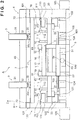
- Fig. 2 is a front view of the cutting apparatus
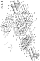
- Fig. 3 is an exploded perspective view of the cutting apparatus
- Fig. 4 is a block diagram of a controller
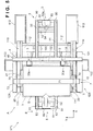
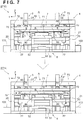
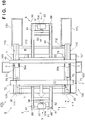
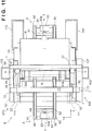
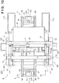
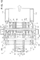
- Figs. 5 to 13 are views for explaining the operation of the cutting apparatus.
- Fig. 1 is a plan view of a cutting apparatus A according to an embodiment of the present invention.
- Fig. 2 is a front view of the cutting apparatus A.
- Fig. 3 is an exploded perspective view of the cutting apparatus A. Note that collection units 100 and 110 indicated by the broken lines in Fig. 1 are shown in a perspective view.
- arrows X and Y respectively indicate two directions perpendicular to each other in the horizontal direction, and an arrow Z indicates the vertical direction.
- the X direction coincides with the conveying direction of a substrate conveyed by convey units 8 and 9 (to be described later).
- the cutting apparatus A includes holding units 1, a moving unit 2, head units 3, a moving unit 4, convey/lifting units 5, substrate lifting units 6, a positioning unit 7, the convey units 8 and 9, and the collection units 100 and 110.
- the cutting apparatus A is an apparatus which cuts the edge portions (the portions protruding from the periphery of a rectangular substrate B (see Fig. 5 )) of a cover sheet b (see Fig. 5 ) which covers the substrate B.
- the holding units 1 hold the substrate B by chucking its one surface (the lower surface of the substrate in this embodiment).
- This embodiment is provided with a plurality of holding units 1, each of which includes a plurality of vacuum-chucking pads 10 which chuck one surface of the substrate B. All the vacuum-chucking pads 10 are positioned on the common X-Y plane (horizontal plane) and can hold a substrate in a horizontal posture.
- Each vacuum-chucking pad 10 is connected to a vacuum pump (not shown). When this vacuum pump is operated, the vacuum-chucking pads 10 chuck and hold a substrate.
- the holding units 1 are arranged along the four sides of the substrate B to hold the periphery of the substrate B. Holding the periphery of the substrate B can prevent the periphery of the substrate from swinging when cutting the cover sheet b. This makes it possible to properly cut the edge portions of the cover sheet b.
- the holding unit 1 may be disposed to hold a central portion of the substrate B.
- the moving unit 2 includes a pair of guide members 20, a moving body 21 laid between the pair of guide members 20, and driving units 22.
- the pair of guide members 20 are spaced apart from each other in the Y direction and extend parallel to the X direction.
- the moving body 21 has a frame-like shape, on which the plurality of holding units 1 are mounted and supported.
- the driving units 22 are provided on the lower surfaces of the two end portions of the moving body 21, and sliders which respectively engage with the guide members 20 to be guided by them when moving. That is, the driving units 22 constitute a moving mechanism which moves the moving body 21 along the pair of guide members 20.
- a ball screw mechanism can be used.
- the guide members 20 include ball screw shafts extending in the X direction
- the driving units 22 include ball nuts which threadably engage with the ball screw shafts and motors (for example, hollow motors) which rotate the ball nuts.
- synchronously driving the motors of the driving units 22 can translate the moving body 21 in the X direction (the transfer direction of a substrate).
- Other moving mechanisms which can be used include a rack-pinion mechanism, a toothed belt-pulley mechanism, and a linear mechanism.
- one of the two driving units 22 can be configured to be simply driven along the guide member 20 without providing any drive source such as a motor.
- the moving unit 2 moves the moving body 21 in the X direction to move the holding units 1 mounted on the moving body 21 across a transfer position and a cutting operation region which are continuous in the X direction.
- the transfer position includes a load position (the lower left position in Fig. 3 ) on one end portion of the guide members 20 and an unload position (the upper right position in Fig. 3 ) on the other end portion
- the cutting operation region is the region between the load position and the unload position. That is, in this embodiment, the cutting operation region is set to the entire moving range of the holding units 1, and its two end portions are set to the load and unload positions. This has the effect of shortening the total length of the cutting apparatus A.
- the load position is set on one of the two end portions of the guide members 20 which is located on the convey unit 8 side (one end portion side). At this position, the convey unit 8 loads the substrate B (on which the edge portions of the cover sheet b are not cut yet) onto the holding units 1.
- the unload position is set on one of the two end portions of the guide members 20 which is located on the convey unit 9 side (the other end portion). At this position, the substrate B (on which the edge portions of the cover sheet b have already been cut) is unloaded from the holding units 1 to the convey unit 9.
- the head units 3 include cutting units 30 which cut the edge portions of the cover sheet b and lifting/pivoting units 31 which move the cutting units 30 and change the cutting directions by making them pivot (rotate).
- This embodiment includes two head units 3. This can simultaneously cut edge portions of the cover sheet b at different positions, thereby improving the cutting efficiency.
- the embodiment may include only one head unit 3.
- Each cutting unit 30 includes a disc blade 30a and a driving mechanism such as a motor which rotates the disc blade 30a.
- the cutting unit 30 cuts an edge portion of the cover sheet b by rotating the disc blade 30a.
- This embodiment uses, as the cutting unit 30, a mechanism for cutting the cover sheet b by rotating the disc blade 30a.
- the mechanism to be used is not limited to this.
- the embodiment can use other types of cutting mechanisms, for example, a mechanism for cutting the cover sheet b with a fixed blade and a mechanism for cutting the cover sheet b with a laser beam.
- the lifting/pivoting units 31 include mechanisms (not shown) for rotating shaft bodies 32 about their shaft centers (Z direction) and vertically moving the shaft bodies 32.
- the cutting units 30 are coupled to the shaft bodies 32.
- the lifting/pivoting units 31 make the cutting units 30 pivot by rotating the shaft bodies 32 and can maintain their pivot angles.
- the lifting/pivoting units 31 can vertically move the cutting units 30 in the Z direction by vertically moving the shaft bodies 32.
- Changing the cutting directions by making the cutting units 30 pivot can cut the edge portions of the cover sheet b along the four sides of the substrate B.
- each cutting unit 30 can adjust the cutting blade position (height position) of the disc blade 30a relative to a plane perpendicular to a direction parallel to a direction normal to the substrate surface of the substrate B (a plane perpendicular to the Z direction in this embodiment) and a plane formed by the disc blade 30a (a plane perpendicular to the Z direction in the embodiment).
- a known mechanism can be used as a mechanism for rotating and vertically moving the shaft body 32.
- a mechanism for rotating the shaft body 32 there is available a combination of a drive source such as a motor and a mechanism such as a gear mechanism or a belt mechanism.
- a mechanism for maintaining the rotational angle of the shaft body 32 for example, it is possible to use the electromagnetic lock function of a servo motor when the servo motor is used as a drive source.
- a mechanism for vertically moving the shaft body 32 there is available a combination of a drive source such as a motor and a mechanism such as a rack-pinion mechanism.
- the moving unit 4 moves the head units 3 in the Y direction.
- the moving unit 4 incudes an guide member 40, moving bodies 41 attached to the guide member 40 so as to allow them to move along the guide member 40, and a moving mechanism (not shown) for moving the moving bodies 41 along the guide member 40.
- the guide member 40 extends in the Y direction.
- the two moving bodies 41 are provided in correspondence with the number of head units 3, and are sliders which engage with the guide member 40 and move while being guided by it.
- the guide member 40 is common to the two moving bodies 41. This can simplify the arrangement as compared with a case in which the guide member 40 is provided for each moving body 41 .
- a ball screw mechanism As a moving mechanism (not shown), for example, a ball screw mechanism is available.
- a ball screw mechanism it is possible to use an arrangement in which the guide member 40 includes a ball screw shaft extending in the Y direction, and each moving body 41 is provided with a ball nut which threadably engages with the ball screw shaft and a motor (for example, a hollow motor) which rotates the ball nut.
- each moving body 41 includes a motor, it is possible to independently move and control the moving bodies 41. This makes it possible to independently move and control the two head units 3.
- one ball screw shaft may be commonly provided for the two moving bodies 41, or may be provided for each moving body 41.
- the moving unit 4 is disposed so as to be vertically shifted from the holding units 1 within the moving range of the holding units 1 moved by the moving unit 2.
- the guide member 40 is disposed in a direction to separate from the guide members 20 vertically and intersect them. According to this arrangement, since the guide members 20 and 40 can be stacked vertically, the installation space can be effectively used. In addition, since it is possible to make the width of the moving unit 2 fall within the range of the guide member 40 in the longitudinal direction, it is possible to achieve space saving.
- the convey/lifting units 5 each are provided to support one end portion (an end portion on the side opposite to the holding units 1) of a corresponding one of belt conveyors 80 and 90 of the convey units 8 and 9, and vertically move a corresponding one of the convey units 8 and 9 at the transfer position relative to the holding units 1. This can transfer the substrate B between the holding units 1 and the convey units 8 and 9.
- the convey/lifting units 5 include support frames 51 which support the convey units 8 and 9 and guide frames 52 which support the support frames 51 so as to allow them to move in the Z direction.
- the guide frames 52 are provided with rail members extending in the Z direction.
- the support frames 51 are provided with sliders which engage with the rail members and slide in the Z direction.
- the convey/lifting units 5 include motors 53 and eccentric cams 54 provided on output shafts 53a of the motors 53.
- the circumferential surfaces of the eccentric cams 54 are in contact with the lower surfaces of the support frames 51. Rotating the eccentric cams 54 can vertically move the support frames 51 in the Z direction. This makes it possible to vertically move the convey units 8 and 9.
- the cam mechanisms using the motors 53 as drive sources vertically move the convey units 8 and 9.
- This embodiment is configured to vertically move the convey units 8 and 9. However, it is possible to vertically move the holding units 1. That is, it is possible to move either the holding units 1 or the convey units 8 and 9 as long as it is possible to vertically move them relatively to each other.
- the substrate lifting units 6 vertically move the substrate B relative to the holding units 1.
- the positioning unit 7 positions the substrate B.
- the substrate lifting units 6 move upward to separate the substrate B from the vacuum-chucking pads 10 of the holding units 1.
- the substrate lifting units 6 move the substrate B downward to mount it on the vacuum-chucking pads 10 of the holding units 1 and cause the vacuum-chucking pads 10 to hold the substrate.
- the substrate lifting units 6 are air cylinders. However, other driving mechanisms can be used.
- the positioning unit 7 positions the substrate B in the Y direction at the load position.
- the positioning unit 7 includes a pair of abutment members 70 spaced apart from each other in the Y direction, a guide member 71 which supports the pair of abutment members 70 so as to allow them to move in the Y direction, and a moving mechanism (not shown) which moves the pair of abutment members 70.
- the moving mechanism can be constituted by, for example, a drive source such as an air cylinder which moves one of the abutment members 70 and a link mechanism which interlocks the two abutment members 70.
- the pair of abutment members 70 are moved between the positioning positions at which the abutment members abut against two sides of the substrate B which face each other in the Y direction to position the substrate B and retreat positions at which the abutment members are spaced apart from each other more than at the positioning positions.
- the pair of abutment members 70 are plate-like members extending in the Y direction, and hence abut against two sides of the substrate B which face each other so as to position the substrate in the Y direction and to adjust the posture of the substrate B by making the two sides of the substrate B which face each other parallel to the Y direction while making the remaining two sides parallel to the X direction.
- both the convey units 8 and 9 are regarded as the belt conveyors 80 and 90 which respectively make endless belts 81 and 91 run in the X direction.
- the substrate B is disposed on the endless belts 81 and 91 to be conveyed.
- the convey unit 8 is used to load the substrate B.
- the convey unit 9 is used to unload the substrate B.
- the convey units 8 and 9 are regarded as belt conveyors.
- the embodiment includes both the convey units for loading and unloading. However, it is possible to use one of them.
- the convey units 8 and 9 each have a cantilever structure. That is, only one end portion of each convey unit is supported, while the other end portion (the end portion on the holding unit 1 side) has no support structure. This allows the other end portion side of each of the convey units 8 and 9 to be overlapped (superimposed), in the X direction, on the holding units 1 extending in the X direction. More specifically, the convey units 8 and 9 are provided while the other end portion side of each of the convey units 8 and 9 enters a frame member 120 (to be described later). This makes it possible to transfer the substrate B between the convey units 8 and 9 and the holding units 1.
- the collection units 100 and 110 collect the cut edge portions of the cover sheet b. This can prevent the cut edge portions of the cover sheet b from being scattered.
- the collection unit 100 includes a belt conveyor 101 disposed below the moving path of the cutting unit 30 along the guide member 40 and a pair of guide members 102 disposed on the two side portions of the belt conveyor 101.
- the belt conveyor 101 extends in the Y direction and includes an endless belt which runs in the Y direction.
- the pair of guide members 102 are obliquely disposed so as to open upward (increase in interval).
- Collection boxes 103 are respectively disposed on the two end portions (the two end portions in the Y direction) of the belt conveyor 101.
- the cutting units 30 cut edge portions of the cover sheet b along the two ends of the substrate B in the X direction
- the cut edge portions drop on the belt conveyor 101.
- the pair of guide members 102 function as chutes (slides) which guide the edge portions onto the belt conveyor 101.
- the belt conveyor 101 is operated continuously or periodically to make the endless belt run, thereby conveying the cut edge portions to the collection boxes 103.
- the collection units 110 are respectively provided along the pair of guide members 20 below the cutting units 30.
- Each collection unit 110 includes a belt conveyor 111 and a pair of guide members 112 provided on the two side portions of the belt conveyor 111.
- the belt conveyor 111 extends in the X direction and includes an endless belt which runs in the X direction.
- the pair of guide members 112 are obliquely disposed so as to open such that the interval between them increases upward.
- a collection box 113 is disposed on one end portion (one end portion in the transfer direction) of the belt conveyor 111.
- this embodiment uses the belt conveyors 101 and 111 as the collection units 100 and 110.
- the embodiment may use an arrangement including trough-like (almost U-shaped) member which receives cut pieces which are cut and drop and a suction device which sucks cut pieces in the trough and discharges them into the collection box.
- the guide members 20, the guide member 40, and collection units 100 and 110 are all integrally supported on the common frame member 120. Supporting them with the common frame member 120 can improve the positioning accuracy between them.
- the guide member 40 is laid between a pair of beam portions 121 of the frame member 120.
- the pair of beam portions 121 are spaced apart from each other in the Y direction, and each extends in the X direction.
- the guide members 20 are mounted and supported on support portions 122 of the frame member 120.
- the collection unit 100 is mounted and supported on support portions 124 of the frame member 120.
- Each collection unit 110 is mounted and supported on support portions 123 of the frame member 120.
- FIG. 4 is a block diagram of the controller 200.
- the controller 200 includes a processing unit 201 such as a CPU, a storage unit 202 such as a RAM, ROM, or hard disk, and an interface unit 203 which interfaces the processing unit 201 with an external device.
- a processing unit 201 such as a CPU
- a storage unit 202 such as a RAM, ROM, or hard disk
- an interface unit 203 which interfaces the processing unit 201 with an external device.
- the processing unit 201 executes programs based on the cutting start position and cutting end position of the moving body 21, the pivot angle of each cutting unit 30, the cutting start position and cutting end position of the head unit 3, and the like, which are stored in the storage unit 202, and controls various types of actuators 207 based on the detection results obtained by various types of sensors 206.
- the various types of sensors 206 include, for example, a sensor which detects the position of the head unit 3 in the Y direction, sensors which detect the pivot angles of the cutting units 30 and their positions in the Z direction, a sensor which detects the position of the substrate B conveyed by the convey unit 8, and sensors which detect the positions of the holding units 1 (moving body 21) in the X direction.
- the various types of actuators 207 include a vacuum pump and control valves which actuate the vacuum-chucking pads 10, drive sources such as the motors of moving mechanisms of the moving units 2 and 4, motors which rotate the disc blades 30a, a drive source for the positioning unit 7, the motors 53 of the convey/lifting units 5, and drive sources for the substrate lifting units 6.
- An input unit 204 includes a keyboard and a mouse which accept instructions from an operator.
- a display unit 205 is an image display device which displays various kinds of information.
- Figs. 5 to 13 show the operation of cutting the edge portions of a cover sheet by the cutting apparatus A when transferring the substrate B covered by the cover sheet b from the convey unit 8 to the holding units 1.
- the apparatus drives the convey unit 8 to convey the substrate B in the X direction to convey it onto the holding units 1 located at the load position.
- the belt conveyors 80 of the convey unit 8 are located at the position at which they are lifted by the convey/lifting unit 5.
- the substrate lifting units 6 have also moved upward to a position which is S lower than the substrate B but is higher than the vacuum-chucking pads 10.
- the apparatus stops driving the convey unit 8. As indicated by a state ST12 in Fig. 6 , the apparatus then lowers the belt conveyors 80 of the convey unit 8 using the convey/lifting unit 5. With this operation, the apparatus transfers the substrate B from the belt conveyors 80 to the substrate lifting units 6.
- the apparatus operates the positioning unit 7 to move the pair of abutment members 70 from the retreat position to the positioning position (a direction to approach each other in Fig. 7 ). This positions the substrate B.
- the apparatus then operates the positioning unit 7 to move the pair of abutment members 70 from the positioning position to the retreat position (a direction to separate from each other in Fig. 7 ), and operates the substrate lifting units 6 to lower the substrate B. This moves the substrate B from the substrate lifting units 6 onto the vacuum-chucking pads 10 of the holding units 1.
- the apparatus operates the respective vacuum-chucking pads 10 to hold the substrate B by chucking.
- the process then shifts to the operation of cutting the edge portions of the cover sheet b.
- the apparatus cuts the edge portions in the order of one side of the substrate B at one end portion in the X direction, two sides of two end portions in the Y direction, and one side of the other end portion in the X direction.
- the apparatus moves the substrate B to a predetermined position (the first cutting position) using the moving unit 2 to position the disc blade 30a of the cutting unit 30 to one side of the substrate B.
- the apparatus sets the position and direction (the first cutting start position) of the disc blade 30a in the Y and Z directions. It is possible to store, in the storage unit 202, various kinds of information necessary for control, which include these positions and directions, based on test results before control operation (for example, teaching results) and to perform control in accordance with the stored contents.
- States ST2 and ST3 in Fig. 8 indicate a state in which the apparatus moves the cutting unit 30 along one side (the right side in Fig. 8 ) of one end portion of the substrate B in the X direction to cut an edge portion of the cover sheet b.
- one of the two cutting units 30 cuts the edge portion of the cover sheet b along half of one side of the substrate B. More specifically, as indicated by a state ST2 in Fig. 8 , the apparatus positions one cutting unit 30 at the middle position (the first cutting start position) of one side of the substrate B. The apparatus moves the cutting unit 30 from this position in the direction indicated by the arrow in Fig. 8 (the upward direction in the state ST2 in Fig. 8 ) to cut the edge portion. At this time, the other cutting unit 30 is made to retreat to a proper position (a retreat position).
- the collection unit 100 collects the cut piece.
- the apparatus positions the other cutting unit 30 to the middle position of one side of the substrate B, and moves the cutting unit 30 in the direction indicated by the arrow in Fig. 8 (in the downward direction in the state ST3 in Fig. 8 ), thereby cutting the remaining edge portion.
- one cutting unit 30 is made to retreat to a proper position.
- the apparatus completes the cutting of the edge portion of the cover sheet b which corresponds to one side of one end portion of the substrate B in the X direction.
- the apparatus then cuts the edge portions of the cover sheet b which correspond to the two sides of the two end portions of the substrate B in the Y direction.
- the two cutting units 30 simultaneously cut the respective edge portions of the cover sheet b which correspond to the two sides of the two end portions in the Y direction.
- the apparatus cuts the edge portions from the middle position of each of the two sides of the two end portions of the substrate B in the Y direction toward one end, and then from the middle position to the other end.
- the moving unit 2 moves the holding units 1 in the X direction to position the two cutting units 30 at the middle positions (the second cutting position) of the two sides of the two end portions of the substrate B in the Y direction.
- the apparatus makes the cutting units 30 retreat to proper positions (positions at which they can operate), for example, move the cutting units 30 upward, so as not to make them interfere with the substrate B.
- the apparatus makes the cutting unit 30 pivot to change the cutting direction as indicated by an arrow d1, and positions the cutting unit 30 to a predetermined position (the second cutting start position) to start cutting an edge portion of the cover sheet b.
- the apparatus cuts half of the edge portion of the cover sheet b while moving the holding units 1 to the convey unit 8 side in the X direction using the moving unit 2.
- the collection unit 110 collects the cut piece.
- the apparatus makes the cutting unit 30 pivot to change the cutting direction.
- the apparatus After changing the cutting direction, the apparatus cuts the remaining half of the edge portion of the cover sheet b while moving the holding units 1 to the convey unit 9 side in the X direction using the moving unit 2. With the above operation, the apparatus completes the cutting of the edge portions of the cover sheet b which correspond to the two sides of the two end portions of the substrate B in the Y direction.
- the apparatus then cuts the edge portion of the cover sheet b which corresponds to one side (the left side in Fig. 12 ) of the other end portion of the substrate B in the X direction.
- the apparatus moves the substrate B to a predetermined position (the third cutting position) using the moving unit 2 so as to position one side of the substrate B to the disc blade 30a of the cutting unit 30.
- the apparatus makes the cutting unit 30 pivot to change the cutting direction, and positions it to a predetermined position (the third cutting start position). As indicated by a state ST7 in Fig.
- one of the two cutting units 30 cuts the edge portion of the cover sheet b from the middle position to one end (upward in Fig. 12 ) along half of one side of the substrate B. Thereafter, the other of the two cutting units 30 cuts the remaining half of the edge portion of the cover sheet b from the middle position to the other end.
- the collection unit 100 collects the cut piece. With the above operation, the apparatus completes the cutting of the edge portion of the cover sheet b which corresponds to one side of the other end portion of the substrate B in the X direction, thereby completing the cutting of the edge portions of the cover sheet b which correspond to all the four sides of the substrate B.
- the process then shifts to unloading operation for the substrate B.
- the moving unit 2 moves the substrate B to the unload position and releases the holding of the substrate B by the vacuum-chucking pads 10.
- the convey/lifting unit 5 provided on the convey unit 9 then raises the belt conveyors 90 from the lowered position. This transfers the substrate B from the holding units 1 to the belt conveyors 90.
- the apparatus drives the belt conveyors 90 to convey the substrate B in the X direction and transfer it to convey equipment or the like (not shown).
- the apparatus completes cutting operation for one unit.
- This embodiment can not only move the substrate B from the convey unit 8 to a position suitable for cutting the cover sheet b by using the moving unit 2 but also can relatively move the cutting units 30 and the substrate B in the X direction when cutting the edge portions of the cover sheet b which correspond to the two sides of the two end portions of the substrate B in the Y direction.
- This makes it unnecessary to use a mechanism for moving the cutting units 30 in the X direction, and can cut a cover sheet along the four sides of a rectangular substrate with a simpler arrangement.
Landscapes
- Life Sciences & Earth Sciences (AREA)
- Forests & Forestry (AREA)
- Engineering & Computer Science (AREA)
- Mechanical Engineering (AREA)
- Nonmetal Cutting Devices (AREA)
- Container, Conveyance, Adherence, Positioning, Of Wafer (AREA)
- Details Of Cutting Devices (AREA)
- Dicing (AREA)
Applications Claiming Priority (1)
| Application Number | Priority Date | Filing Date | Title |
|---|---|---|---|
| JP2011036308A JP2012171057A (ja) | 2011-02-22 | 2011-02-22 | 切断装置 |
Publications (1)
| Publication Number | Publication Date |
|---|---|
| EP2492068A1 true EP2492068A1 (de) | 2012-08-29 |
Family
ID=45581769
Family Applications (1)
| Application Number | Title | Priority Date | Filing Date |
|---|---|---|---|
| EP20120155083 Withdrawn EP2492068A1 (de) | 2011-02-22 | 2012-02-13 | Schneidvorrichtung |
Country Status (4)
| Country | Link |
|---|---|
| US (1) | US20120210839A1 (de) |
| EP (1) | EP2492068A1 (de) |
| JP (1) | JP2012171057A (de) |
| CN (1) | CN102649278A (de) |
Cited By (2)
| Publication number | Priority date | Publication date | Assignee | Title |
|---|---|---|---|---|
| CN103568060A (zh) * | 2013-11-13 | 2014-02-12 | 张家港凯航通力船用设备有限公司 | 一种密封条切割夹具 |
| CN105634191A (zh) * | 2014-10-31 | 2016-06-01 | 北京精密机电控制设备研究所 | 一种模块化的平行式机电作动器 |
Families Citing this family (12)
| Publication number | Priority date | Publication date | Assignee | Title |
|---|---|---|---|---|
| CN102825623B (zh) * | 2012-09-05 | 2014-06-25 | 晋城凤凰实业有限责任公司 | 双向拉伸塑料护帮网全自动裁网机 |
| CN104724468A (zh) * | 2013-12-24 | 2015-06-24 | 太仓北新建材有限公司 | 一种履带控制系统及其控制方法 |
| CN104385322B (zh) * | 2014-11-28 | 2016-08-17 | 苏州晟成光伏设备有限公司 | 自动换向修边机 |
| CN104475870B (zh) * | 2014-11-28 | 2017-02-22 | 苏州晟成光伏设备有限公司 | 自动对中换向修边机 |
| CN107571306A (zh) * | 2017-08-30 | 2018-01-12 | 嘉善恒兴电力建设有限公司 | 一种刚性穿墙套管分割机 |
| CN107856086B (zh) * | 2017-11-30 | 2019-04-19 | 宁波德深机械设备有限公司 | 太阳能板切割设备的工作方法 |
| CN110625668B (zh) * | 2019-09-24 | 2021-02-26 | 湖北佳悦新材料科技有限公司 | 一种塑料薄膜滚切机 |
| JP7222941B2 (ja) * | 2020-02-10 | 2023-02-15 | Towa株式会社 | 加工装置 |
| CN112911491B (zh) * | 2021-01-29 | 2022-05-06 | 重庆嘉涌电子有限公司 | 配件外皮包覆系统 |
| US20230081765A1 (en) * | 2021-09-10 | 2023-03-16 | Chun-Fu Kuo | Processing device for processing opposing edges of a flexible sheet body |
| CN114290407B (zh) * | 2022-03-09 | 2022-05-24 | 太原理工大学 | 一种碳纤维复合材料板材线锯加工设备及加工方法 |
| CN117944106B (zh) * | 2024-03-25 | 2024-06-07 | 福建福人家居科技有限公司 | 一种便于装夹的板材加工切割辅助设备 |
Citations (6)
| Publication number | Priority date | Publication date | Assignee | Title |
|---|---|---|---|---|
| JPH0749189A (ja) | 1993-08-05 | 1995-02-21 | Showa Alum Corp | 熱交換器 |
| JP2001135840A (ja) | 1999-11-08 | 2001-05-18 | Kanegafuchi Chem Ind Co Ltd | 光電変換モジュールのトリミング方法および装置 |
| JP2001320069A (ja) | 2000-05-02 | 2001-11-16 | Kanegafuchi Chem Ind Co Ltd | 光電変換モジュールのトリミング方法および装置 |
| EP2087971A2 (de) * | 2008-02-08 | 2009-08-12 | Bystronic Armatec GmbH | Schneidvorrichtung |
| WO2010000235A2 (de) * | 2008-07-01 | 2010-01-07 | Grenzebach Maschinenbau Gmbh | Verfahren und vorrichtung zum besäumen photovoltaischer module |
| EP2174784A1 (de) * | 2008-10-13 | 2010-04-14 | 3S Swiss Solar Systems AG | Verfahren zum Abtrennen eines überstehenden Abschnitts einer Schicht eines Laminats |
Family Cites Families (5)
| Publication number | Priority date | Publication date | Assignee | Title |
|---|---|---|---|---|
| JPH0749189B2 (ja) * | 1986-06-14 | 1995-05-31 | デュポン株式会社 | トリミング機 |
| JPS6332798U (de) * | 1986-08-13 | 1988-03-02 | ||
| JPH0643044B2 (ja) * | 1990-01-25 | 1994-06-08 | 株式会社平安コーポレーション | 木材加工装置における被加工物の加工方法および装置 |
| JP4235414B2 (ja) * | 2002-08-22 | 2009-03-11 | キヤノン株式会社 | シート切断装置及び記録装置 |
| CN101596723B (zh) * | 2002-11-22 | 2012-05-30 | 三星钻石工业股份有限公司 | 基板分断方法 |
-
2011
- 2011-02-22 JP JP2011036308A patent/JP2012171057A/ja active Pending
-
2012
- 2012-02-13 EP EP20120155083 patent/EP2492068A1/de not_active Withdrawn
- 2012-02-17 US US13/399,540 patent/US20120210839A1/en not_active Abandoned
- 2012-02-22 CN CN2012100418719A patent/CN102649278A/zh active Pending
Patent Citations (6)
| Publication number | Priority date | Publication date | Assignee | Title |
|---|---|---|---|---|
| JPH0749189A (ja) | 1993-08-05 | 1995-02-21 | Showa Alum Corp | 熱交換器 |
| JP2001135840A (ja) | 1999-11-08 | 2001-05-18 | Kanegafuchi Chem Ind Co Ltd | 光電変換モジュールのトリミング方法および装置 |
| JP2001320069A (ja) | 2000-05-02 | 2001-11-16 | Kanegafuchi Chem Ind Co Ltd | 光電変換モジュールのトリミング方法および装置 |
| EP2087971A2 (de) * | 2008-02-08 | 2009-08-12 | Bystronic Armatec GmbH | Schneidvorrichtung |
| WO2010000235A2 (de) * | 2008-07-01 | 2010-01-07 | Grenzebach Maschinenbau Gmbh | Verfahren und vorrichtung zum besäumen photovoltaischer module |
| EP2174784A1 (de) * | 2008-10-13 | 2010-04-14 | 3S Swiss Solar Systems AG | Verfahren zum Abtrennen eines überstehenden Abschnitts einer Schicht eines Laminats |
Cited By (2)
| Publication number | Priority date | Publication date | Assignee | Title |
|---|---|---|---|---|
| CN103568060A (zh) * | 2013-11-13 | 2014-02-12 | 张家港凯航通力船用设备有限公司 | 一种密封条切割夹具 |
| CN105634191A (zh) * | 2014-10-31 | 2016-06-01 | 北京精密机电控制设备研究所 | 一种模块化的平行式机电作动器 |
Also Published As
| Publication number | Publication date |
|---|---|
| CN102649278A (zh) | 2012-08-29 |
| JP2012171057A (ja) | 2012-09-10 |
| US20120210839A1 (en) | 2012-08-23 |
Similar Documents
| Publication | Publication Date | Title |
|---|---|---|
| EP2492068A1 (de) | Schneidvorrichtung | |
| KR101763268B1 (ko) | 반송 시스템 | |
| US6557689B2 (en) | Assembly for supporting and retaining glass sheets | |
| KR101863473B1 (ko) | 엔드 이펙터 및 기판 반송 로봇 | |
| JP2018006518A (ja) | 搬送システム | |
| TWI417822B (zh) | 面板基板搬送裝置及顯示面板模組組裝裝置 | |
| US9484234B2 (en) | Processing station for planar substrates and method for processing planar substrates | |
| CN101801815A (zh) | 基板输送系统 | |
| JP4922863B2 (ja) | 表面実装装置 | |
| CN101842302A (zh) | 基板输送装置 | |
| CN101801816B (zh) | 基板输送系统 | |
| CN106104786A (zh) | 基板搬送系统及方法 | |
| US20120152079A1 (en) | Cutting apparatus | |
| JP6045376B2 (ja) | 基板搬送装置、基板の搬送方法 | |
| EP2371475A1 (de) | Vorrichtung zur Musterung laminierter Substrate mit Führung und Rolle | |
| CN101870408B (zh) | 显示面板模块组装装置及组装方法和显示面板输送装置 | |
| CN112539727B (zh) | 检测装置 | |
| CN101374740B (zh) | 搬运机器人 | |
| CN111302065A (zh) | 一种硅片载盘推齐定位装置、载板输送系统及输送方法 | |
| JP5115850B2 (ja) | 板状ワーク垂直搬送装置 | |
| WO2009113160A1 (ja) | 基板搬送装置及び基板搬送方法 | |
| JP2016004964A (ja) | 基板搬送装置 | |
| JPS61289988A (ja) | 切断機テ−ブル | |
| JP2012182273A (ja) | ガラス基板インライン検査方法及びその装置 | |
| JP4515165B2 (ja) | 基板搬送装置および基板処理装置 |
Legal Events
| Date | Code | Title | Description |
|---|---|---|---|
| PUAI | Public reference made under article 153(3) epc to a published international application that has entered the european phase |
Free format text: ORIGINAL CODE: 0009012 |
|
| AK | Designated contracting states |
Kind code of ref document: A1 Designated state(s): AL AT BE BG CH CY CZ DE DK EE ES FI FR GB GR HR HU IE IS IT LI LT LU LV MC MK MT NL NO PL PT RO RS SE SI SK SM TR |
|
| AX | Request for extension of the european patent |
Extension state: BA ME |
|
| 17P | Request for examination filed |
Effective date: 20130121 |
|
| STAA | Information on the status of an ep patent application or granted ep patent |
Free format text: STATUS: THE APPLICATION HAS BEEN WITHDRAWN |
|
| 18W | Application withdrawn |
Effective date: 20130403 |