EP2492162A2 - Remorque - Google Patents
Remorque Download PDFInfo
- Publication number
- EP2492162A2 EP2492162A2 EP12152442A EP12152442A EP2492162A2 EP 2492162 A2 EP2492162 A2 EP 2492162A2 EP 12152442 A EP12152442 A EP 12152442A EP 12152442 A EP12152442 A EP 12152442A EP 2492162 A2 EP2492162 A2 EP 2492162A2
- Authority
- EP
- European Patent Office
- Prior art keywords
- tractor
- load
- control device
- speed
- soil profile
- Prior art date
- Legal status (The legal status is an assumption and is not a legal conclusion. Google has not performed a legal analysis and makes no representation as to the accuracy of the status listed.)
- Granted
Links
Images

Classifications
-
- B—PERFORMING OPERATIONS; TRANSPORTING
- B60—VEHICLES IN GENERAL
- B60W—CONJOINT CONTROL OF VEHICLE SUB-UNITS OF DIFFERENT TYPE OR DIFFERENT FUNCTION; CONTROL SYSTEMS SPECIALLY ADAPTED FOR HYBRID VEHICLES; ROAD VEHICLE DRIVE CONTROL SYSTEMS FOR PURPOSES NOT RELATED TO THE CONTROL OF A PARTICULAR SUB-UNIT
- B60W30/00—Purposes of road vehicle drive control systems not related to the control of a particular sub-unit, e.g. of systems using conjoint control of vehicle sub-units
- B60W30/14—Adaptive cruise control
- B60W30/143—Speed control
- B60W30/146—Speed limiting
-
- B—PERFORMING OPERATIONS; TRANSPORTING
- B60—VEHICLES IN GENERAL
- B60W—CONJOINT CONTROL OF VEHICLE SUB-UNITS OF DIFFERENT TYPE OR DIFFERENT FUNCTION; CONTROL SYSTEMS SPECIALLY ADAPTED FOR HYBRID VEHICLES; ROAD VEHICLE DRIVE CONTROL SYSTEMS FOR PURPOSES NOT RELATED TO THE CONTROL OF A PARTICULAR SUB-UNIT
- B60W30/00—Purposes of road vehicle drive control systems not related to the control of a particular sub-unit, e.g. of systems using conjoint control of vehicle sub-units
- B60W30/02—Control of vehicle driving stability
- B60W30/04—Control of vehicle driving stability related to roll-over prevention
-
- B—PERFORMING OPERATIONS; TRANSPORTING
- B60—VEHICLES IN GENERAL
- B60W—CONJOINT CONTROL OF VEHICLE SUB-UNITS OF DIFFERENT TYPE OR DIFFERENT FUNCTION; CONTROL SYSTEMS SPECIALLY ADAPTED FOR HYBRID VEHICLES; ROAD VEHICLE DRIVE CONTROL SYSTEMS FOR PURPOSES NOT RELATED TO THE CONTROL OF A PARTICULAR SUB-UNIT
- B60W50/00—Details of control systems for road vehicle drive control not related to the control of a particular sub-unit, e.g. process diagnostic or vehicle driver interfaces
- B60W50/08—Interaction between the driver and the control system
- B60W50/14—Means for informing the driver, warning the driver or prompting a driver intervention
- B60W2050/143—Alarm means
-
- B—PERFORMING OPERATIONS; TRANSPORTING
- B60—VEHICLES IN GENERAL
- B60W—CONJOINT CONTROL OF VEHICLE SUB-UNITS OF DIFFERENT TYPE OR DIFFERENT FUNCTION; CONTROL SYSTEMS SPECIALLY ADAPTED FOR HYBRID VEHICLES; ROAD VEHICLE DRIVE CONTROL SYSTEMS FOR PURPOSES NOT RELATED TO THE CONTROL OF A PARTICULAR SUB-UNIT
- B60W50/00—Details of control systems for road vehicle drive control not related to the control of a particular sub-unit, e.g. process diagnostic or vehicle driver interfaces
- B60W50/08—Interaction between the driver and the control system
- B60W50/14—Means for informing the driver, warning the driver or prompting a driver intervention
- B60W2050/146—Display means
-
- B—PERFORMING OPERATIONS; TRANSPORTING
- B60—VEHICLES IN GENERAL
- B60W—CONJOINT CONTROL OF VEHICLE SUB-UNITS OF DIFFERENT TYPE OR DIFFERENT FUNCTION; CONTROL SYSTEMS SPECIALLY ADAPTED FOR HYBRID VEHICLES; ROAD VEHICLE DRIVE CONTROL SYSTEMS FOR PURPOSES NOT RELATED TO THE CONTROL OF A PARTICULAR SUB-UNIT
- B60W2530/00—Input parameters relating to vehicle conditions or values, not covered by groups B60W2510/00 or B60W2520/00
- B60W2530/10—Weight
-
- B—PERFORMING OPERATIONS; TRANSPORTING
- B60—VEHICLES IN GENERAL
- B60W—CONJOINT CONTROL OF VEHICLE SUB-UNITS OF DIFFERENT TYPE OR DIFFERENT FUNCTION; CONTROL SYSTEMS SPECIALLY ADAPTED FOR HYBRID VEHICLES; ROAD VEHICLE DRIVE CONTROL SYSTEMS FOR PURPOSES NOT RELATED TO THE CONTROL OF A PARTICULAR SUB-UNIT
- B60W2552/00—Input parameters relating to infrastructure
- B60W2552/15—Road slope, i.e. the inclination of a road segment in the longitudinal direction
-
- B—PERFORMING OPERATIONS; TRANSPORTING
- B60—VEHICLES IN GENERAL
- B60W—CONJOINT CONTROL OF VEHICLE SUB-UNITS OF DIFFERENT TYPE OR DIFFERENT FUNCTION; CONTROL SYSTEMS SPECIALLY ADAPTED FOR HYBRID VEHICLES; ROAD VEHICLE DRIVE CONTROL SYSTEMS FOR PURPOSES NOT RELATED TO THE CONTROL OF A PARTICULAR SUB-UNIT
- B60W2552/00—Input parameters relating to infrastructure
- B60W2552/40—Coefficient of friction
-
- B—PERFORMING OPERATIONS; TRANSPORTING
- B60—VEHICLES IN GENERAL
- B60W—CONJOINT CONTROL OF VEHICLE SUB-UNITS OF DIFFERENT TYPE OR DIFFERENT FUNCTION; CONTROL SYSTEMS SPECIALLY ADAPTED FOR HYBRID VEHICLES; ROAD VEHICLE DRIVE CONTROL SYSTEMS FOR PURPOSES NOT RELATED TO THE CONTROL OF A PARTICULAR SUB-UNIT
- B60W2555/00—Input parameters relating to exterior conditions, not covered by groups B60W2552/00, B60W2554/00
- B60W2555/60—Traffic rules, e.g. speed limits or right of way
-
- B—PERFORMING OPERATIONS; TRANSPORTING
- B60—VEHICLES IN GENERAL
- B60W—CONJOINT CONTROL OF VEHICLE SUB-UNITS OF DIFFERENT TYPE OR DIFFERENT FUNCTION; CONTROL SYSTEMS SPECIALLY ADAPTED FOR HYBRID VEHICLES; ROAD VEHICLE DRIVE CONTROL SYSTEMS FOR PURPOSES NOT RELATED TO THE CONTROL OF A PARTICULAR SUB-UNIT
- B60W2556/00—Input parameters relating to data
- B60W2556/45—External transmission of data to or from the vehicle
- B60W2556/50—External transmission of data to or from the vehicle of positioning data, e.g. GPS [Global Positioning System] data
-
- B—PERFORMING OPERATIONS; TRANSPORTING
- B60—VEHICLES IN GENERAL
- B60Y—INDEXING SCHEME RELATING TO ASPECTS CROSS-CUTTING VEHICLE TECHNOLOGY
- B60Y2200/00—Type of vehicle
- B60Y2200/10—Road Vehicles
- B60Y2200/15—Fork lift trucks, Industrial trucks
Definitions
- the invention relates to a tractor with a loading area and / or a hitch for at least one trailer.
- the in-house goods transport and material flow in particular the supply of material to production lines in production plants, is usually carried out by means of trailers on which the goods to be transported, in particular by means of transport containers, pallets or lattice boxes, are transported within the production plant.
- tractors For pulling one or more of these trailers trained as tractors warehouse trucks are used, which are provided with a corresponding hitch to which one or more trailers can be attached.
- tractors have compact dimensions, can be transported safely by the transport trailer within a production plant on cramped transport routes.
- tractors are used in intralogistics in all operating areas. It travels both outside and inside areas. Gradients and gradients are completed and various loads are transported on trailers attached to the hitch and on the bed of the tractor itself.
- the driver In all applications, the driver is so far in the task of selecting the speed of the tractor so that depending on the load and soil profile safe driving and timely braking is possible, put on itself. In practice, the driver often does not have the opportunity to determine or call the complete load and / or the ground profile in order to be able to select a correspondingly safe maximum speed depending on these conditions. Therefore, too high a speed is often selected, so that an accident risk for the driver, bystanders, buildings, facilities and the assistive or to transporting goods. If too low a speed is chosen, transporting is less effective and productive than possible. In order to achieve a safe and at the same time effective transport, the drivers are often well trained.
- the present invention has for its object to provide a way to control the driving speed of a tractor depending on the load and / or soil profile.
- a tractor with a control device for limiting a driving speed of the tractor, a load detection device and / or a Bodenprofilres heard is provided, wherein the load determining device is adapted to determine the weight of a load and pass this information to the control device, the soil profile determination device is set up to determine a current soil profile and to forward this information to the control device, and the control device is set up to determine the travel speed of the tractor as a function of a load determination device determined by the load determination device To limit load and / or determined by the soil profile determining means soil profile to a maximum permissible driving speed.
- a control device for reducing or limiting and thus adapting and influencing a traveling speed of the tractor is a device which is suitable for setting a specific target value for the maximum speed of the tractor.
- the target value can be predetermined by giving an indication to an operator of the tractor.
- the target value can be predefined by intervening in the vehicle control of the tractor to adapt the driving speed.
- a load detection device is a device by which the weight of a load to be transported or forgiven can be determined.
- Loads to be transported or warped may be loads provided on the tractor itself, for example on the bed, trailers attached to the tractor (curb weight) and / or loads on one or more trailers attached.
- a load determination device may comprise, for example, a scale.
- a load determining device is arranged in one embodiment to determine the load with the aid of motor currents, an engine characteristic, the vehicle inclination and / or a traction diagram.
- a traction diagram shows the course of driving resistances and their sum and the course of the driving force as a function of the driving speed.
- the load carried by the tractor can be determined in a simple manner.
- a soil profile determination device is a device that is suitable for determining the current soil profile on which the tractor is located. Components of the soil profile may be, for example, gradients, gradients or bumps.
- the soil profiler is also configured to determine if the tractor is on a plane.
- the soil profile determination device is suitable for determining the soil profile as a function of the direction of travel of the tractor. This can be determined easily whether the tractor is on an incline or downhill, for example.
- the soil profile determining means is adapted to determine the inclination of a tractor in the direction of travel.
- the control device comprises a visual signal generator. This makes it possible to give an operator an indication of a maximum permissible speed of the tractor and / or exceeding the maximum permissible speed of the tractor without distracting other possibly located nearby people.
- a visual signaling device is a signaling device that is capable of emitting a signal that can be perceived by an operator of the tractor with one eye.
- a visual signal transmitter is a lamp or a display.
- the signal can be given for example by flashing, lighting up or changing the color of the signal generator.
- the signal can be given by the display of a maximum allowable speed in a display.
- control device comprises an acoustic signal generator. This makes it possible to give a signal to an operator regardless of the viewing direction.
- An acoustic signal transmitter is a signal transmitter which is capable of emitting a signal that can be perceived by an operator of the tractor with one ear.
- an acoustic signal transmitter is a horn or a loudspeaker.
- the control device preferably comprises an automatic system operatively connected to a travel drive. This makes it possible to limit or reduce the speed of the tractor even if an operator disregards signals.
- Such automatic is a device that can perform operations without intervention of an operator.
- the automatic is preferably set up, the To reduce or limit the driving speed of the tractor, if necessary, contrary inputs of an operator are ignored.
- the control means is arranged to determine whether the current vehicle speed exceeds the maximum permitted vehicle speed and if the maximum permissible speed is exceeded in a first step to cause the visual signal transmitter to emit a signal when thereafter the maximum permissible speed is still exceeded is always exceeded, in a second step, to cause the acoustic signal transmitter to emit a signal, and if thereafter the permissible maximum speed is still exceeded, to cause in a third step, an automatic limitation of the driving speed by the automatic.
- This makes it possible to initially give an operator control of the tractor and only then automatically intervene in the tractor control when the operator has ignored both the visual and the acoustic signal. This avoids an operator being surprised by sudden changes in speed and possibly losing his grip or placing the tractor in connection with other forklift trucks in a situation where a collision is provoked by a sudden change in speed.
- control device preferably emits a drive signal to a brake light of the tractor.
- a brake light In the automatic reduction of the vehicle speed can be generated by a brake light, a corresponding brake signal indicating the operators of subsequent trucks the braking process of the tractor.
- the load determination device is preferably set up to measure a force in a hitch, in particular a trailer hitch, of the tractor.
- the load ie the curb weight
- the load ie the curb weight
- the quotient of force and weight measured in the hitch corresponds to the sine of the slope slope.
- the weight is the force that attached to the tractor trailer together with her Exercise charge in the vertical.
- the slope is the angle between the route and a horizontal.
- an analog or incremental displacement sensor a strain gauge, a piezoresistive pressure sensor, a piezoelectric pressure sensor, a pressure sensor in the vacuum range, a frequency-analog pressure sensor, a pressure sensor with Hall element, a capacitive pressure sensor or an inductive pressure sensor on the hitch as load detection device is provided.
- the load determining device is set up to measure a force which exerts a load on a loading surface of the tractor. This makes it possible to easily determine the weight of a load located on the bed of the tractor.
- the loading surface of the tractor is mounted so that its weight rests on a pressure sensor or a strain gauge.
- the pressure sensor is preferably a piezoresistive pressure sensor, a piezoelectric pressure sensor, a pressure sensor in the vacuum region, a frequency-analogue pressure sensor, a pressure sensor with a Hall element, a capacitive pressure sensor or an inductive pressure sensor.
- an information processing device is set up to determine a weight of the load located on the loading surface of the tractor from the pressure measured by the pressure sensor or the signal detected by the strain gauge.
- the soil profile determination device has an angle sensor for determining the position of the tractor relative to the vertical.
- the current position of the tractor can be determined in a simple manner.
- an electronic inclinometer can be used.
- a height compensator a capacitive liquid tilt sensor or an electrolyte level is used.
- the soil profile determination device has a receiver for a location system for receiving position information and is set up to retrieve a section of a soil profile from a memory with the aid of the received position information.
- This allows the ground profile data to be provided in a simpler manner since it only needs to be determined once.
- positioning systems that use RFID transponders, bar code markers, optical markers, or light sources to position themselves are used.
- the position information is preferably determined by a receiver provided in the tractor of a positioning system.
- the memory is located in the tractor.
- the memory can also be located in a different location, in which case preferably both the memory and the tractor are connected to a transmitter and a receiver in order to be able to retrieve the data in a simple manner.
- control device is set up to control the travel speed of the tractor depending on the nature of the road surface. This makes it possible to determine the maximum travel speed very accurately.
- the nature of the road surface preferably includes unevenness of the road surface such as bumps.
- the nature of the road surface comprises the static friction, sliding friction and / or rolling friction which the road surface can produce in cooperation with the wheels of the tractor.
- the data on the condition of the road surface can be retrieved from a memory based on position data.
- the memory can be in the Tugboat itself or be provided at another location. If the memory is provided at a different location, preferably both the memory and the tractor are connected to a transmitter and a receiver in order to be able to retrieve the data in a simple manner.
- Stiction, sliding friction and / or rolling friction can also be determined by located in the tractor sensors. With increasing static friction coefficient or sliding friction coefficient, a higher vehicle speed can be permitted. With increasing rolling resistance coefficient, the permissible vehicle speed can be reduced.
- the FIG. 1 shows a side view of a tractor according to the invention 1.
- the tractor 1 has seen in the vehicle longitudinal direction on a front drive part 2, in which at least one steerable drive wheel 3 is arranged.
- a display 4 is arranged on the front drive part 2.
- the tractor 1 has, for example, an electric drive system with an electric traction drive.
- the traction drive comprises a arranged in the drive part 2 and not shown, with the drive wheel 3 in operative connection electric traction drive motor.
- As steering drive an electric steering motor can be provided.
- a battery compartment 5 is arranged, in which a power supply device of the electric drive system are arranged can, for example, a battery pack. Subsequent to the drive part 2 and the battery compartment 5, the tractor 1 on a driver's seat 6, which is formed in the illustrated embodiment of a standing platform 7.
- the tractor 1 may have a fuel cell as an electrical power supply unit.
- the tractor 1 may have an internal combustion engine drive system with an internal combustion engine.
- a handlebar-like operating order 8 is provided, which is arranged on the upper side of the drive part 2.
- a frame section 9 delimits the driver's seat 6.
- This rear-side frame section 9 is provided with load wheels 3a.
- the rear-side load wheels 3a may be provided as drive wheels and one or two front-side, non-driven steered wheels 3.
- the tractor 1 is equipped with a soil profile determination device 10, 11, which preferably comprises a direction of inclination sensor 10 and / or a lateral inclination sensor 11.
- the tractor 1 has a hitch designed as a trailer device 12, with which the tractor 1 can be connected to one or more trailers, not shown.
- the towing device 12 is associated with a load determination device 13, which is designed for example as a arranged in the hitch 12 capacitive pressure sensor or strain gauges.
- the tractor 1 may be provided with a loading area to transport loads.
- the position of the tractor 1 relative to a perpendicular can be determined in a simple manner. For example, can determine whether the tractor 1 is on a slope or on a slope and how strong the slope or the slope.
- a load determination device 13 for example a capacitive pressure sensor or a strain gauge, is provided in the hitch 12, the current trailer load can be determined.
- the trailer load results from the force exerted on the hitch 12 trailers on the hitch 12. This force increases by loads on the trailers and by driving on gradients.
- a control device not shown in more detail can determine a maximum permissible speed based on the data determined by the load determination device 13 and the direction of inclination sensor as soil profiler 10 and cause the display 4 to emit a visual and / or audible warning signal, for example in the form of a red Background and / or a warning tone.
- the controller further communicates with the traction drive of the tractor 11 to reduce or limit the traveling speed based on the data determined by the load determining device 13 and the heading inclination sensor as the ground profiling device 10.
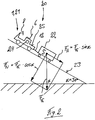
- the FIG. 2 shows a side view of a tractor train 20 on a slope.
- the tractor train 20 consists of a tractor 21 according to the invention and at least one trailer 22.
- the tractor train 20 is located on a slope 23.
- the slope distance includes with a horizontal angle ⁇ , for example, 30 °.
- a tilt angle sensor 24 is provided as a bottom profile detecting means.
- the tractor 21 has a hitch designed as a trailer device 12 with a pressure sensor, not shown.
- the trailer 22 has a trailer coupling, not shown, with which it is coupled to the hitch 12 of the tractor 21.
- the inclination angle sensor 24 designed as a soil profile determination device is set up to determine the slope of the incline path 23.
- a load determining device of the hitch 12 such as a pressure sensor or strain gauge, is arranged to determine the force which the trailer 22 exerts on the hitch 12.
- the weight F G of the trailer 22 with the transported load can be divided into two components.
- a first component F N is perpendicular to the slope distance 23 and is passed by the trailer 22 directly on the slope distance 23. This first component F N can be determined by multiplying the weight F G by the cosine of the angle ⁇ between the pitch 23 and a horizontal.
- a second component F H runs parallel to the slope section 23 and is received by the hitch 12 of the tractor 21.
- This second component F H can be determined by multiplying the weight F G by the sine of the angle ⁇ between the pitch 23 and a horizontal. By measuring this second component F H in the hitch 12 and dividing the result by the sine of the angle ⁇ between the slope distance 23 and a horizontal, which is determined by the tilt angle sensor 24, the weight force F G can be determined. With the knowledge of the vehicle inclination ⁇ , the weight force F G can also be determined from the motor currents and the motor characteristic of the drive motor, not shown, of the electric traction drive and from the traction diagram of the tractor 21.
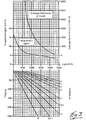
- the FIG. 3 shows an upper graph showing the permissible travel speed and distance per hour as a function of the tensile force.
- This graph shows that the permissible travel speed drops from, for example, 16.5 km / h at a pulling force of 0 N to a permissible driving speed of 3.5 km / h at a pulling force of 4500 N.
- the relationship between permissible driving speed and tractive effort is not linear over the entire range shown.
- the permissible driving speed initially drops approximately linearly to 10 km / h.
- the permissible driving speed drops to 6 km / h.
- the permissible driving speed drops again approximately linearly to 3.5 km / h.
- the permissible travel distance per hour is one Traction of 1300 N at 6000 m and decreases with increasing traction.
- the permitted distance per hour is 50 m.
- the control device of the tractor uses a predetermined delay, for example a desired deceleration of 3.5 m / sec 2 .
- the current tensile force can be determined by the load determination device 13 of the tractor 1. Thereby, the driving speed of the tractor 1, 21 are automatically limited depending on the respective tensile force. In addition, the permissible travel distance per hour can be automatically limited or reduced. Alternatively or additionally, the driver of the tractor 1, 21, the maximum permissible driving speed and / or distance per hour depending on the tensile force can be displayed. When the maximum permissible driving speed and / or driving distance per hour is exceeded, the driver can be given an acoustic and / or visual signal.
- the lower graph shows the maximum slope depending on the trailer load. In addition, it shows the relationship between slope, trailer load and traction. These relationships are shown for trailer loads of 0, 0.5 tons, 1 ton, 1.5 tons, 2 tons, 3 tons, 4 tons, 5 tons and 6 tons. An incline of 0 to 25% is shown. The theoretical tensile force that results is between 0 and 5000 N.
- the required pulling force at a 0% gradient is 0 N.
- the traction force increases linearly to about 2700 N up to a gradient of 25%.
- the traction force is at a gradient of 0% at 500 N.
- the tensile force increases linearly to about 5000 N.
- the traction force at a gradient of 0% is 1400 N.
- the traction force increases linearly to 5000 N.
- the curves are based on the assumption of a tensile force of approx. 200N per ton of trailer load.
- a gradient of 23.5% can be achieved with a trailer load of 1 t, a gradient of 18.5% with a trailer load of 1.5 t, and a gradient of 15% with a trailer load of 2 t a trailer load of 3 t a gradient of 10%, with a trailer load of 4 t a gradient of 8.5%, with a trailer load of 5 t a gradient of 7% and with a trailer load of 6 t a gradient of 5.5% be overcome.
- the maximum driving speed can be determined with known trailer load and known slope without the respective traction must be determined.
- the gradient can be determined by a direction of inclination sensor 10 or an inclination angle sensor 24 as a soil profiling device and given to the vehicle control or retrieved by means of position data from a database.
- the driving speed of the tractor 1, 21 can be automatically limited or reduced depending on the slope / gradient for a given trailer load or load on a loading platform. When the maximum permissible travel speed for a given trailer load or load on a loading platform and traveled gradient / gradient is exceeded, the driver can be given an acoustic or visual signal.
- the tractor according to the invention has a number of advantages.
- the tractor according to the invention enables an optimal driving speed, which at high Operational safety allows a high transport line. With the tractor according to the invention a safe operation is achieved with high transport performance also in a driver with low training.
Landscapes
- Engineering & Computer Science (AREA)
- Automation & Control Theory (AREA)
- Transportation (AREA)
- Mechanical Engineering (AREA)
- Control Of Driving Devices And Active Controlling Of Vehicle (AREA)
- Lifting Devices For Agricultural Implements (AREA)
- Agricultural Machines (AREA)
Priority Applications (1)
| Application Number | Priority Date | Filing Date | Title |
|---|---|---|---|
| EP20157844.0A EP3689698B2 (fr) | 2011-02-25 | 2012-01-25 | Remorqueur |
Applications Claiming Priority (1)
| Application Number | Priority Date | Filing Date | Title |
|---|---|---|---|
| DE102011012418A DE102011012418A1 (de) | 2011-02-25 | 2011-02-25 | Schlepper |
Related Child Applications (2)
| Application Number | Title | Priority Date | Filing Date |
|---|---|---|---|
| EP20157844.0A Division-Into EP3689698B2 (fr) | 2011-02-25 | 2012-01-25 | Remorqueur |
| EP20157844.0A Division EP3689698B2 (fr) | 2011-02-25 | 2012-01-25 | Remorqueur |
Publications (4)
| Publication Number | Publication Date |
|---|---|
| EP2492162A2 true EP2492162A2 (fr) | 2012-08-29 |
| EP2492162A3 EP2492162A3 (fr) | 2018-06-06 |
| EP2492162B1 EP2492162B1 (fr) | 2020-03-04 |
| EP2492162B2 EP2492162B2 (fr) | 2025-04-30 |
Family
ID=45509371
Family Applications (2)
| Application Number | Title | Priority Date | Filing Date |
|---|---|---|---|
| EP20157844.0A Active EP3689698B2 (fr) | 2011-02-25 | 2012-01-25 | Remorqueur |
| EP12152442.5A Active EP2492162B2 (fr) | 2011-02-25 | 2012-01-25 | Remorque |
Family Applications Before (1)
| Application Number | Title | Priority Date | Filing Date |
|---|---|---|---|
| EP20157844.0A Active EP3689698B2 (fr) | 2011-02-25 | 2012-01-25 | Remorqueur |
Country Status (2)
| Country | Link |
|---|---|
| EP (2) | EP3689698B2 (fr) |
| DE (1) | DE102011012418A1 (fr) |
Cited By (8)
| Publication number | Priority date | Publication date | Assignee | Title |
|---|---|---|---|---|
| EP2803618A1 (fr) * | 2013-05-18 | 2014-11-19 | Jungheinrich Aktiengesellschaft | Chariot de manutention doté d'un attelage |
| EP3147171A4 (fr) * | 2014-08-05 | 2018-01-24 | Launch Tech Company Limited | Procédé, dispositif et système pour générer des informations de guidage de comportement de conduite |
| GB2558251A (en) * | 2016-12-23 | 2018-07-11 | Caterpillar Sarl | A method of operating a work machine |
| CN113246726A (zh) * | 2020-09-22 | 2021-08-13 | 郑州嘉晨电器有限公司 | 一种基于动态规划的行驶安全控制方法 |
| WO2022111801A1 (fr) * | 2020-11-25 | 2022-06-02 | Volvo Truck Corporation | Procédé de commande d'une combinaison de véhicules |
| US11352243B2 (en) | 2018-09-13 | 2022-06-07 | Crown Equipment Corporation | System and method for controlling a maximum vehicle speed for an industrial vehicle based on a calculated load |
| CN115768673A (zh) * | 2020-07-15 | 2023-03-07 | 梅赛德斯-奔驰集团股份公司 | 用于检查目标运动轨迹是否适于车辆运动轨迹控制的方法 |
| US11619941B2 (en) * | 2017-12-21 | 2023-04-04 | Kverneland Group Mechatronics B.V. | Method for controlling a driving condition for a tractor of an agricultural machine and an agricultural machine |
Families Citing this family (4)
| Publication number | Priority date | Publication date | Assignee | Title |
|---|---|---|---|---|
| DE102011012418A1 (de) † | 2011-02-25 | 2012-08-30 | Still Gmbh | Schlepper |
| DE102016109927A1 (de) * | 2016-05-30 | 2017-11-30 | Jungheinrich Aktiengesellschaft | Vorrichtung zur Erfassung von Fahrzeugdaten |
| DE102021131677A1 (de) | 2021-12-01 | 2023-06-01 | Jungheinrich Aktiengesellschaft | System aus Flurförderzeug und Untergrund |
| DE102021214500A1 (de) | 2021-12-16 | 2023-06-22 | Zf Friedrichshafen Ag | Verfahren zur Beschränkung einer Hubanweisung für eine Hubeinrichtung eines motorgetriebenen Flurförderzeugs, Steuereinrichtung dafür und motorgetriebenes Flurförderzeug mit der Steuereinrichtung |
Family Cites Families (25)
| Publication number | Priority date | Publication date | Assignee | Title |
|---|---|---|---|---|
| DE2629360A1 (de) | 1976-06-30 | 1978-01-05 | Wagner Kg E | Flurfoerderzeug |
| DE3736807C2 (de) | 1987-10-30 | 1997-04-30 | Ulrich Trescher | Steuervorrichtung für die Bremsanlage eines Kraftfahrzeugs |
| US4942529A (en) | 1988-05-26 | 1990-07-17 | The Raymond Corporation | Lift truck control systems |
| US5070959A (en) | 1989-11-20 | 1991-12-10 | General Electric Company | Work vehicle having an electric propulsion system with adapted overspeed limit for traction motors |
| JPH05199620A (ja) | 1992-01-14 | 1993-08-06 | Toyota Autom Loom Works Ltd | トーイングトラクタの速度規制装置 |
| JP3139845B2 (ja) | 1992-07-14 | 2001-03-05 | 株式会社リコー | 画像形成装置 |
| JPH06135260A (ja) | 1992-10-23 | 1994-05-17 | Komatsu Ltd | 降坂時車速自動制御装置 |
| US5995895A (en) | 1997-07-15 | 1999-11-30 | Case Corporation | Control of vehicular systems in response to anticipated conditions predicted using predetermined geo-referenced maps |
| US6240356B1 (en) | 1998-12-23 | 2001-05-29 | Caterpillar Inc. | Work machine speed control system to manage engine overspeed and brake energy |
| US7216024B1 (en) * | 1999-07-27 | 2007-05-08 | Linde Aktiengesellschaft | Industrial truck with a stabilizing device |
| EP1212221B1 (fr) | 1999-08-24 | 2011-04-27 | Continental Teves AG & Co. oHG | Procede et dispositif de compensation de force descensionnelle |
| SE516996C2 (sv) | 2000-05-02 | 2002-04-02 | Volvo Articulated Haulers Ab | Anordning och förfarande för bestämning av maximalt tillåten hastighet hos ett fordon |
| JP2002340182A (ja) | 2001-05-14 | 2002-11-27 | Ishikawajima Shibaura Mach Co Ltd | 作業車両の車速制御機構 |
| ITTO20010905A1 (it) | 2001-09-21 | 2003-03-21 | Fiat Ricerche | Metodo e sistema per il controllo della velocita' di crociera di un autoveicolo. |
| DE10232639A1 (de) | 2002-07-18 | 2004-02-12 | Hoerbiger Antriebstechnik Gmbh | Lasttransport-Fahrzeug, insbesondere Gabelstapler |
| US6990401B2 (en) * | 2002-10-04 | 2006-01-24 | Daimlerchrysler Ag | Predictive speed control for a motor vehicle |
| US7962256B2 (en) | 2006-08-11 | 2011-06-14 | Segway Inc. | Speed limiting in electric vehicles |
| JP2008265602A (ja) | 2007-04-23 | 2008-11-06 | Xanavi Informatics Corp | 車両の速度制御システム、及び速度制御方法 |
| US8140228B2 (en) | 2009-03-27 | 2012-03-20 | The Raymond Corporation | System and method for dynamically maintaining the stability of a material handling vehicle having a vertical lift |
| DE102009022170A1 (de) | 2009-05-20 | 2010-01-14 | Daimler Ag | Verfahren zur Fahrgeschwindigkeitsregelung eines Fahrzeuges |
| US8380390B2 (en) | 2009-06-24 | 2013-02-19 | Robert Bosch Gmbh | Method and system of determining load characteristics of a trailer |
| WO2011063823A1 (fr) | 2009-11-30 | 2011-06-03 | Volvo Lastvagnar Ag | Procédé et système de commande d'un régulateur de vitesse de véhicule |
| DE102010046172B4 (de) | 2010-09-23 | 2025-07-10 | Jungheinrich Aktiengesellschaft | Verfahren zum Betreiben eines elektrisch angetriebenen Flurförderzeugs |
| DE102011012418A1 (de) † | 2011-02-25 | 2012-08-30 | Still Gmbh | Schlepper |
| GB2559170B (en) | 2017-01-30 | 2020-08-05 | Jaguar Land Rover Ltd | Apparatus and method for controlling movement of a vehicle |
-
2011
- 2011-02-25 DE DE102011012418A patent/DE102011012418A1/de not_active Ceased
-
2012
- 2012-01-25 EP EP20157844.0A patent/EP3689698B2/fr active Active
- 2012-01-25 EP EP12152442.5A patent/EP2492162B2/fr active Active
Non-Patent Citations (1)
| Title |
|---|
| None |
Cited By (14)
| Publication number | Priority date | Publication date | Assignee | Title |
|---|---|---|---|---|
| EP2803618A1 (fr) * | 2013-05-18 | 2014-11-19 | Jungheinrich Aktiengesellschaft | Chariot de manutention doté d'un attelage |
| EP3147171A4 (fr) * | 2014-08-05 | 2018-01-24 | Launch Tech Company Limited | Procédé, dispositif et système pour générer des informations de guidage de comportement de conduite |
| GB2558251A (en) * | 2016-12-23 | 2018-07-11 | Caterpillar Sarl | A method of operating a work machine |
| GB2558251B (en) * | 2016-12-23 | 2019-12-04 | Caterpillar Sarl | A method of operating a work machine |
| US11619941B2 (en) * | 2017-12-21 | 2023-04-04 | Kverneland Group Mechatronics B.V. | Method for controlling a driving condition for a tractor of an agricultural machine and an agricultural machine |
| AU2018387581B2 (en) * | 2017-12-21 | 2023-06-01 | Kverneland Group Mechatronics B.V. | A method for controlling a driving condition for a tractor of an agricultural machine and an agricultural machine |
| US11352243B2 (en) | 2018-09-13 | 2022-06-07 | Crown Equipment Corporation | System and method for controlling a maximum vehicle speed for an industrial vehicle based on a calculated load |
| US11945705B2 (en) | 2018-09-13 | 2024-04-02 | Crown Equipment Corporation | System and method for controlling a maximum vehicle speed for an industrial vehicle based on a calculated load |
| US12655004B2 (en) | 2018-09-13 | 2026-06-16 | Crown Equipment Corporation | System and method for controlling a maximum vehicle speed for an industrial vehicle based on a calculated load |
| CN115768673A (zh) * | 2020-07-15 | 2023-03-07 | 梅赛德斯-奔驰集团股份公司 | 用于检查目标运动轨迹是否适于车辆运动轨迹控制的方法 |
| CN113246726B (zh) * | 2020-09-22 | 2022-05-17 | 河南嘉晨智能控制股份有限公司 | 一种基于动态规划的行驶安全控制方法 |
| CN113246726A (zh) * | 2020-09-22 | 2021-08-13 | 郑州嘉晨电器有限公司 | 一种基于动态规划的行驶安全控制方法 |
| WO2022111801A1 (fr) * | 2020-11-25 | 2022-06-02 | Volvo Truck Corporation | Procédé de commande d'une combinaison de véhicules |
| US12545236B2 (en) | 2020-11-25 | 2026-02-10 | Volvo Truck Corporation | Method of controlling a vehicle combination |
Also Published As
| Publication number | Publication date |
|---|---|
| EP2492162B2 (fr) | 2025-04-30 |
| DE102011012418A1 (de) | 2012-08-30 |
| EP3689698A1 (fr) | 2020-08-05 |
| EP3689698C0 (fr) | 2023-06-07 |
| EP3689698B2 (fr) | 2026-03-25 |
| EP3689698B1 (fr) | 2023-06-07 |
| EP2492162B1 (fr) | 2020-03-04 |
| EP2492162A3 (fr) | 2018-06-06 |
Similar Documents
| Publication | Publication Date | Title |
|---|---|---|
| EP3689698B1 (fr) | Remorqueur | |
| EP2058190B1 (fr) | Système d'assistance à la conduite pour des combinaisons véhicule tracteur-remorque | |
| DE102013001119B4 (de) | Fahrerassistenzsystem, Verfahren für assistiertes, autonomes und/oder pilotiertes Ein- und/oder Ausparken eines Fahrzeugs, sowie Fahrzeug mit dem Fahrerassistenzsystem | |
| DE102011012407A1 (de) | Anhänger, Schlepper und daraus gebildeter Schlepperzug | |
| DE102010028911A1 (de) | Verfahren und Vorrichtung zur Überwachung einer Bewegung eines Fahrzeugs | |
| DE102007015356A1 (de) | Bestimmung der Masse eines Flugzeugs | |
| DE102009029467A1 (de) | Lastenfahrzeug mit höhenverstellbarer Hubeinrichtung | |
| DE102013011089A1 (de) | Antikollisionssystem für ein landwirtschaftliches Fahrzeug mit selbsttätiger Erkennung der Abmessungen einer Last | |
| DE102011115353A1 (de) | Bodenfreiheitsassistent für ein Kraftfahrzeug | |
| DE112018005137T5 (de) | System und verfahren für einen durch ein fahrzeug ziehbaren anhänger | |
| EP3451313A1 (fr) | Procédé de détermination d'un risque de collision | |
| EP2960128A1 (fr) | Procede destine au fonctionnement d'un vehicule automobile et vehicule automobile | |
| DE102017205513A1 (de) | Verfahren und Vorrichtung zum Einstellen einer Betriebsstrategie für ein Fahrzeug | |
| DE102011102362A1 (de) | Verfahren und Vorrichtung zur vorausschauenden Bestimmung einer geeigneten Fahrstufe | |
| DE102006059684A1 (de) | Fahrerassistenzsystem, insbesondere für Lastkraftwagen | |
| DE102005038390A1 (de) | Lenkung eines Fahrzeugs | |
| DE102011118984B4 (de) | Vorrichtung zur Messung von Last und Lastschwerpunktabstand bei einem Flurförderzeug | |
| EP3772483A1 (fr) | Procédé de détermination du mouvement propre d'un chariot de manutention | |
| DE3607135A1 (de) | Verfahren zum signalisieren der be- und ueberlastung | |
| EP2492164A2 (fr) | Chariot de manutention, en particulier remorque | |
| DE102022206053B3 (de) | Vorrichtung zur Hinderniserkennung an einem Fahrzeug mit Hubvorrichtung und Verfahren zum Betreiben einer solchen Vorrichtung | |
| EP2853452B1 (fr) | Procédé et système de commande d'un système de freinage électronique | |
| DE102019207259B4 (de) | System und Verfahren zur Absturzsicherung eines Fahrzeugs | |
| DE102018133095A1 (de) | Verfahren zur Lastbestimmung bei einem Flurförderzeug und Flurförderzeug | |
| DE102011082273A1 (de) | Gewerbliches Fahrzeug mit in Richtung nach oben sensierendem Radarsensor |
Legal Events
| Date | Code | Title | Description |
|---|---|---|---|
| PUAI | Public reference made under article 153(3) epc to a published international application that has entered the european phase |
Free format text: ORIGINAL CODE: 0009012 |
|
| AK | Designated contracting states |
Kind code of ref document: A2 Designated state(s): AL AT BE BG CH CY CZ DE DK EE ES FI FR GB GR HR HU IE IS IT LI LT LU LV MC MK MT NL NO PL PT RO RS SE SI SK SM TR |
|
| AX | Request for extension of the european patent |
Extension state: BA ME |
|
| PUAL | Search report despatched |
Free format text: ORIGINAL CODE: 0009013 |
|
| AK | Designated contracting states |
Kind code of ref document: A3 Designated state(s): AL AT BE BG CH CY CZ DE DK EE ES FI FR GB GR HR HU IE IS IT LI LT LU LV MC MK MT NL NO PL PT RO RS SE SI SK SM TR |
|
| AX | Request for extension of the european patent |
Extension state: BA ME |
|
| RIC1 | Information provided on ipc code assigned before grant |
Ipc: B60W 30/14 20060101AFI20180430BHEP Ipc: B60W 30/04 20060101ALI20180430BHEP |
|
| STAA | Information on the status of an ep patent application or granted ep patent |
Free format text: STATUS: REQUEST FOR EXAMINATION WAS MADE |
|
| 17P | Request for examination filed |
Effective date: 20181126 |
|
| RBV | Designated contracting states (corrected) |
Designated state(s): AL AT BE BG CH CY CZ DE DK EE ES FI FR GB GR HR HU IE IS IT LI LT LU LV MC MK MT NL NO PL PT RO RS SE SI SK SM TR |
|
| GRAP | Despatch of communication of intention to grant a patent |
Free format text: ORIGINAL CODE: EPIDOSNIGR1 |
|
| STAA | Information on the status of an ep patent application or granted ep patent |
Free format text: STATUS: GRANT OF PATENT IS INTENDED |
|
| INTG | Intention to grant announced |
Effective date: 20191010 |
|
| GRAS | Grant fee paid |
Free format text: ORIGINAL CODE: EPIDOSNIGR3 |
|
| GRAA | (expected) grant |
Free format text: ORIGINAL CODE: 0009210 |
|
| STAA | Information on the status of an ep patent application or granted ep patent |
Free format text: STATUS: THE PATENT HAS BEEN GRANTED |
|
| AK | Designated contracting states |
Kind code of ref document: B1 Designated state(s): AL AT BE BG CH CY CZ DE DK EE ES FI FR GB GR HR HU IE IS IT LI LT LU LV MC MK MT NL NO PL PT RO RS SE SI SK SM TR |
|
| REG | Reference to a national code |
Ref country code: GB Ref legal event code: FG4D Free format text: NOT ENGLISH |
|
| REG | Reference to a national code |
Ref country code: CH Ref legal event code: EP |
|
| REG | Reference to a national code |
Ref country code: AT Ref legal event code: REF Ref document number: 1240030 Country of ref document: AT Kind code of ref document: T Effective date: 20200315 |
|
| REG | Reference to a national code |
Ref country code: DE Ref legal event code: R096 Ref document number: 502012015825 Country of ref document: DE |
|
| REG | Reference to a national code |
Ref country code: IE Ref legal event code: FG4D Free format text: LANGUAGE OF EP DOCUMENT: GERMAN |
|
| REG | Reference to a national code |
Ref country code: NL Ref legal event code: FP |
|
| PG25 | Lapsed in a contracting state [announced via postgrant information from national office to epo] |
Ref country code: RS Free format text: LAPSE BECAUSE OF FAILURE TO SUBMIT A TRANSLATION OF THE DESCRIPTION OR TO PAY THE FEE WITHIN THE PRESCRIBED TIME-LIMIT Effective date: 20200304 Ref country code: FI Free format text: LAPSE BECAUSE OF FAILURE TO SUBMIT A TRANSLATION OF THE DESCRIPTION OR TO PAY THE FEE WITHIN THE PRESCRIBED TIME-LIMIT Effective date: 20200304 Ref country code: NO Free format text: LAPSE BECAUSE OF FAILURE TO SUBMIT A TRANSLATION OF THE DESCRIPTION OR TO PAY THE FEE WITHIN THE PRESCRIBED TIME-LIMIT Effective date: 20200604 |
|
| PG25 | Lapsed in a contracting state [announced via postgrant information from national office to epo] |
Ref country code: BG Free format text: LAPSE BECAUSE OF FAILURE TO SUBMIT A TRANSLATION OF THE DESCRIPTION OR TO PAY THE FEE WITHIN THE PRESCRIBED TIME-LIMIT Effective date: 20200604 Ref country code: HR Free format text: LAPSE BECAUSE OF FAILURE TO SUBMIT A TRANSLATION OF THE DESCRIPTION OR TO PAY THE FEE WITHIN THE PRESCRIBED TIME-LIMIT Effective date: 20200304 Ref country code: GR Free format text: LAPSE BECAUSE OF FAILURE TO SUBMIT A TRANSLATION OF THE DESCRIPTION OR TO PAY THE FEE WITHIN THE PRESCRIBED TIME-LIMIT Effective date: 20200605 Ref country code: LV Free format text: LAPSE BECAUSE OF FAILURE TO SUBMIT A TRANSLATION OF THE DESCRIPTION OR TO PAY THE FEE WITHIN THE PRESCRIBED TIME-LIMIT Effective date: 20200304 Ref country code: SE Free format text: LAPSE BECAUSE OF FAILURE TO SUBMIT A TRANSLATION OF THE DESCRIPTION OR TO PAY THE FEE WITHIN THE PRESCRIBED TIME-LIMIT Effective date: 20200304 |
|
| REG | Reference to a national code |
Ref country code: LT Ref legal event code: MG4D |
|
| PG25 | Lapsed in a contracting state [announced via postgrant information from national office to epo] |
Ref country code: SK Free format text: LAPSE BECAUSE OF FAILURE TO SUBMIT A TRANSLATION OF THE DESCRIPTION OR TO PAY THE FEE WITHIN THE PRESCRIBED TIME-LIMIT Effective date: 20200304 Ref country code: PT Free format text: LAPSE BECAUSE OF FAILURE TO SUBMIT A TRANSLATION OF THE DESCRIPTION OR TO PAY THE FEE WITHIN THE PRESCRIBED TIME-LIMIT Effective date: 20200729 Ref country code: IS Free format text: LAPSE BECAUSE OF FAILURE TO SUBMIT A TRANSLATION OF THE DESCRIPTION OR TO PAY THE FEE WITHIN THE PRESCRIBED TIME-LIMIT Effective date: 20200704 Ref country code: CZ Free format text: LAPSE BECAUSE OF FAILURE TO SUBMIT A TRANSLATION OF THE DESCRIPTION OR TO PAY THE FEE WITHIN THE PRESCRIBED TIME-LIMIT Effective date: 20200304 Ref country code: LT Free format text: LAPSE BECAUSE OF FAILURE TO SUBMIT A TRANSLATION OF THE DESCRIPTION OR TO PAY THE FEE WITHIN THE PRESCRIBED TIME-LIMIT Effective date: 20200304 Ref country code: RO Free format text: LAPSE BECAUSE OF FAILURE TO SUBMIT A TRANSLATION OF THE DESCRIPTION OR TO PAY THE FEE WITHIN THE PRESCRIBED TIME-LIMIT Effective date: 20200304 Ref country code: ES Free format text: LAPSE BECAUSE OF FAILURE TO SUBMIT A TRANSLATION OF THE DESCRIPTION OR TO PAY THE FEE WITHIN THE PRESCRIBED TIME-LIMIT Effective date: 20200304 Ref country code: EE Free format text: LAPSE BECAUSE OF FAILURE TO SUBMIT A TRANSLATION OF THE DESCRIPTION OR TO PAY THE FEE WITHIN THE PRESCRIBED TIME-LIMIT Effective date: 20200304 Ref country code: SM Free format text: LAPSE BECAUSE OF FAILURE TO SUBMIT A TRANSLATION OF THE DESCRIPTION OR TO PAY THE FEE WITHIN THE PRESCRIBED TIME-LIMIT Effective date: 20200304 |
|
| REG | Reference to a national code |
Ref country code: DE Ref legal event code: R026 Ref document number: 502012015825 Country of ref document: DE |
|
| PLBI | Opposition filed |
Free format text: ORIGINAL CODE: 0009260 |
|
| PLAX | Notice of opposition and request to file observation + time limit sent |
Free format text: ORIGINAL CODE: EPIDOSNOBS2 |
|
| 26 | Opposition filed |
Opponent name: CROWN EQUIPMENT CORPORATION Effective date: 20201204 |
|
| PG25 | Lapsed in a contracting state [announced via postgrant information from national office to epo] |
Ref country code: DK Free format text: LAPSE BECAUSE OF FAILURE TO SUBMIT A TRANSLATION OF THE DESCRIPTION OR TO PAY THE FEE WITHIN THE PRESCRIBED TIME-LIMIT Effective date: 20200304 Ref country code: IT Free format text: LAPSE BECAUSE OF FAILURE TO SUBMIT A TRANSLATION OF THE DESCRIPTION OR TO PAY THE FEE WITHIN THE PRESCRIBED TIME-LIMIT Effective date: 20200304 |
|
| PG25 | Lapsed in a contracting state [announced via postgrant information from national office to epo] |
Ref country code: PL Free format text: LAPSE BECAUSE OF FAILURE TO SUBMIT A TRANSLATION OF THE DESCRIPTION OR TO PAY THE FEE WITHIN THE PRESCRIBED TIME-LIMIT Effective date: 20200304 Ref country code: SI Free format text: LAPSE BECAUSE OF FAILURE TO SUBMIT A TRANSLATION OF THE DESCRIPTION OR TO PAY THE FEE WITHIN THE PRESCRIBED TIME-LIMIT Effective date: 20200304 |
|
| PLBB | Reply of patent proprietor to notice(s) of opposition received |
Free format text: ORIGINAL CODE: EPIDOSNOBS3 |
|
| PG25 | Lapsed in a contracting state [announced via postgrant information from national office to epo] |
Ref country code: MC Free format text: LAPSE BECAUSE OF FAILURE TO SUBMIT A TRANSLATION OF THE DESCRIPTION OR TO PAY THE FEE WITHIN THE PRESCRIBED TIME-LIMIT Effective date: 20200304 |
|
| REG | Reference to a national code |
Ref country code: CH Ref legal event code: PL |
|
| GBPC | Gb: european patent ceased through non-payment of renewal fee |
Effective date: 20210125 |
|
| PG25 | Lapsed in a contracting state [announced via postgrant information from national office to epo] |
Ref country code: LU Free format text: LAPSE BECAUSE OF NON-PAYMENT OF DUE FEES Effective date: 20210125 |
|
| PG25 | Lapsed in a contracting state [announced via postgrant information from national office to epo] |
Ref country code: LI Free format text: LAPSE BECAUSE OF NON-PAYMENT OF DUE FEES Effective date: 20210131 Ref country code: CH Free format text: LAPSE BECAUSE OF NON-PAYMENT OF DUE FEES Effective date: 20210131 Ref country code: GB Free format text: LAPSE BECAUSE OF NON-PAYMENT OF DUE FEES Effective date: 20210125 |
|
| PG25 | Lapsed in a contracting state [announced via postgrant information from national office to epo] |
Ref country code: IE Free format text: LAPSE BECAUSE OF NON-PAYMENT OF DUE FEES Effective date: 20210125 |
|
| REG | Reference to a national code |
Ref country code: AT Ref legal event code: MM01 Ref document number: 1240030 Country of ref document: AT Kind code of ref document: T Effective date: 20210125 |
|
| PG25 | Lapsed in a contracting state [announced via postgrant information from national office to epo] |
Ref country code: AT Free format text: LAPSE BECAUSE OF NON-PAYMENT OF DUE FEES Effective date: 20210125 |
|
| REG | Reference to a national code |
Ref country code: CH Ref legal event code: PK Free format text: BERICHTIGUNGEN |
|
| RIC2 | Information provided on ipc code assigned after grant |
Ipc: B60W 50/14 20200101ALI20220429BHEP Ipc: B60W 30/04 20060101ALI20220429BHEP Ipc: B60W 30/14 20060101AFI20220429BHEP |
|
| APAH | Appeal reference modified |
Free format text: ORIGINAL CODE: EPIDOSCREFNO |
|
| APBM | Appeal reference recorded |
Free format text: ORIGINAL CODE: EPIDOSNREFNO |
|
| APBP | Date of receipt of notice of appeal recorded |
Free format text: ORIGINAL CODE: EPIDOSNNOA2O |
|
| APBM | Appeal reference recorded |
Free format text: ORIGINAL CODE: EPIDOSNREFNO |
|
| APBP | Date of receipt of notice of appeal recorded |
Free format text: ORIGINAL CODE: EPIDOSNNOA2O |
|
| APBQ | Date of receipt of statement of grounds of appeal recorded |
Free format text: ORIGINAL CODE: EPIDOSNNOA3O |
|
| APBQ | Date of receipt of statement of grounds of appeal recorded |
Free format text: ORIGINAL CODE: EPIDOSNNOA3O |
|
| PG25 | Lapsed in a contracting state [announced via postgrant information from national office to epo] |
Ref country code: HU Free format text: LAPSE BECAUSE OF FAILURE TO SUBMIT A TRANSLATION OF THE DESCRIPTION OR TO PAY THE FEE WITHIN THE PRESCRIBED TIME-LIMIT; INVALID AB INITIO Effective date: 20120125 Ref country code: CY Free format text: LAPSE BECAUSE OF FAILURE TO SUBMIT A TRANSLATION OF THE DESCRIPTION OR TO PAY THE FEE WITHIN THE PRESCRIBED TIME-LIMIT Effective date: 20200304 |
|
| P01 | Opt-out of the competence of the unified patent court (upc) registered |
Effective date: 20230518 |
|
| PG25 | Lapsed in a contracting state [announced via postgrant information from national office to epo] |
Ref country code: MK Free format text: LAPSE BECAUSE OF FAILURE TO SUBMIT A TRANSLATION OF THE DESCRIPTION OR TO PAY THE FEE WITHIN THE PRESCRIBED TIME-LIMIT Effective date: 20200304 |
|
| PG25 | Lapsed in a contracting state [announced via postgrant information from national office to epo] |
Ref country code: TR Free format text: LAPSE BECAUSE OF FAILURE TO SUBMIT A TRANSLATION OF THE DESCRIPTION OR TO PAY THE FEE WITHIN THE PRESCRIBED TIME-LIMIT Effective date: 20200304 |
|
| PG25 | Lapsed in a contracting state [announced via postgrant information from national office to epo] |
Ref country code: MT Free format text: LAPSE BECAUSE OF FAILURE TO SUBMIT A TRANSLATION OF THE DESCRIPTION OR TO PAY THE FEE WITHIN THE PRESCRIBED TIME-LIMIT Effective date: 20200304 |
|
| APBU | Appeal procedure closed |
Free format text: ORIGINAL CODE: EPIDOSNNOA9O |
|
| PUAH | Patent maintained in amended form |
Free format text: ORIGINAL CODE: 0009272 |
|
| STAA | Information on the status of an ep patent application or granted ep patent |
Free format text: STATUS: PATENT MAINTAINED AS AMENDED |
|
| 27A | Patent maintained in amended form |
Effective date: 20250430 |
|
| AK | Designated contracting states |
Kind code of ref document: B2 Designated state(s): AL AT BE BG CH CY CZ DE DK EE ES FI FR GB GR HR HU IE IS IT LI LT LU LV MC MK MT NL NO PL PT RO RS SE SI SK SM TR |
|
| REG | Reference to a national code |
Ref country code: DE Ref legal event code: R102 Ref document number: 502012015825 Country of ref document: DE |
|
| REG | Reference to a national code |
Ref country code: NL Ref legal event code: FP |
|
| PGFP | Annual fee paid to national office [announced via postgrant information from national office to epo] |
Ref country code: NL Payment date: 20260121 Year of fee payment: 15 |
|
| PGFP | Annual fee paid to national office [announced via postgrant information from national office to epo] |
Ref country code: DE Payment date: 20260120 Year of fee payment: 15 |
|
| PGFP | Annual fee paid to national office [announced via postgrant information from national office to epo] |
Ref country code: BE Payment date: 20260121 Year of fee payment: 15 |
|
| PGFP | Annual fee paid to national office [announced via postgrant information from national office to epo] |
Ref country code: FR Payment date: 20260123 Year of fee payment: 15 |