EP2803618A1 - Chariot de manutention doté d'un attelage - Google Patents
Chariot de manutention doté d'un attelage Download PDFInfo
- Publication number
- EP2803618A1 EP2803618A1 EP20140168614 EP14168614A EP2803618A1 EP 2803618 A1 EP2803618 A1 EP 2803618A1 EP 20140168614 EP20140168614 EP 20140168614 EP 14168614 A EP14168614 A EP 14168614A EP 2803618 A1 EP2803618 A1 EP 2803618A1
- Authority
- EP
- European Patent Office
- Prior art keywords
- driving
- force
- drive part
- vehicle
- truck according
- Prior art date
- Legal status (The legal status is an assumption and is not a legal conclusion. Google has not performed a legal analysis and makes no representation as to the accuracy of the status listed.)
- Granted
Links
Images

Classifications
-
- B—PERFORMING OPERATIONS; TRANSPORTING
- B60—VEHICLES IN GENERAL
- B60D—VEHICLE CONNECTIONS
- B60D1/00—Traction couplings; Hitches; Draw-gear; Towing devices
- B60D1/01—Traction couplings or hitches characterised by their type
-
- B—PERFORMING OPERATIONS; TRANSPORTING
- B60—VEHICLES IN GENERAL
- B60D—VEHICLE CONNECTIONS
- B60D1/00—Traction couplings; Hitches; Draw-gear; Towing devices
- B60D1/24—Traction couplings; Hitches; Draw-gear; Towing devices characterised by arrangements for particular functions
- B60D1/248—Traction couplings; Hitches; Draw-gear; Towing devices characterised by arrangements for particular functions for measuring, indicating or displaying the weight
Definitions
- the present invention relates to an industrial truck with a drive part, which has a trailer hitch for coupling a trailer.
- the present invention relates to a towing vehicle, as used in the formation of a tugger train or a towed train.
- Previously known towed trains are formed from one or more tractors and trailers connected to them. It has been found that the higher the trailer load and the more trailers are towed in the train, the more difficult the handling of the train by the towing vehicle, in particular the deceleration. Also, the cornering stability of the towing train decreases with increasing amount and load in the towing train. In known towing vehicles, it is therefore common, if these are intended for use with many or heavily loaded trailers to throttle the maximum permissible final speed of the tractor.
- the invention has for its object to provide a truck, especially a tractor, in which throttling the final speed avoided, but nevertheless a high maximum permissible maximum speed can be achieved.
- the truck according to the invention has a drive part which has a trailer hitch for coupling a trailer.
- the trailer hitch is rigidly mounted on an adapter.
- Adapter mounted on the drive part such that an attacking on the trailer hitch, away from the drive part tensile force is detected by a force measuring device and introduced into the drive part.
- the rigid provided on the adapter hitch picks up the attacking tensile forces, ie the forward of the drive part horizontal forces and forwards them via the force measuring device in the drive part.
- the force measuring device can preferably also measure the pressure force directed to the drive part.
- the adapter is designed as a plate, on the first flat side of the trailer hitch is attached and on the opposite flat side, a pivot bearing and a connecting element are arranged.
- a pivot bearing plate is pivotally mounted on the drive part.
- a tensile force acting on the adapter can thus be introduced via the connecting element from the adapter plate into the drive part of the vehicle, wherein the tensile force is introduced and measured via the force measuring device into the drive part.
- the pivot bearing is not disposed opposite to the trailer hitch on the adapter, but offset it, a torque is exerted by the pivot bearing on the plate and thus on the connecting element.
- the connecting element is designed as a tab which can be connected to the drive part.
- a force measuring device is arranged on or on the connecting element. The force measuring device detects the part of the force which is introduced via the connecting element in the drive part of the vehicle. From the geometric conditions at the trailer hitch and the plate can be calculated back from the measured force on the tensile force.
- the force-measuring device has a display which indicates a tensile force measured on the trailer coupling.
- the indicator for the traction is preferably provided in the field of vision of the vehicle driver, so that the driver can detect the tensile force exerted on his trailing vehicle easily visible.
- a vehicle control which influences the control of the vehicle in response to measured values of the force measuring device
- driving parameters are preferably stored in the vehicle control system: maximum driving speed, maximum driving acceleration and minimum turning radius. These driving parameters influence the driving behavior of the vehicle and are adjusted depending on the measured value for the tractive force. If the towing vehicle determines that a large tractive force has to be applied, the driving parameters relevant to driving safety, such as the maximum driving force, can be determined Driving speed, the maximum acceleration and the minimum radius of curvature to be adjusted.
- the vehicle controller reduces at least one driving parameter when the measured value for the tensile force exceeds a predetermined maximum value.
- the vehicle control system allows the industrial truck according to the invention to run at a higher end speed, for example when the tractive force is low, than at a higher tractive force acting on the industrial truck. Fully loaded trailers are thus towed slower than empty trailers. Similarly, when driving against a grade, the maximum speed, the maximum acceleration and / or the minimum radius of curvature are reduced.
- a plurality of driving programs are stored in the vehicle control, in each of which one or more driving parameters are combined in a driving program, wherein the vehicle control selects one of the driving programs according to a measured value for the tractive force.
- non-predefined parameters are changed in their value, but according to the detected tractive force, a driving program with a suitable set of driving parameters is selected.
- the force measuring device measures when the vehicle is stationary and when the vehicle is dragging, wherein the traction force is determined from a change in the measured values.
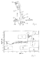
- Fig. 1 shows in a perspective view of a towing vehicle 10, which has a three-wheeled chassis 12.
- the vehicle has a standing platform 14 with a backrest 16.
- Standing on the standing platform 10 an operator can control the towing vehicle via an operating element 18.
- the direction of travel and the driving speed can be specified.
- a trailer hitch 22 is provided for a vehicle to be towed.
- Fig. 2 shows a schematic view of a possible trailer coupling 22, in which two projecting trailer plates 24, 26 are arranged opposite to each other and have a mutually aligned through hole 28.
- the trailer drawbar with an end-side eyelet (not shown) between the trailer plates 24 and 26 is arranged and fastened via a guided through the opening 28 locking bolt.
- the trailer hitch 22 is mounted on an adapter plate 30.
- the opposite side of the adapter plate 30 carries a pivot bearing 32 and a connecting plate 34.
- a strain gauge 36 is arranged as a force measuring device.
- the pivot bearing 32 is pivotally mounted via the pin 38 in a corresponding opening on the drive member.
- the adapter plate 30 is mounted substantially difficult to steer on the drive part.
- the force acting on the trailer hitch 22 tensile force Z causes the pivot bearing pivotal movement of the adapter plate.
- the adapter plate is then connected to the trailing vehicle, so that the resulting from the tensile force Z rotational movement is introduced via the connecting plate 34 in the vehicle.
- the force is conducted through the strain gauge 36 as a force measuring device, wherein the strain gauge 36 detects both the pressure forces directed towards the drive part and the traction forces pointing away from the drive part.
- a particular advantage of the illustrated adapter 30 is that it can be retrofitted to vehicles in principle. For this purpose, only a suitable abutment for the pivot bearing 32 is required and a connection for the connecting tab 34th
- Fig. 3 shows in a train with two trailers a typical course of the force occurring.
- the measuring process starts by a signal from the standing platform 14 or a seat switch as soon as the driver enters the vehicle or sits on the seat.
- This signal is a brief evaluation of the Strain gauge strip 36 started.
- the value serves as the reference value / zero value for the later measurements.
- By actuating the travel switch the measurement required to determine the load is started.
- the strain gauge 36 has a variable depending on the applied force electrical resistance, which can be detected by a suitable electrical circuit (bridge circuit). Taking into account material characteristics, the geometric measurements of tab and adapter, the strain detected on the strain gauge 36 can be converted into a corresponding force.
- Fig. 3 shows the course of force over time, at the time A, the pressing of the two trailers takes place, in which the first standing supporters set in motion.
- an emergency stop takes place at time B for abrupt deceleration of the vehicle.
- the emergency leads in C for driving the trailer on the towing vehicle.
- a force pushing the vehicle is transmitted and the vehicle comes to a standstill at time D, so that the attacking force abates abruptly.
- the stoppage of the vehicle then leads to a pendulum motion of the two trailers, which causes the change of sign of the attacking force in the time domain E.
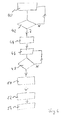
- Fig. 4 shows a flowchart in which in step 40, a system activation takes place. This is done by a query of the platform, whether it was entered or by a seat switch, if someone has taken on the seat. The initialization triggers an activation of the force measuring device for a measurement process. Also takes a brake measurement.
- step 42 the driver is queried whether an actuation of the drive switch or the accelerator pedal has occurred. If the operation is not present, the system for system activation and Referenzwertska returns in step 40. If the drive switch has been actuated, a smoothing of the measured values takes place in step 44 and a processing, for example by averaging, for a comparison. In method step 46, the smoothed and processed measured values are compared with the reference measured value from method step 40. In query 48 it is determined whether the measured values have exceeded a predetermined limit. If this is not the case, the measuring process is continued. If this is the case, then in method step 50, a driving parameter, for example the driving parameter for the maximum driving speed, is reduced.
- a driving parameter for example the driving parameter for the maximum driving speed
- step 52 the reduced driving parameter is stored in the driving control for a further control of the vehicle.
- step 54 the vehicle returns to a standby mode, from which, for example, the adaptation of the driving parameters can be repeated or monitored.
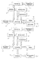
- Fig. 5 shows in a block diagram the essential process steps.
- an activation takes place, which can take place depending on the design of the truck by entering the stand platform or a seated on a seat (triggering the seat switch).
- a value of the strain gauge is recorded in method section 60.
- the value of the strain gauge is the value output by the strain gauge, which corresponds to a tensile force.
- the value of the strain gauge is reset in step 62 by selecting a present value as the zero value.
- the evaluation of the acquired measured values 60 takes place. The evaluation is triggered by actuating the travel switch or the accelerator pedal in step 66. The evaluation 64 can also use stored comparison values 68. As a result of the evaluation, the tensile force applied to the vehicle can be displayed in step 70. If a maximum permissible value for the tensile force is exceeded, a warning light can be triggered in method step 72.
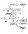
- Fig. 6 shows the sequence of a method in which takes place instead of the operation of a warning light in step 72, an intervention in the driving parameters.
- the results of the evaluation 64 are applied to a switching stage 74 which, when a predetermined maximum value for the tractive force is exceeded, reduces the driving parameter for the maximum permissible driving speed V max in method step 76.
- the trailing vehicle travels at a lower maximum speed when excessive traction over the trailer hitch acts on the vehicle.
- Fig. 7 shows a further embodiment in which in each case a different maximum travel speed V max1 , V max2 or V max3 can be selected in steps 82, 84 and 86.
- the different switching stages 74 are controlled by the comparison step 80, wherein a plurality of different comparison values 68 are present at the comparison step 80. For a better classification of the measured tensile force, the data are smoothed in step 78 before the comparison 80.
Landscapes
- Engineering & Computer Science (AREA)
- Transportation (AREA)
- Mechanical Engineering (AREA)
- Force Measurement Appropriate To Specific Purposes (AREA)
- Control Of Driving Devices And Active Controlling Of Vehicle (AREA)
Applications Claiming Priority (1)
| Application Number | Priority Date | Filing Date | Title |
|---|---|---|---|
| DE102013008705.8A DE102013008705A1 (de) | 2013-05-18 | 2013-05-18 | Flurförderzeug mit Anhängerkupplung |
Publications (2)
| Publication Number | Publication Date |
|---|---|
| EP2803618A1 true EP2803618A1 (fr) | 2014-11-19 |
| EP2803618B1 EP2803618B1 (fr) | 2017-10-25 |
Family
ID=50721690
Family Applications (1)
| Application Number | Title | Priority Date | Filing Date |
|---|---|---|---|
| EP14168614.7A Not-in-force EP2803618B1 (fr) | 2013-05-18 | 2014-05-16 | Chariot de manutention doté d'un attelage |
Country Status (2)
| Country | Link |
|---|---|
| EP (1) | EP2803618B1 (fr) |
| DE (1) | DE102013008705A1 (fr) |
Families Citing this family (6)
| Publication number | Priority date | Publication date | Assignee | Title |
|---|---|---|---|---|
| EP3379222B1 (fr) | 2017-03-22 | 2020-12-30 | Methode Electronics Malta Ltd. | Ensemble de capteur à base magnétoélastique |
| US11135882B2 (en) | 2018-02-27 | 2021-10-05 | Methode Electronics, Inc. | Towing systems and methods using magnetic field sensing |
| US11084342B2 (en) | 2018-02-27 | 2021-08-10 | Methode Electronics, Inc. | Towing systems and methods using magnetic field sensing |
| US11221262B2 (en) | 2018-02-27 | 2022-01-11 | Methode Electronics, Inc. | Towing systems and methods using magnetic field sensing |
| EP3758959B1 (fr) | 2018-02-27 | 2025-11-05 | Methode Electronics, Inc. | Systèmes et procédés de remorquage utilisant la détection magnétique |
| US11491832B2 (en) | 2018-02-27 | 2022-11-08 | Methode Electronics, Inc. | Towing systems and methods using magnetic field sensing |
Citations (2)
| Publication number | Priority date | Publication date | Assignee | Title |
|---|---|---|---|---|
| AU2008264181A1 (en) * | 2007-12-24 | 2009-07-09 | Michael Maud | Releasable Tow Hitch |
| EP2492162A2 (fr) * | 2011-02-25 | 2012-08-29 | STILL GmbH | Remorque |
Family Cites Families (5)
| Publication number | Priority date | Publication date | Assignee | Title |
|---|---|---|---|---|
| DE4419673C2 (de) * | 1994-06-07 | 1998-03-12 | Hottinger Messtechnik Baldwin | Anhängerkupplung mit einem Kraftaufnehmer |
| DE102006022744B4 (de) * | 2006-05-12 | 2015-07-16 | Linde Material Handling Gmbh | Flurförderzeug mit einer Anhängevorrichtung |
| DE102008018376A1 (de) * | 2008-04-11 | 2009-10-15 | Still Sas | Schlepper |
| US8380390B2 (en) * | 2009-06-24 | 2013-02-19 | Robert Bosch Gmbh | Method and system of determining load characteristics of a trailer |
| DE102012021352A1 (de) * | 2011-11-03 | 2013-05-08 | Westfalia-Automotive Gmbh | Anhängekupplung mit einer Auswerteeinrichtung |
-
2013
- 2013-05-18 DE DE102013008705.8A patent/DE102013008705A1/de not_active Withdrawn
-
2014
- 2014-05-16 EP EP14168614.7A patent/EP2803618B1/fr not_active Not-in-force
Patent Citations (2)
| Publication number | Priority date | Publication date | Assignee | Title |
|---|---|---|---|---|
| AU2008264181A1 (en) * | 2007-12-24 | 2009-07-09 | Michael Maud | Releasable Tow Hitch |
| EP2492162A2 (fr) * | 2011-02-25 | 2012-08-29 | STILL GmbH | Remorque |
Also Published As
| Publication number | Publication date |
|---|---|
| DE102013008705A1 (de) | 2014-11-20 |
| EP2803618B1 (fr) | 2017-10-25 |
Similar Documents
| Publication | Publication Date | Title |
|---|---|---|
| EP2803618B1 (fr) | Chariot de manutention doté d'un attelage | |
| EP2714436B1 (fr) | Ensemble pour relier un véhicule tracteur et une remorque | |
| EP0188685B1 (fr) | Installation de protection et/ou d'alarme de surcharge | |
| WO2008000558A1 (fr) | Système de réglage et de commande dans un train de véhicule | |
| DE102011003791A1 (de) | System zum automatischen Einstellen eines Spaltraumes zwischen einem Motorwagen und einem daran angekuppelten Anhänger | |
| EP2123528B1 (fr) | Combinaison de véhicule dotée d'un dispositif de frein de maintien en ligne | |
| EP2781403B1 (fr) | Dispositif et procédé de surveillance du déchargement d'un véhicule inclinable | |
| EP3515796B1 (fr) | Procédé permettant de détecter et/ou de commander une opération d'attelage entre un véhicule tracteur et une remorque de véhicule | |
| WO2023110397A1 (fr) | Procédé et dispositif de commande de l'entraînement d'un train de véhicules | |
| DE3126128A1 (de) | Anordnung zum begrenzen unkontrollierter winkelbewegungen im gelenk zwischen fahrzeugeinheiten von gelenkfahrzeugen, insbesondere gelenkomnibussen | |
| DE102018122224B4 (de) | System zur Überwachung einer Kopplung sowie eine Stützeinheit | |
| EP1612081B1 (fr) | Procédé et dispositif de fonctionnement d'un véhicule à moteur avec un attelage de remorque | |
| DE102020126622B4 (de) | Bestimmen der fahrzeug- und anhängelast | |
| EP1666280A1 (fr) | Méthode et dispositif pour distinguer entre une remorque et un dispositif porteur fixable à l'arrière du véhicule. | |
| EP2353970B1 (fr) | Guidage forcé | |
| DE4007610C2 (de) | Meß- bzw. Überwachungseinrichtung für kraftbeanspruchte Teile | |
| DE102016110836A1 (de) | Verfahren zum Vorbereiten einer Änderung eines Betriebszustands eines Gespanns, Fahrerassistenzsystem und Kraftfahrzeug | |
| EP3753758B1 (fr) | Dispositif d'accouplement pour remorques de véhicule doté d'un attelage à boule côté remorque | |
| EP2868500B1 (fr) | Système de détection d'une modification d'un réglage de géometrie d'essieu d'un véhicule automobile | |
| DE102005025851B4 (de) | Verfahren und Vorrichtung zur Erkennung einer Änderung einer Gewichtsverteilung in einem Fahrzeug | |
| EP3144646B1 (fr) | Vehicule automobile et procédé de détermination d'une force d'appui d'une roue pour chaque roue du véhicule automobile | |
| DE102020203681A1 (de) | Verfahren zum Bestimmen des Kupplungszustands zwischen zwei Fahrzeugen | |
| DE10197123B4 (de) | Verfahren und System für Bremsen von Nutzfahrzeugen | |
| WO2023227367A1 (fr) | Dispositif d'accouplement d'une remorque et/ou d'une unité porteuse de charge | |
| WO2023110344A1 (fr) | Procédé de commande de fonctions de sécurité d'un attelage de véhicule |
Legal Events
| Date | Code | Title | Description |
|---|---|---|---|
| PUAI | Public reference made under article 153(3) epc to a published international application that has entered the european phase |
Free format text: ORIGINAL CODE: 0009012 |
|
| 17P | Request for examination filed |
Effective date: 20140516 |
|
| AK | Designated contracting states |
Kind code of ref document: A1 Designated state(s): AL AT BE BG CH CY CZ DE DK EE ES FI FR GB GR HR HU IE IS IT LI LT LU LV MC MK MT NL NO PL PT RO RS SE SI SK SM TR |
|
| AX | Request for extension of the european patent |
Extension state: BA ME |
|
| R17P | Request for examination filed (corrected) |
Effective date: 20150423 |
|
| RBV | Designated contracting states (corrected) |
Designated state(s): AL AT BE BG CH CY CZ DE DK EE ES FI FR GB GR HR HU IE IS IT LI LT LU LV MC MK MT NL NO PL PT RO RS SE SI SK SM TR |
|
| GRAP | Despatch of communication of intention to grant a patent |
Free format text: ORIGINAL CODE: EPIDOSNIGR1 |
|
| STAA | Information on the status of an ep patent application or granted ep patent |
Free format text: STATUS: GRANT OF PATENT IS INTENDED |
|
| INTG | Intention to grant announced |
Effective date: 20170515 |
|
| GRAS | Grant fee paid |
Free format text: ORIGINAL CODE: EPIDOSNIGR3 |
|
| GRAA | (expected) grant |
Free format text: ORIGINAL CODE: 0009210 |
|
| STAA | Information on the status of an ep patent application or granted ep patent |
Free format text: STATUS: THE PATENT HAS BEEN GRANTED |
|
| AK | Designated contracting states |
Kind code of ref document: B1 Designated state(s): AL AT BE BG CH CY CZ DE DK EE ES FI FR GB GR HR HU IE IS IT LI LT LU LV MC MK MT NL NO PL PT RO RS SE SI SK SM TR |
|
| RAP1 | Party data changed (applicant data changed or rights of an application transferred) |
Owner name: JUNGHEINRICH AKTIENGESELLSCHAFT |
|
| REG | Reference to a national code |
Ref country code: GB Ref legal event code: FG4D Free format text: NOT ENGLISH |
|
| REG | Reference to a national code |
Ref country code: CH Ref legal event code: EP |
|
| REG | Reference to a national code |
Ref country code: AT Ref legal event code: REF Ref document number: 939708 Country of ref document: AT Kind code of ref document: T Effective date: 20171115 |
|
| REG | Reference to a national code |
Ref country code: IE Ref legal event code: FG4D Free format text: LANGUAGE OF EP DOCUMENT: GERMAN |
|
| REG | Reference to a national code |
Ref country code: DE Ref legal event code: R096 Ref document number: 502014005934 Country of ref document: DE |
|
| REG | Reference to a national code |
Ref country code: NL Ref legal event code: MP Effective date: 20171025 |
|
| REG | Reference to a national code |
Ref country code: LT Ref legal event code: MG4D |
|
| PG25 | Lapsed in a contracting state [announced via postgrant information from national office to epo] |
Ref country code: NL Free format text: LAPSE BECAUSE OF FAILURE TO SUBMIT A TRANSLATION OF THE DESCRIPTION OR TO PAY THE FEE WITHIN THE PRESCRIBED TIME-LIMIT Effective date: 20171025 |
|
| PG25 | Lapsed in a contracting state [announced via postgrant information from national office to epo] |
Ref country code: SE Free format text: LAPSE BECAUSE OF FAILURE TO SUBMIT A TRANSLATION OF THE DESCRIPTION OR TO PAY THE FEE WITHIN THE PRESCRIBED TIME-LIMIT Effective date: 20171025 Ref country code: LT Free format text: LAPSE BECAUSE OF FAILURE TO SUBMIT A TRANSLATION OF THE DESCRIPTION OR TO PAY THE FEE WITHIN THE PRESCRIBED TIME-LIMIT Effective date: 20171025 Ref country code: NO Free format text: LAPSE BECAUSE OF FAILURE TO SUBMIT A TRANSLATION OF THE DESCRIPTION OR TO PAY THE FEE WITHIN THE PRESCRIBED TIME-LIMIT Effective date: 20180125 Ref country code: FI Free format text: LAPSE BECAUSE OF FAILURE TO SUBMIT A TRANSLATION OF THE DESCRIPTION OR TO PAY THE FEE WITHIN THE PRESCRIBED TIME-LIMIT Effective date: 20171025 |
|
| REG | Reference to a national code |
Ref country code: FR Ref legal event code: PLFP Year of fee payment: 5 |
|
| PG25 | Lapsed in a contracting state [announced via postgrant information from national office to epo] |
Ref country code: HR Free format text: LAPSE BECAUSE OF FAILURE TO SUBMIT A TRANSLATION OF THE DESCRIPTION OR TO PAY THE FEE WITHIN THE PRESCRIBED TIME-LIMIT Effective date: 20171025 Ref country code: GR Free format text: LAPSE BECAUSE OF FAILURE TO SUBMIT A TRANSLATION OF THE DESCRIPTION OR TO PAY THE FEE WITHIN THE PRESCRIBED TIME-LIMIT Effective date: 20180126 Ref country code: BG Free format text: LAPSE BECAUSE OF FAILURE TO SUBMIT A TRANSLATION OF THE DESCRIPTION OR TO PAY THE FEE WITHIN THE PRESCRIBED TIME-LIMIT Effective date: 20180125 Ref country code: RS Free format text: LAPSE BECAUSE OF FAILURE TO SUBMIT A TRANSLATION OF THE DESCRIPTION OR TO PAY THE FEE WITHIN THE PRESCRIBED TIME-LIMIT Effective date: 20171025 Ref country code: LV Free format text: LAPSE BECAUSE OF FAILURE TO SUBMIT A TRANSLATION OF THE DESCRIPTION OR TO PAY THE FEE WITHIN THE PRESCRIBED TIME-LIMIT Effective date: 20171025 Ref country code: IS Free format text: LAPSE BECAUSE OF FAILURE TO SUBMIT A TRANSLATION OF THE DESCRIPTION OR TO PAY THE FEE WITHIN THE PRESCRIBED TIME-LIMIT Effective date: 20180225 |
|
| REG | Reference to a national code |
Ref country code: DE Ref legal event code: R097 Ref document number: 502014005934 Country of ref document: DE |
|
| PG25 | Lapsed in a contracting state [announced via postgrant information from national office to epo] |
Ref country code: DK Free format text: LAPSE BECAUSE OF FAILURE TO SUBMIT A TRANSLATION OF THE DESCRIPTION OR TO PAY THE FEE WITHIN THE PRESCRIBED TIME-LIMIT Effective date: 20171025 Ref country code: CY Free format text: LAPSE BECAUSE OF FAILURE TO SUBMIT A TRANSLATION OF THE DESCRIPTION OR TO PAY THE FEE WITHIN THE PRESCRIBED TIME-LIMIT Effective date: 20171025 Ref country code: EE Free format text: LAPSE BECAUSE OF FAILURE TO SUBMIT A TRANSLATION OF THE DESCRIPTION OR TO PAY THE FEE WITHIN THE PRESCRIBED TIME-LIMIT Effective date: 20171025 Ref country code: CZ Free format text: LAPSE BECAUSE OF FAILURE TO SUBMIT A TRANSLATION OF THE DESCRIPTION OR TO PAY THE FEE WITHIN THE PRESCRIBED TIME-LIMIT Effective date: 20171025 Ref country code: SK Free format text: LAPSE BECAUSE OF FAILURE TO SUBMIT A TRANSLATION OF THE DESCRIPTION OR TO PAY THE FEE WITHIN THE PRESCRIBED TIME-LIMIT Effective date: 20171025 |
|
| PG25 | Lapsed in a contracting state [announced via postgrant information from national office to epo] |
Ref country code: PL Free format text: LAPSE BECAUSE OF FAILURE TO SUBMIT A TRANSLATION OF THE DESCRIPTION OR TO PAY THE FEE WITHIN THE PRESCRIBED TIME-LIMIT Effective date: 20171025 Ref country code: IT Free format text: LAPSE BECAUSE OF FAILURE TO SUBMIT A TRANSLATION OF THE DESCRIPTION OR TO PAY THE FEE WITHIN THE PRESCRIBED TIME-LIMIT Effective date: 20171025 Ref country code: RO Free format text: LAPSE BECAUSE OF FAILURE TO SUBMIT A TRANSLATION OF THE DESCRIPTION OR TO PAY THE FEE WITHIN THE PRESCRIBED TIME-LIMIT Effective date: 20171025 Ref country code: SM Free format text: LAPSE BECAUSE OF FAILURE TO SUBMIT A TRANSLATION OF THE DESCRIPTION OR TO PAY THE FEE WITHIN THE PRESCRIBED TIME-LIMIT Effective date: 20171025 |
|
| PLBE | No opposition filed within time limit |
Free format text: ORIGINAL CODE: 0009261 |
|
| STAA | Information on the status of an ep patent application or granted ep patent |
Free format text: STATUS: NO OPPOSITION FILED WITHIN TIME LIMIT |
|
| PG25 | Lapsed in a contracting state [announced via postgrant information from national office to epo] |
Ref country code: MT Free format text: LAPSE BECAUSE OF FAILURE TO SUBMIT A TRANSLATION OF THE DESCRIPTION OR TO PAY THE FEE WITHIN THE PRESCRIBED TIME-LIMIT Effective date: 20171025 |
|
| 26N | No opposition filed |
Effective date: 20180726 |
|
| PG25 | Lapsed in a contracting state [announced via postgrant information from national office to epo] |
Ref country code: SI Free format text: LAPSE BECAUSE OF FAILURE TO SUBMIT A TRANSLATION OF THE DESCRIPTION OR TO PAY THE FEE WITHIN THE PRESCRIBED TIME-LIMIT Effective date: 20171025 |
|
| REG | Reference to a national code |
Ref country code: CH Ref legal event code: PL |
|
| REG | Reference to a national code |
Ref country code: BE Ref legal event code: MM Effective date: 20180531 |
|
| PG25 | Lapsed in a contracting state [announced via postgrant information from national office to epo] |
Ref country code: MC Free format text: LAPSE BECAUSE OF FAILURE TO SUBMIT A TRANSLATION OF THE DESCRIPTION OR TO PAY THE FEE WITHIN THE PRESCRIBED TIME-LIMIT Effective date: 20171025 |
|
| REG | Reference to a national code |
Ref country code: IE Ref legal event code: MM4A |
|
| PG25 | Lapsed in a contracting state [announced via postgrant information from national office to epo] |
Ref country code: LI Free format text: LAPSE BECAUSE OF NON-PAYMENT OF DUE FEES Effective date: 20180531 Ref country code: CH Free format text: LAPSE BECAUSE OF NON-PAYMENT OF DUE FEES Effective date: 20180531 |
|
| PG25 | Lapsed in a contracting state [announced via postgrant information from national office to epo] |
Ref country code: LU Free format text: LAPSE BECAUSE OF NON-PAYMENT OF DUE FEES Effective date: 20180516 |
|
| PG25 | Lapsed in a contracting state [announced via postgrant information from national office to epo] |
Ref country code: IE Free format text: LAPSE BECAUSE OF NON-PAYMENT OF DUE FEES Effective date: 20180516 |
|
| PG25 | Lapsed in a contracting state [announced via postgrant information from national office to epo] |
Ref country code: BE Free format text: LAPSE BECAUSE OF NON-PAYMENT OF DUE FEES Effective date: 20180531 |
|
| PG25 | Lapsed in a contracting state [announced via postgrant information from national office to epo] |
Ref country code: ES Free format text: LAPSE BECAUSE OF FAILURE TO SUBMIT A TRANSLATION OF THE DESCRIPTION OR TO PAY THE FEE WITHIN THE PRESCRIBED TIME-LIMIT Effective date: 20171025 |
|
| PG25 | Lapsed in a contracting state [announced via postgrant information from national office to epo] |
Ref country code: TR Free format text: LAPSE BECAUSE OF FAILURE TO SUBMIT A TRANSLATION OF THE DESCRIPTION OR TO PAY THE FEE WITHIN THE PRESCRIBED TIME-LIMIT Effective date: 20171025 |
|
| PG25 | Lapsed in a contracting state [announced via postgrant information from national office to epo] |
Ref country code: PT Free format text: LAPSE BECAUSE OF FAILURE TO SUBMIT A TRANSLATION OF THE DESCRIPTION OR TO PAY THE FEE WITHIN THE PRESCRIBED TIME-LIMIT Effective date: 20171025 Ref country code: HU Free format text: LAPSE BECAUSE OF FAILURE TO SUBMIT A TRANSLATION OF THE DESCRIPTION OR TO PAY THE FEE WITHIN THE PRESCRIBED TIME-LIMIT; INVALID AB INITIO Effective date: 20140516 |
|
| PG25 | Lapsed in a contracting state [announced via postgrant information from national office to epo] |
Ref country code: MK Free format text: LAPSE BECAUSE OF NON-PAYMENT OF DUE FEES Effective date: 20171025 |
|
| PG25 | Lapsed in a contracting state [announced via postgrant information from national office to epo] |
Ref country code: AL Free format text: LAPSE BECAUSE OF FAILURE TO SUBMIT A TRANSLATION OF THE DESCRIPTION OR TO PAY THE FEE WITHIN THE PRESCRIBED TIME-LIMIT Effective date: 20171025 |
|
| PGFP | Annual fee paid to national office [announced via postgrant information from national office to epo] |
Ref country code: FR Payment date: 20200527 Year of fee payment: 7 |
|
| REG | Reference to a national code |
Ref country code: AT Ref legal event code: MM01 Ref document number: 939708 Country of ref document: AT Kind code of ref document: T Effective date: 20190516 |
|
| PGFP | Annual fee paid to national office [announced via postgrant information from national office to epo] |
Ref country code: GB Payment date: 20200528 Year of fee payment: 7 |
|
| PGFP | Annual fee paid to national office [announced via postgrant information from national office to epo] |
Ref country code: DE Payment date: 20200728 Year of fee payment: 7 |
|
| PG25 | Lapsed in a contracting state [announced via postgrant information from national office to epo] |
Ref country code: AT Free format text: LAPSE BECAUSE OF NON-PAYMENT OF DUE FEES Effective date: 20190516 |
|
| REG | Reference to a national code |
Ref country code: DE Ref legal event code: R119 Ref document number: 502014005934 Country of ref document: DE |
|
| GBPC | Gb: european patent ceased through non-payment of renewal fee |
Effective date: 20210516 |
|
| PG25 | Lapsed in a contracting state [announced via postgrant information from national office to epo] |
Ref country code: GB Free format text: LAPSE BECAUSE OF NON-PAYMENT OF DUE FEES Effective date: 20210516 Ref country code: DE Free format text: LAPSE BECAUSE OF NON-PAYMENT OF DUE FEES Effective date: 20211201 |
|
| PG25 | Lapsed in a contracting state [announced via postgrant information from national office to epo] |
Ref country code: FR Free format text: LAPSE BECAUSE OF NON-PAYMENT OF DUE FEES Effective date: 20210531 |