EP2492948B1 - Röntgenstrahlgenerator - Google Patents
Röntgenstrahlgenerator Download PDFInfo
- Publication number
- EP2492948B1 EP2492948B1 EP12003029.1A EP12003029A EP2492948B1 EP 2492948 B1 EP2492948 B1 EP 2492948B1 EP 12003029 A EP12003029 A EP 12003029A EP 2492948 B1 EP2492948 B1 EP 2492948B1
- Authority
- EP
- European Patent Office
- Prior art keywords
- conductive
- anticathode
- brush
- rotary
- case
- Prior art date
- Legal status (The legal status is an assumption and is not a legal conclusion. Google has not performed a legal analysis and makes no representation as to the accuracy of the status listed.)
- Ceased
Links
- 229920001410 Microfiber Polymers 0.000 claims description 48
- 239000003658 microfiber Substances 0.000 claims description 48
- 239000000835 fiber Substances 0.000 claims description 46
- 239000000498 cooling water Substances 0.000 claims description 13
- 230000002093 peripheral effect Effects 0.000 claims description 13
- XLYOFNOQVPJJNP-UHFFFAOYSA-N water Substances O XLYOFNOQVPJJNP-UHFFFAOYSA-N 0.000 claims description 12
- 238000001816 cooling Methods 0.000 claims description 7
- 238000005342 ion exchange Methods 0.000 claims description 5
- 238000005096 rolling process Methods 0.000 claims description 5
- 229920002972 Acrylic fiber Polymers 0.000 claims description 3
- OMZSGWSJDCOLKM-UHFFFAOYSA-N copper(II) sulfide Chemical compound [S-2].[Cu+2] OMZSGWSJDCOLKM-UHFFFAOYSA-N 0.000 claims description 3
- 239000011810 insulating material Substances 0.000 claims description 3
- 238000005260 corrosion Methods 0.000 description 11
- 230000007797 corrosion Effects 0.000 description 11
- 125000006850 spacer group Chemical group 0.000 description 9
- 230000001965 increasing effect Effects 0.000 description 8
- 239000003507 refrigerant Substances 0.000 description 7
- 208000035874 Excoriation Diseases 0.000 description 6
- 238000005299 abrasion Methods 0.000 description 6
- 239000000843 powder Substances 0.000 description 6
- 239000000919 ceramic Substances 0.000 description 4
- 238000000638 solvent extraction Methods 0.000 description 4
- 239000002826 coolant Substances 0.000 description 3
- 230000003247 decreasing effect Effects 0.000 description 3
- 238000005549 size reduction Methods 0.000 description 3
- 229910000831 Steel Inorganic materials 0.000 description 2
- 239000004020 conductor Substances 0.000 description 2
- 239000010959 steel Substances 0.000 description 2
- OKTJSMMVPCPJKN-UHFFFAOYSA-N Carbon Chemical compound [C] OKTJSMMVPCPJKN-UHFFFAOYSA-N 0.000 description 1
- 229910052799 carbon Inorganic materials 0.000 description 1
- 238000010000 carbonizing Methods 0.000 description 1
- 230000015556 catabolic process Effects 0.000 description 1
- 230000007423 decrease Effects 0.000 description 1
- 230000000694 effects Effects 0.000 description 1
- 238000010894 electron beam technology Methods 0.000 description 1
- 230000002708 enhancing effect Effects 0.000 description 1
- 238000004519 manufacturing process Methods 0.000 description 1
- 238000000034 method Methods 0.000 description 1
- 239000002245 particle Substances 0.000 description 1
Images


Classifications
-
- H—ELECTRICITY
- H01—ELECTRIC ELEMENTS
- H01J—ELECTRIC DISCHARGE TUBES OR DISCHARGE LAMPS
- H01J35/00—X-ray tubes
- H01J35/24—Tubes wherein the point of impact of the cathode ray on the anode or anticathode is movable relative to the surface thereof
- H01J35/26—Tubes wherein the point of impact of the cathode ray on the anode or anticathode is movable relative to the surface thereof by rotation of the anode or anticathode
-
- H—ELECTRICITY
- H01—ELECTRIC ELEMENTS
- H01J—ELECTRIC DISCHARGE TUBES OR DISCHARGE LAMPS
- H01J2235/00—X-ray tubes
- H01J2235/10—Drive means for anode (target) substrate
- H01J2235/1046—Bearings and bearing contact surfaces
Definitions
- the present invention relates to an X-ray generator of a rotary anticathode type, and particularly to an X-ray generator which can eliminate a negative impact of electric corrosion.
- Document US 2006/0013364 A1 discloses a rotating anode x-ray tube and x-ray generator.
- a coolant passage is formed inside the rotary shaft while an air passage is formed inside the casing.
- a mechanical seal is arranged between the coolant passage and the air passage.
- Leakage cooling water which has leaked in the form of vapor from the mechanical seal, is relegated radially outwardly along with air by the action of a rotary vane, which is disposed in the air passage, and finally flows out of an air outlet.
- a coolant sensor may be provided to early detect the leakage water.
- Document US 2005/0280329 A1 discloses an electrical contact technology and methodology for the manufacture of large-diameter electrical slip rings.
- the document relates to a slip ring that is adapted to provide electrical contact between a rotor and stator.
- a brush tube is crimped around the upper marginal end portions of a plurality of individual fibers inserted therein.
- a collimator tube extends downwardly beyond the end of the brush tube to limit lateral movement of the fibers in the bundle when the rotor rotates.
- a spring is arranged to bear against a current-carrying conductor to adjustably vary the force by which the lower ends of the fibers are urged to move toward the rotor.
- Document EP 0 487 046 A2 discloses an image forming apparatus comprising: an image bearing member; an image forming means for forming a toner image on the image bearing member, the average volume particle diameter of toner being 3-10 ⁇ m; a movable transfer sheet bearing means for bearing a transfer sheet; and a transfer member for transferring the toner image formed on the image bearing member onto the transfer sheet carried by the transfer sheet bearing means at a transfer station, the transfer member comprising a fiber brush engageable by the transfer sheet bearing means at a side opposite to the image bearing member at the transfer station.
- FIG. 5 shows an X-ray generator of a rotary anticathode type disclosed in Japanese Patent Application Laid-Open No. 7-192665 .
- designation numeral 1 indicates a rotary anticathode
- designation numeral 2 indicates an anticathode accommodating case
- designation numeral 3 indicates an electric motor.
- the rotary anticathode 1 has a hollow anticathode part 1a for generating an X-ray 5 from an anticathode surface 1c, which is parallel to a rotating shaft, by collision of thermoelectrons emitted from an electron gun 4, and a hollow cylindrical shaft part 1b that continues from this anticathode part 1a. Then, a water-cooled jacket 7 is formed by a partitioning member 6 which is formed into a cylindrical shape concentric with this rotary anticathode 1.
- a space between the partitioning member 6 and the rotary anticathode 1 is set as a refrigerant feed path, and an inside of the partitioning member 6 is set as a refrigerant discharge path, and the refrigerant is flown through this water-cooled jacket 7 as shown by arrow.
- the anticathode accommodating case 2 includes an air-tight case part 2a and a journaling case part 2b.
- the air-tight case part 2a keeps an area surrounding the rotary anticathode part 1a and the electron gun 4 in a vacuum atmosphere.
- the journaling case part 2b rotatably supports the rotary anticathode 1 via a bearing 8 fitted onto the shaft part 1b
- the air-tight case part 2a is equipped, at a predetermined position, with an X-ray transmissive window which transmits a line-shaped X-ray 5 emitted from the rotary anticathode part 1a.
- a rear end portion (right end portion in FIG.
- journaling case part 2b is connected to the end portion of a partitioning member 7 in a liquid-tight manner. Further, as illustrated in the figure, a refrigerant feeding port 2d for communicating with a refrigerant feed path 7a is provided at a position closer to the rear end portion of the journaling case part 2b.
- the electric motor 3 drives by rotating the rotary anticathode 1.
- the electric motor 3 is configured such that: a rotor 3a serving as an outputting portion of torque is fixed to the vicinity of the outer peripheral portion of the rotary anticathode part 1a; a coil portion 3b for rotating the rotor 3a is fixed to an annular portion 2c provided projecting from the journaling case part 2b, and the rotor 3a is arranged so as to surround the outer periphery of the coil portion 3b. Note that, in FIG.
- Reference Numeral 9a denotes an air-tight seal (vacuum seal) for keeping the inside of the air-tight case part 2a in a vacuum state
- Reference Numeral 9b denotes a liquid-tight seal (water seal) which prevents the refrigerant from flowing into the bearing 8 side and the electric motor 3 side.
- a brush unit is arranged between a rotating portion and a fixed portion, so as to cause current to flow from the rotating portion to the fixed portion via the brush unit.
- a ceramic bearing is used as an anti-electric corrosion bearing (for example, see Japanese Patent Application Laid-Open No. 8-106870 ).
- the conventional brush unit is of a type which presses a contact piece to the outer periphery of a shaft part of a rotating body by means of pressure of a spring, which is likely to leads to a short service life due to wear.
- oxides become likely to be generated due to electric corrosion in cooling water.
- the oxides can adhere to a portion such as a refrigerant passage portion (portion shown by Numeral P in FIG. 5 ) which has been designed narrower in order to enhance cooling efficiency. As a result, cooling efficiency decreases greatly, which may cause a phenomenon in which a surface of the rotary anticathode part 1a gets rough or melted.
- the amount of wear of the contact piece was 2. 5 mm/1000 hours in an endurance test. It means that the service life of a contact piece with thickness of 5 mm ends at 2000 hours.
- an object of the present invention to provide an X-ray generator which enables eliminating a negative impact of electric corrosion as much as possible so as to increase durability, and resolving a negative impact of generated abrasion powders on a bearing, seal, or the like, and rotational loss caused by frictional resistance, so as to greatly increase the rotational speed of a rotary anticathode, and thereby to increase output of X-ray.
- the invention according to a first aspect of the present invention relates to an X-ray generator including: a rotary anticathode having an rotary anticathode part for generating an X-ray by means of collision of thermal electrons and a shaft part provided coaxially with the rotary anticathode part; an anticathode accommodating case including an air-tight case part for keeping an area surrounding the rotary anticathode part in a vacuum atmosphere, and a journaling case part for rotatively supporting the shaft part via a bearing; and an electric motor for driving by rotating the rotary anticathode, in which the rotary anticathode comprising therein a water-cooled jacket which causes cooling water for cooling the rotary anticathode part and the shaft part to flow.
- an insulating bearing of which at least one of an inner ring, an outer ring and a rolling element is made of an insulating material is used as the bearing, and a conductive fiber brush having a large number of conductive microfibers serving as slide-contacting brush is arranged between the anticathode accommodating case and the rotary anticathode, such that current is flown from the rotary anticathode to the anticathode accommodating case via the conductive fiber brush, wherein each of the conductive microfibers is a conductive fine filament made by bonding several micron-sized microfiber which is carbonized acrylic fiber with copper sulfide.
- the invention according to a second aspect of the present invention according to the first aspect relates to the X-ray generator, wherein the conductive fiber brush is arranged between a peripheral surface of the journaling case part of the anticathode accommodating case and a peripheral surface of the shaft part of the rotary anticathode, with both peripheral surfaces being opposed to each other.
- the invention according to a third aspect of the present invention according to the second aspect relates to the X-ray generator, wherein the conductive fiber brush includes: a conductive ring fitted into an inner periphery of the journaling case part; and a large number of the conductive microfibers, each base end thereof being supported by an inner periphery of the conductive ring in a brush-like shape and each distal end thereof being in soft contact with an outer periphery of the shaft part of the rotary anticathode.
- the invention according to a fourth aspect of the present invention according to the second aspect relates to the X-ray generator, wherein the conductive fiber brush includes: a conductive ring fitted into an outer periphery of the shaft part of the rotary anticathode; and a large number of the conductive microfibers, each base end thereof being supported by an outer periphery of the conductive ring in a brush-like shape and each distal end thereof being in soft contact with an inner periphery of the journaling case part.
- the invention according to a fifth aspect of the present invention according to the second aspect relates to the X-ray generator, wherein the conductive fiber brush includes: a pair of conductive rings which are provided respectively on an outer periphery of the shaft part of the rotary anticathode and on an inner periphery of the journaling case part, with mutual end surfaces opposed to each other in the axial direction; and a large number of the conductive microfibers, each base end thereof being supported by the opposed end surface of one of the pair of conductive rings in a brush-like shape, and each distal end thereof being in soft contact with the opposed end surface of the other conductive ring.
- the invention according to a sixth aspect of the present invention according to any one of the first to fifth aspects relates to the X-ray generator, pure water or ion-exchange water having low electric conductivity is used as cooling water flown through the water-cooled jacket.
- the conductive fiber brush having a large number of the conductive microfibers serving as slide-contacting brush is arranged between the anticathode accommodating case and the rotary anticathode, such that current is flown from the rotary anticathode to the anticathode accommodating case via the conductive fiber brush of a conductive microfiber type. Accordingly, unlike the conventional case where a contact piece is made in slidable contact with the outer periphery of the shaft part by means of a force of a spring, the conductive microfibers serving as a slide-contacting brush can be brought into a slidable contact with a slidable surface on the counterpart side, in the state where substantially no pressure is applied thereto.
- the insulating bearing is employed as the bearing for rotataively supporting the rotary anticathode. Therefore, let alone a problem of electric corrosion of the bearing, a problem of decreased cooling efficiency caused by oxides generated in cooling water because of electric corrosion can be effectively resolved.
- the conductive microfibers of the conductive fiber brush are substantially free from wear, and there is no temperature increase due to frictional heat. Therefore, the conductive microfibers are compatible with the substantially increased rotational speed of the rotary anticathode, thereby to enable increasing output and brightness of X-ray. Furthermore, there is neither risk of temperature increase due to frictional heat, nor risk of generation of abrasion powders. Therefore, such a problem that temperature increase or generation of abrasion powders would negatively affect the bearing or seals will not occur. In addition, substantially no frictional resistance is generated between the conductive microfibers and the slidable contact surface on the counterpart side. Therefore, rotational loss caused by the conductive fiber brush can be eliminated, thereby to contribute to the size reduction of the electric motor.
- the conductive fiber brush is arranged between a peripheral surface of the journaling case part of the anticathode accommodating case and a peripheral surface of the shaft part of the rotary anticathode, with both peripheral surfaces being opposed to each other. Accordingly, the conductive fiber brush can be incorporated without causing a problem in terms of a space.
- the conductive fiber brush includes: a conductive ring fitted into an inner periphery of the journaling case part; and a large number of the conductive microfibers, each base end thereof being supported by an inner periphery of the conductive ring in a brush-like shape and each distal end thereof being in soft contact with an outer periphery of the shaft part of the rotary anticathode. Therefore, the conductive fiber brush can be easily incorporated between the rotary anticathode and the anticathode accommodating case.
- the conductive fiber brush includes: a conductive ring fitted into an outer periphery of the shaft part of the rotary anticathode; and a large number of the conductive microfibers, each base end thereof being supported by an outer periphery of the conductive ring in a brush-like shape and each distal end thereof being in soft contact with an inner periphery of the journaling case part. Accordingly, the conductive fiber brush can be easily incorporated between the rotary anticathode and the anticathode accommodating case.
- the conductive fiber brush includes: a pair of conductive rings which are provided respectively on an outer periphery of the shaft part of the rotary anticathode and on an inner periphery of the journaling case part, with mutual end surfaces opposed to each other in the axial direction; and a large number of the conductive microfibers, each base end thereof being supported by the opposed end surface of one of the pair of conductive rings in a brush-like shape, and each distal end thereof being in soft contact with the opposed end surface of the other conductive ring. Accordingly, the conductive fiber brush can be easily incorporated between the rotary anticathode and the anticathode accommodating case.
- pure water or ion-exchange water having low electric conductivity is used as cooling water flown through the water-cooled jacket. Therefore, it is possible to prevent oxides from being generated in the cooling water more reliably.
- FIG. 1 is a sectional view of an X-ray generator according to an embodiment
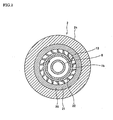
- FIG. 2 is a sectional view in the direction of the arrow II-II in FIG. 1 .
- the X-ray generator according to the present embodiment shown in FIGS. 1 and 2 differs from a conventional X-ray generator shown in FIG. 5 in the following three points. Since the other of the structure is the same as that of the X-ray generator shown in FIG. 5 , the same reference numeral is used to denote the same element, and further description thereof will be omitted.
- the insulating bearing 18 is positioned in the axial direction by sleeve-shaped spacers 12, 13 made of a conductive material fitted into the outer periphery of the shaft part 1b of the rotary anticathode 1, and distal ends of the conductive microfibers 22 of the conductive fiber brush 20 are in contact with the outer periphery of the sleeve-shaped spacer 13.
- the conductive fiber brush 20 includes a conductive ring 21 and a large number of the conductive microfibers 22.
- the conductive ring 21 is fitted into the inner periphery of the journaling case part 2b.
- each conductive microfiber 22 is supported by the inner periphery of the conductive ring 21 in a brush-like shape, and a distal end thereof is in soft contact with the outer periphery of the spacer 13.
- the conductive microfibers 22 are provided on the fixed side in the present embodiment.
- Each conductive microfiber 22 is conductive fine filament made by, bonding several micron-sized ultra-microfiber made by carbonizing acrylic fiber with copper sulfide.
- the filament is longer than the clearance between the outer periphery of the spacer 13 and the inner periphery of the conductive ring 21. Therefore, when the shaft part 1b of the rotary anticathode 1 and the spacer 13 are integrally rotated, the distal ends of the conductive microfibers 22, while being urged along the rotational direction of the spacer 13, slide with the outer periphery of the spacer 13 as if the distal ends were stroking the outer periphery.
- a ceramic bearing in which ceramic balls are incorporated as the rolling element18 is preferably used as the insulating bearing 20.
- the conductive fiber brush 20 having a large number of the conductive microfibers 22 serving as slide-contacting brush is arranged between the peripheral surface of the journaling case part 2b and the peripheral surface of the shaft part 1b of the rotary anticathode 1, with both peripheral surfaces being opposed to each other, such that current is flown from the rotary anticathode 1 to the anticathode accommodating case 2 via the conductive fiber brush 20 of a conductive microfiber type.
- the distal ends of the conductive microfibers 22 serving as slide-contacting brush can be in slidable contact with the outer periphery of the spacer 13 fitted into the shaft part 1b, in the state where substantially no pressure is applied thereto. Therefore, since no contact pressure is applied, the conductive microfibers 22 are free from wear, and current in the rotary anticathode 1 can escape to the anticathode accommodating case 2 reliably over long periods.
- the insulating bearing 18 is employed as the bearing for rotatively supporting the rotary anticathode 1. Therefore, let alone a problem of electric corrosion of the bearing, a problem of decreased cooling efficiency caused by oxides generated in cooling water because of electric corrosion can be effectively resolved.
- the conductive microfibers 22 of the conductive fiber brush 20 are substantially free from wear, and there is no risk of temperature increase due to frictional heat. Therefore, the conductive microfibers 22 are compatible with the substantially increased rotational speed of the rotary anticathode 1, thereby to enable increasing output and brightness of X-ray. Furthermore, there is neither risk of abrasion powders being generated from the conductive fiber brush 20, nor risk of temperature increase due to frictional heat. Therefore, such a problem that temperature increase or generation of abrasion powders would negatively affect seals 9a, 9b, the bearing 18, or the like will not occur.
- the conductive fiber brush 20 includes the conductive ring 21 and a large number of the conductive microfibers 22.
- the conductive ring 21 is fitted into the inner periphery of the journaling case part 2b.
- the base end of each conductive microfiber 22 is supported by the inner periphery of the conductive ring 21 in a brush-like shape, and the distal end thereof is in soft contact with the outer periphery of the spacer 13. Therefore, the conductive fiber brush 20 can be easily incorporated between the rotary anticathode 1 and the anticathode accommodating case 2.
- the above-described embodiment has described the case where the conductive microfibers 22 of the conductive fiber brush 20 are attached to the anticathode accommodating case 2 side, which is the fixed side. That is, it shows the case where the conductive fiber brush 20 includes: the conductive ring 21 fitted into the inner periphery of the journaling case part 2b; and a large number of the conductive microfibers 22, with each base end thereof being supported by the inner periphery of the conductive ring 21 in a brush-like shape, and each distal end thereof being in soft contact with the outer periphery of the shaft part 1b of the rotary anticathode 1 (the outer periphery of the sleeve 13).
- the conductive microfibers 22 may be attached to the rotation side.
- the conductive fiber brush 20B includes: the conductive ring 21 fitted into the outer periphery of the shaft part 1b of the rotary anticathode 1; and a large number of the conductive microfibers 22, with each base end thereof being supported by the outer periphery of the conductive ring 21 in a brush-like shape, and each distal end thereof being in soft contact with the inner periphery of the journaling case part 2b.
- a conductive fiber brush 20C shown in FIG. 4 may be employed.
- the conductive fiber brush 20C includes a pair of conductive rings 21a, 21b, and a large number of the conductive microfibers 22.
- the conductive rings 21a, 21b are provided on the outer periphery of the shaft part 1b of the rotary anticathode 1 and on the inner periphery of the journaling case part 2b, respectively. End surfaces of the conductive ring 21a and of the conductive ring 21b are opposed with other in the axial direction.
- each conductive microfiber 22 is supported, in a brush-like shape, by the opposed end surface of one conductive ring 21a of the pair of conductive rings 21a, 21b, and a distal end thereof is in soft contact with the opposed end surface of the other conductive ring 21b.
- the conductive microfibers 22 may be configured such that each base end thereof is attached to the opposed end surface of the conductive ring 21b on the fixed side, and each distal end thereof is in slidable contact with the opposed end surface of the conductive ring 21a on the rotation side.
- any configuration of the conductive microfibers 22 is acceptable as long as the distal ends of a large number of the conductive microfibers 22, with the base ends thereof being fixed to the conductive ring, are in contact with the slidable contact surface of the counterpart side as if the base ends are stroking the contact surface.
Landscapes
- X-Ray Techniques (AREA)
Claims (6)
- Röntgenstrahlgenerator, umfassend:eine Drehantikathode (1), aufweisend einen Antikathodenteil, um einen Röntgenstrahl durch Kollision von thermischen Elektronen zu generieren, und einen Wellenteil, der koaxial mit dem Drehantikathodenteil bereitgestellt ist;ein Antikathodenaufnahmegehäuse (2), aufweisend ein luftdichtes Gehäuse zum Halten einer Peripherie des Antikathodenteils in einer Vakuumatmosphäre, und einen Wellenlagergehäuseteil (2b) zum drehbaren Lagern des Wellenteils über ein Lager (18);einen Elektromotor (3), der die Drehantikathode (1) drehbar antreibt, undeinen gekühlten Mantel (7), durch den ein Kühlwasser fließt, um den Antikathodenteil und den Wellenteil (1 b) zu kühlen, und zwar bereitgestellt im Inneren der Drehantikathode,wobei ein Isolierlager (18) als das Lager (18) verwendet wird, wobei zumindest einer bzw. eines seines Innenrings (18a), Außenrings (18b) und Rollelements (18c) aus einem Isoliermaterial besteht,wobei eine leitende bzw. leitfähige Faserbürste (20), die eine große Anzahl leitender bzw. leitfähiger Mikrofasern (22) aufweist, die als Gleitkontaktbürste dienen, zwischen dem Antikathodenaufnahmegehäuse (2) und der Drehantikathode (1) angeordnet ist, so dass Strom von der Drehantikathode (1) über die leitende bzw. leitfähige Faserbürste (20) zu dem Antikathodenaufnahmegehäuse (2) fließt, undwobei jede der leitenden bzw. leitfähigen Mikrofasern (22) der leitenden bzw.leitfähigen Faserbürste (20) ein leitender bzw. leitfähiger feiner Faden ist, der durch Bonden mehrerer mikrometergroßer Mikrofaser hergestellt wird, die verkohlte Acrylfaser mit Kupfersulfid ist.
- Röntgenstrahlgenerator nach Anspruch 1, wobei die leitfähige Faserbürste (20) zwischen gegenüberliegenden bzw. entgegensetzten peripheren Flächen bzw. Oberflächen des Wellenlagergehäuseteils (2b) des Antikathodenaufnahmegehäuses (2) und des Wellenteils (1 b) der Drehantikathode (1) angeordnet ist.
- Röntgenstrahlgenerator nach einem der vorhergehenden Ansprüche, wobei die leitfähige Faserbürste (20) umfasst: einen leitenden bzw. leitfähigen Ring, der in eine innere Peripherie des Wellenlagergehäuseteils eingepasst ist, und eine große Anzahl der leitfähigen Mikrofasern, wobei jedes Basisende davon durch eine innere Peripherie des leitfähigen Rings in einer bürstenartigen Form gelagert ist und jedes distale Ende davon in weichem bzw. leichten Kontakt mit einer äußeren Peripherie des Wellenteils (1 b) der Drehantikathode (1) ist.
- Röntgenstrahlgenerator nach einem der vorhergehenden Ansprüche, wobei die leitfähige Faserbürste (20) umfasst: einen leitenden bzw. leitfähigen Ring (21), der in eine äußere Peripherie des Wellenteils (1 b) der Drehantikathode (1) eingepasst ist, und eine große Anzahl der leitfähigen Mikrofasern (22), wobei jedes Basisende davon durch eine äußere Peripherie des leitfähigen Rings (21) in einer bürstenartigen Form gelagert ist und jedes distale Ende davon in weichem bzw. leichten Kontakt mit einer inneren Peripherie des Wellenlagergehäuseteils (2b) ist.
- Röntgenstrahlgenerator nach einem der vorhergehenden Ansprüche, wobei die leitfähige Faserbürste (20) umfasst: ein paar leitende bzw. leitfähige Ringe (21 a, 21 b), die an einer äußeren Peripherie des Wellenteils (1 b) der Drehantikathode (1) bzw. an einer inneren Peripherie des Wellenlagergehäuseteils (2b) bereitgestellt sind, wobei gegenseitige bzw. gemeinsame Endflächen bzw. -oberflächen einander in der axialen Richtung gegenüberliegen bzw. entgegensetzt sind; und eine große Anzahl der leitfähigen Mikrofasern (22), wobei jedes Basisende davon durch eine gegenüberliegende bzw. entgegensetzte Endfläche bzw. -oberfläche eines des Paars leitfähiger Ringe (21 a, 21 b) in einer bürstenartigen Form gelagert ist und jedes distale Ende davon in weichem bzw. leichten Kontakt mit der gegenüberliegenden bzw. entgegensetzten Endfläche bzw. -oberfläche des anderen leitfähigen Rings ist.
- Verwendung eines Röntgenstrahlgenerators nach einem der vorhergehenden Ansprüche, wobei reines Wasser oder Ionenaustauschwasser mit niedriger elektrischer Leitfähigkeit als Kühlwasser verwendet wird, das durch den wassergekühlten Mantel (7) fließt.
Applications Claiming Priority (2)
| Application Number | Priority Date | Filing Date | Title |
|---|---|---|---|
| JP2007336450A JP2009158347A (ja) | 2007-12-27 | 2007-12-27 | X線発生装置 |
| EP08022497A EP2075820A3 (de) | 2007-12-27 | 2008-12-29 | Röntgenröhre |
Related Parent Applications (2)
| Application Number | Title | Priority Date | Filing Date |
|---|---|---|---|
| EP08022497.5 Division | 2008-12-29 | ||
| EP08022497A Division EP2075820A3 (de) | 2007-12-27 | 2008-12-29 | Röntgenröhre |
Publications (2)
| Publication Number | Publication Date |
|---|---|
| EP2492948A1 EP2492948A1 (de) | 2012-08-29 |
| EP2492948B1 true EP2492948B1 (de) | 2013-09-18 |
Family
ID=40481818
Family Applications (2)
| Application Number | Title | Priority Date | Filing Date |
|---|---|---|---|
| EP12003029.1A Ceased EP2492948B1 (de) | 2007-12-27 | 2008-12-29 | Röntgenstrahlgenerator |
| EP08022497A Withdrawn EP2075820A3 (de) | 2007-12-27 | 2008-12-29 | Röntgenröhre |
Family Applications After (1)
| Application Number | Title | Priority Date | Filing Date |
|---|---|---|---|
| EP08022497A Withdrawn EP2075820A3 (de) | 2007-12-27 | 2008-12-29 | Röntgenröhre |
Country Status (3)
| Country | Link |
|---|---|
| US (1) | US8243885B2 (de) |
| EP (2) | EP2492948B1 (de) |
| JP (1) | JP2009158347A (de) |
Families Citing this family (8)
| Publication number | Priority date | Publication date | Assignee | Title |
|---|---|---|---|---|
| JP5238646B2 (ja) * | 2009-09-01 | 2013-07-17 | ブルカー・エイエックスエス株式会社 | X線発生装置 |
| JP5113813B2 (ja) * | 2009-09-01 | 2013-01-09 | ブルカー・エイエックスエス株式会社 | X線発生装置 |
| US9685843B2 (en) | 2013-03-14 | 2017-06-20 | Regal Beloit America, Inc. | Grounding device for electric machine and methods of assembling the same |
| DE102013113562B4 (de) * | 2013-12-05 | 2018-10-04 | VON ARDENNE Asset GmbH & Co. KG | Lageranordnung zum drehbaren Lagern einer Elektrode und Elektrodenanordnung |
| EP3086448B1 (de) * | 2015-04-22 | 2022-08-03 | Regal Beloit America, Inc. | Erdungsvorrichtung für elektrische maschine und verfahren zur montage davon |
| EP3472850B1 (de) | 2016-06-17 | 2021-03-24 | The Institute of Cancer Research: Royal Cancer Hospital | Röntgenmikrostrahlerzeugung und hochglanzröntgenstrahlerzeugung |
| CN109838794B (zh) * | 2019-02-28 | 2024-11-29 | 北京航化节能环保技术有限公司 | 一种处理含盐废液和废气的水冷夹套焚烧装置和方法 |
| KR102314718B1 (ko) * | 2019-11-07 | 2021-10-18 | 현대트랜시스 주식회사 | 베어링 전식 방지장치 |
Family Cites Families (17)
| Publication number | Priority date | Publication date | Assignee | Title |
|---|---|---|---|---|
| DE69120029T2 (de) * | 1990-11-21 | 1996-11-21 | Canon Kk | Bilderzeugungsgerät |
| JPH05249846A (ja) * | 1992-03-05 | 1993-09-28 | Canon Inc | 画像形成装置 |
| DE69317960T2 (de) * | 1992-08-28 | 1998-10-08 | Canon Kk | Bilderzeugungsgerät zur Bilderstellung auf beiden Seiten eines Aufnahmematerials |
| JPH07192665A (ja) | 1993-12-27 | 1995-07-28 | Mac Sci:Kk | X線発生装置 |
| JPH08106870A (ja) * | 1994-09-30 | 1996-04-23 | Rigaku Corp | X線管の回転対陰極組立体 |
| JPH11219677A (ja) * | 1998-01-30 | 1999-08-10 | Rigaku Denki Kk | X線発生装置の冷却水循環装置 |
| JP2000353485A (ja) * | 1999-06-11 | 2000-12-19 | Toshiba Corp | 回転陽極型x線管装置およびその製造方法 |
| US6519317B2 (en) * | 2001-04-09 | 2003-02-11 | Varian Medical Systems, Inc. | Dual fluid cooling system for high power x-ray tubes |
| US7136271B2 (en) * | 2003-03-17 | 2006-11-14 | Illinois Tool Works Inc | Static charge neutralizing assembly for use on rollers and shafts |
| US7193836B2 (en) * | 2003-03-17 | 2007-03-20 | Illinois Tool Works Inc | Grounding brush for mitigating electrical current on motor shafts |
| JP3898684B2 (ja) | 2003-10-17 | 2007-03-28 | 株式会社リガク | 回転集電装置および回転対陰極x線管 |
| US7105983B2 (en) * | 2004-06-18 | 2006-09-12 | Moog Inc. | Electrical contact technology and methodology for the manufacture of large-diameter electrical slip rings |
| JP3836855B2 (ja) * | 2004-07-15 | 2006-10-25 | 株式会社リガク | 回転対陰極x線管及びx線発生装置 |
| US20070278093A1 (en) * | 2006-06-02 | 2007-12-06 | Barnard Michael P | Electrical conductive contact ring for electroplating or electrodeposition |
| CN200941706Y (zh) | 2006-08-18 | 2007-08-29 | 江西铜业股份有限公司永平铜矿 | 荧光在线分析仪x光管恒温控制装置 |
| US8189317B2 (en) * | 2007-04-23 | 2012-05-29 | Illinois Tool Works Inc. | Grounding brush system for mitigating electrical current on rotating shafts |
| US20090045694A1 (en) * | 2007-08-15 | 2009-02-19 | Oh Hieyoung W | Microfiber high current conduction device |
-
2007
- 2007-12-27 JP JP2007336450A patent/JP2009158347A/ja active Pending
-
2008
- 2008-12-29 EP EP12003029.1A patent/EP2492948B1/de not_active Ceased
- 2008-12-29 US US12/318,413 patent/US8243885B2/en not_active Expired - Fee Related
- 2008-12-29 EP EP08022497A patent/EP2075820A3/de not_active Withdrawn
Also Published As
| Publication number | Publication date |
|---|---|
| US20090175420A1 (en) | 2009-07-09 |
| EP2075820A3 (de) | 2009-09-30 |
| JP2009158347A (ja) | 2009-07-16 |
| EP2075820A2 (de) | 2009-07-01 |
| EP2492948A1 (de) | 2012-08-29 |
| US8243885B2 (en) | 2012-08-14 |
Similar Documents
| Publication | Publication Date | Title |
|---|---|---|
| EP2492948B1 (de) | Röntgenstrahlgenerator | |
| JP5259406B2 (ja) | 回転陽極型x線管 | |
| US7746982B2 (en) | Rotary anode X-ray tube | |
| US20080080672A1 (en) | Rotating anode x-ray tube assembly | |
| EP0665574B1 (de) | Drehanoden-Röntenröhre | |
| JP4229496B2 (ja) | X線管集成体 | |
| US6327340B1 (en) | Cooled x-ray tube and method of operation | |
| CN111146058B (zh) | 一种磁流体密封多臂阴极x射线管 | |
| CN117316742B (zh) | X射线球管 | |
| CN101154550A (zh) | 旋转阳极x-射线管组件 | |
| JP4899858B2 (ja) | 外囲器回転型x線管装置 | |
| JP7134848B2 (ja) | 内部冷却チャネルを有するx線管用のスラストフランジ | |
| JPH11224627A (ja) | ストラドルベアリングアセンブリー | |
| CN118016492B (zh) | Ct球管 | |
| JP7214336B2 (ja) | X線管内の相対的なベアリングシャフトの撓みを減少させるためのシステムおよび方法 | |
| CN112928003B (zh) | X射线发生装置及成像设备 | |
| KR101824135B1 (ko) | 열적 손상을 방지하는 양극 회전형 엑스선관 및 엑스선관 장치 | |
| US9275822B2 (en) | Liquid metal containment in an X-ray tube | |
| CN109243948B (zh) | 一种高稳定性ct球管 | |
| US7164751B2 (en) | Device for generating X-rays | |
| JP2004251412A (ja) | 転がり軸受 | |
| JP5105838B2 (ja) | 給電装置 | |
| CN113107968A (zh) | 具有导电介质的轴承 | |
| WO2002091815A2 (en) | Low thermal resistance bearing assembly for x-ray device | |
| KR101948303B1 (ko) | 플레인 베어링, 및 이를 구비한 양극 회전형 엑스선관 |
Legal Events
| Date | Code | Title | Description |
|---|---|---|---|
| PUAI | Public reference made under article 153(3) epc to a published international application that has entered the european phase |
Free format text: ORIGINAL CODE: 0009012 |
|
| AC | Divisional application: reference to earlier application |
Ref document number: 2075820 Country of ref document: EP Kind code of ref document: P |
|
| AK | Designated contracting states |
Kind code of ref document: A1 Designated state(s): DE NL |
|
| 17P | Request for examination filed |
Effective date: 20130227 |
|
| RIC1 | Information provided on ipc code assigned before grant |
Ipc: H01J 35/26 20060101AFI20130318BHEP |
|
| GRAP | Despatch of communication of intention to grant a patent |
Free format text: ORIGINAL CODE: EPIDOSNIGR1 |
|
| INTG | Intention to grant announced |
Effective date: 20130426 |
|
| GRAS | Grant fee paid |
Free format text: ORIGINAL CODE: EPIDOSNIGR3 |
|
| GRAA | (expected) grant |
Free format text: ORIGINAL CODE: 0009210 |
|
| AC | Divisional application: reference to earlier application |
Ref document number: 2075820 Country of ref document: EP Kind code of ref document: P |
|
| AK | Designated contracting states |
Kind code of ref document: B1 Designated state(s): DE NL |
|
| REG | Reference to a national code |
Ref country code: DE Ref legal event code: R096 Ref document number: 602008027729 Country of ref document: DE Effective date: 20131114 |
|
| REG | Reference to a national code |
Ref country code: NL Ref legal event code: T3 |
|
| REG | Reference to a national code |
Ref country code: DE Ref legal event code: R097 Ref document number: 602008027729 Country of ref document: DE |
|
| PLBE | No opposition filed within time limit |
Free format text: ORIGINAL CODE: 0009261 |
|
| STAA | Information on the status of an ep patent application or granted ep patent |
Free format text: STATUS: NO OPPOSITION FILED WITHIN TIME LIMIT |
|
| 26N | No opposition filed |
Effective date: 20140619 |
|
| REG | Reference to a national code |
Ref country code: DE Ref legal event code: R097 Ref document number: 602008027729 Country of ref document: DE Effective date: 20140619 |
|
| PGFP | Annual fee paid to national office [announced via postgrant information from national office to epo] |
Ref country code: NL Payment date: 20171219 Year of fee payment: 10 |
|
| REG | Reference to a national code |
Ref country code: DE Ref legal event code: R082 Ref document number: 602008027729 Country of ref document: DE Representative=s name: MUELLER-BORE & PARTNER PATENTANWAELTE PARTG MB, DE Ref country code: DE Ref legal event code: R081 Ref document number: 602008027729 Country of ref document: DE Owner name: BRUKER JAPAN KABUSHIKI KAISHA, YOKOHAMA-SHI, JP Free format text: FORMER OWNER: BRUKER AXS KABUSHIKI KAISHA, YOKOHAMA-SHI, KANAGAWA, JP |
|
| REG | Reference to a national code |
Ref country code: NL Ref legal event code: PD Owner name: BRUKER JAPAN K. K.; JP Free format text: DETAILS ASSIGNMENT: CHANGE OF OWNER(S), MERGE; FORMER OWNER NAME: BRUKER AXS KABUSHIKI KAISHA Effective date: 20180228 |
|
| REG | Reference to a national code |
Ref country code: NL Ref legal event code: MM Effective date: 20190101 |
|
| PG25 | Lapsed in a contracting state [announced via postgrant information from national office to epo] |
Ref country code: NL Free format text: LAPSE BECAUSE OF NON-PAYMENT OF DUE FEES Effective date: 20190101 |
|
| PGFP | Annual fee paid to national office [announced via postgrant information from national office to epo] |
Ref country code: DE Payment date: 20221221 Year of fee payment: 15 |
|
| REG | Reference to a national code |
Ref country code: DE Ref legal event code: R119 Ref document number: 602008027729 Country of ref document: DE |
|
| PG25 | Lapsed in a contracting state [announced via postgrant information from national office to epo] |
Ref country code: DE Free format text: LAPSE BECAUSE OF NON-PAYMENT OF DUE FEES Effective date: 20240702 |
|
| PG25 | Lapsed in a contracting state [announced via postgrant information from national office to epo] |
Ref country code: DE Free format text: LAPSE BECAUSE OF NON-PAYMENT OF DUE FEES Effective date: 20240702 |