EP2493661B1 - Dispositif de maintien d'un outil à main et kit comprenant un tel dispositif - Google Patents
Dispositif de maintien d'un outil à main et kit comprenant un tel dispositif Download PDFInfo
- Publication number
- EP2493661B1 EP2493661B1 EP10790465.8A EP10790465A EP2493661B1 EP 2493661 B1 EP2493661 B1 EP 2493661B1 EP 10790465 A EP10790465 A EP 10790465A EP 2493661 B1 EP2493661 B1 EP 2493661B1
- Authority
- EP
- European Patent Office
- Prior art keywords
- support
- holding
- fork
- pivot
- tool
- Prior art date
- Legal status (The legal status is an assumption and is not a legal conclusion. Google has not performed a legal analysis and makes no representation as to the accuracy of the status listed.)
- Not-in-force
Links
- 230000000295 complement effect Effects 0.000 claims description 3
- 238000005498 polishing Methods 0.000 claims 1
- 238000000034 method Methods 0.000 description 4
- 125000006850 spacer group Chemical group 0.000 description 4
- 210000002105 tongue Anatomy 0.000 description 4
- 239000003082 abrasive agent Substances 0.000 description 3
- 239000011248 coating agent Substances 0.000 description 3
- 238000000576 coating method Methods 0.000 description 3
- 238000004891 communication Methods 0.000 description 3
- 239000000428 dust Substances 0.000 description 3
- 229920001971 elastomer Polymers 0.000 description 3
- 239000000463 material Substances 0.000 description 3
- 238000005192 partition Methods 0.000 description 3
- 230000000903 blocking effect Effects 0.000 description 1
- 238000013016 damping Methods 0.000 description 1
- 238000006073 displacement reaction Methods 0.000 description 1
- 239000000806 elastomer Substances 0.000 description 1
- 238000000605 extraction Methods 0.000 description 1
- 238000005562 fading Methods 0.000 description 1
- 230000005484 gravity Effects 0.000 description 1
- 238000003780 insertion Methods 0.000 description 1
- 230000037431 insertion Effects 0.000 description 1
- 238000012423 maintenance Methods 0.000 description 1
- 239000002184 metal Substances 0.000 description 1
- 239000003973 paint Substances 0.000 description 1
- 238000009304 pastoral farming Methods 0.000 description 1
- 229920000642 polymer Polymers 0.000 description 1
- 230000000284 resting effect Effects 0.000 description 1
- 239000004576 sand Substances 0.000 description 1
- 238000013519 translation Methods 0.000 description 1
Images


Classifications
-
- B—PERFORMING OPERATIONS; TRANSPORTING
- B24—GRINDING; POLISHING
- B24D—TOOLS FOR GRINDING, BUFFING OR SHARPENING
- B24D15/00—Hand tools or other devices for non-rotary grinding, polishing, or stropping
- B24D15/02—Hand tools or other devices for non-rotary grinding, polishing, or stropping rigid; with rigidly-supported operative surface
- B24D15/023—Hand tools or other devices for non-rotary grinding, polishing, or stropping rigid; with rigidly-supported operative surface using in exchangeable arrangement a layer of flexible material
Definitions
- the invention relates to a device for holding a hand tool, in particular a tool suitable for finishing a coated surface, and to a kit comprising such a device.
- tool adapted to the finish of a coated surface means here tools, or objects, the implementation and use are performed manually by an operator in the context of the completion of the finishing work of a coated surface, usually sanding operations.
- the coated surface corresponds to a surface, for example a wall, on which it has been projected, by known techniques, a coating intended to form an underlayer before the introduction of a decorative coating, for example a paint or wallpaper.
- a sanding wedge either flat or triangular, is used depending on the configuration of the surface to be sanded. This wedge makes it possible to maintain and use the abrasive material.
- US-A-2007 141,968 on which the preamble of claim 1 is based, discloses a sanding device comprising a gripping member, a pivot member and a bearing surface.
- the support surface is provided several reliefs delimiting between them channels for ensuring the evacuation of dust towards a central orifice in communication with a discharge tube. Due to the presence of these reliefs, traces are likely to appear between the sanded areas.
- the invention particularly intends to remedy by proposing a device for holding a hand tool facilitating the finishing work of hard to reach surfaces.
- the subject of the invention is a device for holding a hand tool suitable for finishing a coated surface, this device being defined in claim 1.
- the support of the tool relative to the gripping member facilitates, for the operator, access to the different areas of the surface to be treated.
- the shape of the bearing surface facilitates the use of the tool and limits the traces between the sanded areas.
- such a device may incorporate one or more of the features defined in claims 2 to 6.
- the invention also relates to a kit, comprising at least one device for holding a hand tool, as defined in claim 7.
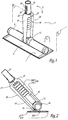
- the device 1 represented at figure 1 includes, in the lower part looking at the figure 1 , a support 2 for a tool, not shown.
- the support 2 has a lower face 3 of generally rectangular shape.
- This surface 3 forms a bearing surface on a surface of a hand tool, not shown, of complementary shape and dimensions. Given the dimensions of the face 3, is easily maintained, preferably removably, a tool.
- This is for example a tool used for finishing coated surfaces, such as a rectangular sanding wedge, to rectangular or triangular cross section.
- the tool can be a sheet of abrasive paper.
- the tool is a lamp.
- Maintaining the wedge or the abrasive sheet on this surface 3 is achieved by known techniques, for example by insertion into slots 4 formed in the sides 5 and 6 of the support 2, as illustrated in FIG. figure 6 .
- the maintenance is provided by self-gripping strips.
- the longitudinal edges 30, 31 of the surface 3 are raised in the direction of the upper surface 7 of the support 2, which allows, when using the device 1 for sanding, to limit the traces between the sanded areas.
- the surface 3 is flat only in its central portion 300. It is slightly curved peripherally, at its edges 30 and 31.
- the support 2 is hollow. As represented in figure 6 spacers 8 connect and stiffen the lower 3 and upper surfaces 7. As a variant not shown, the spacers 8 are pierced or louvered, allowing the communication of the different compartments defined by the spacers. The slots 4 are thus delimited by the spacing between the surfaces 3 and 7.
- a cylindrical body 9, with circular and hollow section, extends, in the median position, from the upper face 7 of the support 2. This cylindrical body 9 is integral with the support 2 so that the longitudinal axes X 9 and X 2 respectively of the body 9 and the support 2 are parallel. The body 9 communicates with the hollow central portion 10 of the support 2. When the spacers 8 are pierced or louvered, all the hollow portions of the body 9 and the support 2 communicate with each other.
- a cutout 11 is formed in the middle part of the cylindrical body 9, that is to say substantially at the center of gravity of the assembly formed by the support 2 and the body 9, a cutout 11 is formed.
- This cut visible at the figure 5 , forms a receiving housing 11 for a ball 12.
- This, visible to Figures 1-4 and 7 is embedded in the cutout 11.
- the ball 12 is in the form of hollow cylinder with circular section.
- the dimensions of the ball 12 are adapted so that it can not be accidentally extracted from the blank 11, while being free in rotation around the longitudinal axis X 9 of the body 9.
- It is provided with a circular relief 13 extending radially with respect to the ball 12.
- the central axis X 13 of the relief 13 is perpendicular to the X axis 9 .
- This relief 13 is provided with an open end 14 open, visible particularly to figures 4 and 7 .
- the relief 13 being hollow, it allows the communication of the inside of the ball 12 with the outside.
- This ball 12 is provided with an opening, not visible in the different figures, formed in the part of the ball 12 which remains permanently inside the cylindrical body 9. It is thus possible to communicate the outside, via the opening 14 of the relief 13 with the interior of the body 9, so with the lower surface 3, to the extent that the latter is provided with at least one hole.
- the ball 12 is also provided with two cups 15, hollowed in the wall of the ball 12, substantially at the bottom 110 of the blank 11, when the support 2 is in the so-called rest position, as illustrated in FIGS. figures 1 and 3 .
- These two cups 15, only one of which is visible at figure 3 are arranged diametrically with respect to each other. They are aligned along an axis X 15 perpendicular to the axis X 13 of the relief 13.
- the cups 15 form receiving housings for lugs, not visible, fixed on the opposite faces of the ends 16, 17 of the teeth 18, respectively 19 of a fork 20 with two teeth.
- the lugs are removably mounted, for example by clipping, in the cups 15 so that they are locked in translation while being rotatable about the X axis 15 .
- the fork 20 is thus rotatable, on the one hand, about an axis X 15 , generally perpendicular to the longitudinal axis X 9 of the body 9 when the device 1 is in the rest configuration, and on the other hand around the X axis 9 , by rotation of the ball 12 in the body 9.
- the fork 20 can pivot about these axes in a limited manner, the limit being reached when the fork 20 is in contact with the cylindrical body 9 when of a rotational movement of the fork 20 around the pivot axis X 15 or in contact with the face 7 of the support 2 during a rotational movement about the axis X 9 .
- This fork 20, illustrated in Figures 1, 2 , 4 and 7 extends, at the portion 21 on which are fixed the teeth 18 and 19, by a tubular member 22 constituting a gripping member of the device 1.
- This part 22 is hollow, cylindrical circular section. According to the invention, the teeth 18, 19 are hollow and also communicate with the part 22.
- the part 22 is provided with two slots 23, configured in a U, arranged diametrically, a slot being visible at the figure 4 .
- the slots 23 each delimit a tongue 24 forming a leaf spring.
- the tongues 24 are provided at their free ends with a relief 25 adapted to ensure, by pressure, a displacement of the tongue 25 directed towards the inside of the tube 22.
- a pin 26 generally circular in shape, is adapted to be inserted into holes of complementary shapes formed in gripping members, not shown.
- Such gripping members are of the female type.
- This is, for example, a hollow end of a handle, a base, or a telescopic handle 30 as illustrated in FIG. figure 8 .
- a free end 31 of the handle 30 is adapted to be connected to at least one type of suction device, for example a tip of a suction pipe.
- the end 31 and the handle 30 are hollow.
- the end 31 is, for example, made of elastomer, with an open portion accordion, with a variable inner diameter.
- the end 31 forms a housing for receiving different tips of suction devices, these end pieces fitting more or less into the end 31 according to their external diameters.
- the tubular end 22 of the fork 20 in a particular gripping member.
- a trajectory F 1 corresponds to rotational movement of the fork 20 about the X axis 15 .
- the other path F 2 corresponds to the pivoting of the ball around the axis X 9 . It should be noted that these movements can be performed simultaneously or not.
- the ball 12 with the cups 15 form a pivot member for pivoting the support 2 relative to the fork 20. The movements are carried out in one direction or the other and in two planes P 1 , P 2 perpendicular.
- a portion 280 of the duct 28 is configured accordion and a portion 281 is cylindrical with circular section . Such a duct 28 is particularly visible at the figure 3 .
- This conduit 28 is open at the ends and, advantageously, made of a flexible material, for example a polymer. It makes it possible to connect the tubular element 22 of the fork 20 and the inside of the ball 12.
- the teeth 18, 19 being hollow, they also connect the tubular element 22 and the inside of the ball 12.
- the accordion portion 280 of the duct 28 allows following the different movements, according to the double arrows F 1 and F 2 , the fork 20, without risking damaging the material constituting the conduit due to the repetition of movements.
- a lamp 29 such as illustrated in figures 7 and 8 .
- a lamp 29 is an LED lamp.
- This lamp can be self-contained, as illustrated in figures 7 and 8 , or connected to the sector. In this case, it is advantageous to pass an electric wire through the orifice 13 of the ball 12 and / or the tubular element 22.
- the ends of the lamp are provided with abutments of damping material, for example rubber stamps.
- the lamp 29 is adapted to be fixed, for example, on a base placed in line with a wall.
- the support 2 equipped with the lamp 29 is mounted, via the tubular element 22, on a telescopic handle 30 of which one end 31 is equipped with a support member, for example a rubber stamp, on a wall 32, in this case the ground.
- the lamp 29 is mounted on a handle forming a strut, horizontal or vertical, for holding the lamp 29 against a surface to be controlled.
- the handle 30 may also be supported, at an angle, on the floor 32, the lamp 29 then bearing against the wall 34.
- the ends of the handle 30 are supported on two parallel walls.
- the support is then provided with a member allowing an operator to slide this support 2, thus the lamp 29, along the handle 30 and to block the support 2 at a given position on the handle 30.
- Such a device makes it possible to access the hard-to-reach parts of the partitions, by acting on the inclination of the support 2 relative to the handle 22 itself.
- the addition of a telescopic handle 30 on the end of the gripping member 22 facilitates the work in the upper part of the partitions.
- the invention also relates to a kit comprising at least one device 1 for holding a hand tool.
- the kit also advantageously comprises at least one other gripping member, for example a telescopic handle provided with a female end adapted to receive and hold, by removable clipping, the gripping member 22.
- the handle is replaced by a base for positioning the device 1 at a given location relative to the surface to be sanded.
- the kit advantageously comprises at least one other tool, for example a set of sanding wedges and / or sanding sheets, knives and scrapers.
- Such a kit allows finishing operations on a surface, previously coated, namely a wall, using the required sanding elements.
Landscapes
- Engineering & Computer Science (AREA)
- Mechanical Engineering (AREA)
- Finish Polishing, Edge Sharpening, And Grinding By Specific Grinding Devices (AREA)
- Dental Tools And Instruments Or Auxiliary Dental Instruments (AREA)
Description
- L'invention a trait à un dispositif de maintien d'un outil à main, notamment d'un outil adapté à la finition d'une surface enduite, ainsi qu'à un kit comprenant un tel dispositif.
- Par outil à main adapté à la finition d'une surface enduite, on désigne ici des outils, ou objets, dont la mise en oeuvre et l'utilisation sont effectuées manuellement par un opérateur dans le cadre de la réalisation des travaux de finition d'une surface enduite, généralement des opérations de ponçage. La surface enduite correspond à une surface, par exemple une paroi, sur laquelle on a projeté, par des techniques connues, un enduit destiné à former une sous-couche avant la mise en place d'un revêtement décoratif, par exemple une peinture ou du papier peint.
- Une fois l'enduit sec, il est nécessaire de poncer la surface afin d'obtenir un état de surface le plus lisse possible. Pour effectuer ce ponçage, outre un matériau abrasif généralement en forme de feuille, on utilise une cale de ponçage, soit plate soit de forme triangulaire, selon la configuration de la surface à poncer. Cette cale permet de maintenir et d'utiliser le matériau abrasif.
- D'autres outils peuvent être également utilisés, par exemple des moyens d'aspiration des poussières générées lors du ponçage et/ou des moyens d'éclairage permettant de contrôler l'efficacité du ponçage en faisant ressortir, par des jeux d'ombre et de lumière, les éventuelles irrégularités de la surface poncée.
- Du fait des dimensions des surfaces à poncer, notamment de la hauteur des parois, et des éventuelles difficultés à accéder aisément aux différents points de ces surfaces, ces travaux de finition nécessitent fréquemment l'utilisation de différents outils et/ou l'emploi de moyens d'élévation, par exemple des escabeaux ou des échafaudages.
-
US-A-2007 141 968 , sur lequel le préambule de la revendication 1 est basé, divulgue un dispositif de ponçage comprenant un organe de préhension, un organe de pivotement et une surface d'appui. La surface d'appui est munie de plusieurs reliefs délimitant entre eux des canaux destinés à assurer l'évacuation des poussières en direction d'un orifice central en communication avec un tube d'évacuation. En raison de la présence de ces reliefs, des traces sont susceptibles d'apparaître entre les zones poncées. - C'est à ces inconvénients qu'entend particulièrement remédier l'invention en proposant un dispositif de maintien d'un outil à main facilitant les travaux de finition des surfaces difficiles d'accès.
- A cet effet, l'invention a pour objet un dispositif de maintien d'un outil à main adapté à la finition d'une surface enduite, ce dispositif étant défini à la revendication 1.
- Le fait de pouvoir faire pivoter dans deux plans perpendiculaires le support de l'outil par rapport à l'organe de préhension facilite, pour l'opérateur, l'accès aux différentes zones de la surface à traiter. La forme de la surface d'appui facilite la mise en oeuvre de l'outil et limite les traces entre les zones poncées.
- Selon des aspects avantageux mais non obligatoires de l'invention, un tel dispositif peut incorporer une ou plusieurs des caractéristiques définies aux revendications 2 à 6.
- L'invention concerne également un kit, comprenant au moins un dispositif de maintien d'un outil à main, tel que défini à la revendication 7.
- L'invention sera mieux comprise et d'autres avantages de celle-ci apparaîtront plus clairement à la lecture de la description qui va suivre de plusieurs modes de réalisation d'un dispositif de maintien d'un outil à main conforme à l'invention, ainsi qu'à un kit comprenant un tel dispositif, donnée uniquement à titre d'exemple et faite en se référant aux dessins annexés dans lesquels :
- la
figure 1 est une vue générale d'un dispositif de maintien d'un outil à main conforme à un mode de réalisation de l'invention, dans une configuration dite de repos, l'organe de préhension n'ayant pas pivoté par rapport au support, le dispositif étant représenté sans outil, - la
figure 2 est une vue de côté à la même échelle, du dispositif de lafigure 1 , dans une configuration dite active, en l'espèce l'organe de préhension étant incliné par rapport au support, - la
figure 3 est une vue similaire à lafigure 1 , sous un autre angle et à la même échelle, une partie du dispositif étant enlevée, - la
figure 4 est une vue de face et à la même échelle, du dispositif représenté auxfigures 1 et 2 , en configuration active, une partie du dispositif étant démontée, - la
figure 5 est une vue générale, à la même échelle, du support de l'outil seul, - la
figure 6 est une coupe, à plus grande échelle, selon le plan VI à lafigure 5 , - la
figure 7 est une vue générale, sous un autre angle, du dispositif représenté à lafigure 4 , avec un outil en position sur le support et - la
figure 8 est une vue générale du dispositif de lafigure 7 , équipé d'un manche, en position d'utilisation, l'outil étant en appui sur une surface. - Le dispositif 1 représenté à la
figure 1 comprend, en partie inférieure en regardant lafigure 1 , un support 2 pour un outil, non illustré. En l'espèce ce support 2 présente une face inférieure 3 de forme globalement rectangulaire. Cette surface 3 forme une surface d'appui à une surface d'un outil à main, non illustré, de forme et de dimensions complémentaires. Compte tenu des dimensions de la face 3, on maintient aisément, avantageusement de manière amovible, un outil. Il s'agit par exemple d'un outil utilisé pour la finition des surfaces enduites, telle qu'une cale de ponçage de forme rectangulaire, à section transversale rectangulaire ou triangulaire. L'outil peut être une feuille de papier abrasif. Dans un mode de réalisation décrit plus loin, l'outil est une lampe. - Le maintien de la cale ou de la feuille abrasive sur cette surface 3 est réalisé par des techniques connues, par exemple par insertion dans des fentes 4 ménagées dans les cotés 5 et 6 du support 2, comme illustré à la
figure 6 . En variante, le maintien est assuré par des bandes auto agrippantes. - Avantageusement, comme illustré à la
figure 6 , les bords longitudinaux 30, 31 de la surface 3 sont relevés en direction de la surface supérieure 7 du support 2, ce qui permet, lorsque l'on se sert du dispositif 1 pour poncer, de limiter les traces entre les zones poncées. De ce fait la surface 3 n'est plane que dans sa partie centrale 300. Elle est légèrement incurvée en périphérie, au niveau de ses bords 30 et 31. - Le support 2 est creux. Comme représenté à la
figure 6 , des entretoises 8 relient et rigidifient les surfaces inférieure 3 et supérieure 7. En variante non illustrée, les entretoises 8 sont percées ou à claire-voie, permettant ainsi la mise en communication des différents compartiments délimités par les entretoises. Les fentes 4 sont ainsi délimitées par l'écartement entre les surfaces 3 et 7. Un corps cylindrique 9, à section circulaire et creux, s'étend, en position médiane, à partir de la face supérieure 7 du support 2. Ce corps cylindrique 9 est venu de matière avec le support 2 de sorte que les axes longitudinaux X9 et X2, respectivement du corps 9 et du support 2 sont parallèles. Le corps 9 communique avec la partie centrale 10 creuse du support 2. Lorsque les entretoises 8 sont percées ou à claire-voie, toutes les parties creuses du corps 9 et du support 2 communiquent entre elles. - En partie médiane du corps cylindrique 9, c'est-à-dire sensiblement au niveau du centre de gravité de l'ensemble formé par le support 2 et le corps 9, une découpe 11 est ménagée. Cette découpe, visible à la
figure 5 , forme un logement 11 de réception pour une rotule 12. Celle-ci, visible auxfigures 1 à 4et 7 , est enchâssée dans la découpe 11. La rotule 12 est en forme de cylindre creux à section circulaire. Les dimensions de la rotule 12, sont adaptées pour qu'elle ne puisse être extraite accidentellement de la découpe 11, tout en étant libre en rotation autour de l'axe longitudinal X9 du corps 9. Elle est pourvue d'un relief circulaire 13 s'étendant radialement par rapport à la rotule 12. Ainsi, l'axe central X13 du relief 13 est perpendiculaire à l'axe X9. Ce relief 13 est pourvu d'une extrémité libre 14 ouverte, visible particulièrement auxfigures 4 et7 . Le relief 13 étant creux, il permet la mise en communication de l'intérieur de la rotule 12 avec l'extérieur. - Cette rotule 12 est pourvue d'une ouverture, non visible aux différentes figures, ménagée dans la partie de la rotule 12 qui reste en permanence à l'intérieur du corps cylindrique 9. Il est ainsi possible de faire communiquer l'extérieur, via l'ouverture 14 du relief 13 avec l'intérieur du corps 9, donc avec la surface inférieure 3, dans la mesure où cette dernière est pourvue d'au moins un perçage.
- La rotule 12 est également pourvue de deux coupelles 15, creusées dans la paroi de la rotule 12, sensiblement au niveau du fond 110 de la découpe 11, lorsque le support 2 est dans la position dite de repos, telle qu'illustrée aux
figures 1 et3 . Ces deux coupelles 15, dont une seule est visible à lafigure 3 , sont disposées diamétralement l'une par rapport à l'autre. Elles sont alignées selon un axe X15 perpendiculaire à l'axe X13 du relief 13. Les coupelles 15 forment des logements de réception pour des ergots, non visibles, fixés sur les faces en regard des extrémités 16, 17 des dents 18, respectivement 19 d'une fourche 20 à deux dents. Les ergots sont montés de manière amovible, par exemple par clipsage, dans les coupelles 15 de sorte qu'ils sont bloqués en translation tout en étant mobiles en rotation autour de l'axe X15. - La fourche 20 est ainsi mobile en rotation, d'une part, autour d'un axe X15, globalement perpendiculaire à l'axe longitudinal X9 du corps 9 lorsque le dispositif 1 est en configuration de repos, et, d'autre part, autour de l'axe X9, par rotation de la rotule 12 dans le corps 9. La fourche 20 peut pivoter autour de ces axes de manière limitée, la limite étant atteinte lorsque la fourche 20 est en contact avec le corps cylindrique 9 lors d'un mouvement de rotation de la fourche 20 autour de l'axe de pivotement X15 ou en contact avec la face 7 du support 2 lors d'un mouvement de rotation autour de l'axe X9.
- Cette fourche 20, illustrée aux
figures 1, 2 ,4 et7 , se prolonge, au niveau de la partie 21 sur laquelle sont fixées les dents 18 et 19, par une pièce tubulaire 22 constitutive d'un organe de préhension du dispositif 1. Cette pièce 22 est creuse, cylindrique à section circulaire. Selon l'invention, les dents 18, 19 sont creuses et communiquent également avec la pièce 22. - La pièce 22 est pourvue de deux fentes 23, configurées en U, disposées diamétralement, une fente étant visible à la
figure 4 . Les fentes 23 délimitent chacune une languette 24 formant un ressort à lame. Les languettes 24 sont pourvues à leurs extrémités libres d'un relief 25 apte à assurer, par pression, un déplacement de la languette 25 dirigé vers l'intérieur du tube 22. Entre ce poussoir 25 et l'extrémité de la languette 24 reliée au tube 22, un pion 26, globalement de forme circulaire, est adapté pour venir s'insérer dans des trous, de formes complémentaires, ménagés dans des organes de préhension, non illustrés. - De tels organes de préhension sont de type femelle. Il s'agit, par exemple, d'une extrémité creuse d'une poignée, d'un socle, ou d'un manche télescopique 30 tel qu'illustré à la
figure 8 . Avantageusement, une extrémité libre 31 du manche 30 est adaptée pour être reliée à au moins un type de dispositif d'aspiration, par exemple un embout d'un tuyau d'aspiration. Pour cela, l'extrémité 31 et le manche 30 sont creux. L'extrémité 31 est, par exemple, réalisée en élastomère, avec une partie ouverte en accordéon, à diamètre intérieur variable. Ainsi l'extrémité 31 forme un logement de réception de différents embouts de dispositifs d'aspiration, ces embouts s'insérant plus ou moins dans l'extrémité 31 selon leurs diamètres externes. Ainsi, on peut insérer de manière amovible, par clipsage, l'extrémité tubulaire 22 de la fourche 20 dans un organe de préhension particulier. - Pour désolidariser la fourche 20, il suffit d'appuyer sur les poussoirs 25 pour que les pions 26, en s'effaçant à l'intérieur du tube 22, se dégagent de leurs logements ménagés dans l'organe de préhension.
- Il est ainsi possible de faire pivoter la fourche 20 par rapport au support 2 selon deux trajectoires, globalement configurées en arc de cercle et illustrées à la
figure 1 par les doubles flèches F1 et F2. Une trajectoire F1 correspond au mouvement de rotation de la fourche 20 autour de l'axe X15. L'autre trajectoire F2 correspond au pivotement de la rotule autour de l'axe X9. Il est à noter que ces mouvements peuvent être réalisés de manière simultanée ou non. En d'autres termes, la rotule 12 avec les coupelles 15 forment un organe de pivotement permettant de faire pivoter le support 2 par rapport à la fourche 20. Les déplacements s'effectuent dans un sens ou dans l'autre et dans deux plans P1, P2 perpendiculaires. - Entre l'ouverture 14 du relief 13 et l'extrémité ouverte 27 de la partie tubulaire 22 de la fourche 20, on dispose un conduit 28. Une partie 280 de ce conduit 28 est configurée en accordéon et une partie 281 est cylindrique à section circulaire. Un tel conduit 28 est particulièrement visible à la
figure 3 . - Ce conduit 28 est ouvert aux extrémités et, avantageusement, fabriqué dans un matériau souple, par exemple un polymère. Il permet de relier l'élément tubulaire 22 de la fourche 20 et l'intérieur de la rotule 12. Les dents 18, 19 étant creuses, elles relient également l'élément tubulaire 22 et l'intérieur de la rotule 12.
- Si l'on connecte l'élément tubulaire 22 à une pompe d'aspiration, il est ainsi possible, via le conduit 28, d'aspirer les poussières récoltées au niveau de la surface 3. La partie 280 en accordéon du conduit 28 permet de suivre les différents mouvements, selon les doubles flèches F1 et F2, de la fourche 20, cela sans risquer d'abîmer le matériau constitutif du conduit du fait de la répétition des mouvements.
- A la place d'un outil de type cale ou feuille de ponçage, il est possible de fixer sur la surface 3, par les mêmes techniques que précédemment ou par d'autres techniques telles que des clips métalliques, une lampe 29, telle qu'illustrée aux
figures 7 et8 . Avantageusement une telle lampe 29 est une lampe à LED. Cette lampe peut être à source autonome, tel qu'illustrée auxfigures 7 et8 , ou reliée au secteur. Dans ce cas on peut avantageusement faire passer un fil électrique par l'orifice 13 de la rotule 12 et/ou l'élément tubulaire 22. En variante non illustrée, les extrémités de la lampe sont pourvues de butées en matériau amortisseur, par exemple des tampons en caoutchouc. - La lampe 29 est adaptée pour être fixée, par exemple, sur un socle posé au droit d'une paroi.
- Dans un mode de réalisation, illustré à la
figure 8 , le support 2 équipé de la lampe 29 est monté, par l'intermédiaire de l'élément tubulaire 22, sur un manche 30 télescopique dont une extrémité 31 est équipée d'un organe d'appui, par exemple un tampon en caoutchouc, sur une paroi 32, en l'espèce le sol. L'appui sur une autre paroi 33, en l'espèce le plafond, parallèle à la paroi 32, d'un bord 290 du support 2 maintenant la lampe 29 permet de bloquer celle-ci en position contre une paroi 34. En d'autres termes, on monte la lampe 29 sur un manche formant un étai, horizontal ou vertical, permettant de maintenir la lampe 29 en appui contre une surface à contrôler. - Le manche 30 peut également être en appui, en biais, sur le sol 32, la lampe 29 étant alors en appui contre la paroi 34.
- Dans un mode de réalisation non illustré, les extrémités du manche 30 sont en appui sur deux parois parallèles. Le support est alors pourvu d'un organe permettant à un opérateur de faire coulisser ce support 2, donc la lampe 29, le long du manche 30 et de bloquer le support 2 en une position donnée sur le manche 30.
- Ainsi, une vérification de l'état de surface après ponçage est effectuée en disposant la lampe 29 de sorte que celle-ci éclaire en lumière rasante la cloison. On réalise ainsi un jeu d'ombres permettant de faire ressortir les éventuelles irrégularités de la surface poncée.
- Il est également possible d'utiliser un tel dispositif sans le conduit tubulaire 28 et/ou sans la fourche 20, c'est-à-dire tel qu'illustré à la
figure 5 . Dans ce cas la forme du corps cylindrique 9 permet à ce dernier de définir un organe de manoeuvre. A lafigure 5 , pour faciliter la lecture du dessin, la rotule 12 n'est pas représentée. Néanmoins, lorsqu'on utilise le dispositif dans cette configuration, la rotule 12 reste en place. En d'autres termes, il est possible à l'utilisateur d'utiliser le support 2 comme une simple cale de maintien d'un outil, avantageusement comme une cale de ponçage munie d'une feuille de matériau abrasif. - Un tel dispositif permet d'accéder aux parties difficilement accessibles des cloisons, en jouant sur l'inclinaison du support 2 par rapport à la poignée 22 proprement dite. L'ajout d'un manche 30 télescopique sur l'extrémité de l'organe de préhension 22 facilite le travail en partie haute des cloisons.
- Il est également aisé de maintenir un angle donné pour des opérations de ponçage en bloquant par des moyens connus en soi l'inclinaison de la rotule 12 et/ou de la fourche 20 à des valeurs données.
- L'invention concerne également un kit comprenant au moins un dispositif 1 de maintien d'un outil à main. Le kit comprend également, de manière avantageuse, au moins un autre organe de préhension, par exemple, un manche 30 télescopique pourvu d'une extrémité femelle adaptée pour recevoir et maintenir, par clipsage amovible, l'organe de préhension 22.
- En variante, le manche est remplacé par un socle permettant de positionner le dispositif 1 à un endroit donné par rapport à la surface à poncer. Le kit comprend avantageusement au moins un autre outil, par exemple un jeu de cales de ponçage et/ou de feuilles de ponçage, des couteaux et grattoirs.
- Un tel kit permet d'effectuer des opérations de finition sur une surface, préalalement enduite, à savoir une paroi, en utilisant les éléments de ponçage requis.
Claims (7)
- Dispositif (1) de maintien d'un outil à main adapté à la finition d'une surface enduite, comportant un support (2) pour l'outil, un organe de préhension (20, 22) et un organe de pivotement (12, 15, 20) adapté pour faire pivoter le support (2) par rapport à l'organe de préhension (22) selon deux trajectoires (F1, F2) situées dans deux plans (P1, P2) perpendiculaires, l'organe de pivotement (12, 15, 20) comprenant :- une rotule (12) montée pivotante autour d'un axe de rotation (X9) parallèle à un axe longitudinal (X2) du support (2), et- une fourche (20) dont les extrémités (16, 17) des dents (18, 19) sont montées pivotantes, sur la rotule (12), autour d'un axe (X15) perpendiculaire à l'axe de rotation (X9) de la rotule (12)le support (2) comprenant au moins une surface d'appui (3) pour une surface complémentaire de l'outil, caractérisé en ce que la surface d'appui (3) du support (2) est plane dans sa partie centrale (300) et incurvée en périphérie (30, 31) et en ce que les dents (18, 19) de la fourche (20) sont creuses et relient l'organe de préhension (22) avec l'intérieur de la rotule (12).
- Dispositif selon la revendication 1, caractérisé en ce que les bords longitudinaux situés en périphérie (30, 31) de la surface d'appui (3) sont relevés en direction d'une surface supérieure (7) du support (2).
- Dispositif selon la revendication 1, caractérisé en ce que l'organe de préhension comprend un élément tubulaire (22) monté sur la partie (21) de la fourche (20) sur laquelle sont fixées les dents (18, 19).
- Dispositif selon la revendication 3, caractérisé en ce que cet élément tubulaire (22) est équipé d'un organe de connexion (24, 25, 26), de manière amovible, à une poignée de manoeuvre, à un socle ou à un manche télescopique (30).
- Dispositif selon la revendication 1, caractérisé en ce que le support (2) est creux et en ce que la surface d'appui (3) est adaptée pour assurer l'aspiration des poussières de ponçage.
- Dispositif selon l'une des revendications précédentes, caractérisé en ce que le support (2) est adapté pour maintenir une lampe (29).
- Kit comprenant au moins un dispositif (1) de maintien d'un outil à main conforme à l'une des revendications précédentes.
Applications Claiming Priority (2)
| Application Number | Priority Date | Filing Date | Title |
|---|---|---|---|
| FR0957686A FR2951984B1 (fr) | 2009-10-30 | 2009-10-30 | Dispositif de maintien d'un outil a main et kit comprenant un tel dispositif |
| PCT/FR2010/052332 WO2011051635A1 (fr) | 2009-10-30 | 2010-10-29 | Dispositif de maintien d'un outil à main et kit comprenant un tel dispositif |
Publications (2)
| Publication Number | Publication Date |
|---|---|
| EP2493661A1 EP2493661A1 (fr) | 2012-09-05 |
| EP2493661B1 true EP2493661B1 (fr) | 2016-12-07 |
Family
ID=42145160
Family Applications (1)
| Application Number | Title | Priority Date | Filing Date |
|---|---|---|---|
| EP10790465.8A Not-in-force EP2493661B1 (fr) | 2009-10-30 | 2010-10-29 | Dispositif de maintien d'un outil à main et kit comprenant un tel dispositif |
Country Status (3)
| Country | Link |
|---|---|
| EP (1) | EP2493661B1 (fr) |
| FR (1) | FR2951984B1 (fr) |
| WO (1) | WO2011051635A1 (fr) |
Cited By (1)
| Publication number | Priority date | Publication date | Assignee | Title |
|---|---|---|---|---|
| CN110206281A (zh) * | 2019-05-09 | 2019-09-06 | 王国华 | 一种建筑工程用喷漆装置 |
Families Citing this family (5)
| Publication number | Priority date | Publication date | Assignee | Title |
|---|---|---|---|---|
| EP2653635A3 (fr) | 2012-04-18 | 2017-08-16 | Scorgim | Equipement et procédé de traitement d'une surface avec un éclairage rasant |
| CA2822631A1 (fr) * | 2013-08-01 | 2015-02-01 | A. Richard Tools Co./Outils A. Richard Co. | Dispositif de poncage et ensemble de poncage le comprenant |
| FR3020389B1 (fr) * | 2014-04-29 | 2016-04-15 | Marquardt | Outil a enduire avec zone de prehension a section circulaire |
| ES3028798T3 (en) * | 2019-10-14 | 2025-06-20 | Edma | Adjustable taping knife handle, and taping knife provided with such a handle |
| FR3101903B1 (fr) * | 2019-10-14 | 2021-11-05 | Grehal Pierre Ets Cie Sa | Poignée de couteau à enduire réglable et couteau à enduire muni d’une telle poignée |
Family Cites Families (7)
| Publication number | Priority date | Publication date | Assignee | Title |
|---|---|---|---|---|
| US3704559A (en) * | 1971-02-11 | 1972-12-05 | Andrew Morgan | Power sander attachment |
| US4204295A (en) * | 1978-10-23 | 1980-05-27 | Connor John D O | Grout scrubber and cleaning tool for tile |
| US4937984A (en) * | 1989-02-23 | 1990-07-03 | Taranto Thomas F | Vacuum sander |
| CA2529354A1 (fr) * | 2005-12-08 | 2007-06-08 | Luigi Panfili | Dispositif de poncage, systeme ainsi equipe, et methode d'utilisation associee |
| DE102006061197A1 (de) * | 2006-12-22 | 2008-06-26 | BSH Bosch und Siemens Hausgeräte GmbH | Bodendüse für Hartböden |
| US7927192B2 (en) * | 2007-10-17 | 2011-04-19 | Full Circle International, Inc | Tool for working on a surface |
| DE202008003385U1 (de) * | 2008-03-06 | 2008-05-15 | Pick, Reinhold | Saugsweeper mit Hohl-Kreuzgelenk |
-
2009
- 2009-10-30 FR FR0957686A patent/FR2951984B1/fr active Active
-
2010
- 2010-10-29 EP EP10790465.8A patent/EP2493661B1/fr not_active Not-in-force
- 2010-10-29 WO PCT/FR2010/052332 patent/WO2011051635A1/fr not_active Ceased
Cited By (1)
| Publication number | Priority date | Publication date | Assignee | Title |
|---|---|---|---|---|
| CN110206281A (zh) * | 2019-05-09 | 2019-09-06 | 王国华 | 一种建筑工程用喷漆装置 |
Also Published As
| Publication number | Publication date |
|---|---|
| EP2493661A1 (fr) | 2012-09-05 |
| FR2951984A1 (fr) | 2011-05-06 |
| FR2951984B1 (fr) | 2012-02-17 |
| WO2011051635A1 (fr) | 2011-05-05 |
Similar Documents
| Publication | Publication Date | Title |
|---|---|---|
| EP2493661A1 (fr) | Dispositif de maintien d'un outil à main et kit comprenant un tel dispositif | |
| FR2966037A3 (fr) | Ensemble balai-eponge | |
| EP3473141B1 (fr) | Support de couteaux avec systeme d affûtage | |
| EP0346177B1 (fr) | Dispositif de fixation d'un tableau ou similaire à l'intérieur d'un cadre | |
| EP3249343B1 (fr) | Module de maintien de canon d'arme a feu et dispositif de support modulaire pour arme a feu comprenant un tel module ainsi qu'un module de maintien de crosse | |
| EP1476287B1 (fr) | Tour de potier comportant un dispositif de guidage pour le formage | |
| WO1997007720A1 (fr) | Organe de support et dispositif de support et de positionnement de tableaux | |
| FR3096706A1 (fr) | Tête d’application pour un applicateur de bande, applicateur de bande muni d’une telle tête | |
| FR3072921B1 (fr) | Support d’appareils multimedia integre dans le dossier de siege de vehicule | |
| EP1800796A1 (fr) | Structure de manutention support de ponceuses girafes | |
| EP3885297B1 (fr) | Dispositif d'application d'une bande de papier | |
| EP3754099B1 (fr) | Dispositif pour le repassage comprenant une planche pourvue d'une surface inclinée | |
| EP3354910A1 (fr) | Agrafe notamment de maintien d'objets tels que des canalisations ou câbles sur une structure de support, par l'intermédiaire d'un organe fileté | |
| EP3320818B1 (fr) | Dispositif de traitement d'aliments muni d'un système de fixation d'un outil | |
| EP3721742A1 (fr) | Parasol a deploiement automatique | |
| FR2814921A3 (fr) | Ensemble a un ou deux verres escamotable dans un etui | |
| EP2573298A1 (fr) | Support de plaque pour appareil destiné à la pose de plaques sur des murs ou plafonds | |
| FR2604940A1 (fr) | Dispositif de maintien pour machine a decouper | |
| EP1637303B1 (fr) | Scie de table, en particulier pour la coupe de carrelages | |
| FR2768073A1 (fr) | Dispositif pour guider controler mesurer et aider l'utilisateur d'une perceuse electrique a main | |
| EP3194179B1 (fr) | Taille-crayon ludique | |
| FR3058350A1 (fr) | Cutter avec une roulette pour controler la pression de coupe | |
| FR2521476A1 (fr) | Dispositif de fixation rapide pour meules abrasives cylindriques, en particulier pour meules plates de satellites ou similaires | |
| FR3053095A1 (fr) | Porte-recipient telescopique | |
| FR3167575A1 (fr) | Ensemble de rangement d’un outil de coupe |
Legal Events
| Date | Code | Title | Description |
|---|---|---|---|
| PUAI | Public reference made under article 153(3) epc to a published international application that has entered the european phase |
Free format text: ORIGINAL CODE: 0009012 |
|
| 17P | Request for examination filed |
Effective date: 20120529 |
|
| AK | Designated contracting states |
Kind code of ref document: A1 Designated state(s): AL AT BE BG CH CY CZ DE DK EE ES FI FR GB GR HR HU IE IS IT LI LT LU LV MC MK MT NL NO PL PT RO RS SE SI SK SM TR |
|
| DAX | Request for extension of the european patent (deleted) | ||
| 17Q | First examination report despatched |
Effective date: 20141029 |
|
| GRAP | Despatch of communication of intention to grant a patent |
Free format text: ORIGINAL CODE: EPIDOSNIGR1 |
|
| INTG | Intention to grant announced |
Effective date: 20160701 |
|
| GRAS | Grant fee paid |
Free format text: ORIGINAL CODE: EPIDOSNIGR3 |
|
| GRAA | (expected) grant |
Free format text: ORIGINAL CODE: 0009210 |
|
| AK | Designated contracting states |
Kind code of ref document: B1 Designated state(s): AL AT BE BG CH CY CZ DE DK EE ES FI FR GB GR HR HU IE IS IT LI LT LU LV MC MK MT NL NO PL PT RO RS SE SI SK SM TR |
|
| REG | Reference to a national code |
Ref country code: GB Ref legal event code: FG4D Free format text: NOT ENGLISH |
|
| REG | Reference to a national code |
Ref country code: CH Ref legal event code: EP Ref country code: AT Ref legal event code: REF Ref document number: 851302 Country of ref document: AT Kind code of ref document: T Effective date: 20161215 |
|
| REG | Reference to a national code |
Ref country code: IE Ref legal event code: FG4D Free format text: LANGUAGE OF EP DOCUMENT: FRENCH |
|
| REG | Reference to a national code |
Ref country code: DE Ref legal event code: R096 Ref document number: 602010038669 Country of ref document: DE |
|
| PG25 | Lapsed in a contracting state [announced via postgrant information from national office to epo] |
Ref country code: LV Free format text: LAPSE BECAUSE OF FAILURE TO SUBMIT A TRANSLATION OF THE DESCRIPTION OR TO PAY THE FEE WITHIN THE PRESCRIBED TIME-LIMIT Effective date: 20161207 |
|
| REG | Reference to a national code |
Ref country code: LT Ref legal event code: MG4D |
|
| REG | Reference to a national code |
Ref country code: NL Ref legal event code: MP Effective date: 20161207 |
|
| PG25 | Lapsed in a contracting state [announced via postgrant information from national office to epo] |
Ref country code: GR Free format text: LAPSE BECAUSE OF FAILURE TO SUBMIT A TRANSLATION OF THE DESCRIPTION OR TO PAY THE FEE WITHIN THE PRESCRIBED TIME-LIMIT Effective date: 20170308 Ref country code: LT Free format text: LAPSE BECAUSE OF FAILURE TO SUBMIT A TRANSLATION OF THE DESCRIPTION OR TO PAY THE FEE WITHIN THE PRESCRIBED TIME-LIMIT Effective date: 20161207 Ref country code: SE Free format text: LAPSE BECAUSE OF FAILURE TO SUBMIT A TRANSLATION OF THE DESCRIPTION OR TO PAY THE FEE WITHIN THE PRESCRIBED TIME-LIMIT Effective date: 20161207 Ref country code: NO Free format text: LAPSE BECAUSE OF FAILURE TO SUBMIT A TRANSLATION OF THE DESCRIPTION OR TO PAY THE FEE WITHIN THE PRESCRIBED TIME-LIMIT Effective date: 20170307 |
|
| REG | Reference to a national code |
Ref country code: AT Ref legal event code: MK05 Ref document number: 851302 Country of ref document: AT Kind code of ref document: T Effective date: 20161207 |
|
| PG25 | Lapsed in a contracting state [announced via postgrant information from national office to epo] |
Ref country code: RS Free format text: LAPSE BECAUSE OF FAILURE TO SUBMIT A TRANSLATION OF THE DESCRIPTION OR TO PAY THE FEE WITHIN THE PRESCRIBED TIME-LIMIT Effective date: 20161207 Ref country code: HR Free format text: LAPSE BECAUSE OF FAILURE TO SUBMIT A TRANSLATION OF THE DESCRIPTION OR TO PAY THE FEE WITHIN THE PRESCRIBED TIME-LIMIT Effective date: 20161207 Ref country code: FI Free format text: LAPSE BECAUSE OF FAILURE TO SUBMIT A TRANSLATION OF THE DESCRIPTION OR TO PAY THE FEE WITHIN THE PRESCRIBED TIME-LIMIT Effective date: 20161207 Ref country code: ES Free format text: LAPSE BECAUSE OF FAILURE TO SUBMIT A TRANSLATION OF THE DESCRIPTION OR TO PAY THE FEE WITHIN THE PRESCRIBED TIME-LIMIT Effective date: 20161207 |
|
| PG25 | Lapsed in a contracting state [announced via postgrant information from national office to epo] |
Ref country code: NL Free format text: LAPSE BECAUSE OF FAILURE TO SUBMIT A TRANSLATION OF THE DESCRIPTION OR TO PAY THE FEE WITHIN THE PRESCRIBED TIME-LIMIT Effective date: 20161207 |
|
| PG25 | Lapsed in a contracting state [announced via postgrant information from national office to epo] |
Ref country code: IS Free format text: LAPSE BECAUSE OF FAILURE TO SUBMIT A TRANSLATION OF THE DESCRIPTION OR TO PAY THE FEE WITHIN THE PRESCRIBED TIME-LIMIT Effective date: 20170407 Ref country code: SK Free format text: LAPSE BECAUSE OF FAILURE TO SUBMIT A TRANSLATION OF THE DESCRIPTION OR TO PAY THE FEE WITHIN THE PRESCRIBED TIME-LIMIT Effective date: 20161207 Ref country code: CZ Free format text: LAPSE BECAUSE OF FAILURE TO SUBMIT A TRANSLATION OF THE DESCRIPTION OR TO PAY THE FEE WITHIN THE PRESCRIBED TIME-LIMIT Effective date: 20161207 Ref country code: EE Free format text: LAPSE BECAUSE OF FAILURE TO SUBMIT A TRANSLATION OF THE DESCRIPTION OR TO PAY THE FEE WITHIN THE PRESCRIBED TIME-LIMIT Effective date: 20161207 Ref country code: RO Free format text: LAPSE BECAUSE OF FAILURE TO SUBMIT A TRANSLATION OF THE DESCRIPTION OR TO PAY THE FEE WITHIN THE PRESCRIBED TIME-LIMIT Effective date: 20161207 |
|
| PG25 | Lapsed in a contracting state [announced via postgrant information from national office to epo] |
Ref country code: PT Free format text: LAPSE BECAUSE OF FAILURE TO SUBMIT A TRANSLATION OF THE DESCRIPTION OR TO PAY THE FEE WITHIN THE PRESCRIBED TIME-LIMIT Effective date: 20170407 Ref country code: AT Free format text: LAPSE BECAUSE OF FAILURE TO SUBMIT A TRANSLATION OF THE DESCRIPTION OR TO PAY THE FEE WITHIN THE PRESCRIBED TIME-LIMIT Effective date: 20161207 Ref country code: IT Free format text: LAPSE BECAUSE OF FAILURE TO SUBMIT A TRANSLATION OF THE DESCRIPTION OR TO PAY THE FEE WITHIN THE PRESCRIBED TIME-LIMIT Effective date: 20161207 Ref country code: PL Free format text: LAPSE BECAUSE OF FAILURE TO SUBMIT A TRANSLATION OF THE DESCRIPTION OR TO PAY THE FEE WITHIN THE PRESCRIBED TIME-LIMIT Effective date: 20161207 Ref country code: SM Free format text: LAPSE BECAUSE OF FAILURE TO SUBMIT A TRANSLATION OF THE DESCRIPTION OR TO PAY THE FEE WITHIN THE PRESCRIBED TIME-LIMIT Effective date: 20161207 Ref country code: BG Free format text: LAPSE BECAUSE OF FAILURE TO SUBMIT A TRANSLATION OF THE DESCRIPTION OR TO PAY THE FEE WITHIN THE PRESCRIBED TIME-LIMIT Effective date: 20170307 |
|
| REG | Reference to a national code |
Ref country code: DE Ref legal event code: R097 Ref document number: 602010038669 Country of ref document: DE |
|
| REG | Reference to a national code |
Ref country code: FR Ref legal event code: PLFP Year of fee payment: 8 |
|
| PLBE | No opposition filed within time limit |
Free format text: ORIGINAL CODE: 0009261 |
|
| STAA | Information on the status of an ep patent application or granted ep patent |
Free format text: STATUS: NO OPPOSITION FILED WITHIN TIME LIMIT |
|
| 26N | No opposition filed |
Effective date: 20170908 |
|
| PG25 | Lapsed in a contracting state [announced via postgrant information from national office to epo] |
Ref country code: DK Free format text: LAPSE BECAUSE OF FAILURE TO SUBMIT A TRANSLATION OF THE DESCRIPTION OR TO PAY THE FEE WITHIN THE PRESCRIBED TIME-LIMIT Effective date: 20161207 Ref country code: SI Free format text: LAPSE BECAUSE OF FAILURE TO SUBMIT A TRANSLATION OF THE DESCRIPTION OR TO PAY THE FEE WITHIN THE PRESCRIBED TIME-LIMIT Effective date: 20161207 |
|
| PG25 | Lapsed in a contracting state [announced via postgrant information from national office to epo] |
Ref country code: MC Free format text: LAPSE BECAUSE OF FAILURE TO SUBMIT A TRANSLATION OF THE DESCRIPTION OR TO PAY THE FEE WITHIN THE PRESCRIBED TIME-LIMIT Effective date: 20161207 |
|
| REG | Reference to a national code |
Ref country code: CH Ref legal event code: PL |
|
| GBPC | Gb: european patent ceased through non-payment of renewal fee |
Effective date: 20171029 |
|
| REG | Reference to a national code |
Ref country code: IE Ref legal event code: MM4A |
|
| PG25 | Lapsed in a contracting state [announced via postgrant information from national office to epo] |
Ref country code: CH Free format text: LAPSE BECAUSE OF NON-PAYMENT OF DUE FEES Effective date: 20171031 Ref country code: LI Free format text: LAPSE BECAUSE OF NON-PAYMENT OF DUE FEES Effective date: 20171031 Ref country code: GB Free format text: LAPSE BECAUSE OF NON-PAYMENT OF DUE FEES Effective date: 20171029 Ref country code: LU Free format text: LAPSE BECAUSE OF NON-PAYMENT OF DUE FEES Effective date: 20171029 |
|
| REG | Reference to a national code |
Ref country code: BE Ref legal event code: MM Effective date: 20171031 |
|
| PG25 | Lapsed in a contracting state [announced via postgrant information from national office to epo] |
Ref country code: BE Free format text: LAPSE BECAUSE OF NON-PAYMENT OF DUE FEES Effective date: 20171031 |
|
| PG25 | Lapsed in a contracting state [announced via postgrant information from national office to epo] |
Ref country code: MT Free format text: LAPSE BECAUSE OF FAILURE TO SUBMIT A TRANSLATION OF THE DESCRIPTION OR TO PAY THE FEE WITHIN THE PRESCRIBED TIME-LIMIT Effective date: 20161207 |
|
| REG | Reference to a national code |
Ref country code: FR Ref legal event code: PLFP Year of fee payment: 9 |
|
| PG25 | Lapsed in a contracting state [announced via postgrant information from national office to epo] |
Ref country code: IE Free format text: LAPSE BECAUSE OF NON-PAYMENT OF DUE FEES Effective date: 20171029 |
|
| PG25 | Lapsed in a contracting state [announced via postgrant information from national office to epo] |
Ref country code: HU Free format text: LAPSE BECAUSE OF FAILURE TO SUBMIT A TRANSLATION OF THE DESCRIPTION OR TO PAY THE FEE WITHIN THE PRESCRIBED TIME-LIMIT; INVALID AB INITIO Effective date: 20101029 |
|
| PG25 | Lapsed in a contracting state [announced via postgrant information from national office to epo] |
Ref country code: CY Free format text: LAPSE BECAUSE OF NON-PAYMENT OF DUE FEES Effective date: 20161207 |
|
| PG25 | Lapsed in a contracting state [announced via postgrant information from national office to epo] |
Ref country code: MK Free format text: LAPSE BECAUSE OF FAILURE TO SUBMIT A TRANSLATION OF THE DESCRIPTION OR TO PAY THE FEE WITHIN THE PRESCRIBED TIME-LIMIT Effective date: 20161207 |
|
| PG25 | Lapsed in a contracting state [announced via postgrant information from national office to epo] |
Ref country code: TR Free format text: LAPSE BECAUSE OF FAILURE TO SUBMIT A TRANSLATION OF THE DESCRIPTION OR TO PAY THE FEE WITHIN THE PRESCRIBED TIME-LIMIT Effective date: 20161207 |
|
| PG25 | Lapsed in a contracting state [announced via postgrant information from national office to epo] |
Ref country code: AL Free format text: LAPSE BECAUSE OF FAILURE TO SUBMIT A TRANSLATION OF THE DESCRIPTION OR TO PAY THE FEE WITHIN THE PRESCRIBED TIME-LIMIT Effective date: 20161207 |
|
| PGFP | Annual fee paid to national office [announced via postgrant information from national office to epo] |
Ref country code: FR Payment date: 20210910 Year of fee payment: 12 |
|
| PGFP | Annual fee paid to national office [announced via postgrant information from national office to epo] |
Ref country code: DE Payment date: 20211008 Year of fee payment: 12 |
|
| REG | Reference to a national code |
Ref country code: DE Ref legal event code: R119 Ref document number: 602010038669 Country of ref document: DE |
|
| PG25 | Lapsed in a contracting state [announced via postgrant information from national office to epo] |
Ref country code: FR Free format text: LAPSE BECAUSE OF NON-PAYMENT OF DUE FEES Effective date: 20221031 Ref country code: DE Free format text: LAPSE BECAUSE OF NON-PAYMENT OF DUE FEES Effective date: 20230503 |