EP2493661B1 - Haltevorrichtung für ein handwerkzeug und kit mit derartiver vorrichtung - Google Patents
Haltevorrichtung für ein handwerkzeug und kit mit derartiver vorrichtung Download PDFInfo
- Publication number
- EP2493661B1 EP2493661B1 EP10790465.8A EP10790465A EP2493661B1 EP 2493661 B1 EP2493661 B1 EP 2493661B1 EP 10790465 A EP10790465 A EP 10790465A EP 2493661 B1 EP2493661 B1 EP 2493661B1
- Authority
- EP
- European Patent Office
- Prior art keywords
- support
- holding
- fork
- pivot
- tool
- Prior art date
- Legal status (The legal status is an assumption and is not a legal conclusion. Google has not performed a legal analysis and makes no representation as to the accuracy of the status listed.)
- Not-in-force
Links
- 230000000295 complement effect Effects 0.000 claims description 3
- 238000005498 polishing Methods 0.000 claims 1
- 238000000034 method Methods 0.000 description 4
- 125000006850 spacer group Chemical group 0.000 description 4
- 210000002105 tongue Anatomy 0.000 description 4
- 239000003082 abrasive agent Substances 0.000 description 3
- 239000011248 coating agent Substances 0.000 description 3
- 238000000576 coating method Methods 0.000 description 3
- 238000004891 communication Methods 0.000 description 3
- 239000000428 dust Substances 0.000 description 3
- 229920001971 elastomer Polymers 0.000 description 3
- 239000000463 material Substances 0.000 description 3
- 238000005192 partition Methods 0.000 description 3
- 230000000903 blocking effect Effects 0.000 description 1
- 238000013016 damping Methods 0.000 description 1
- 238000006073 displacement reaction Methods 0.000 description 1
- 239000000806 elastomer Substances 0.000 description 1
- 238000000605 extraction Methods 0.000 description 1
- 238000005562 fading Methods 0.000 description 1
- 230000005484 gravity Effects 0.000 description 1
- 238000003780 insertion Methods 0.000 description 1
- 230000037431 insertion Effects 0.000 description 1
- 238000012423 maintenance Methods 0.000 description 1
- 239000002184 metal Substances 0.000 description 1
- 239000003973 paint Substances 0.000 description 1
- 238000009304 pastoral farming Methods 0.000 description 1
- 229920000642 polymer Polymers 0.000 description 1
- 230000000284 resting effect Effects 0.000 description 1
- 239000004576 sand Substances 0.000 description 1
- 238000013519 translation Methods 0.000 description 1
Images


Classifications
-
- B—PERFORMING OPERATIONS; TRANSPORTING
- B24—GRINDING; POLISHING
- B24D—TOOLS FOR GRINDING, BUFFING OR SHARPENING
- B24D15/00—Hand tools or other devices for non-rotary grinding, polishing, or stropping
- B24D15/02—Hand tools or other devices for non-rotary grinding, polishing, or stropping rigid; with rigidly-supported operative surface
- B24D15/023—Hand tools or other devices for non-rotary grinding, polishing, or stropping rigid; with rigidly-supported operative surface using in exchangeable arrangement a layer of flexible material
Definitions
- the invention relates to a device for holding a hand tool, in particular a tool suitable for finishing a coated surface, and to a kit comprising such a device.
- tool adapted to the finish of a coated surface means here tools, or objects, the implementation and use are performed manually by an operator in the context of the completion of the finishing work of a coated surface, usually sanding operations.
- the coated surface corresponds to a surface, for example a wall, on which it has been projected, by known techniques, a coating intended to form an underlayer before the introduction of a decorative coating, for example a paint or wallpaper.
- a sanding wedge either flat or triangular, is used depending on the configuration of the surface to be sanded. This wedge makes it possible to maintain and use the abrasive material.
- US-A-2007 141,968 on which the preamble of claim 1 is based, discloses a sanding device comprising a gripping member, a pivot member and a bearing surface.
- the support surface is provided several reliefs delimiting between them channels for ensuring the evacuation of dust towards a central orifice in communication with a discharge tube. Due to the presence of these reliefs, traces are likely to appear between the sanded areas.
- the invention particularly intends to remedy by proposing a device for holding a hand tool facilitating the finishing work of hard to reach surfaces.
- the subject of the invention is a device for holding a hand tool suitable for finishing a coated surface, this device being defined in claim 1.
- the support of the tool relative to the gripping member facilitates, for the operator, access to the different areas of the surface to be treated.
- the shape of the bearing surface facilitates the use of the tool and limits the traces between the sanded areas.
- such a device may incorporate one or more of the features defined in claims 2 to 6.
- the invention also relates to a kit, comprising at least one device for holding a hand tool, as defined in claim 7.
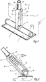
- the device 1 represented at figure 1 includes, in the lower part looking at the figure 1 , a support 2 for a tool, not shown.
- the support 2 has a lower face 3 of generally rectangular shape.
- This surface 3 forms a bearing surface on a surface of a hand tool, not shown, of complementary shape and dimensions. Given the dimensions of the face 3, is easily maintained, preferably removably, a tool.
- This is for example a tool used for finishing coated surfaces, such as a rectangular sanding wedge, to rectangular or triangular cross section.
- the tool can be a sheet of abrasive paper.
- the tool is a lamp.
- Maintaining the wedge or the abrasive sheet on this surface 3 is achieved by known techniques, for example by insertion into slots 4 formed in the sides 5 and 6 of the support 2, as illustrated in FIG. figure 6 .
- the maintenance is provided by self-gripping strips.
- the longitudinal edges 30, 31 of the surface 3 are raised in the direction of the upper surface 7 of the support 2, which allows, when using the device 1 for sanding, to limit the traces between the sanded areas.
- the surface 3 is flat only in its central portion 300. It is slightly curved peripherally, at its edges 30 and 31.
- the support 2 is hollow. As represented in figure 6 spacers 8 connect and stiffen the lower 3 and upper surfaces 7. As a variant not shown, the spacers 8 are pierced or louvered, allowing the communication of the different compartments defined by the spacers. The slots 4 are thus delimited by the spacing between the surfaces 3 and 7.
- a cylindrical body 9, with circular and hollow section, extends, in the median position, from the upper face 7 of the support 2. This cylindrical body 9 is integral with the support 2 so that the longitudinal axes X 9 and X 2 respectively of the body 9 and the support 2 are parallel. The body 9 communicates with the hollow central portion 10 of the support 2. When the spacers 8 are pierced or louvered, all the hollow portions of the body 9 and the support 2 communicate with each other.
- a cutout 11 is formed in the middle part of the cylindrical body 9, that is to say substantially at the center of gravity of the assembly formed by the support 2 and the body 9, a cutout 11 is formed.
- This cut visible at the figure 5 , forms a receiving housing 11 for a ball 12.
- This, visible to Figures 1-4 and 7 is embedded in the cutout 11.
- the ball 12 is in the form of hollow cylinder with circular section.
- the dimensions of the ball 12 are adapted so that it can not be accidentally extracted from the blank 11, while being free in rotation around the longitudinal axis X 9 of the body 9.
- It is provided with a circular relief 13 extending radially with respect to the ball 12.
- the central axis X 13 of the relief 13 is perpendicular to the X axis 9 .
- This relief 13 is provided with an open end 14 open, visible particularly to figures 4 and 7 .
- the relief 13 being hollow, it allows the communication of the inside of the ball 12 with the outside.
- This ball 12 is provided with an opening, not visible in the different figures, formed in the part of the ball 12 which remains permanently inside the cylindrical body 9. It is thus possible to communicate the outside, via the opening 14 of the relief 13 with the interior of the body 9, so with the lower surface 3, to the extent that the latter is provided with at least one hole.
- the ball 12 is also provided with two cups 15, hollowed in the wall of the ball 12, substantially at the bottom 110 of the blank 11, when the support 2 is in the so-called rest position, as illustrated in FIGS. figures 1 and 3 .
- These two cups 15, only one of which is visible at figure 3 are arranged diametrically with respect to each other. They are aligned along an axis X 15 perpendicular to the axis X 13 of the relief 13.
- the cups 15 form receiving housings for lugs, not visible, fixed on the opposite faces of the ends 16, 17 of the teeth 18, respectively 19 of a fork 20 with two teeth.
- the lugs are removably mounted, for example by clipping, in the cups 15 so that they are locked in translation while being rotatable about the X axis 15 .
- the fork 20 is thus rotatable, on the one hand, about an axis X 15 , generally perpendicular to the longitudinal axis X 9 of the body 9 when the device 1 is in the rest configuration, and on the other hand around the X axis 9 , by rotation of the ball 12 in the body 9.
- the fork 20 can pivot about these axes in a limited manner, the limit being reached when the fork 20 is in contact with the cylindrical body 9 when of a rotational movement of the fork 20 around the pivot axis X 15 or in contact with the face 7 of the support 2 during a rotational movement about the axis X 9 .
- This fork 20, illustrated in Figures 1, 2 , 4 and 7 extends, at the portion 21 on which are fixed the teeth 18 and 19, by a tubular member 22 constituting a gripping member of the device 1.
- This part 22 is hollow, cylindrical circular section. According to the invention, the teeth 18, 19 are hollow and also communicate with the part 22.
- the part 22 is provided with two slots 23, configured in a U, arranged diametrically, a slot being visible at the figure 4 .
- the slots 23 each delimit a tongue 24 forming a leaf spring.
- the tongues 24 are provided at their free ends with a relief 25 adapted to ensure, by pressure, a displacement of the tongue 25 directed towards the inside of the tube 22.
- a pin 26 generally circular in shape, is adapted to be inserted into holes of complementary shapes formed in gripping members, not shown.
- Such gripping members are of the female type.
- This is, for example, a hollow end of a handle, a base, or a telescopic handle 30 as illustrated in FIG. figure 8 .
- a free end 31 of the handle 30 is adapted to be connected to at least one type of suction device, for example a tip of a suction pipe.
- the end 31 and the handle 30 are hollow.
- the end 31 is, for example, made of elastomer, with an open portion accordion, with a variable inner diameter.
- the end 31 forms a housing for receiving different tips of suction devices, these end pieces fitting more or less into the end 31 according to their external diameters.
- the tubular end 22 of the fork 20 in a particular gripping member.
- a trajectory F 1 corresponds to rotational movement of the fork 20 about the X axis 15 .
- the other path F 2 corresponds to the pivoting of the ball around the axis X 9 . It should be noted that these movements can be performed simultaneously or not.
- the ball 12 with the cups 15 form a pivot member for pivoting the support 2 relative to the fork 20. The movements are carried out in one direction or the other and in two planes P 1 , P 2 perpendicular.
- a portion 280 of the duct 28 is configured accordion and a portion 281 is cylindrical with circular section . Such a duct 28 is particularly visible at the figure 3 .
- This conduit 28 is open at the ends and, advantageously, made of a flexible material, for example a polymer. It makes it possible to connect the tubular element 22 of the fork 20 and the inside of the ball 12.
- the teeth 18, 19 being hollow, they also connect the tubular element 22 and the inside of the ball 12.
- the accordion portion 280 of the duct 28 allows following the different movements, according to the double arrows F 1 and F 2 , the fork 20, without risking damaging the material constituting the conduit due to the repetition of movements.
- a lamp 29 such as illustrated in figures 7 and 8 .
- a lamp 29 is an LED lamp.
- This lamp can be self-contained, as illustrated in figures 7 and 8 , or connected to the sector. In this case, it is advantageous to pass an electric wire through the orifice 13 of the ball 12 and / or the tubular element 22.
- the ends of the lamp are provided with abutments of damping material, for example rubber stamps.
- the lamp 29 is adapted to be fixed, for example, on a base placed in line with a wall.
- the support 2 equipped with the lamp 29 is mounted, via the tubular element 22, on a telescopic handle 30 of which one end 31 is equipped with a support member, for example a rubber stamp, on a wall 32, in this case the ground.
- the lamp 29 is mounted on a handle forming a strut, horizontal or vertical, for holding the lamp 29 against a surface to be controlled.
- the handle 30 may also be supported, at an angle, on the floor 32, the lamp 29 then bearing against the wall 34.
- the ends of the handle 30 are supported on two parallel walls.
- the support is then provided with a member allowing an operator to slide this support 2, thus the lamp 29, along the handle 30 and to block the support 2 at a given position on the handle 30.
- Such a device makes it possible to access the hard-to-reach parts of the partitions, by acting on the inclination of the support 2 relative to the handle 22 itself.
- the addition of a telescopic handle 30 on the end of the gripping member 22 facilitates the work in the upper part of the partitions.
- the invention also relates to a kit comprising at least one device 1 for holding a hand tool.
- the kit also advantageously comprises at least one other gripping member, for example a telescopic handle provided with a female end adapted to receive and hold, by removable clipping, the gripping member 22.
- the handle is replaced by a base for positioning the device 1 at a given location relative to the surface to be sanded.
- the kit advantageously comprises at least one other tool, for example a set of sanding wedges and / or sanding sheets, knives and scrapers.
- Such a kit allows finishing operations on a surface, previously coated, namely a wall, using the required sanding elements.
Landscapes
- Engineering & Computer Science (AREA)
- Mechanical Engineering (AREA)
- Finish Polishing, Edge Sharpening, And Grinding By Specific Grinding Devices (AREA)
- Dental Tools And Instruments Or Auxiliary Dental Instruments (AREA)
Claims (7)
- Vorrichtung (1) zum Halten eines Handwerkzeugs, das für die Endbearbeitung einer beschichteten Oberfläche geeignet ist, umfassend einen Träger (2) für das Werkzeug, ein Greifelement (20, 22) und ein Schwenkelement (12, 15, 20), das ausgebildet ist, den Träger (2) in Bezug auf das Greifelement (22) gemäß zweier in zwei senkrechten Ebenen (P1, P2) gelegenen Bahnen (F1, F2) zu schwenken, wobei das Schwenkelement (12, 15, 20) umfasst:- ein Kugelgelenk (12), das schwenkbar um eine Drehachse (X9) parallel zu einer Längsachse (X2) des Trägers (2) montiert ist, und- eine Gabel (20), deren Enden (16, 17) der Zinken (18, 19) schwenkbar an dem Kugelgelenk (12) um eine Achse (X15) senkrecht zur Drehachse (X9) des Kugelgelenks (12) montiert sind,wobei der Träger (2) mindestens eine Auflagefläche (3) für eine komplementäre Fläche des Werkzeugs umfasst, dadurch gekennzeichnet, dass die Auflagefläche (3) des Trägers (2) in ihrem Mittelbereich (300) eben und am Umfang (30, 31) gekrümmt ist und dass die Zinken (18, 19) der Gabel (20) hohl sind und das Greifelement (22) mit dem Inneren des Kugelgelenks (12) verbinden.
- Vorrichtung nach Anspruch 1, dadurch gekennzeichnet, dass die am Umfang der Auflagefläche (3) liegenden Längsränder (30, 31) in Richtung einer Fläche (7) über dem Träger (2) angehoben sind.
- Vorrichtung nach Anspruch 1, dadurch gekennzeichnet, dass das Greifelement ein rohrförmiges Element (22) umfasst, das an dem Bereich (21) der Gabel (20) montiert ist, an dem die Zinken (18, 19) befestigt sind.
- Vorrichtung nach Anspruch 3, dadurch gekennzeichnet, dass dieses rohrförmige Element (22) mit einem Verbindungselement (24, 25, 26) ausgestattet ist, das in lösbarer Weise an einem Betätigungsgriff, an einem Sockel oder an einem Teleskoparm (30) angeordnet ist.
- Vorrichtung nach Anspruch 1, dadurch gekennzeichnet, dass der Träger (2) hohl ist und dass die Auflagefläche (3) ausgebildet ist, das Ansaugen von Schleifstaub sicherzustellen.
- Vorrichtung nach einem der vorhergehendenden Ansprüche, dadurch gekennzeichnet, dass der Träger (2) ausgebildet ist, eine Lampe (29) zu halten.
- Bausatz, mindestens eine Vorrichtung (1) zum Halten eines Handwerkzeugs nach einem der vorhergehenden Ansprüche umfassend.
Applications Claiming Priority (2)
| Application Number | Priority Date | Filing Date | Title |
|---|---|---|---|
| FR0957686A FR2951984B1 (fr) | 2009-10-30 | 2009-10-30 | Dispositif de maintien d'un outil a main et kit comprenant un tel dispositif |
| PCT/FR2010/052332 WO2011051635A1 (fr) | 2009-10-30 | 2010-10-29 | Dispositif de maintien d'un outil à main et kit comprenant un tel dispositif |
Publications (2)
| Publication Number | Publication Date |
|---|---|
| EP2493661A1 EP2493661A1 (de) | 2012-09-05 |
| EP2493661B1 true EP2493661B1 (de) | 2016-12-07 |
Family
ID=42145160
Family Applications (1)
| Application Number | Title | Priority Date | Filing Date |
|---|---|---|---|
| EP10790465.8A Not-in-force EP2493661B1 (de) | 2009-10-30 | 2010-10-29 | Haltevorrichtung für ein handwerkzeug und kit mit derartiver vorrichtung |
Country Status (3)
| Country | Link |
|---|---|
| EP (1) | EP2493661B1 (de) |
| FR (1) | FR2951984B1 (de) |
| WO (1) | WO2011051635A1 (de) |
Cited By (1)
| Publication number | Priority date | Publication date | Assignee | Title |
|---|---|---|---|---|
| CN110206281A (zh) * | 2019-05-09 | 2019-09-06 | 王国华 | 一种建筑工程用喷漆装置 |
Families Citing this family (5)
| Publication number | Priority date | Publication date | Assignee | Title |
|---|---|---|---|---|
| EP2653635A3 (de) | 2012-04-18 | 2017-08-16 | Scorgim | Ausrüstung und Verfahren zur Behandlung einer Oberfläche mit Streiflicht |
| CA2822631A1 (en) * | 2013-08-01 | 2015-02-01 | A. Richard Tools Co./Outils A. Richard Co. | Sanding device, and sanding assembly including the same |
| FR3020389B1 (fr) * | 2014-04-29 | 2016-04-15 | Marquardt | Outil a enduire avec zone de prehension a section circulaire |
| ES3028798T3 (en) * | 2019-10-14 | 2025-06-20 | Edma | Adjustable taping knife handle, and taping knife provided with such a handle |
| FR3101903B1 (fr) * | 2019-10-14 | 2021-11-05 | Grehal Pierre Ets Cie Sa | Poignée de couteau à enduire réglable et couteau à enduire muni d’une telle poignée |
Family Cites Families (7)
| Publication number | Priority date | Publication date | Assignee | Title |
|---|---|---|---|---|
| US3704559A (en) * | 1971-02-11 | 1972-12-05 | Andrew Morgan | Power sander attachment |
| US4204295A (en) * | 1978-10-23 | 1980-05-27 | Connor John D O | Grout scrubber and cleaning tool for tile |
| US4937984A (en) * | 1989-02-23 | 1990-07-03 | Taranto Thomas F | Vacuum sander |
| CA2529354A1 (en) * | 2005-12-08 | 2007-06-08 | Luigi Panfili | Sanding device, system including the same, and method of operating associated thereto |
| DE102006061197A1 (de) * | 2006-12-22 | 2008-06-26 | BSH Bosch und Siemens Hausgeräte GmbH | Bodendüse für Hartböden |
| US7927192B2 (en) * | 2007-10-17 | 2011-04-19 | Full Circle International, Inc | Tool for working on a surface |
| DE202008003385U1 (de) * | 2008-03-06 | 2008-05-15 | Pick, Reinhold | Saugsweeper mit Hohl-Kreuzgelenk |
-
2009
- 2009-10-30 FR FR0957686A patent/FR2951984B1/fr active Active
-
2010
- 2010-10-29 EP EP10790465.8A patent/EP2493661B1/de not_active Not-in-force
- 2010-10-29 WO PCT/FR2010/052332 patent/WO2011051635A1/fr not_active Ceased
Cited By (1)
| Publication number | Priority date | Publication date | Assignee | Title |
|---|---|---|---|---|
| CN110206281A (zh) * | 2019-05-09 | 2019-09-06 | 王国华 | 一种建筑工程用喷漆装置 |
Also Published As
| Publication number | Publication date |
|---|---|
| EP2493661A1 (de) | 2012-09-05 |
| FR2951984A1 (fr) | 2011-05-06 |
| FR2951984B1 (fr) | 2012-02-17 |
| WO2011051635A1 (fr) | 2011-05-05 |
Similar Documents
| Publication | Publication Date | Title |
|---|---|---|
| EP2493661A1 (de) | Haltevorrichtung für ein handwerkzeug und kit mit derartiver vorrichtung | |
| FR2966037A3 (fr) | Ensemble balai-eponge | |
| EP3473141B1 (de) | Messerhalterung mit schleifsystem | |
| EP0346177B1 (de) | Befestigungsvorrichtung für eine Platte oder ähnliches im inneren eines Rahmens | |
| EP3249343B1 (de) | Haltemodul für den lauf einer feuerwaffe, und modulare halterungsvorrichtung für feuerwaffe, die ein solches modul sowie ein haltemodul für den griff umfasst | |
| EP1476287B1 (de) | Töpferscheibe mit einer führungseinrichtung zur formung | |
| WO1997007720A1 (fr) | Organe de support et dispositif de support et de positionnement de tableaux | |
| FR3096706A1 (fr) | Tête d’application pour un applicateur de bande, applicateur de bande muni d’une telle tête | |
| FR3072921B1 (fr) | Support d’appareils multimedia integre dans le dossier de siege de vehicule | |
| EP1800796A1 (de) | Tragkonstruktion für eine Stabpoliermaschine | |
| EP3885297B1 (de) | Vorrichtung zum aufbringen eines papierstreifens | |
| EP3754099B1 (de) | Bügelvorrichtung mit einem bügelbrett mit geneigter oberfläche | |
| EP3354910A1 (de) | Klammer, insbesondere zur halterung von gegenständen, wie etwa rohrleitungen oder kabeln, auf einer halterungsstruktur mithilfe eines gewindeorgans | |
| EP3320818B1 (de) | Vorrichtung zur behandlung von lebensmitteln, die mit einem befestigungssystem für ein werkzeug ausgestattet ist | |
| EP3721742A1 (de) | Automatisch aufklappender sonnenschirm | |
| FR2814921A3 (fr) | Ensemble a un ou deux verres escamotable dans un etui | |
| EP2573298A1 (de) | Plattenhalterung für eine Vorrichtung zum Montieren von Platten an Wänden oder Decken | |
| FR2604940A1 (fr) | Dispositif de maintien pour machine a decouper | |
| EP1637303B1 (de) | Tischsäge, insbesondere zum Schneiden von Fliesen | |
| FR2768073A1 (fr) | Dispositif pour guider controler mesurer et aider l'utilisateur d'une perceuse electrique a main | |
| EP3194179B1 (de) | Spielbleistiftspitzer | |
| FR3058350A1 (fr) | Cutter avec une roulette pour controler la pression de coupe | |
| FR2521476A1 (fr) | Dispositif de fixation rapide pour meules abrasives cylindriques, en particulier pour meules plates de satellites ou similaires | |
| FR3053095A1 (fr) | Porte-recipient telescopique | |
| FR3167575A1 (fr) | Ensemble de rangement d’un outil de coupe |
Legal Events
| Date | Code | Title | Description |
|---|---|---|---|
| PUAI | Public reference made under article 153(3) epc to a published international application that has entered the european phase |
Free format text: ORIGINAL CODE: 0009012 |
|
| 17P | Request for examination filed |
Effective date: 20120529 |
|
| AK | Designated contracting states |
Kind code of ref document: A1 Designated state(s): AL AT BE BG CH CY CZ DE DK EE ES FI FR GB GR HR HU IE IS IT LI LT LU LV MC MK MT NL NO PL PT RO RS SE SI SK SM TR |
|
| DAX | Request for extension of the european patent (deleted) | ||
| 17Q | First examination report despatched |
Effective date: 20141029 |
|
| GRAP | Despatch of communication of intention to grant a patent |
Free format text: ORIGINAL CODE: EPIDOSNIGR1 |
|
| INTG | Intention to grant announced |
Effective date: 20160701 |
|
| GRAS | Grant fee paid |
Free format text: ORIGINAL CODE: EPIDOSNIGR3 |
|
| GRAA | (expected) grant |
Free format text: ORIGINAL CODE: 0009210 |
|
| AK | Designated contracting states |
Kind code of ref document: B1 Designated state(s): AL AT BE BG CH CY CZ DE DK EE ES FI FR GB GR HR HU IE IS IT LI LT LU LV MC MK MT NL NO PL PT RO RS SE SI SK SM TR |
|
| REG | Reference to a national code |
Ref country code: GB Ref legal event code: FG4D Free format text: NOT ENGLISH |
|
| REG | Reference to a national code |
Ref country code: CH Ref legal event code: EP Ref country code: AT Ref legal event code: REF Ref document number: 851302 Country of ref document: AT Kind code of ref document: T Effective date: 20161215 |
|
| REG | Reference to a national code |
Ref country code: IE Ref legal event code: FG4D Free format text: LANGUAGE OF EP DOCUMENT: FRENCH |
|
| REG | Reference to a national code |
Ref country code: DE Ref legal event code: R096 Ref document number: 602010038669 Country of ref document: DE |
|
| PG25 | Lapsed in a contracting state [announced via postgrant information from national office to epo] |
Ref country code: LV Free format text: LAPSE BECAUSE OF FAILURE TO SUBMIT A TRANSLATION OF THE DESCRIPTION OR TO PAY THE FEE WITHIN THE PRESCRIBED TIME-LIMIT Effective date: 20161207 |
|
| REG | Reference to a national code |
Ref country code: LT Ref legal event code: MG4D |
|
| REG | Reference to a national code |
Ref country code: NL Ref legal event code: MP Effective date: 20161207 |
|
| PG25 | Lapsed in a contracting state [announced via postgrant information from national office to epo] |
Ref country code: GR Free format text: LAPSE BECAUSE OF FAILURE TO SUBMIT A TRANSLATION OF THE DESCRIPTION OR TO PAY THE FEE WITHIN THE PRESCRIBED TIME-LIMIT Effective date: 20170308 Ref country code: LT Free format text: LAPSE BECAUSE OF FAILURE TO SUBMIT A TRANSLATION OF THE DESCRIPTION OR TO PAY THE FEE WITHIN THE PRESCRIBED TIME-LIMIT Effective date: 20161207 Ref country code: SE Free format text: LAPSE BECAUSE OF FAILURE TO SUBMIT A TRANSLATION OF THE DESCRIPTION OR TO PAY THE FEE WITHIN THE PRESCRIBED TIME-LIMIT Effective date: 20161207 Ref country code: NO Free format text: LAPSE BECAUSE OF FAILURE TO SUBMIT A TRANSLATION OF THE DESCRIPTION OR TO PAY THE FEE WITHIN THE PRESCRIBED TIME-LIMIT Effective date: 20170307 |
|
| REG | Reference to a national code |
Ref country code: AT Ref legal event code: MK05 Ref document number: 851302 Country of ref document: AT Kind code of ref document: T Effective date: 20161207 |
|
| PG25 | Lapsed in a contracting state [announced via postgrant information from national office to epo] |
Ref country code: RS Free format text: LAPSE BECAUSE OF FAILURE TO SUBMIT A TRANSLATION OF THE DESCRIPTION OR TO PAY THE FEE WITHIN THE PRESCRIBED TIME-LIMIT Effective date: 20161207 Ref country code: HR Free format text: LAPSE BECAUSE OF FAILURE TO SUBMIT A TRANSLATION OF THE DESCRIPTION OR TO PAY THE FEE WITHIN THE PRESCRIBED TIME-LIMIT Effective date: 20161207 Ref country code: FI Free format text: LAPSE BECAUSE OF FAILURE TO SUBMIT A TRANSLATION OF THE DESCRIPTION OR TO PAY THE FEE WITHIN THE PRESCRIBED TIME-LIMIT Effective date: 20161207 Ref country code: ES Free format text: LAPSE BECAUSE OF FAILURE TO SUBMIT A TRANSLATION OF THE DESCRIPTION OR TO PAY THE FEE WITHIN THE PRESCRIBED TIME-LIMIT Effective date: 20161207 |
|
| PG25 | Lapsed in a contracting state [announced via postgrant information from national office to epo] |
Ref country code: NL Free format text: LAPSE BECAUSE OF FAILURE TO SUBMIT A TRANSLATION OF THE DESCRIPTION OR TO PAY THE FEE WITHIN THE PRESCRIBED TIME-LIMIT Effective date: 20161207 |
|
| PG25 | Lapsed in a contracting state [announced via postgrant information from national office to epo] |
Ref country code: IS Free format text: LAPSE BECAUSE OF FAILURE TO SUBMIT A TRANSLATION OF THE DESCRIPTION OR TO PAY THE FEE WITHIN THE PRESCRIBED TIME-LIMIT Effective date: 20170407 Ref country code: SK Free format text: LAPSE BECAUSE OF FAILURE TO SUBMIT A TRANSLATION OF THE DESCRIPTION OR TO PAY THE FEE WITHIN THE PRESCRIBED TIME-LIMIT Effective date: 20161207 Ref country code: CZ Free format text: LAPSE BECAUSE OF FAILURE TO SUBMIT A TRANSLATION OF THE DESCRIPTION OR TO PAY THE FEE WITHIN THE PRESCRIBED TIME-LIMIT Effective date: 20161207 Ref country code: EE Free format text: LAPSE BECAUSE OF FAILURE TO SUBMIT A TRANSLATION OF THE DESCRIPTION OR TO PAY THE FEE WITHIN THE PRESCRIBED TIME-LIMIT Effective date: 20161207 Ref country code: RO Free format text: LAPSE BECAUSE OF FAILURE TO SUBMIT A TRANSLATION OF THE DESCRIPTION OR TO PAY THE FEE WITHIN THE PRESCRIBED TIME-LIMIT Effective date: 20161207 |
|
| PG25 | Lapsed in a contracting state [announced via postgrant information from national office to epo] |
Ref country code: PT Free format text: LAPSE BECAUSE OF FAILURE TO SUBMIT A TRANSLATION OF THE DESCRIPTION OR TO PAY THE FEE WITHIN THE PRESCRIBED TIME-LIMIT Effective date: 20170407 Ref country code: AT Free format text: LAPSE BECAUSE OF FAILURE TO SUBMIT A TRANSLATION OF THE DESCRIPTION OR TO PAY THE FEE WITHIN THE PRESCRIBED TIME-LIMIT Effective date: 20161207 Ref country code: IT Free format text: LAPSE BECAUSE OF FAILURE TO SUBMIT A TRANSLATION OF THE DESCRIPTION OR TO PAY THE FEE WITHIN THE PRESCRIBED TIME-LIMIT Effective date: 20161207 Ref country code: PL Free format text: LAPSE BECAUSE OF FAILURE TO SUBMIT A TRANSLATION OF THE DESCRIPTION OR TO PAY THE FEE WITHIN THE PRESCRIBED TIME-LIMIT Effective date: 20161207 Ref country code: SM Free format text: LAPSE BECAUSE OF FAILURE TO SUBMIT A TRANSLATION OF THE DESCRIPTION OR TO PAY THE FEE WITHIN THE PRESCRIBED TIME-LIMIT Effective date: 20161207 Ref country code: BG Free format text: LAPSE BECAUSE OF FAILURE TO SUBMIT A TRANSLATION OF THE DESCRIPTION OR TO PAY THE FEE WITHIN THE PRESCRIBED TIME-LIMIT Effective date: 20170307 |
|
| REG | Reference to a national code |
Ref country code: DE Ref legal event code: R097 Ref document number: 602010038669 Country of ref document: DE |
|
| REG | Reference to a national code |
Ref country code: FR Ref legal event code: PLFP Year of fee payment: 8 |
|
| PLBE | No opposition filed within time limit |
Free format text: ORIGINAL CODE: 0009261 |
|
| STAA | Information on the status of an ep patent application or granted ep patent |
Free format text: STATUS: NO OPPOSITION FILED WITHIN TIME LIMIT |
|
| 26N | No opposition filed |
Effective date: 20170908 |
|
| PG25 | Lapsed in a contracting state [announced via postgrant information from national office to epo] |
Ref country code: DK Free format text: LAPSE BECAUSE OF FAILURE TO SUBMIT A TRANSLATION OF THE DESCRIPTION OR TO PAY THE FEE WITHIN THE PRESCRIBED TIME-LIMIT Effective date: 20161207 Ref country code: SI Free format text: LAPSE BECAUSE OF FAILURE TO SUBMIT A TRANSLATION OF THE DESCRIPTION OR TO PAY THE FEE WITHIN THE PRESCRIBED TIME-LIMIT Effective date: 20161207 |
|
| PG25 | Lapsed in a contracting state [announced via postgrant information from national office to epo] |
Ref country code: MC Free format text: LAPSE BECAUSE OF FAILURE TO SUBMIT A TRANSLATION OF THE DESCRIPTION OR TO PAY THE FEE WITHIN THE PRESCRIBED TIME-LIMIT Effective date: 20161207 |
|
| REG | Reference to a national code |
Ref country code: CH Ref legal event code: PL |
|
| GBPC | Gb: european patent ceased through non-payment of renewal fee |
Effective date: 20171029 |
|
| REG | Reference to a national code |
Ref country code: IE Ref legal event code: MM4A |
|
| PG25 | Lapsed in a contracting state [announced via postgrant information from national office to epo] |
Ref country code: CH Free format text: LAPSE BECAUSE OF NON-PAYMENT OF DUE FEES Effective date: 20171031 Ref country code: LI Free format text: LAPSE BECAUSE OF NON-PAYMENT OF DUE FEES Effective date: 20171031 Ref country code: GB Free format text: LAPSE BECAUSE OF NON-PAYMENT OF DUE FEES Effective date: 20171029 Ref country code: LU Free format text: LAPSE BECAUSE OF NON-PAYMENT OF DUE FEES Effective date: 20171029 |
|
| REG | Reference to a national code |
Ref country code: BE Ref legal event code: MM Effective date: 20171031 |
|
| PG25 | Lapsed in a contracting state [announced via postgrant information from national office to epo] |
Ref country code: BE Free format text: LAPSE BECAUSE OF NON-PAYMENT OF DUE FEES Effective date: 20171031 |
|
| PG25 | Lapsed in a contracting state [announced via postgrant information from national office to epo] |
Ref country code: MT Free format text: LAPSE BECAUSE OF FAILURE TO SUBMIT A TRANSLATION OF THE DESCRIPTION OR TO PAY THE FEE WITHIN THE PRESCRIBED TIME-LIMIT Effective date: 20161207 |
|
| REG | Reference to a national code |
Ref country code: FR Ref legal event code: PLFP Year of fee payment: 9 |
|
| PG25 | Lapsed in a contracting state [announced via postgrant information from national office to epo] |
Ref country code: IE Free format text: LAPSE BECAUSE OF NON-PAYMENT OF DUE FEES Effective date: 20171029 |
|
| PG25 | Lapsed in a contracting state [announced via postgrant information from national office to epo] |
Ref country code: HU Free format text: LAPSE BECAUSE OF FAILURE TO SUBMIT A TRANSLATION OF THE DESCRIPTION OR TO PAY THE FEE WITHIN THE PRESCRIBED TIME-LIMIT; INVALID AB INITIO Effective date: 20101029 |
|
| PG25 | Lapsed in a contracting state [announced via postgrant information from national office to epo] |
Ref country code: CY Free format text: LAPSE BECAUSE OF NON-PAYMENT OF DUE FEES Effective date: 20161207 |
|
| PG25 | Lapsed in a contracting state [announced via postgrant information from national office to epo] |
Ref country code: MK Free format text: LAPSE BECAUSE OF FAILURE TO SUBMIT A TRANSLATION OF THE DESCRIPTION OR TO PAY THE FEE WITHIN THE PRESCRIBED TIME-LIMIT Effective date: 20161207 |
|
| PG25 | Lapsed in a contracting state [announced via postgrant information from national office to epo] |
Ref country code: TR Free format text: LAPSE BECAUSE OF FAILURE TO SUBMIT A TRANSLATION OF THE DESCRIPTION OR TO PAY THE FEE WITHIN THE PRESCRIBED TIME-LIMIT Effective date: 20161207 |
|
| PG25 | Lapsed in a contracting state [announced via postgrant information from national office to epo] |
Ref country code: AL Free format text: LAPSE BECAUSE OF FAILURE TO SUBMIT A TRANSLATION OF THE DESCRIPTION OR TO PAY THE FEE WITHIN THE PRESCRIBED TIME-LIMIT Effective date: 20161207 |
|
| PGFP | Annual fee paid to national office [announced via postgrant information from national office to epo] |
Ref country code: FR Payment date: 20210910 Year of fee payment: 12 |
|
| PGFP | Annual fee paid to national office [announced via postgrant information from national office to epo] |
Ref country code: DE Payment date: 20211008 Year of fee payment: 12 |
|
| REG | Reference to a national code |
Ref country code: DE Ref legal event code: R119 Ref document number: 602010038669 Country of ref document: DE |
|
| PG25 | Lapsed in a contracting state [announced via postgrant information from national office to epo] |
Ref country code: FR Free format text: LAPSE BECAUSE OF NON-PAYMENT OF DUE FEES Effective date: 20221031 Ref country code: DE Free format text: LAPSE BECAUSE OF NON-PAYMENT OF DUE FEES Effective date: 20230503 |