EP2493797B1 - Appareil d'alimentation de matériaux avec liaison pour organe de serrage - Google Patents
Appareil d'alimentation de matériaux avec liaison pour organe de serrage Download PDFInfo
- Publication number
- EP2493797B1 EP2493797B1 EP10827603.1A EP10827603A EP2493797B1 EP 2493797 B1 EP2493797 B1 EP 2493797B1 EP 10827603 A EP10827603 A EP 10827603A EP 2493797 B1 EP2493797 B1 EP 2493797B1
- Authority
- EP
- European Patent Office
- Prior art keywords
- gripper mechanism
- gripping member
- workpiece
- gripping
- actuator
- Prior art date
- Legal status (The legal status is an assumption and is not a legal conclusion. Google has not performed a legal analysis and makes no representation as to the accuracy of the status listed.)
- Active
Links
- 239000000463 material Substances 0.000 title description 16
- 230000007246 mechanism Effects 0.000 claims description 129
- 230000002441 reversible effect Effects 0.000 claims description 47
- 230000033001 locomotion Effects 0.000 claims description 22
- 230000003247 decreasing effect Effects 0.000 claims 1
- 238000010276 construction Methods 0.000 description 4
- 238000005096 rolling process Methods 0.000 description 3
- 230000006978 adaptation Effects 0.000 description 2
- 230000008878 coupling Effects 0.000 description 2
- 238000010168 coupling process Methods 0.000 description 2
- 238000005859 coupling reaction Methods 0.000 description 2
- 239000002184 metal Substances 0.000 description 2
- 230000001360 synchronised effect Effects 0.000 description 2
- 230000005540 biological transmission Effects 0.000 description 1
- 238000006243 chemical reaction Methods 0.000 description 1
- 230000001419 dependent effect Effects 0.000 description 1
- 238000012423 maintenance Methods 0.000 description 1
- 238000012986 modification Methods 0.000 description 1
- 230000004048 modification Effects 0.000 description 1
Images




Classifications
-
- B—PERFORMING OPERATIONS; TRANSPORTING
- B65—CONVEYING; PACKING; STORING; HANDLING THIN OR FILAMENTARY MATERIAL
- B65H—HANDLING THIN OR FILAMENTARY MATERIAL, e.g. SHEETS, WEBS, CABLES
- B65H20/00—Advancing webs
- B65H20/16—Advancing webs by web-gripping means, e.g. grippers, clips
- B65H20/18—Advancing webs by web-gripping means, e.g. grippers, clips to effect step-by-step advancement of web
-
- B—PERFORMING OPERATIONS; TRANSPORTING
- B21—MECHANICAL METAL-WORKING WITHOUT ESSENTIALLY REMOVING MATERIAL; PUNCHING METAL
- B21D—WORKING OR PROCESSING OF SHEET METAL OR METAL TUBES, RODS OR PROFILES WITHOUT ESSENTIALLY REMOVING MATERIAL; PUNCHING METAL
- B21D43/00—Feeding, positioning or storing devices combined with, or arranged in, or specially adapted for use in connection with, apparatus for working or processing sheet metal, metal tubes or metal profiles; Associations therewith of cutting devices
- B21D43/02—Advancing work in relation to the stroke of the die or tool
- B21D43/04—Advancing work in relation to the stroke of the die or tool by means in mechanical engagement with the work
- B21D43/13—Advancing work in relation to the stroke of the die or tool by means in mechanical engagement with the work by linearly moving tables
-
- B—PERFORMING OPERATIONS; TRANSPORTING
- B21—MECHANICAL METAL-WORKING WITHOUT ESSENTIALLY REMOVING MATERIAL; PUNCHING METAL
- B21D—WORKING OR PROCESSING OF SHEET METAL OR METAL TUBES, RODS OR PROFILES WITHOUT ESSENTIALLY REMOVING MATERIAL; PUNCHING METAL
- B21D43/00—Feeding, positioning or storing devices combined with, or arranged in, or specially adapted for use in connection with, apparatus for working or processing sheet metal, metal tubes or metal profiles; Associations therewith of cutting devices
- B21D43/02—Advancing work in relation to the stroke of the die or tool
- B21D43/04—Advancing work in relation to the stroke of the die or tool by means in mechanical engagement with the work
- B21D43/10—Advancing work in relation to the stroke of the die or tool by means in mechanical engagement with the work by grippers
-
- B—PERFORMING OPERATIONS; TRANSPORTING
- B21—MECHANICAL METAL-WORKING WITHOUT ESSENTIALLY REMOVING MATERIAL; PUNCHING METAL
- B21D—WORKING OR PROCESSING OF SHEET METAL OR METAL TUBES, RODS OR PROFILES WITHOUT ESSENTIALLY REMOVING MATERIAL; PUNCHING METAL
- B21D43/00—Feeding, positioning or storing devices combined with, or arranged in, or specially adapted for use in connection with, apparatus for working or processing sheet metal, metal tubes or metal profiles; Associations therewith of cutting devices
- B21D43/02—Advancing work in relation to the stroke of the die or tool
- B21D43/04—Advancing work in relation to the stroke of the die or tool by means in mechanical engagement with the work
- B21D43/10—Advancing work in relation to the stroke of the die or tool by means in mechanical engagement with the work by grippers
- B21D43/11—Advancing work in relation to the stroke of the die or tool by means in mechanical engagement with the work by grippers for feeding sheet or strip material
-
- B—PERFORMING OPERATIONS; TRANSPORTING
- B21—MECHANICAL METAL-WORKING WITHOUT ESSENTIALLY REMOVING MATERIAL; PUNCHING METAL
- B21F—WORKING OR PROCESSING OF METAL WIRE
- B21F23/00—Feeding wire in wire-working machines or apparatus
-
- B—PERFORMING OPERATIONS; TRANSPORTING
- B65—CONVEYING; PACKING; STORING; HANDLING THIN OR FILAMENTARY MATERIAL
- B65H—HANDLING THIN OR FILAMENTARY MATERIAL, e.g. SHEETS, WEBS, CABLES
- B65H2301/00—Handling processes for sheets or webs
- B65H2301/40—Type of handling process
- B65H2301/44—Moving, forwarding, guiding material
- B65H2301/449—Features of movement or transforming movement of handled material
- B65H2301/4493—Features of movement or transforming movement of handled material intermittent
-
- B—PERFORMING OPERATIONS; TRANSPORTING
- B65—CONVEYING; PACKING; STORING; HANDLING THIN OR FILAMENTARY MATERIAL
- B65H—HANDLING THIN OR FILAMENTARY MATERIAL, e.g. SHEETS, WEBS, CABLES
- B65H2403/00—Power transmission; Driving means
- B65H2403/50—Driving mechanisms
- B65H2403/53—Articulated mechanisms
-
- B—PERFORMING OPERATIONS; TRANSPORTING
- B65—CONVEYING; PACKING; STORING; HANDLING THIN OR FILAMENTARY MATERIAL
- B65H—HANDLING THIN OR FILAMENTARY MATERIAL, e.g. SHEETS, WEBS, CABLES
- B65H2405/00—Parts for holding the handled material
- B65H2405/50—Gripping means
- B65H2405/52—Gripping means reciprocating
-
- B—PERFORMING OPERATIONS; TRANSPORTING
- B65—CONVEYING; PACKING; STORING; HANDLING THIN OR FILAMENTARY MATERIAL
- B65H—HANDLING THIN OR FILAMENTARY MATERIAL, e.g. SHEETS, WEBS, CABLES
- B65H2405/00—Parts for holding the handled material
- B65H2405/50—Gripping means
- B65H2405/57—Details of the gripping parts
-
- B—PERFORMING OPERATIONS; TRANSPORTING
- B65—CONVEYING; PACKING; STORING; HANDLING THIN OR FILAMENTARY MATERIAL
- B65H—HANDLING THIN OR FILAMENTARY MATERIAL, e.g. SHEETS, WEBS, CABLES
- B65H2555/00—Actuating means
- B65H2555/20—Actuating means angular
-
- B—PERFORMING OPERATIONS; TRANSPORTING
- B65—CONVEYING; PACKING; STORING; HANDLING THIN OR FILAMENTARY MATERIAL
- B65H—HANDLING THIN OR FILAMENTARY MATERIAL, e.g. SHEETS, WEBS, CABLES
- B65H2557/00—Means for control not provided for in groups B65H2551/00 - B65H2555/00
- B65H2557/30—Control systems architecture or components, e.g. electronic or pneumatic modules; Details thereof
-
- B—PERFORMING OPERATIONS; TRANSPORTING
- B65—CONVEYING; PACKING; STORING; HANDLING THIN OR FILAMENTARY MATERIAL
- B65H—HANDLING THIN OR FILAMENTARY MATERIAL, e.g. SHEETS, WEBS, CABLES
- B65H2701/00—Handled material; Storage means
- B65H2701/10—Handled articles or webs
- B65H2701/17—Nature of material
- B65H2701/173—Metal
Definitions
- the present invention relates to an apparatus for the intermittent feeding of a workpiece according to the features of the preamble of claim 1, and particularly to a gripper type material feeding apparatus for intermittently feeding a workpiece, such as a strip-like material, a wire material, or the like, to a stamping machine or similar machine.
- Existing gripper type material feeding devices utilize a movable linearly guided gripper mechanism for feeding a strip-like workpiece.
- Such gripper style feeding apparatus typically utilize cams for the actuation of the opening or closing function of the gripper mechanisms to clamp and unclamp the material.
- Such devices are exemplified in US 6,283,352 and US 6,213,369 .
- Such devices utilize a linkage arrangement or other transmission elements between the cam actuator and the gripper mechanism having a pivot axis which is parallel to the direction of workpiece motion.
- the disadvantage of such arrangements is that a linear sliding or linear rolling motion must be provided somewhere between the actuator and the linearly guided gripper mechanism to allow unconstrained feeding motion. This linear sliding or linear rolling motion suffers from high wear characteristics and high maintenance costs.
- mechanical adjustments are necessary to modify the timing of the opening or closing function of the gripper mechanism, or to modify the gap between the gripping members of the gripper mechanism for adaptation to different workpiece thicknesses.
- US 4,347,961 A which forms the basis for the preamble of claim 1, discloses a rotary power transfer component incorporated in the rotary to reciprocating motion conversion drive mechanism which operates the reciprocating feeder of a multiple slide machine.
- the rotary power transfer component comprises a drive wheel and crank wheel mounted for respective eccentric rotation.
- the drive wheel which is driven at a uniform rate of rotation synchronized to the forming operation of the machine, has an eccentric fixed pin which engages a radial slot in the crank wheel to thereby impart to the latter a synchronized cycle with varying speed of rotation within the cycle to be converted to a rapid advance feed stroke and a slow return stroke for the reciprocating drive of the feeder during which return stroke the forming operations are performed.
- US 2,803,456 A discloses a slide feed mechanism having a slide block riding on rods and a gripper in the form of a plunger and a bottom plate, wherein the plunger is operating in a vertical guideway in slide block.
- a gripper type material feeding apparatus which does not require a sliding or rolling connection between a linearly guided gripping mechanism and the actuator for the opening or closing function of the gripping mechanism. Furthermore there exists the need for a gripper type material feeding apparatus which may utilize an actuator of high power capacity to facilitate high gripping forces and where the actuator need not be located on and moving with the gripper mechanism thereby allowing a lightweight construction of the gripper mechanism for operation at high speeds . Furthermore there exists a need for a gripper type material feeding apparatus which does not require mechanical adjustments to modify the timing relationship between the opening or closing function of the gripper mechanisms to facilitate the piloting function of the press tooling, or to modify the gap between the gripping members of the gripper mechanisms for adaptation to different workpiece thicknesses.
- the present invention refers to an apparatus for the intermittent feeding of a working piece as defined in claim 1.
- the dependent claims define preferred embodiments of the apparatus of claim 1.
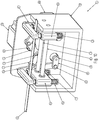
- Figs 1-9 show a structure and operation of a feeding apparatus.
- the described arrangement of the feeding apparatus feeds a workpiece such as metal sheets or wire, or the like to a press machine, stamping machine or the like. It should be understood that the feeding apparatus may be used with other materials or in combination with other types of machines requiring the intermittent feeding of a workpiece.
- a feeding apparatus 1 depicted generally in FIG. 1 , is provided with a frame 2.
- a workpiece 100 is illustrated and a first direction of workpiece feeding is depicted with a direction arrow.
- a first gripper mechanism 3 is supported by and configured for linear movement along linear guides 50 and 51.
- Linear guides 50 and 51 are supported by frame 2 and stationary relative thereto.
- linear guides 50 and 51 are parallel cylindrical rods.
- Linear guides 50 and 51 are arranged parallel to the direction of workpiece feeding.
- First gripper mechanism 3 is therefore linearly guided and movable in a first direction of workpiece feeding and in a direction opposite to the first direction of workpiece feeding.
- First gripper mechanism 3 comprises a first gripping member 30 and a second gripping member 15. Second gripping member 15 is movable relative to first gripping member 30. Further, in this arrangement, first gripper mechanism 3 further comprises a first spring 18 and a second spring 19. First and second springs 18 and 19 are arranged for urging second gripping member 15 toward gripping member 30. Alternatively either first spring 18 or second spring 19 or both may be omitted.
- a second gripper mechanism 4 is supported by frame 2 and stationary relative thereto.
- Second gripper mechanism 4 comprises a first gripping member 40 and a second gripping member 25.
- Second gripping member 25 is movable relative to first gripping member 40.
- second gripper mechanism 4 further comprises a first spring 28 and a second spring 29.
- First and second springs 28 and 29 are arranged for urging second gripping member 25 toward gripping member 40.
- first spring 28 or second spring 29 or both may be omitted.
- a gripper mechanism drive actuator 60 is supported by frame 2 and stationary relative thereto.
- Gripper mechanism drive actuator 60 is angularly adjustable, reversible and rotary.
- Gripper mechanism drive actuator 60 is preferably a brushless permanent magnet electric servo motor.
- gripper mechanism drive actuator 60 may be a stepper motor, a hydraulic motor, a rotary pneumatic actuator, or any reversible rotary actuator that may be adjustable in angle of rotation.
- Gripper mechanism drive actuator 60 is controlled by a programmable controller 91 ( FIG. 9 ).
- Programmable controller 91 is configured for adjusting the rotation angle of the gripper mechanism drive actuator 60.
- the rotation angle of gripper mechanism drive actuator 60 is therewith controlled and thereby adjustable.
- gripper mechanism drive actuator 60 is an angularly adjustable, reversible and rotary actuator.
- Programmable controller 91 depicted generally in the drawings is of conventional design well known in the art. Programmable controller 91 is connected to gripper mechanism drive actuator 60 with a wire 94.
- a drive link or driving member 34 is connected to output shaft 35 of gripper mechanism drive actuator 60 for rotation therewith.
- Driving member 34 being connected to output shaft 35 for rotation therewith, rotates about a rotation axis 36 of output shaft 35. It should be noted that while driving member 34 is shown as a separate component from output shaft 35 of gripper mechanism drive actuator 60, driving member 34 could be constructed as an integral part of output shaft 35, such as an eccentric feature of output shaft 35.
- a gripper mechanism drive connecting link 32 is pivotally connected at a first end by connecting pin 33 to a first end of driving member 34 at a first pivot axis 37 and at a second end by connecting pin 31 to movable gripper mechanism 3 at a second pivot axis 38.
- a release actuator 71 depicted generally in FIG 7 ., is supported by frame 2 and stationary relative thereto. Release actuator 71 is preferably reversible. Release actuator 71 comprises a reversible motor 70 with output shaft 10 and a drive link or driving member 11 connected to output shaft 10 of motor 70 for rotation therewith. It should be noted that while driving member 11 is shown as a separate component from output shaft 10, driving member 11 could be constructed as an integral part of output shaft 10, such as an eccentric feature of output shaft 10.
- Reversible motor 70 is preferably a brushless permanent magnet electric servo motor controlled by a programmable controller 92.
- reversible motor 70 is an electric stepper motor, a hydraulic motor, or a rotary pneumatic actuator.
- Programmable controller 92 depicted generally in the drawings is of conventional design well known in the art. Programmable controller 92 is connected with a wire 94 in a particular sense to motor 70 and in a more general sense to release actuator 71.
- a release connecting link 13 ( Fig. 2 ) with a first end is pivotally connected at the first end by connecting pin 12 to driving member 11 of release actuator 71 at a first pivot axis 16.
- a second end of release connecting link 13 is pivotally connected by connecting pin 14 to second gripping member 15 of the first gripper mechanism 3 at a second pivot axis 17.
- the arrangement of the release connecting link 13 and second pivot axis 17 is such that the second pivot axis 17 is arranged generally perpendicular to the direction of movement of the second gripping member 15 of the first gripper mechanism 3 relative to the first gripping member 30 of the first gripper mechanism 3 and is further arranged generally perpendicular to the first direction of workpiece feeding.
- the second pivot axis 17 of the first gripper mechanism 3 is movable in the direction of workpiece feeding and in the direction opposite to the direction of workpiece feeding.
- a release actuator 81 depicted generally in FIG 8 ., is supported by frame 2 and stationary relative thereto. Release actuator 81 is preferably reversible. Release actuator 81 comprises a reversible motor 80 with output shaft 20 and a drive link or driving member 21 connected to output shaft 20 of motor 80 for rotation therewith. It should be noted that while driving member 21 is shown as a separate component from output shaft 20, driving member 21 could be constructed as an integral part of output shaft 20, such as an eccentric feature of output shaft 10.
- Reversible motor 80 is preferably a brushless permanent magnet electric servo motor controlled by a programmable controller 93.
- reversible motor 80 is an electric stepper motor, a hydraulic motor, or a rotary pneumatic actuator.
- Programmable controller 93 depicted generally in the drawings is of conventional design well known in the art. Programmable controller 93 is connected with a wire 96 in a particular sense to motor 80 and in a more general sense to release actuator 81.
- a release connecting link 23 with a first end is pivotally connected at the first end by connecting pin 22 to driving member 21 of release actuator 81 at a first pivot axis 26 and at a second end by connecting pin 24 to second gripping member 25 at a second pivot axis 27.
- release actuator 71 cooperates with springs 18 and 19 to move second gripping member 15 towards first gripping member 30 for gripping workpiece 100.
- release actuator 71 moves second gripping member 15 towards first gripping member 30 for gripping workpiece 100.
- output shaft 10 of reversible motor 70 is rotated to move driving member 11, connecting pins 12 and 14, and release connecting link 13 such that second gripping member 15 is moved into contact with workpiece 100 thereby gripping the workpiece 100 between second gripping member 15 and first gripping member 30.
- Release actuator 81 moves second gripping member 25 away from first gripping member 40 for releasing a grip on workpiece 100.
- output shaft 20 of motor 80 is rotated to move driving member 21, connecting pins 22 and 24, and release connecting link 23 such that second gripping member 25 is moved away from workpiece 100 thereby releasing workpiece 100 from second gripping member 25 and first gripping member 40.
- Figure 3 illustrates the feeding apparatus in this state.
- Reversible rotary gripper mechanism drive actuator 60 is rotated to move driving member 34, connecting pins 31 and 33, and gripper mechanism drive connecting link 32 such that first gripper mechanism 3 and workpiece 100 is moved in a first direction of workpiece feeding as depicted by an arrow in the drawings.
- the feeding distance of workpiece 100 is determined by the rotational angle of rotary gripper mechanism drive actuator 60 and driving member 34.
- rotary gripper mechanism drive actuator 60 is preferably a brushless permanent magnet electric servo motor commanded by programmable controller 91, the rotation angle of gripper mechanism drive actuator 60 and therefore the feeding distance of workpiece 100 is easily adjusted.
- FIG. 4 illustrates the feeding apparatus in this state.
- Release actuator 81 cooperates with springs 28 and 29 to move second gripping member 25 towards first gripping member 40 for a gripping of the workpiece 100.
- release actuator 81 moves second gripping member 25 towards first gripping member 40 for gripping workpiece 100.
- output shaft 20 of motor 80 is rotated to move driving member 21, connecting pins 22 and 24, and release connecting link 23 such that second gripping member 25 is moved into contact with workpiece 100 thereby gripping the workpiece 100 between second gripping member 25 and first gripping member 40.
- Release actuator 71 moves second gripping member 15 away from first gripping member 30 for releasing a gripping force on workpiece 100.
- output shaft 10 of reversible motor 70 is rotated to move driving member 11, connecting pins 12 and 14, and release connecting link 13 such that second gripping member 15 is moved away from workpiece 100 thereby releasing workpiece 100 from second gripping member 15 and first gripping member 30. That is, by the actuation of release actuator 71, the second gripping member 15 is moved in a direction relative to first gripping member 30 and in a direction generally perpendicular to the first direction of workpiece feeding.
- Figure 5 illustrates the feeding apparatus in this state.
- Reversible rotary gripper mechanism drive actuator 60 is rotated to move driving member 34, connecting pins 31 and 33, and gripper mechanism drive connecting link 32 such that first gripper mechanism 3 is moved in a second direction opposite to the first direction of workpiece feeding.
- Figure 6 illustrates the feeding apparatus in this state.
- the operation is periodically repeated in synchronization with the stamping machine or the like.
- release actuator 81 may be used to release the workpiece from second gripper mechanism 4 to allow for a piloting or final positioning operation of a tool or the like in the stamping machine or the like.
- actuator 80 may be operated in a manner to open second gripping member 25 to release workpiece 100 prior to the operation of release actuator 71 and the subsequent closing of second gripping member 15 to allow for the piloting or final positioning operation of a tool or the like in the stamping machine or the like.
- release actuator 71 will move.
- the movement of release actuator 71 is such that release connecting link 13, connecting pin 12, connecting pin 14 and therefore pivot axis 17 is moved such that the distance between second gripping member 15 and first gripping member 30 is constant.
- Programmable controller 92 is configured for this function.
- programmable controller 92 may be configured to control release actuator 71 in a similar manner to move pivot axis 17 such that the opening distance between first and second gripping members 30 and 15 respectively remains constant while first gripper mechanism 3 is moving the second direction opposite to the first direction of workpiece feeding.
- gripping force exerted by gripping members 15 onto workpiece 100 may be determined by a force produced by release actuator 71 and controlled by programmable controller 92.
- programmable controller 92 and release actuator 71 may be used to determine the distance between gripping member 15 and gripping member 30 thereby providing a gap between the workpiece 100 and gripping member 15 during the times when first gripper mechanism 3 is stopped or moving in a second direction opposite to the first direction.
- the distance between the gripping members and therefore the gap between workpiece 100 and gripping member 15 may be specifically optimized for different thicknesses of workpiece 100.
- Figs 10-18 show a structure and operation of a feeding apparatus
- the described arrangement of the feeding apparatus feeds a workpiece such as metal sheets or wire, or the like to a press machine, stamping machine or the like. It should be understood that the feeding apparatus may be used with other materials or in combination with other types of machines requiring the intermittent feeding of workpiece.
- a feeding apparatus 101 depicted generally in Fig. 10 , is provided with a frame 102.
- a workpiece 100 is illustrated and a first direction of workpiece feeding is depicted with a direction arrow.
- a first gripper mechanism 103 is supported by and configured for linear movement along linear guides 150 and 151.
- Linear guides 150 and 151 are supported by frame 102 and stationary relative thereto.
- linear guides 150 and 151 are parallel cylindrical rods.
- Linear guides 150 and 151 are arranged parallel to the direction of workpiece feeding.
- First gripper mechanism 103 is therefore linearly guided and movable in a first direction of workpiece feeding and in a direction opposite to the first direction of workpiece feeding.
- First gripper mechanism 103 comprises a first gripping member 130 and a second gripping member 115. Second gripping member 115 is movable relative to first gripping member 130. Further, in this arrangement, first gripper mechanism 103 further comprises a first spring 118 and a second spring 119. First and second springs 118 and 119 are arranged for urging second gripping member 115 toward gripping member 130. Alternatively either first spring 118 or second spring 119 or both may be omitted.
- a second movable gripper mechanism 104 is supported by and configured for linear movement along the linear guides 150 and 151.
- Second gripper mechanism 104 comprises a first gripping member 140 and a second gripping member 125.
- Second gripping member 125 is movable relative to first gripping member 140.
- second gripper mechanism 104 further comprises a first spring 128 and a second spring 129.
- First and second springs 128 and 129 are arranged for urging second gripping member 125 toward gripping member 140.
- first spring 128 or second spring 129 or both may be omitted.
- a reversible rotary gripper mechanism drive actuator 160 is supported by frame 102 and stationary relative thereto.
- Reversible rotary gripper mechanism drive actuator 160 is preferably a brushless permanent magnet electric servo motor.
- reversible rotary gripper mechanism drive actuator 160 may be a stepper motor, a hydraulic motor, a rotary pneumatic actuator, or any reversible rotary actuator that may be adjustable in angle of rotation.
- Reversible rotary gripper mechanism drive actuator 160 is controlled by a programmable controller 191 ( Fig. 18 ).
- Programmable controller 91 is configured for adjusting the rotation angle of the gripper mechanism drive actuator 160.
- the rotation angle of reversible rotary gripper mechanism drive actuator 160 is therewith controlled and thereby adjustable. That is, gripper mechanism drive actuator 160 is an angularly adjustable rotary actuator.
- Programmable controller 191, depicted generally in the drawings is of conventional design well known in the art. Programmable controller 91 is connected to actuator 161 with a wire 194
- a drive link or driving member 134 is connected to output shaft 135 of reversible rotary gripper mechanism drive actuator 160 for rotation therewith.
- Driving member 134 being connected to output shaft 135 for rotation therewith rotates about a rotation axis 136 of output shaft 135. It should be noted that while driving member 134 is shown as a separate component from output shaft 135 of reversible rotary gripper mechanism drive actuator 160, driving member 134 could be constructed as an integral part of output shaft 135, such as an eccentric feature of output shaft 135.
- a first gripper mechanism drive connecting link 132 is pivotally connected at a first end by connecting pin 133 to a first end of driving member 134 at a first pivot axis 137 and at a second end by connecting pin 131 to movable gripper mechanism 103 at a second pivot axis 138.
- a second gripper mechanism drive connecting link 142 is pivotally connected at a first end by connecting pin 143 to a second end of driving member 134 at a first pivot axis 147 and at a second end by connecting pin 141 to movable gripper mechanism 104 at a second pivot axis 148.
- driving member 134 is a fixed length driving member.
- the rotation axis 136 of output shaft 135 and due to the connection of driving member 134 thereto, is located at the midpoint between the first pivot axis 137 and third pivot axis 147.
- gripper mechanism drive connecting link 142 and gripper mechanism drive connecting link 132 are equal in length.
- Release actuator 171 is supported by frame 102 and stationary relative thereto. Release actuator 171 is preferably reversible. Release actuator 171 comprises a reversible motor 170 with output shaft 110 and a driving link or driving member 111 connected to output shaft 110 of motor 170 for rotation therewith. It should be noted that while driving member 111 is shown as a separate component from output shaft 110, driving member 111 could be constructed as an integral part of output shaft 110, such as an eccentric feature of output shaft 110.
- Reversible motor 170 is preferably a brushless permanent magnet electric servo motor controlled by a programmable controller 192.
- reversible motor 170 is an electric stepper motor, a hydraulic motor, or a rotary pneumatic actuator.
- Programmable controller 192 depicted generally in the drawings is of conventional design well known in the art. Programmable controller 192 is connected with a wire 194 in a particular sense to motor 170 and in a more general sense to release actuator 171.
- a release connecting link 113 ( FIG. 11 ) is pivotally connected at a first end by connecting pin 112 to driving member 111 at a first pivot axis 116 and at a second end by connecting pin 114 to second gripping member 115 at a second pivot axis 117.
- the arrangement of the release connecting link 113 and second pivot axis 117 is such that the second pivot axis 117 is arranged generally perpendicular to the direction of movement of the second gripping member 115 of the first gripper mechanism 103 relative to the first gripping member 130 of the first gripper mechanism 103 and is further arranged generally perpendicular to the first direction of workpiece feeding.
- the second pivot axis 117 of the first gripper mechanism 103 is movable in the direction of workpiece feeding and in the direction opposite to the direction of workpiece feeding.
- Release actuator 181 depicted generally in FIG 17 ., is supported by frame 102 and stationary relative thereto. Release actuator 181 is preferably reversible. Release actuator 181 comprises a reversible motor 180 with output shaft 120 and a drive link or driving member 121 connected to output shaft 120 of motor 180 for rotation therewith. It should be noted that while driving member 121 is shown as a separate component from output shaft 120, driving member 121 could be constructed as an integral part of output shaft 120, such as an eccentric feature of output shaft 120.
- Reversible motor 180 is preferably a brushless permanent magnet electric servo motor controlled by a programmable controller 193.
- reversible motor 180 is an electric stepper motor, a hydraulic motor, or a rotary pneumatic actuator.
- Programmable controller 193, depicted generally in the drawings is of conventional design well known in the art. Programmable controller 193 is connected with a wire 196 in a particular sense to motor 180 and in a more general sense to release actuator 181.
- a release connecting link 123 is pivotally connected at a first end by connecting pin 122 to driving member 121 at a first pivot axis 126 and at a second end by connecting pin 124 to second gripping member 125 at a second pivot axis 127.
- the arrangement of the release connecting link 123 and second pivot axis 127 is such that the second pivot axis 127 is arranged generally perpendicular to the direction of movement of the second gripping member 125 of the first gripper mechanism 104 relative to the first gripping member 140 of the first gripper mechanism 104 and is further arranged generally perpendicular to the first direction of workpiece feeding.
- the second pivot axis 127 of the first gripper mechanism 104 is movable in the direction of workpiece feeding and in the direction opposite to the direction of workpiece feeding.
- release actuator 171 cooperates with springs 118 and 119 to move second gripping member 115 towards first gripping member 130 for gripping workpiece 100.
- release actuator 171 moves second gripping member 115 towards first gripping member 130 for gripping workpiece 100.
- output shaft 110 of reversible motor 170 is rotated to move driving member 111, connecting pins 112 and 114, and release connecting link 113 such that second gripping member 115 is moved into contact with workpiece 100 thereby gripping the workpiece 100 between second gripping member 115 and first gripping member 130.
- Release actuator 181 moves second gripping member 125 away from first gripping member 140 for releasing a grip on workpiece 100.
- output shaft 120 of motor 180 is rotated to move driving member 121, connecting pins 122 and 124, and release connecting link 123 such that second gripping member 125 is moved away from workpiece 100 thereby releasing workpiece 100 from second gripping member 125 and first gripping member 140.
- Figure 12 illustrates the feeding apparatus in this state.
- Reversible rotary gripper mechanism drive actuator 160 is rotated to move driving member 134, connecting pins 131 and 133, and gripper mechanism drive connecting link 132 such that first gripper mechanism 103 and workpiece 100 is moved in a first direction of workpiece feeding as depicted by an arrow in the drawings.
- the feeding distance of workpiece 100 is determined by the rotational angle of rotary gripper mechanism drive actuator 160 and driving member 134.
- rotary gripper mechanism drive actuator 160 is preferably a brushless permanent magnet electric servo motor controlled by programmable controller 191
- the rotation angle of rotary gripper mechanism drive actuator 160 and therefore the feeding distance of workpiece 100 is easily adjusted.
- connecting pins 141 and 143, and gripper mechanism drive connecting link 142 is moved by driving member 134 such that the second gripper mechanism 104 is moved in a second direction opposite to the first direction of workpiece feeding.
- Release actuator 181 cooperates with springs 128 and 129 to move second gripping member 125 towards first gripping member 140 for a gripping of the workpiece 100.
- release actuator 181 moves second gripping member 125 towards first gripping member 140 for gripping workpiece 100.
- output shaft 120 of motor 180 is rotated to move driving member 121, connecting pins 122 and 124, and release connecting link 123 such that second gripping member 125 is moved into contact with workpiece 100 thereby gripping the workpiece 100 between second gripping member 124 and first gripping member 140.
- Release actuator 171 moves second gripping member 115 away from first gripping member 130 for releasing a gripping force on workpiece 100.
- output shaft 110 of motor 170 is rotated to move driving member 111, connecting pins 112 and 114, and release connecting link 113 such that second gripping member 115 is moved away from workpiece 100 thereby releasing workpiece 100 from second gripping member 115 and first gripping member 130. That is, by actuation of release actuator 171, the second gripping member 115 is moved in a direction relative to first gripping member 130 and in a direction generally perpendicular to the first direction of workpiece feeding.
- Figure 14 illustrates the feed apparatus in this state.
- Reversible rotary gripper mechanism drive actuator 160 is rotated to move driving member 134, connecting pins 141 and 143, and gripper mechanism drive connecting link 142 such that second gripper mechanism 104 is moved in the first feeding direction of workpiece 100.
- the feeding distance of workpiece 100 is determined by the rotational angle of rotary gripper mechanism drive actuator 160 and driving member 134.
- connecting pins 131 and 133, and gripper mechanism drive connecting link 132 is moved by driving member 134 such that first gripper mechanism 103 is moved in a direction opposite to the first feeding direction of workpiece 100.
- Figure 15 illustrates the feed apparatus in this state.
- the operation is periodically repeated in synchronization with the stamping machine or the like.
- actuators 171 and 181 may be used to release the workpiece from both first and second movable gripper mechanisms 103 and 104 to allow for a piloting or final positioning operation of a tool or the like in the stamping machine or the like.
- Figs 19 and 20 illustrate alternative constructions of the actuators previously designated 71, 81, 171, and 181.
- An actuator 271 in accordance with the present invention is supported by frame 2 and stationary relative thereto.
- Actuator 271 is reversible.
- Actuator 271 comprises a reversible motor 270 with output shaft 210 and a threaded rod 211 connected to output shaft 210 of motor 270 with coupling 216 for rotation therewith.
- threaded rod 211 is shown as a separate component from output shaft 210, threaded rod 211 could be constructed as an integral part of output shaft 210 and with coupling 216 eliminated.
- Reversible motor 270 is preferably a brushless permanent magnet electric servo motor controlled by the programmable controller 92.
- reversible motor 270 is an electric stepper motor, a hydraulic motor, or a rotary pneumatic actuator.
- Actuator 271 further comprises an internally threaded member 215. Threaded rod 211 and internally threaded member 215 cooperated to produce a linear movement of internally threaded member 215 upon rotation of threaded rod 211.
- the threads of threaded rod 211 and internally threaded member 215 are preferable of a trapezoidal type power thread. Alternatively the threads of threaded rod 211 and internally threaded member 215 could be of standard triangular type. Alternatively threaded rod 211 could be a ball screw and internally threaded member 215 a re-circulating ball nut.
- Release connecting link 13 is at the first end pivotally connected by the connecting pin 12 to internally threaded member 215.
- Actuator 371 is supported by frame 2 and stationary relative thereto.
- Actuator 371 is preferable reversible.
- Actuator 371 comprises a reversible linear actuator 370 with a thrusting member 310 arranged for linear movement.
- Reversible linear actuator 370 is preferably a linear electric motor controlled by the programmable controller 92.
- reversible linear actuator 370 is a linear stepper motor, an electric solenoid, a hydraulic cylinder, a pneumatic cylinder, or any reversible linear actuator that comprises a thrusting member with linear movement.
- Release connecting link 13 is at the first end pivotally connected by the connecting pin 12 to linear thrusting member 310.
- Alternative actuators 271 and 371 may be operated to provide a substantively equivalent function to that of actuators 71, 81, 171 and 181.
- the apparatus is described as having an actuator and link arrangement for the opening or closing of second gripper mechanism 4 similar to that used for the opening or closing of first gripper mechanism 2, that is with a motor 80, a driving member 21 and a release connecting link 23, the stationary arrangement of second gripper mechanism 4 may allow for omission of a connecting link.
- Such arrangements do not depart from the spirit of, or exceed the scope of the claimed invention.
- the arrangement presented represents a preferred arrangement in that common components may be used in the functionally corresponding components of the actuator and link arrangement providing the opening or closing functions of first gripper mechanism 3 and second gripper mechanism 4 thereby reducing the number of different components to be manufactured.
- controllers referenced herein being 91, 92, and 93.
- controllers referenced herein being 191, 192, and 193.
Landscapes
- Engineering & Computer Science (AREA)
- Mechanical Engineering (AREA)
- Manipulator (AREA)
- Jigs For Machine Tools (AREA)
- Advancing Webs (AREA)
- Specific Conveyance Elements (AREA)
Claims (10)
- Appareil pour l'alimentation intermittente d'une pièce, l'appareil comprenant :un premier mécanisme de préhension (3 ; 103) guidé linéairement qui est mobile dans une première direction d'alimentation de la pièce et dans une seconde direction opposée à la première direction,le premier mécanisme de préhension (3 ; 103) comprenant un premier élément de préhension (30 ; 130) et un second élément de préhension (15 ; 115), le second élément de préhension (15 ; 115) étant mobile par rapport au premier élément de préhension (30 ; 130) pour saisir la pièce ;un premier actionneur de libération (71; 171; 271; 371) pour déplacer le second élément de préhension (15 ; 115) du premier mécanisme de préhension (3 ; 103) dans une direction par rapport au premier élément de préhension (30 ; 130) du premier mécanisme de préhension (3 ; 103) ;une première biellette de libération (13 ; 113) avec une première extrémité reliée de manière pivotante au niveau d'un premier axe de pivotement (16; 116) au premier actionneur de libération (71 ; 171 ; 271 ; 371) et avec une seconde extrémité reliée de manière pivotante au niveau d'un second axe de pivotement (17; 117) au second élément de préhension (15 ; 115) du premier mécanisme de préhension (3 ; 103), etun premier dispositif de commande programmable (92; 192) pour commander l'actionnement du premier actionneur de libération (71 ; 171 ; 271 ; 371) ;le second axe de pivotement (17 ; 117) de la première biellette de libération (13 ; 113) étant mobile dans la première direction d'alimentation de la pièce et la seconde direction opposée à la première direction ;le premier actionneur de libération (71 ; 171 ; 271 ; 371) étant réversible ;caractérisé en ce que le premier actionneur de libération réversible (271) comprend un moteur rotatif (270), une tige filetée (211), et un élément fileté intérieurement (215);
l'élément fileté intérieurement (215) étant relié à la première biellette de libération (13 ; 113) au niveau du premier axe de pivotement (16 ; 116). - Appareil selon la revendication 1, la direction de déplacement du second élément de préhension (15 ; 115) du premier mécanisme de préhension (3 ; 103) par rapport au premier élément de préhension (30 ; 130) du premier mécanisme de préhension (3 ; 103) étant généralement perpendiculaire à la première direction d'alimentation de la pièce.
- Appareil selon la revendication 1, le second axe de pivotement (17; 117) de la première biellette de libération (13 ; 113) étant disposé généralement perpendiculairement à la direction de déplacement du second élément de préhension (15 ; 115) du premier mécanisme de préhension (3 ; 103) par rapport au premier élément de préhension (30 ; 130) du premier mécanisme de préhension (3 ; 103) et étant en outre disposé généralement perpendiculairement à la première direction d'alimentation de la pièce.
- Appareil selon la revendication 1, le premier actionneur de libération (71 ; 171 ; 271) et le dispositif de commande programmable (92) étant conçus pour produire une force de préhension sur la pièce.
- Appareil selon la revendication 1, le premier actionneur de libération (71 ; 171 ; 271) et le dispositif de commande programmable (92) étant conçus pour déterminer une distance entre les premier et second éléments de préhension (15, 30) du premier mécanisme de préhension (3 ; 103) de sorte qu'un espace soit créé entre la pièce et le second élément de préhension (15 ; 115) qui est optimal pour une épaisseur de pièce.
- Appareil selon la revendication 1, le premier dispositif de commande programmable (92) étant conçu pour déplacer le second axe de pivotement (17 ; 117) de la première biellette de libération (13 ; 113) avant le mouvement du premier mécanisme de préhension (3 ; 103) dans la première direction d'alimentation de la pièce de sorte que la distance entre les premier et second éléments de préhension (15, 30) du premier mécanisme de préhension (3 ; 103) soit réduite pour saisir la pièce.
- Appareil selon la revendication 1, le premier dispositif de commande programmable (92) étant conçu pour déplacer le second axe de pivotement (17 ; 117) de la première biellette de libération (13 ; 113) pendant le mouvement du premier mécanisme de préhension (3 ; 103) dans la première direction d'alimentation de la pièce de sorte que la distance entre les premier et second éléments de préhension (15, 30) du premier mécanisme de préhension (3 ; 103) reste constante.
- Appareil selon la revendication 1, le premier dispositif de commande programmable étant conçu pour déplacer le second axe de pivotement (17 ; 117) de la première biellette de libération (13 ; 113) à la fin du mouvement du premier mécanisme de préhension (3 ; 103) dans la première direction d'alimentation de la pièce de sorte que la distance entre les premier et second éléments de préhension (15, 30) du premier mécanisme de préhension (3 ; 103) soit augmentée pour libérer la pièce.
- Appareil selon la revendication 1, le premier dispositif de commande programmable (92) étant conçu pour déplacer le second axe de pivotement (17 ; 117) de la première biellette de libération (13 ; 113) pendant le mouvement du premier mécanisme de préhension (3 ; 103) dans la seconde direction opposée à la première direction d'alimentation de la pièce de sorte que la distance entre les premier et second éléments de préhension (15, 30) du premier mécanisme de préhension (3 ; 103) reste constante.
- Appareil selon la revendication 1, comprenant en outre :un second mécanisme de préhension (4; 104) guidé linéairement qui est mobile dans une première direction d'alimentation de la pièce et dans une seconde direction opposée à la première direction,le second mécanisme de préhension (4; 104) comprenant un premier élément de préhension (40 ; 140) et un second élément de préhension (25; 125), le second élément de préhension (25; 125) étant mobile par rapport au premier élément de préhension (40; 140) pour saisir la pièce ; etun second actionneur de libération (81; 181) pour déplacer le second élément de préhension (25; 125) du second mécanisme de préhension (4 ; 104) dans une direction par rapport au premier élément de préhension (40 ; 140) du second mécanisme de préhension (4 ; 104) ; etune seconde biellette de libération (23; 123) avec une première extrémité reliée de manière pivotante au niveau d'un premier axe de pivotement (26 ; 126) au second actionneur de libération (81 ; 181) et avec une seconde extrémité reliée de manière pivotante au niveau d'un second axe de pivotement (27; 127) au second élément de préhension (25; 125) du premier mécanisme de préhension (4 ; 104) ; etle second axe de pivotement (27 ; 127) de la seconde biellette de libération (23 ; 123) étant mobile dans la première direction d'alimentation de la pièce et la seconde direction opposée à la première direction
Applications Claiming Priority (2)
| Application Number | Priority Date | Filing Date | Title |
|---|---|---|---|
| US25655609P | 2009-10-30 | 2009-10-30 | |
| PCT/US2010/054969 WO2011053911A1 (fr) | 2009-10-30 | 2010-11-01 | Appareil d'alimentation en matériau comportant une liaison d'un organe de préhension et procédé de fonctionnement |
Publications (3)
| Publication Number | Publication Date |
|---|---|
| EP2493797A1 EP2493797A1 (fr) | 2012-09-05 |
| EP2493797A4 EP2493797A4 (fr) | 2017-01-04 |
| EP2493797B1 true EP2493797B1 (fr) | 2021-05-19 |
Family
ID=43922612
Family Applications (2)
| Application Number | Title | Priority Date | Filing Date |
|---|---|---|---|
| EP10827603.1A Active EP2493797B1 (fr) | 2009-10-30 | 2010-11-01 | Appareil d'alimentation de matériaux avec liaison pour organe de serrage |
| EP10827604.9A Not-in-force EP2493636B1 (fr) | 2009-10-30 | 2010-11-01 | Appareil d'alimentation de matière muni d'un organe d'entraînement préhenseur et d'une liaison |
Family Applications After (1)
| Application Number | Title | Priority Date | Filing Date |
|---|---|---|---|
| EP10827604.9A Not-in-force EP2493636B1 (fr) | 2009-10-30 | 2010-11-01 | Appareil d'alimentation de matière muni d'un organe d'entraînement préhenseur et d'une liaison |
Country Status (7)
| Country | Link |
|---|---|
| US (2) | US9090426B2 (fr) |
| EP (2) | EP2493797B1 (fr) |
| JP (2) | JP5803040B2 (fr) |
| KR (3) | KR101661009B1 (fr) |
| CN (3) | CN102648061B (fr) |
| TW (2) | TWI530339B (fr) |
| WO (2) | WO2011053912A1 (fr) |
Families Citing this family (31)
| Publication number | Priority date | Publication date | Assignee | Title |
|---|---|---|---|---|
| JP5803040B2 (ja) | 2009-10-30 | 2015-11-04 | ヴァムコ・インターナショナル・インコーポレイテッド | グリッパ駆動用部材及びリンク装置を有する材料送り装置 |
| TW201348103A (zh) * | 2012-05-23 | 2013-12-01 | Hiwin Tech Corp | 送料裝置 |
| ITMO20120155A1 (it) * | 2012-06-15 | 2013-12-16 | Kemet Electronics Italia S R L | Metodo e apparato per lavorare materiale in nastro |
| CN104495458B (zh) * | 2014-12-20 | 2016-08-17 | 桐梓县创兴自动化设备有限公司 | 一种用于布匹的曲柄式间歇传送装置 |
| CN104891238B (zh) * | 2015-05-28 | 2016-09-07 | 成都宏明双新科技股份有限公司 | 一种双带料送料装置 |
| JP6572024B2 (ja) * | 2015-07-02 | 2019-09-04 | 株式会社タカゾノテクノロジー | 薬剤包装装置 |
| CN107415212B (zh) * | 2015-07-16 | 2019-08-30 | 佛山威明塑胶有限公司 | 一种超薄pvc薄膜的拉膜机 |
| US10232169B2 (en) | 2015-07-23 | 2019-03-19 | Boston Scientific Neuromodulation Corporation | Burr hole plugs for electrical stimulation systems and methods of making and using |
| US10988330B2 (en) | 2016-09-08 | 2021-04-27 | Hewlett-Packard Development Company, L.P. | Media size detector |
| CN106882625B (zh) * | 2017-04-21 | 2018-07-17 | 长兴鼎峰铸材科技股份有限公司 | 一种冒口包装用自动输纸机构 |
| CN107826838B (zh) * | 2017-11-02 | 2019-09-10 | 上海继林机电科技有限公司 | 一种贴胶布传输机构 |
| CN111344042B (zh) | 2017-11-13 | 2023-09-26 | 波士顿科学神经调制公司 | 制造和使用电刺激系统的低剖面控制模块的系统和方法 |
| US11497914B2 (en) | 2018-01-16 | 2022-11-15 | Boston Scientific Neuromodulation Corporation | Systems and methods for making and using an electrical stimulation system with a case-neutral battery |
| WO2019173281A1 (fr) | 2018-03-09 | 2019-09-12 | Boston Scientific Neuromodulation Corporation | Chevilles de trous pratiqués à l'aide d'une fraise pour systèmes de stimulation électrique |
| US11013913B2 (en) | 2018-03-16 | 2021-05-25 | Boston Scientific Neuromodulation Corporation | Kits and methods for securing a burr hole plugs for stimulation systems |
| CN108439003B (zh) * | 2018-03-27 | 2024-12-06 | 湖北玥研科技有限公司 | 模切机 |
| CN110027932B (zh) * | 2019-04-30 | 2024-03-15 | 广东利元亨智能装备股份有限公司 | 一种带料输送设备 |
| US12064824B1 (en) | 2019-07-11 | 2024-08-20 | HE&M Inc. | Feed indexing for material handling apparatus and process therefor |
| CN110803561B (zh) * | 2019-11-29 | 2025-08-29 | 晶澳(邢台)太阳能有限公司 | 一种夹式上料装置及夹式上料机 |
| CN111824827B (zh) * | 2020-06-10 | 2021-11-05 | 桐乡市中瑞环保科技有限公司 | 一种熔喷布传送机构 |
| CN111824828B (zh) * | 2020-06-10 | 2021-11-05 | 桐乡市中瑞环保科技有限公司 | 一种熔喷布传送加工装置 |
| CN112404296A (zh) * | 2020-11-02 | 2021-02-26 | 长沙衡开智能科技有限公司 | 一种双头层绕机焊丝折弯机构 |
| CN112719158A (zh) * | 2020-12-03 | 2021-04-30 | 安徽理工大学 | 一种线材间歇进给装置 |
| CN113385618B (zh) * | 2021-07-16 | 2024-07-12 | 浙江核芯流体装备有限公司 | 一种新型异形线导向器 |
| CN113816179A (zh) * | 2021-10-29 | 2021-12-21 | 杨爱东 | 一种翻布机自动拉拽装置 |
| WO2023083450A1 (fr) * | 2021-11-11 | 2023-05-19 | Bruderer Ag | Procédé et dispositif de fourniture intermittente d'un matériau semi-fini en forme de bande ou de fil à une presse |
| CN114101463B (zh) * | 2021-11-30 | 2022-08-23 | 浙江巨宏机械科技有限公司 | 一种蓄电池端子自动加工设备 |
| US11818192B2 (en) * | 2022-02-28 | 2023-11-14 | Nvidia Corporation | Encoding output for streaming applications based on client upscaling capabilities |
| CN116618515B (zh) * | 2023-06-27 | 2026-04-14 | 深圳愚工智能装备有限公司 | 一种连杆式冲孔及输送机构 |
| CN117324533A (zh) * | 2023-10-13 | 2024-01-02 | 北京新光凯乐汽车冷成型件股份有限公司 | 一种冷镦机原料夹送辅助装置 |
| CN117531859A (zh) * | 2023-12-20 | 2024-02-09 | 无锡德宇环创自动化科技有限公司 | 一种轧尖机的上料进给装置 |
Family Cites Families (35)
| Publication number | Priority date | Publication date | Assignee | Title |
|---|---|---|---|---|
| US2803456A (en) | 1955-10-18 | 1957-08-20 | Todd C | Slide feed with toggle actuated gripper |
| US3289507A (en) | 1964-11-20 | 1966-12-06 | Ekco Containers Inc | Self-correcting feed device for preprinted sheet stock |
| US3707255A (en) | 1971-01-13 | 1972-12-26 | Minster Machine Co | Feed arrangement for strip stack |
| JPS5421812Y2 (fr) * | 1972-10-16 | 1979-08-01 | ||
| DE2454460A1 (de) * | 1974-11-16 | 1976-05-20 | Grau Erich Stanzwerk Elek | Vorschubvorrichtung zur intermittierenden materialzufuhr an stanzen oder pressen |
| DE2460168B2 (de) | 1974-12-19 | 1976-12-09 | Th. Kieserling & Albrecht, 5650 Solingen | Spann- und auszugseinrichtung fuer schaelmaschinen, ziehbaenke und dergleichen bearbeitungsmaschinen |
| FR2474357A1 (fr) * | 1980-01-24 | 1981-07-31 | Normatic Sa | Dispositif pour deplacer des produits en bobines ou en barres vers une machine |
| US4347961A (en) | 1981-02-23 | 1982-09-07 | Smith Frank G | Rapid advance long dwell feed mechanism for multiple slide machines |
| DE3240860A1 (de) | 1982-11-05 | 1984-05-10 | Hans 4320 Hattingen Schoen | Zangenvorschubeinrichtung fuer bearbeitungsmaschinen, insbesondere stanzpressen oder dergleichen |
| DE3247001A1 (de) | 1982-12-18 | 1984-06-20 | RWM-Raster-Werkzeugmaschinen GmbH, 7136 Ötisheim | Zangenvorschubeinrichtung fuer band- oder drahtmaterial |
| DE3304002C1 (de) | 1983-02-02 | 1984-07-19 | Mannesmann AG, 4000 Düsseldorf | Vorschubeinrichtung eines Kaltpilgerwalzwerks |
| US4549683A (en) * | 1983-02-22 | 1985-10-29 | Sankyo Manufacturing Company, Ltd. | Roll feed apparatus |
| DE3373635D1 (en) | 1983-05-04 | 1987-10-22 | Bruderer Maschinenfabrik Ag E | Gripper feeding device for presses or the like |
| DE3402184C2 (de) | 1983-09-07 | 1985-09-26 | Sankyo Manufacturing Co., Ltd., Tokio/Tokyo | Steuerkurvenmechanismus zum Umwandeln einer Drehbewegung in eine hin- und hergehende Bewegung und eine Bewegung senkrecht dazu |
| FR2598211B1 (fr) * | 1986-04-30 | 1988-08-12 | Framatome Sa | Dispositif d'alimentation a distance en pieces de forme cylindrique d'une machine automatique telle qu'une machine de bouchage de tubes d'un generateur de vapeur d'un reacteur nucleaire a eau sous pression |
| US4718589A (en) * | 1986-06-09 | 1988-01-12 | Nelson James O | Stock material feed mechanism |
| JPS6382271A (ja) | 1986-09-22 | 1988-04-13 | Sankyo Seisakusho:Kk | 材料送り装置 |
| US5033342A (en) * | 1989-09-07 | 1991-07-23 | Nordlof Richard D | Roll type stock feed apparatus for a punch press |
| JPH0787955B2 (ja) * | 1990-08-23 | 1995-09-27 | 三菱電機株式会社 | 薄板フレームの搬送機構 |
| US5392977A (en) | 1993-11-09 | 1995-02-28 | Sankyo Seisakusho Co. | Coil material supply apparatus for an intermittent feed device |
| DE69309285T2 (de) | 1993-11-30 | 1997-10-16 | Herrblitz Modular System S R L | Zuführeinrichtung für dünnes und empfindliches bandförmiges Gut |
| IT1266010B1 (it) | 1993-12-30 | 1996-12-16 | Dalcos Srl | Alimentatore a pinze per nastri di lamiera |
| JP3651953B2 (ja) | 1995-03-17 | 2005-05-25 | 株式会社三共製作所 | 材料送り装置 |
| JP3442590B2 (ja) | 1995-11-20 | 2003-09-02 | 株式会社アマダ | パンチング加工機およびその加工方法 |
| JP3874554B2 (ja) | 1998-10-27 | 2007-01-31 | 株式会社三共製作所 | 材料送り装置 |
| DE59803358D1 (de) | 1998-11-20 | 2002-04-18 | Bruderer Ag | Vorrichtung zum schrittweisen Vorschieben eines bandförmigen Werkstückes |
| US6182880B1 (en) * | 1999-10-08 | 2001-02-06 | Herrblitz Modular System S.R.L. | Feeding device for strips |
| US6530511B2 (en) * | 2001-02-13 | 2003-03-11 | Medallion Technology, Llc | Wire feed mechanism and method used for fabricating electrical connectors |
| DE10204519A1 (de) | 2002-02-05 | 2003-08-07 | Rudolf Bueltmann | Geradeaus-Ziehmaschine |
| CN101214691A (zh) | 2004-01-20 | 2008-07-09 | 邱则有 | 一种模壳构件成型模具 |
| JP4494867B2 (ja) | 2004-05-21 | 2010-06-30 | 株式会社三共製作所 | 動力伝達装置を組み込んだ板材送り装置 |
| ITTO20050511A1 (it) * | 2005-07-25 | 2007-01-26 | Comau Spa | Linea di unita' operatrici per l'esecuzione di lavorazioni di macchina, provvista di dispositivi di trasferimento dei pezzi in lavorazione da un'unita' all'altra della linea |
| CN100567108C (zh) * | 2007-01-04 | 2009-12-09 | 上艺工业股份有限公司 | 连续进料机 |
| JP5803040B2 (ja) * | 2009-10-30 | 2015-11-04 | ヴァムコ・インターナショナル・インコーポレイテッド | グリッパ駆動用部材及びリンク装置を有する材料送り装置 |
| JP4975178B1 (ja) | 2011-06-28 | 2012-07-11 | 日本たばこ産業株式会社 | 陽圧容器詰飲料および製造方法 |
-
2010
- 2010-11-01 JP JP2012537168A patent/JP5803040B2/ja not_active Expired - Fee Related
- 2010-11-01 CN CN201080055979.2A patent/CN102648061B/zh not_active Expired - Fee Related
- 2010-11-01 US US13/504,310 patent/US9090426B2/en not_active Expired - Fee Related
- 2010-11-01 KR KR1020127013892A patent/KR101661009B1/ko not_active Expired - Fee Related
- 2010-11-01 WO PCT/US2010/054972 patent/WO2011053912A1/fr not_active Ceased
- 2010-11-01 EP EP10827603.1A patent/EP2493797B1/fr active Active
- 2010-11-01 WO PCT/US2010/054969 patent/WO2011053911A1/fr not_active Ceased
- 2010-11-01 TW TW099137453A patent/TWI530339B/zh not_active IP Right Cessation
- 2010-11-01 EP EP10827604.9A patent/EP2493636B1/fr not_active Not-in-force
- 2010-11-01 JP JP2012537167A patent/JP5643832B2/ja active Active
- 2010-11-01 KR KR1020177010666A patent/KR101776559B1/ko not_active Expired - Fee Related
- 2010-11-01 TW TW099137454A patent/TWI530340B/zh not_active IP Right Cessation
- 2010-11-01 CN CN201080055977.3A patent/CN102648140B/zh not_active Expired - Fee Related
- 2010-11-01 US US13/504,287 patent/US9227808B2/en not_active Expired - Fee Related
- 2010-11-01 KR KR20127013893A patent/KR20120114239A/ko not_active Ceased
- 2010-11-01 CN CN201610898103.3A patent/CN106424418B/zh not_active Expired - Fee Related
Non-Patent Citations (1)
| Title |
|---|
| None * |
Also Published As
| Publication number | Publication date |
|---|---|
| KR20170045396A (ko) | 2017-04-26 |
| EP2493797A1 (fr) | 2012-09-05 |
| EP2493636A4 (fr) | 2017-01-04 |
| JP5803040B2 (ja) | 2015-11-04 |
| US20130013098A1 (en) | 2013-01-10 |
| JP5643832B2 (ja) | 2014-12-17 |
| KR20120114239A (ko) | 2012-10-16 |
| CN102648061B (zh) | 2017-03-29 |
| KR101661009B1 (ko) | 2016-09-28 |
| JP2013509303A (ja) | 2013-03-14 |
| KR101776559B1 (ko) | 2017-09-07 |
| TWI530339B (zh) | 2016-04-21 |
| US20130006410A1 (en) | 2013-01-03 |
| US9227808B2 (en) | 2016-01-05 |
| CN106424418A (zh) | 2017-02-22 |
| WO2011053912A1 (fr) | 2011-05-05 |
| CN102648140A (zh) | 2012-08-22 |
| CN102648140B (zh) | 2016-04-20 |
| EP2493636A1 (fr) | 2012-09-05 |
| US9090426B2 (en) | 2015-07-28 |
| EP2493797A4 (fr) | 2017-01-04 |
| CN102648061A (zh) | 2012-08-22 |
| CN106424418B (zh) | 2019-06-25 |
| WO2011053911A1 (fr) | 2011-05-05 |
| KR20120107085A (ko) | 2012-09-28 |
| TW201127512A (en) | 2011-08-16 |
| TWI530340B (zh) | 2016-04-21 |
| JP2013509304A (ja) | 2013-03-14 |
| TW201127513A (en) | 2011-08-16 |
| EP2493636B1 (fr) | 2021-01-20 |
Similar Documents
| Publication | Publication Date | Title |
|---|---|---|
| EP2493797B1 (fr) | Appareil d'alimentation de matériaux avec liaison pour organe de serrage | |
| US8250894B2 (en) | Releasing mechanism and leveling apparatus | |
| JP2011102187A (ja) | 材料送り装置 | |
| US6745638B1 (en) | Device mounted onto a slider crank for generating a displacement of a part mounted onto the slide in relation to the latter | |
| JP4993997B2 (ja) | レリース機構及び該レリース機構を備えた矯正処理装置 | |
| JP3231671B2 (ja) | 鍛造プレス機のビレット供給装置 | |
| JP2009125868A (ja) | 産業用ロボットのハンド装置 | |
| US5755370A (en) | Press feed with infinitely variable stock material engagement spacing | |
| JP3408404B2 (ja) | プレス機械用コイル材送り装置 | |
| JPH01192436A (ja) | 空気圧又は油圧駆動されるクランク装置を備えた挟持送り装置 | |
| JP4018777B2 (ja) | 線材送り装置 | |
| KR100629211B1 (ko) | 다단식 단조성형기의 이송유닛 회전장치 | |
| JP2005305529A (ja) | トランスファプレス | |
| CN120394747A (zh) | 一种两模四冲冷镦机 | |
| JPH0442025Y2 (fr) | ||
| KR20110004057A (ko) | 다단식 단조성형기의 캠유닛 고정시스템 | |
| JPH02235536A (ja) | ばね製造機のピッチツールとカットツール駆動方法 | |
| JP2008284573A (ja) | プレス装置 |
Legal Events
| Date | Code | Title | Description |
|---|---|---|---|
| PUAI | Public reference made under article 153(3) epc to a published international application that has entered the european phase |
Free format text: ORIGINAL CODE: 0009012 |
|
| 17P | Request for examination filed |
Effective date: 20120514 |
|
| AK | Designated contracting states |
Kind code of ref document: A1 Designated state(s): AL AT BE BG CH CY CZ DE DK EE ES FI FR GB GR HR HU IE IS IT LI LT LU LV MC MK MT NL NO PL PT RO RS SE SI SK SM TR |
|
| DAX | Request for extension of the european patent (deleted) | ||
| REG | Reference to a national code |
Ref country code: DE Ref legal event code: R079 Ref document number: 602010067016 Country of ref document: DE Free format text: PREVIOUS MAIN CLASS: B65H0020180000 Ipc: B21C0001280000 |
|
| RA4 | Supplementary search report drawn up and despatched (corrected) |
Effective date: 20161207 |
|
| RIC1 | Information provided on ipc code assigned before grant |
Ipc: B21D 43/11 20060101ALI20161201BHEP Ipc: B21C 1/28 20060101AFI20161201BHEP Ipc: B21F 3/00 20060101ALI20161201BHEP |
|
| RAP1 | Party data changed (applicant data changed or rights of an application transferred) |
Owner name: NIDEC VAMCO CORPORATION |
|
| STAA | Information on the status of an ep patent application or granted ep patent |
Free format text: STATUS: EXAMINATION IS IN PROGRESS |
|
| 17Q | First examination report despatched |
Effective date: 20200115 |
|
| GRAP | Despatch of communication of intention to grant a patent |
Free format text: ORIGINAL CODE: EPIDOSNIGR1 |
|
| STAA | Information on the status of an ep patent application or granted ep patent |
Free format text: STATUS: GRANT OF PATENT IS INTENDED |
|
| INTG | Intention to grant announced |
Effective date: 20201221 |
|
| GRAS | Grant fee paid |
Free format text: ORIGINAL CODE: EPIDOSNIGR3 |
|
| GRAA | (expected) grant |
Free format text: ORIGINAL CODE: 0009210 |
|
| STAA | Information on the status of an ep patent application or granted ep patent |
Free format text: STATUS: THE PATENT HAS BEEN GRANTED |
|
| AK | Designated contracting states |
Kind code of ref document: B1 Designated state(s): AL AT BE BG CH CY CZ DE DK EE ES FI FR GB GR HR HU IE IS IT LI LT LU LV MC MK MT NL NO PL PT RO RS SE SI SK SM TR |
|
| REG | Reference to a national code |
Ref country code: GB Ref legal event code: FG4D |
|
| REG | Reference to a national code |
Ref country code: CH Ref legal event code: EP |
|
| REG | Reference to a national code |
Ref country code: DE Ref legal event code: R096 Ref document number: 602010067016 Country of ref document: DE |
|
| REG | Reference to a national code |
Ref country code: AT Ref legal event code: REF Ref document number: 1393496 Country of ref document: AT Kind code of ref document: T Effective date: 20210615 |
|
| REG | Reference to a national code |
Ref country code: IE Ref legal event code: FG4D |
|
| REG | Reference to a national code |
Ref country code: LT Ref legal event code: MG9D |
|
| REG | Reference to a national code |
Ref country code: AT Ref legal event code: MK05 Ref document number: 1393496 Country of ref document: AT Kind code of ref document: T Effective date: 20210519 |
|
| REG | Reference to a national code |
Ref country code: NL Ref legal event code: MP Effective date: 20210519 |
|
| PG25 | Lapsed in a contracting state [announced via postgrant information from national office to epo] |
Ref country code: LT Free format text: LAPSE BECAUSE OF FAILURE TO SUBMIT A TRANSLATION OF THE DESCRIPTION OR TO PAY THE FEE WITHIN THE PRESCRIBED TIME-LIMIT Effective date: 20210519 Ref country code: FI Free format text: LAPSE BECAUSE OF FAILURE TO SUBMIT A TRANSLATION OF THE DESCRIPTION OR TO PAY THE FEE WITHIN THE PRESCRIBED TIME-LIMIT Effective date: 20210519 Ref country code: AT Free format text: LAPSE BECAUSE OF FAILURE TO SUBMIT A TRANSLATION OF THE DESCRIPTION OR TO PAY THE FEE WITHIN THE PRESCRIBED TIME-LIMIT Effective date: 20210519 Ref country code: BG Free format text: LAPSE BECAUSE OF FAILURE TO SUBMIT A TRANSLATION OF THE DESCRIPTION OR TO PAY THE FEE WITHIN THE PRESCRIBED TIME-LIMIT Effective date: 20210819 Ref country code: HR Free format text: LAPSE BECAUSE OF FAILURE TO SUBMIT A TRANSLATION OF THE DESCRIPTION OR TO PAY THE FEE WITHIN THE PRESCRIBED TIME-LIMIT Effective date: 20210519 |
|
| PG25 | Lapsed in a contracting state [announced via postgrant information from national office to epo] |
Ref country code: PL Free format text: LAPSE BECAUSE OF FAILURE TO SUBMIT A TRANSLATION OF THE DESCRIPTION OR TO PAY THE FEE WITHIN THE PRESCRIBED TIME-LIMIT Effective date: 20210519 Ref country code: PT Free format text: LAPSE BECAUSE OF FAILURE TO SUBMIT A TRANSLATION OF THE DESCRIPTION OR TO PAY THE FEE WITHIN THE PRESCRIBED TIME-LIMIT Effective date: 20210920 Ref country code: NO Free format text: LAPSE BECAUSE OF FAILURE TO SUBMIT A TRANSLATION OF THE DESCRIPTION OR TO PAY THE FEE WITHIN THE PRESCRIBED TIME-LIMIT Effective date: 20210819 Ref country code: ES Free format text: LAPSE BECAUSE OF FAILURE TO SUBMIT A TRANSLATION OF THE DESCRIPTION OR TO PAY THE FEE WITHIN THE PRESCRIBED TIME-LIMIT Effective date: 20210519 Ref country code: GR Free format text: LAPSE BECAUSE OF FAILURE TO SUBMIT A TRANSLATION OF THE DESCRIPTION OR TO PAY THE FEE WITHIN THE PRESCRIBED TIME-LIMIT Effective date: 20210820 Ref country code: IS Free format text: LAPSE BECAUSE OF FAILURE TO SUBMIT A TRANSLATION OF THE DESCRIPTION OR TO PAY THE FEE WITHIN THE PRESCRIBED TIME-LIMIT Effective date: 20210919 Ref country code: LV Free format text: LAPSE BECAUSE OF FAILURE TO SUBMIT A TRANSLATION OF THE DESCRIPTION OR TO PAY THE FEE WITHIN THE PRESCRIBED TIME-LIMIT Effective date: 20210519 Ref country code: RS Free format text: LAPSE BECAUSE OF FAILURE TO SUBMIT A TRANSLATION OF THE DESCRIPTION OR TO PAY THE FEE WITHIN THE PRESCRIBED TIME-LIMIT Effective date: 20210519 Ref country code: SE Free format text: LAPSE BECAUSE OF FAILURE TO SUBMIT A TRANSLATION OF THE DESCRIPTION OR TO PAY THE FEE WITHIN THE PRESCRIBED TIME-LIMIT Effective date: 20210519 |
|
| PG25 | Lapsed in a contracting state [announced via postgrant information from national office to epo] |
Ref country code: NL Free format text: LAPSE BECAUSE OF FAILURE TO SUBMIT A TRANSLATION OF THE DESCRIPTION OR TO PAY THE FEE WITHIN THE PRESCRIBED TIME-LIMIT Effective date: 20210519 |
|
| PG25 | Lapsed in a contracting state [announced via postgrant information from national office to epo] |
Ref country code: RO Free format text: LAPSE BECAUSE OF FAILURE TO SUBMIT A TRANSLATION OF THE DESCRIPTION OR TO PAY THE FEE WITHIN THE PRESCRIBED TIME-LIMIT Effective date: 20210519 Ref country code: DK Free format text: LAPSE BECAUSE OF FAILURE TO SUBMIT A TRANSLATION OF THE DESCRIPTION OR TO PAY THE FEE WITHIN THE PRESCRIBED TIME-LIMIT Effective date: 20210519 Ref country code: CZ Free format text: LAPSE BECAUSE OF FAILURE TO SUBMIT A TRANSLATION OF THE DESCRIPTION OR TO PAY THE FEE WITHIN THE PRESCRIBED TIME-LIMIT Effective date: 20210519 Ref country code: EE Free format text: LAPSE BECAUSE OF FAILURE TO SUBMIT A TRANSLATION OF THE DESCRIPTION OR TO PAY THE FEE WITHIN THE PRESCRIBED TIME-LIMIT Effective date: 20210519 Ref country code: SK Free format text: LAPSE BECAUSE OF FAILURE TO SUBMIT A TRANSLATION OF THE DESCRIPTION OR TO PAY THE FEE WITHIN THE PRESCRIBED TIME-LIMIT Effective date: 20210519 Ref country code: SM Free format text: LAPSE BECAUSE OF FAILURE TO SUBMIT A TRANSLATION OF THE DESCRIPTION OR TO PAY THE FEE WITHIN THE PRESCRIBED TIME-LIMIT Effective date: 20210519 |
|
| PGFP | Annual fee paid to national office [announced via postgrant information from national office to epo] |
Ref country code: DE Payment date: 20210923 Year of fee payment: 12 |
|
| REG | Reference to a national code |
Ref country code: DE Ref legal event code: R097 Ref document number: 602010067016 Country of ref document: DE |
|
| PGFP | Annual fee paid to national office [announced via postgrant information from national office to epo] |
Ref country code: IT Payment date: 20211012 Year of fee payment: 12 |
|
| PLBE | No opposition filed within time limit |
Free format text: ORIGINAL CODE: 0009261 |
|
| STAA | Information on the status of an ep patent application or granted ep patent |
Free format text: STATUS: NO OPPOSITION FILED WITHIN TIME LIMIT |
|
| 26N | No opposition filed |
Effective date: 20220222 |
|
| PG25 | Lapsed in a contracting state [announced via postgrant information from national office to epo] |
Ref country code: IS Free format text: LAPSE BECAUSE OF FAILURE TO SUBMIT A TRANSLATION OF THE DESCRIPTION OR TO PAY THE FEE WITHIN THE PRESCRIBED TIME-LIMIT Effective date: 20210919 Ref country code: AL Free format text: LAPSE BECAUSE OF FAILURE TO SUBMIT A TRANSLATION OF THE DESCRIPTION OR TO PAY THE FEE WITHIN THE PRESCRIBED TIME-LIMIT Effective date: 20210519 |
|
| PG25 | Lapsed in a contracting state [announced via postgrant information from national office to epo] |
Ref country code: MC Free format text: LAPSE BECAUSE OF FAILURE TO SUBMIT A TRANSLATION OF THE DESCRIPTION OR TO PAY THE FEE WITHIN THE PRESCRIBED TIME-LIMIT Effective date: 20210519 |
|
| REG | Reference to a national code |
Ref country code: CH Ref legal event code: PL |
|
| GBPC | Gb: european patent ceased through non-payment of renewal fee |
Effective date: 20211101 |
|
| PG25 | Lapsed in a contracting state [announced via postgrant information from national office to epo] |
Ref country code: LU Free format text: LAPSE BECAUSE OF NON-PAYMENT OF DUE FEES Effective date: 20211101 Ref country code: BE Free format text: LAPSE BECAUSE OF NON-PAYMENT OF DUE FEES Effective date: 20211130 |
|
| REG | Reference to a national code |
Ref country code: BE Ref legal event code: MM Effective date: 20211130 |
|
| PG25 | Lapsed in a contracting state [announced via postgrant information from national office to epo] |
Ref country code: LI Free format text: LAPSE BECAUSE OF NON-PAYMENT OF DUE FEES Effective date: 20211130 Ref country code: CH Free format text: LAPSE BECAUSE OF NON-PAYMENT OF DUE FEES Effective date: 20211130 |
|
| PG25 | Lapsed in a contracting state [announced via postgrant information from national office to epo] |
Ref country code: IE Free format text: LAPSE BECAUSE OF NON-PAYMENT OF DUE FEES Effective date: 20211101 Ref country code: GB Free format text: LAPSE BECAUSE OF NON-PAYMENT OF DUE FEES Effective date: 20211101 |
|
| PG25 | Lapsed in a contracting state [announced via postgrant information from national office to epo] |
Ref country code: FR Free format text: LAPSE BECAUSE OF NON-PAYMENT OF DUE FEES Effective date: 20211130 |
|
| PG25 | Lapsed in a contracting state [announced via postgrant information from national office to epo] |
Ref country code: HU Free format text: LAPSE BECAUSE OF FAILURE TO SUBMIT A TRANSLATION OF THE DESCRIPTION OR TO PAY THE FEE WITHIN THE PRESCRIBED TIME-LIMIT; INVALID AB INITIO Effective date: 20101101 Ref country code: CY Free format text: LAPSE BECAUSE OF FAILURE TO SUBMIT A TRANSLATION OF THE DESCRIPTION OR TO PAY THE FEE WITHIN THE PRESCRIBED TIME-LIMIT Effective date: 20210519 |
|
| REG | Reference to a national code |
Ref country code: DE Ref legal event code: R119 Ref document number: 602010067016 Country of ref document: DE |
|
| PG25 | Lapsed in a contracting state [announced via postgrant information from national office to epo] |
Ref country code: IT Free format text: LAPSE BECAUSE OF NON-PAYMENT OF DUE FEES Effective date: 20221101 Ref country code: DE Free format text: LAPSE BECAUSE OF NON-PAYMENT OF DUE FEES Effective date: 20230601 |
|
| PG25 | Lapsed in a contracting state [announced via postgrant information from national office to epo] |
Ref country code: MK Free format text: LAPSE BECAUSE OF FAILURE TO SUBMIT A TRANSLATION OF THE DESCRIPTION OR TO PAY THE FEE WITHIN THE PRESCRIBED TIME-LIMIT Effective date: 20210519 |
|
| PG25 | Lapsed in a contracting state [announced via postgrant information from national office to epo] |
Ref country code: TR Free format text: LAPSE BECAUSE OF FAILURE TO SUBMIT A TRANSLATION OF THE DESCRIPTION OR TO PAY THE FEE WITHIN THE PRESCRIBED TIME-LIMIT Effective date: 20210519 |
|
| PG25 | Lapsed in a contracting state [announced via postgrant information from national office to epo] |
Ref country code: MT Free format text: LAPSE BECAUSE OF FAILURE TO SUBMIT A TRANSLATION OF THE DESCRIPTION OR TO PAY THE FEE WITHIN THE PRESCRIBED TIME-LIMIT Effective date: 20210519 |