EP2494901A2 - Dampfreinigungsvorrichtung - Google Patents
Dampfreinigungsvorrichtung Download PDFInfo
- Publication number
- EP2494901A2 EP2494901A2 EP12156197A EP12156197A EP2494901A2 EP 2494901 A2 EP2494901 A2 EP 2494901A2 EP 12156197 A EP12156197 A EP 12156197A EP 12156197 A EP12156197 A EP 12156197A EP 2494901 A2 EP2494901 A2 EP 2494901A2
- Authority
- EP
- European Patent Office
- Prior art keywords
- water
- boiler
- inlet
- cleaning apparatus
- steam cleaning
- Prior art date
- Legal status (The legal status is an assumption and is not a legal conclusion. Google has not performed a legal analysis and makes no representation as to the accuracy of the status listed.)
- Withdrawn
Links
- 238000013020 steam cleaning Methods 0.000 title claims abstract description 104
- XLYOFNOQVPJJNP-UHFFFAOYSA-N water Substances O XLYOFNOQVPJJNP-UHFFFAOYSA-N 0.000 claims abstract description 158
- 238000004891 communication Methods 0.000 claims abstract description 34
- 239000012530 fluid Substances 0.000 claims abstract description 34
- 238000004140 cleaning Methods 0.000 claims description 23
- 238000000034 method Methods 0.000 claims description 11
- 230000001419 dependent effect Effects 0.000 claims description 6
- NWUYHJFMYQTDRP-UHFFFAOYSA-N 1,2-bis(ethenyl)benzene;1-ethenyl-2-ethylbenzene;styrene Chemical compound C=CC1=CC=CC=C1.CCC1=CC=CC=C1C=C.C=CC1=CC=CC=C1C=C NWUYHJFMYQTDRP-UHFFFAOYSA-N 0.000 claims description 5
- 239000003456 ion exchange resin Substances 0.000 claims description 5
- 229920003303 ion-exchange polymer Polymers 0.000 claims description 5
- 238000010438 heat treatment Methods 0.000 claims description 4
- VTYYLEPIZMXCLO-UHFFFAOYSA-L Calcium carbonate Chemical compound [Ca+2].[O-]C([O-])=O VTYYLEPIZMXCLO-UHFFFAOYSA-L 0.000 description 4
- 238000005086 pumping Methods 0.000 description 4
- 239000003086 colorant Substances 0.000 description 3
- 230000000694 effects Effects 0.000 description 3
- 230000001954 sterilising effect Effects 0.000 description 3
- 229910000019 calcium carbonate Inorganic materials 0.000 description 2
- 150000003839 salts Chemical class 0.000 description 2
- 230000009286 beneficial effect Effects 0.000 description 1
- -1 calcium carbonate Chemical class 0.000 description 1
- 230000000881 depressing effect Effects 0.000 description 1
- 238000010586 diagram Methods 0.000 description 1
- 238000009429 electrical wiring Methods 0.000 description 1
- 230000005611 electricity Effects 0.000 description 1
- 238000009408 flooring Methods 0.000 description 1
- 239000008233 hard water Substances 0.000 description 1
- 238000005286 illumination Methods 0.000 description 1
- 239000000463 material Substances 0.000 description 1
- 238000013021 overheating Methods 0.000 description 1
- 239000004033 plastic Substances 0.000 description 1
- 229920003023 plastic Polymers 0.000 description 1
- 238000004659 sterilization and disinfection Methods 0.000 description 1
- 239000002023 wood Substances 0.000 description 1
Images


Classifications
-
- A—HUMAN NECESSITIES
- A47—FURNITURE; DOMESTIC ARTICLES OR APPLIANCES; COFFEE MILLS; SPICE MILLS; SUCTION CLEANERS IN GENERAL
- A47L—DOMESTIC WASHING OR CLEANING; SUCTION CLEANERS IN GENERAL
- A47L13/00—Implements for cleaning floors, carpets, furniture, walls, or wall coverings
- A47L13/10—Scrubbing; Scouring; Cleaning; Polishing
- A47L13/20—Mops
- A47L13/22—Mops with liquid-feeding devices
- A47L13/225—Steam mops
-
- A—HUMAN NECESSITIES
- A47—FURNITURE; DOMESTIC ARTICLES OR APPLIANCES; COFFEE MILLS; SPICE MILLS; SUCTION CLEANERS IN GENERAL
- A47L—DOMESTIC WASHING OR CLEANING; SUCTION CLEANERS IN GENERAL
- A47L11/00—Machines for cleaning floors, carpets, furniture, walls, or wall coverings
- A47L11/40—Parts or details of machines not provided for in groups A47L11/02 - A47L11/38, or not restricted to one of these groups, e.g. handles, arrangements of switches, skirts, buffers, levers
- A47L11/4002—Installations of electric equipment
- A47L11/4008—Arrangements of switches, indicators or the like
-
- A—HUMAN NECESSITIES
- A47—FURNITURE; DOMESTIC ARTICLES OR APPLIANCES; COFFEE MILLS; SPICE MILLS; SUCTION CLEANERS IN GENERAL
- A47L—DOMESTIC WASHING OR CLEANING; SUCTION CLEANERS IN GENERAL
- A47L11/00—Machines for cleaning floors, carpets, furniture, walls, or wall coverings
- A47L11/40—Parts or details of machines not provided for in groups A47L11/02 - A47L11/38, or not restricted to one of these groups, e.g. handles, arrangements of switches, skirts, buffers, levers
- A47L11/408—Means for supplying cleaning or surface treating agents
- A47L11/4086—Arrangements for steam generation
-
- F—MECHANICAL ENGINEERING; LIGHTING; HEATING; WEAPONS; BLASTING
- F22—STEAM GENERATION
- F22B—METHODS OF STEAM GENERATION; STEAM BOILERS
- F22B1/00—Methods of steam generation characterised by form of heating method
- F22B1/28—Methods of steam generation characterised by form of heating method in boilers heated electrically
- F22B1/284—Methods of steam generation characterised by form of heating method in boilers heated electrically with water in reservoirs
- F22B1/285—Methods of steam generation characterised by form of heating method in boilers heated electrically with water in reservoirs the water being fed by a pump to the reservoirs
Definitions
- the present invention concerns a steam cleaning apparatus, and more particularly, a steam cleaning apparatus of the type suitable for cleaning floors in a domestic environment.
- the present invention does not concern vacuum cleaners which also have a steam-generating function, which are a different type of floor cleaning apparatus from those envisaged herein.
- Steam cleaning apparatuses of the latter type, which do not incorporate a vacuuming function, are also known and examples of them are described in US-A-2010/0126533 , WO-A-10/0017657 and US-A-2007/0130719 .
- Other examples of such apparatus can also be found on the market sold under brands such as Euro-Pro TM and Simac-Vetrella TM .
- the present invention provides a steam cleaning apparatus comprising: a water tank having a first inlet for water, a second inlet for air, and an outlet, the first inlet being sealable in an airtight manner; a first valve having an inlet and an outlet, the outlet being in fluid communication with the second inlet of the water tank, the first valve being arranged to allow air to flow into the second inlet of the water tank and to prevent air and/or water from flowing out therefrom; an electrically powered air pump having an inlet in fluid communication with atmospheric air and an outlet in fluid communication with the inlet of the first valve; an electrically powered boiler having an inlet for water in fluid communication with the outlet of the water tank, the boiler being to heat water to generate steam and having an outlet for such steam; a second valve having an inlet and an outlet, the inlet being in fluid communication with the outlet of the water tank, and the outlet being in fluid communication with the inlet of the boiler, the second valve being arranged to allow water above a first predetermined pressure to flow into the in
- Such a steam cleaning apparatus has the advantage that it is electrically pumped, in comparison to known examples thereof, which must be manually pumped by a user. This makes it more convenient for the user, who does not have to keep pumping water from the water tank into the boiler in order to ensure that steam is generated by the apparatus. It also helps to maintain a steady and consistent flow of steam, whilst preventing the boiler from overheating, in case the user accidentally stops pumping water from the water tank.
- the electrical power for the air pump may be supplied from a source of mains electricity. Alternatively or additionally, it may be supplied from an electrical battery mounted on the steam cleaning apparatus.
- the water tank further comprises a second outlet
- the steam cleaning apparatus further comprises a pressure release valve having an inlet in fluid communication with the second outlet of the water tank, and an outlet in fluid communication with atmospheric air, the pressure release valve being arranged to allow water and/or air above a second predetermined pressure greater than said first predetermined pressure to flow from the water tank to atmospheric air.
- This arrangement provides the steam cleaning apparatus with a safety mechanism to ensure that pressure is released to atmospheric air without being able to reach dangerous levels if steam is prevented from emerging from the steam cleaning head by a blockage or obstruction.
- the steam cleaning apparatus further comprises a position-sensitive switch having a first state when the steam cleaning apparatus is in a substantially vertical, storage position and a second state when the steam cleaning apparatus is in a tilted, cleaning position, the position-sensitive switch being operatively connected to the on-off switch such that when the position-sensitive switch is in the first state, the on-off switch is put in the "off" state, and when the position-sensitive switch is in the second state, the on-off switch is put in the "on" state.
- the pressure release valve may preferably be arranged such that it is opened when the steam cleaning apparatus is in a substantially vertical, storage position, whereas when the steam cleaning apparatus is in a tilted, cleaning position, the pressure release valve only allows water and/or air above said second predetermined pressure to flow from the water tank to atmospheric air. This also has the beneficial effect of ensuring that the apparatus cannot be left in a pressurised state when stored.
- the first valve is a regulator valve further comprising a vent and a pressure adjustor, the pressure adjustor being arranged to divert air from the inlet of the first valve to the vent thereof in preference to the outlet thereof in a ratio dependent upon the condition of the pressure adjustor, whereby adjusting the condition of the pressure adjustor can be used to vary the amount of air supplied by the air pump to the water tank.
- This has the effect of adjusting the amount of steam which emerges from the steam cleaning head, which in turn allows the steam cleaning apparatus to be used on different types of floor surfaces for which different amounts of steam are respectively appropriate (such as carpets, wood laminate floorings and tiles), by the user adjusting the condition of the pressure adjustor.
- the steam cleaning apparatus also comprises a water filter having an inlet in fluid communication with the outlet of the water tank, and an outlet in fluid communication with the inlet of the second valve, the water filter comprising an ionexchange resin.
- a water filter has the advantage of ensuring that if the water tank of the steam cleaning apparatus is filled with hard water, the apparatus does not become blocked with residue from low solubility salts like calcium carbonate contained in the water, which are instead removed by the ion exchange resin before the water is heated to generate steam.
- the steam cleaning apparatus further comprises a time-delay circuit operatively connected between the on-off switch and the air pump for introducing a time delay into a supply of electrical power to the air pump, whereby the boiler is able to reach operating temperature during said time delay before the boiler receives water from the water tank as a result of the air pump starting to pump air into said tank.
- a time-delay circuit operatively connected between the on-off switch and the air pump for introducing a time delay into a supply of electrical power to the air pump, whereby the boiler is able to reach operating temperature during said time delay before the boiler receives water from the water tank as a result of the air pump starting to pump air into said tank.
- the steam cleaning apparatus also comprises an indicator light having a first colour for indicating when the steam cleaning apparatus is powered on but is not ready to use and a second colour for indicating when the steam cleaning apparatus is powered on and is ready to use, the indicator light having a first condition associated with the first colour, a second condition associated with the second colour and a third condition not associated with either the first or the second colour, wherein the first condition of the indicator light is induced by the on-off switch being in the "on" state and the air pump being prevented from receiving a supply of electrical power by the time delay circuit, the second condition is induced by the on-off switch being in the "on” state and the air pump receiving a supply of electrical power unhindered by the time delay circuit, and the third condition is induced by the on-off switch being in the "off” state thereof.
- the provision of such an indicator light has the advantage of informing the user not only of whether the steam cleaning apparatus is switched on or off, but also whether the steam cleaning apparatus is ready to be used for cleaning.
- the steam cleaning apparatus further comprises a thermostat for detecting the temperature of steam generated by the boiler and for controlling the temperature of the boiler to remain within a range of temperatures of between 100 and 155 degrees Celsius. This ensures that the temperature of the steam emerging from the steam cleaning head is within the optimum range for cleaning and sterilizing surfaces, without being so hot as to risk damaging them. More prefer still, the thermostat controls the temperature of the boiler to remain within a range of temperatures of between 110 and 145 degrees Celsius, which is the ideal range for the steam emerging from the steam cleaning head to have these effects.
- the indicator light is arranged to operate such that the first condition of the indicator light is induced by the on-off switch being in the "on” state and either the air pump being prevented from receiving a supply of electrical power by the time delay circuit or the thermostat detecting that the temperature of steam generated by the boiler is outside said temperature range, and the second condition of the indicator light is induced by the on-off switch being in the "on” state, the air pump receiving a supply of electrical power unhindered by the time delay circuit and the thermostat detecting that the temperature of steam generated by the boiler is within said temperature range.
- the indicator light will not show to a user that the steam cleaning apparatus is ready to be used if there is not steam emerging from the steam cleaning head within the optimum range for cleaning and sterilizing surfaces, without being so hot as to risk damaging them.
- the present invention also provides a method of operating a steam cleaning apparatus, said method comprising: introducing water into a water tank of the steam cleaning apparatus; supplying electrical power to an air pump and to a boiler of the steam cleaning apparatus; thereby causing the air pump to pump air from atmosphere into the water tank via a first valve to pressurise the water in the water tank and cause said water to flow via a second valve into the boiler; and heating the water in said boiler to generate steam; allowing said steam to emerge via an outlet of said boiler into a steam cleaning head of the steam cleaning apparatus.
- this has the advantage of allowing water to be pumped to the boiler electrically in a carefully controlled manner in order to generate steam, rather than a user having to pump the water manually, which would otherwise inevitably entail that the amount of water thus pumped would vary erratically according to the specific pumping action of the user.
- the method preferably also comprises tilting the steam cleaning apparatus from a substantially vertical, storage position into a tilted, cleaning position; detecting the position of the steam cleaning apparatus with a position-sensing switch of the apparatus having a first state corresponding to the substantially vertical, storage position of the apparatus and a second state corresponding to the tilted, cleaning position thereof; and supplying electrical power to at least one of the air pump and the boiler dependent on the respective state of the position-sensing switch.
- This has the advantage that the user does not need to switch the supply of steam on and off, but that steam will instead be supplied to the floor cleaning head only when the apparatus is in the tilted, cleaning position. It also ensures that if the apparatus is parked in the substantially vertical, storage position, it does not continue to generate steam.
- the method comprises delaying the step of causing the air pump to pump air from atmosphere into the water tank via the first valve in order to pressurise the water in the water tank and cause said water to flow via the second valve into the boiler until a time when the boiler has reached a temperature above 100 degrees Celsius; and heating the water in said boiler to generate steam at an operating temperature lying in a range of from 100 to 155 degrees Celsius by adjusting the temperature of the boiler with a thermostat of the steam cleaning apparatus to lie within said range.
- the method also comprises illuminating an indicator light of the apparatus with a first colour to indicate that said apparatus is powered on but is not ready to use and with a second colour to indicate that said apparatus is powered on and is ready to use, the user will also have the increased convenience of knowing that the steam is at the correct temperature for cleaning and sterilization of floors as desired.
- a steam cleaning apparatus 100 having a main body portion 120, to the lower end of which is mounted a floor cleaning head 60.
- main body portion 120 On the front of main body portion 120, there can be seen an electrical power on-off switch 70, an adjustor dial 28, whereby a user can adjust the pressure of steam emerging from steam cleaning head 60, and a water tank 10.
- the water tank can be filled via a water inlet 12 mounted on the back of main body portion 120, which cannot be seen in Fig. 1 .
- An upper end of main body portion 120 is connected to a handle portion 130, bearing upper 132 and lower 134 hooks for a user to be able to coil an electrical cable of the steam cleaning apparatus around, for storage thereof.
- handle portion 130 At the top end of handle portion 130 is a loop handle 136 for a user to be able to pick up the steam cleaning apparatus 100.
- the height of handle portion 130 may be adjusted by a user by depressing a resilient height adjustment button 138 and by sliding handle portion 130 into and out of main body portion 120 as desired until a catch on the interior of height adjustment button 138 engages with a corresponding detent in handle portion 130.
- a universal joint 140 joins the lower end of main body portion 120 to the steam cleaning head 60 and allows the steam cleaning apparatus to be pivoted thereabout by the user as desired.
- Fig. 2 shows main body portion 120 of the steam cleaning apparatus 100 with a front cover thereof removed in order to expose an interior thereof.
- main body portion 120 houses water tank 10, an air pump 30, a valve 20 in fluid communication between the water tank 10 and the air pump 30, and a boiler 40, as the main components thereof, as well as a water filter 110 located in fluid communication between the water tank 10 and the boiler 40.
- FIG. 3 schematically shows the layout of the functional components of the steam cleaning apparatus shown in Figs. 1 and 2 , the operation of which will now be described.
- Electrically powered air pump 30 receives atmospheric air via inlet 32 thereof, compresses it, and expels the compressed air via outlet 34 thereof.
- Air pump 30 is of a conventional type which compresses the incoming atmospheric air via the action of alternating pistons. The compressed air is then passed to inlet 22 of first valve 20.
- First valve 20 has two outlets 24 and 26. The first outlet 24 is connected to an inlet 14 of water tank 10. The second outlet 26 is a vent which exhausts to atmosphere.
- Valve 20 acts a regulator valve and is provided with a pressure adjustor 28, the condition of which can be adjusted by a user, in order to vary the amount of air supplied by the air pump 30 to the water tank 10, by diverting air from the inlet 22 to the vent 26 in preference to the outlet 24, in a ratio dependent on the condition of the adjustor 28.
- the pressure adjuster 28 includes an adjusting rod within valve 20 that acts on a resilient rubber seal of vent 26. According to the amount of pressure which is applied to the resilient rubber seal by the adjusting rod, the resilient rubber seal is opened, in order to allow air to bleed through the seal to atmosphere. The position of the adjusting rod is in turn determined by the condition of pressure adjustor 28 selected by the user.
- Water tank 10 which has previously been filled by the user with water via inlet 12 is therefore pressurized with air to the same degree.
- An airtight cap 12a on water inlet 12 prevents the compressed air, as well as water, from escaping via water inlet 12 to atmosphere.
- water tank 10 is also provided with a second outlet 18 which is connected to an inlet 82 of a pressure release valve 80, which itself has an outlet 84 in fluid communication with atmospheric air.
- the pressure release valve 80 is arranged to allow water and/or air above a certain predetermined pressure to escape via outlet 84 to atmospheric air, where this certain predetermined pressure is set at a value greater than the value which normally allows water to pass via outlet 16 of water tank 10 to boiler 40.
- water is accordingly pumped from outlet 16 of water tank 10 by the air pressure bearing down on it to the inlet 112 of water filter 110.
- the water is filtered in order to remove low solubility salts, such as calcium carbonate, via an ion exchange resin, before the water is next passed via outlet 114 of the water filter 110 towards boiler 40.
- the water filter 110 may also contain a sponge to filter out any foreign bodies, thereby protecting the boiler 40 still further.
- Outlet 114 of filter 110 is in fluid communication with inlet 52 of a second valve 50, an outlet 54 of which is in turn in fluid communication with an inlet 42 of boiler 40.
- the second valve 50 has a certain predetermined pressure, above which it will allow water to flow into boiler 40, but below which it blocks the passage of water into the boiler.
- This predetermined pressure is set at a value lower than that set for pressure release valve 80, so that a normal range of operating pressures of boiler 40 lies between the predetermined pressure value of second valve 50 and the predetermined pressure value of pressure release valve 80.
- Exactly where within this range of normal operating pressures the boiler operates at is determined by the setting of regulator valve 20 which has been chosen by the user via pressure adjustor 28. This in turn determines how fast water passes through the boiler 40 and is turned into steam, and therefore how much steam, in terms of volume of steam per unit time, exits outlet 44 of boiler 40.
- the steam thus generated then passes via connector 46 to pivot connector 48 and thence to nozzle connector 142 of steam cleaning head 60.
- the electrical power supplied to air pump 30 includes a time-delay circuit (not shown), so that air pump 30 only starts to pump air through the system after a five second delay, because boiler 40 takes five seconds to heat up from ambient temperature to a temperature of 110 degrees Celsius.
- a thermostat connected to the boiler also not shown then ensures that the temperature of boiler 40 is held within a range of from 110 to 145 degrees Celsius once boiler 40 has heated up.
- water entering boiler 40 is converted into steam almost instantaneously upon its entry into the boiler via inlet 42 and the possibility that water can pass through the boiler and exit the floor cleaning head 60 without being converted into steam is thereby avoided.
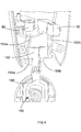
- Fig. 4 shows in close-up an exposed view of where the main body portion 120 of the steam cleaning apparatus 100 connects with the steam cleaning head 60 thereof.
- the universal joint 140 includes a member 150 which acts upon a spring-loaded yoke 152.
- One arm 152a of yoke 152 engages with pressure release valve 80 and another arm 152b of yoke 152 engages with a position-sensitive microswitch 90.
- Microswitch 90 is connected in electrical series with main on-off switch 70 of steam cleaning apparatus 100.
- yoke 152 At the other end of yoke 152 are two prongs 154a, 154b, on each of which is mounted a respective coiled spring (not shown), each such spring also being mounted to an interior surface of the main body 120 of the steam cleaning apparatus 100.
- member 150 of universal joint 140 pushes on spring-loaded yoke 152, one arm 152a of which in turn presses on pressure release valve 80 and the other arm 152b of which in turn presses on the position-sensitive microswitch 90.
- both the main on-off switch 70 and the pressure release valve 80 are affected by whether the steam cleaning apparatus is put in a substantially vertical, storage position or in a tilted, cleaning position, alternative embodiments in which only one or neither of these features are present are also possible. However, both are preferred as safety features, as well as providing increased convenience for the user.
- an additional feature of the described embodiment is an indicator light connected in series with the main on-off switch 70 of the apparatus.
- this indicator light is mounted within the interior of main body portion 120 of the apparatus, but water tank 10 is made of a translucent plastics material, so that light from the indicator light is able to shine through the water tank 10 and thus be visible by a user from the exterior of the apparatus as an apparent illumination of water tank 10.
- the indicator light has a first colour for indicating when the steam cleaning apparatus 100 is powered on but is not ready to use and a second colour for indicating when the steam cleaning apparatus 100 is powered on and is ready to use.
- the indicator light has a first condition associated with the first colour, a second condition associated with the second colour and a third condition not associated with either the first or the second colour.
- first, second and third conditions of the indicator light are achieved by electrical wiring of the indicator light in the appropriate fashion, as follows.
- the first condition of the indicator light is induced by the on-off switch 70 being put in the "on” state by a user and either the air pump 30 being prevented from receiving a supply of electrical power by the time delay circuit or the thermostat detecting that the temperature of steam generated by the boiler 30 is outside the operating temperature range.
- the second condition is induced by the on-off switch 70 being in the "on” state and the air pump 30 receiving a supply of electrical power unhindered by the time delay circuit and the thermostat detecting that the temperature of steam generated by the boiler 30 is within the desired operating temperature range.
- the third condition is induced by the on-off switch 70 being in the "off' state thereof.
- red is the first colour of the indicator light and blue is the second colour.
- any other colours could be chosen instead as the first and second colours, for example yellow and green respectively.
- the first condition of the indicator light is induced by the on-off switch 70 being put in the "on” state by a user and the air pump 30 being prevented from receiving a supply of electrical power by the time delay circuit
- the second condition is induced by the on-off switch 70 being in the "on” state and the air pump 30 receiving a supply of electrical power unhindered by the time delay circuit.
- the first condition of the indicator light is instead induced by the on-off switch 70 being put in the "on” state by a user and the thermostat detecting that the temperature of steam generated by the boiler 30 is outside the operating temperature range, whereas the second condition is induced by the on-off switch 70 being in the "on” state and the thermostat detecting that the temperature of steam generated by the boiler 30 is within the desired operating temperature range.
- the third condition of the indicator light is always induced by the on-off switch 70 being put in the "off” state by the user.
Landscapes
- Engineering & Computer Science (AREA)
- Life Sciences & Earth Sciences (AREA)
- Sustainable Development (AREA)
- Sustainable Energy (AREA)
- Physics & Mathematics (AREA)
- Thermal Sciences (AREA)
- Mechanical Engineering (AREA)
- General Engineering & Computer Science (AREA)
- Cleaning By Liquid Or Steam (AREA)
Priority Applications (1)
| Application Number | Priority Date | Filing Date | Title |
|---|---|---|---|
| EP14154676.2A EP2737838B1 (de) | 2011-03-01 | 2012-02-20 | Dampfreinigungsvorrichtung |
Applications Claiming Priority (1)
| Application Number | Priority Date | Filing Date | Title |
|---|---|---|---|
| GBGB1103604.3A GB201103604D0 (en) | 2011-03-01 | 2011-03-01 | Steam cleaning apparatus |
Related Child Applications (2)
| Application Number | Title | Priority Date | Filing Date |
|---|---|---|---|
| EP14154676.2A Division EP2737838B1 (de) | 2011-03-01 | 2012-02-20 | Dampfreinigungsvorrichtung |
| EP14154676.2A Division-Into EP2737838B1 (de) | 2011-03-01 | 2012-02-20 | Dampfreinigungsvorrichtung |
Publications (2)
| Publication Number | Publication Date |
|---|---|
| EP2494901A2 true EP2494901A2 (de) | 2012-09-05 |
| EP2494901A3 EP2494901A3 (de) | 2014-06-11 |
Family
ID=43904477
Family Applications (2)
| Application Number | Title | Priority Date | Filing Date |
|---|---|---|---|
| EP14154676.2A Active EP2737838B1 (de) | 2011-03-01 | 2012-02-20 | Dampfreinigungsvorrichtung |
| EP12156197.1A Withdrawn EP2494901A3 (de) | 2011-03-01 | 2012-02-20 | Dampfreinigungsvorrichtung |
Family Applications Before (1)
| Application Number | Title | Priority Date | Filing Date |
|---|---|---|---|
| EP14154676.2A Active EP2737838B1 (de) | 2011-03-01 | 2012-02-20 | Dampfreinigungsvorrichtung |
Country Status (7)
| Country | Link |
|---|---|
| US (2) | US9039844B2 (de) |
| EP (2) | EP2737838B1 (de) |
| CN (2) | CN102652655A (de) |
| AU (1) | AU2012200966C1 (de) |
| CA (1) | CA2768920C (de) |
| GB (1) | GB201103604D0 (de) |
| TW (1) | TW201302143A (de) |
Cited By (13)
| Publication number | Priority date | Publication date | Assignee | Title |
|---|---|---|---|---|
| EP3009060A1 (de) | 2014-10-17 | 2016-04-20 | Black & Decker Inc. | Dampfreinigungsvorrichtung |
| EP3017882A1 (de) | 2014-11-07 | 2016-05-11 | Black & Decker, Inc. | Dampfreinigungsvorrichtung und zubehör |
| WO2016055855A3 (en) * | 2014-10-09 | 2016-06-30 | Milanese Pier Antonio | Hot cleaning system for surfaces |
| EP3040132A1 (de) | 2014-11-07 | 2016-07-06 | Black & Decker, Inc. | Dampfreinigungsvorrichtung und zubehör |
| CN105769073A (zh) * | 2016-03-21 | 2016-07-20 | 苏州韩京姬科技有限公司 | 一种电动旋转拖把 |
| CN105832258A (zh) * | 2016-06-14 | 2016-08-10 | 南安市天鸿电子科技有限公司 | 感应电机升降两用扫帚 |
| CN105832259A (zh) * | 2016-06-14 | 2016-08-10 | 南安市天鸿电子科技有限公司 | 转轮控制电机升降两用拖把 |
| CN105852748A (zh) * | 2016-06-14 | 2016-08-17 | 南安市天鸿电子科技有限公司 | 一种感应电机升降两用拖把的控制方法 |
| CN105877637A (zh) * | 2016-06-14 | 2016-08-24 | 南安市天鸿电子科技有限公司 | 一种电机升降两用扫帚的控制方法 |
| CN105902242A (zh) * | 2016-06-14 | 2016-08-31 | 南安市天鸿电子科技有限公司 | 感应电机升降两用拖把 |
| CN105996919A (zh) * | 2016-06-14 | 2016-10-12 | 南安市天鸿电子科技有限公司 | 一种感应电机升降两用扫帚发控制方法 |
| ITUB20152195A1 (it) * | 2015-07-15 | 2017-01-15 | Tenacta Group Spa | Dispositivo a vapore per pulire i pavimenti |
| GB2541113A (en) * | 2016-07-08 | 2017-02-08 | Tenacta Group Spa | Floor cleaning steam device |
Families Citing this family (29)
| Publication number | Priority date | Publication date | Assignee | Title |
|---|---|---|---|---|
| US10821459B2 (en) * | 2013-10-18 | 2020-11-03 | Bissell Inc. | Apparatus for cleaning a surface |
| CN104146654B (zh) * | 2014-08-08 | 2016-05-04 | 南京九致信息科技有限公司 | 一种用于清洗幕墙玻璃的工具 |
| USD793014S1 (en) * | 2015-06-11 | 2017-07-25 | Samsung Electronics Co., Ltd. | Vacuum cleaner |
| USD792668S1 (en) * | 2015-06-11 | 2017-07-18 | Samsung Electronics Co., Ltd. | Vacuum cleaner |
| CN105167719B (zh) * | 2015-08-18 | 2017-11-28 | 东保集团有限公司 | 一种蒸汽切断回路以及蒸汽地拖 |
| WO2017101256A1 (zh) * | 2015-12-14 | 2017-06-22 | 美的集团股份有限公司 | 蒸汽发生器系统及控制方法、家用电器 |
| USD796756S1 (en) * | 2016-05-26 | 2017-09-05 | Sharkninja Operating Llc | Steam apparatus |
| CN108392148B (zh) * | 2017-02-08 | 2023-06-27 | 智意(中山)科技有限公司 | 水箱结构及智能扫地机 |
| KR102014140B1 (ko) | 2017-08-07 | 2019-08-26 | 엘지전자 주식회사 | 청소기 |
| KR102024089B1 (ko) * | 2017-08-07 | 2019-09-23 | 엘지전자 주식회사 | 로봇 청소기 |
| KR102014142B1 (ko) | 2017-08-07 | 2019-08-26 | 엘지전자 주식회사 | 로봇 청소기 |
| KR102021828B1 (ko) | 2017-08-07 | 2019-09-17 | 엘지전자 주식회사 | 청소기 |
| KR102011827B1 (ko) | 2017-08-07 | 2019-08-19 | 엘지전자 주식회사 | 로봇청소기 및 그 제어방법 |
| KR102000068B1 (ko) | 2017-08-07 | 2019-07-15 | 엘지전자 주식회사 | 청소기 |
| KR102014141B1 (ko) | 2017-08-07 | 2019-10-21 | 엘지전자 주식회사 | 로봇청소기 |
| KR102033936B1 (ko) | 2017-08-07 | 2019-10-18 | 엘지전자 주식회사 | 로봇청소기 |
| PL3488755T5 (pl) * | 2017-11-24 | 2026-02-23 | Carl Freudenberg Kg | Urządzenie czyszczące |
| KR102045003B1 (ko) | 2018-01-25 | 2019-11-14 | 엘지전자 주식회사 | 로봇청소기의 제어방법 |
| US20200060503A1 (en) | 2018-08-27 | 2020-02-27 | Tti (Macao Commercial Offshore) Limited | Floor cleaner |
| CA191619S (en) * | 2019-06-04 | 2022-03-31 | Freudenberg Carl Kg | Floorwasher - floor cleaner |
| US11172801B2 (en) | 2020-01-06 | 2021-11-16 | Techtronic Cordless Gp | Full recovery tank shutoff |
| CN111549511A (zh) * | 2020-04-30 | 2020-08-18 | 佛山市顺德区美的电热电器制造有限公司 | 蒸汽发生系统和蒸汽设备 |
| CN112603211B (zh) * | 2020-11-19 | 2022-09-13 | 江苏美的清洁电器股份有限公司 | 蒸汽清洁器及清洁系统 |
| CN112754378B (zh) * | 2021-01-29 | 2025-06-20 | 广东天物新材料科技有限公司 | 一种连接结构及包含该连接结构的蒸汽地拖 |
| CN113057518A (zh) * | 2021-03-19 | 2021-07-02 | 台山市捷达电器有限公司 | 具有双涡轮风扇的吸尘器 |
| CN113057519A (zh) * | 2021-03-19 | 2021-07-02 | 台山市捷达电器有限公司 | 具有双涡轮风扇通风装置的吸尘器 |
| CN113413099A (zh) * | 2021-06-28 | 2021-09-21 | 东莞市商斯迈智能科技有限公司 | 洗地机 |
| USD1038564S1 (en) * | 2022-03-09 | 2024-08-06 | Thane Ip Limited | Steam mop |
| USD1058978S1 (en) * | 2024-09-10 | 2025-01-21 | Yuyao Mobadi Electrical Appliance | Steam mop |
Citations (3)
| Publication number | Priority date | Publication date | Assignee | Title |
|---|---|---|---|---|
| US20070130719A1 (en) | 2005-12-10 | 2007-06-14 | Xiao Tian (Zhongshan) Industrial Co., Ltd. | Steam floor mop |
| WO2010017657A1 (zh) | 2008-08-14 | 2010-02-18 | Tsai Sam | 蒸汽拖把 |
| US20100126533A1 (en) | 2008-06-02 | 2010-05-27 | Innovation Direct Llc | Steam mop |
Family Cites Families (10)
| Publication number | Priority date | Publication date | Assignee | Title |
|---|---|---|---|---|
| CA2123740C (en) * | 1993-05-19 | 2002-12-17 | Hee-Gwon Chae | Electric vacuum cleaner |
| JPH10174669A (ja) * | 1996-12-16 | 1998-06-30 | Masahito Tashiro | 蒸気を用いたクリーニング装置 |
| US5915071A (en) * | 1997-02-18 | 1999-06-22 | National Sanitizer Inc. | Steam cleaning apparatus |
| KR20030078508A (ko) * | 2002-03-30 | 2003-10-08 | 정병기 | 자동세척 기능을 갖는 스팀진공청소기와 이를 이용한스팀발생 및 자동세척방법 |
| DE20302630U1 (de) * | 2003-02-18 | 2003-04-30 | Hsu, Bill, Shinjuang, Taipeh | Dampfschrubbmaschine |
| EP2491840A2 (de) * | 2006-09-11 | 2012-08-29 | Panasonic Corporation | Elektrischer Reiniger |
| CN201127588Y (zh) * | 2007-12-18 | 2008-10-08 | 韩军 | 蒸汽拖把 |
| US8052342B2 (en) * | 2008-05-09 | 2011-11-08 | Euro-Pro Operating Llc | Universal connector for a fluid mop |
| US8402597B2 (en) * | 2008-11-13 | 2013-03-26 | Euro-Pro Operating Llc | Steam appliance with motion switch |
| US8528161B2 (en) * | 2009-08-07 | 2013-09-10 | Euro-Pro Operating Llc | Cleaning appliance having multiple functions |
-
2011
- 2011-03-01 GB GBGB1103604.3A patent/GB201103604D0/en not_active Ceased
-
2012
- 2012-02-20 EP EP14154676.2A patent/EP2737838B1/de active Active
- 2012-02-20 AU AU2012200966A patent/AU2012200966C1/en not_active Ceased
- 2012-02-20 EP EP12156197.1A patent/EP2494901A3/de not_active Withdrawn
- 2012-02-21 CA CA2768920A patent/CA2768920C/en not_active Expired - Fee Related
- 2012-02-27 US US13/405,593 patent/US9039844B2/en active Active
- 2012-03-01 CN CN201210052301XA patent/CN102652655A/zh active Pending
- 2012-03-01 CN CN201410246740.3A patent/CN103989446B/zh not_active Expired - Fee Related
- 2012-03-01 TW TW101106796A patent/TW201302143A/zh unknown
-
2015
- 2015-05-01 US US14/701,877 patent/US9717390B2/en active Active
Patent Citations (3)
| Publication number | Priority date | Publication date | Assignee | Title |
|---|---|---|---|---|
| US20070130719A1 (en) | 2005-12-10 | 2007-06-14 | Xiao Tian (Zhongshan) Industrial Co., Ltd. | Steam floor mop |
| US20100126533A1 (en) | 2008-06-02 | 2010-05-27 | Innovation Direct Llc | Steam mop |
| WO2010017657A1 (zh) | 2008-08-14 | 2010-02-18 | Tsai Sam | 蒸汽拖把 |
Cited By (21)
| Publication number | Priority date | Publication date | Assignee | Title |
|---|---|---|---|---|
| WO2016055855A3 (en) * | 2014-10-09 | 2016-06-30 | Milanese Pier Antonio | Hot cleaning system for surfaces |
| EP3009060A1 (de) | 2014-10-17 | 2016-04-20 | Black & Decker Inc. | Dampfreinigungsvorrichtung |
| EP3017882A1 (de) | 2014-11-07 | 2016-05-11 | Black & Decker, Inc. | Dampfreinigungsvorrichtung und zubehör |
| EP3017880A1 (de) | 2014-11-07 | 2016-05-11 | Black & Decker Inc. | Dampfreinigungsvorrichtung und Zubehör |
| EP3017881A1 (de) | 2014-11-07 | 2016-05-11 | Black & Decker Inc. | Dampfreinigungsvorrichtung und zubehör |
| EP3017883A1 (de) | 2014-11-07 | 2016-05-11 | Black & Decker, Inc. | Dampfreinigungsvorrichtung und zubehör |
| EP3017884A1 (de) | 2014-11-07 | 2016-05-11 | Black & Decker, Inc. | Dampfreinigungsvorrichtung und zubehör |
| EP3040132A1 (de) | 2014-11-07 | 2016-07-06 | Black & Decker, Inc. | Dampfreinigungsvorrichtung und zubehör |
| US10278560B2 (en) | 2014-11-07 | 2019-05-07 | Black & Decker, Inc. | Steam cleaning device and accessory |
| US9861244B2 (en) | 2014-11-07 | 2018-01-09 | Black & Decker Inc. | Steam cleaning device and accessory |
| US9549652B2 (en) | 2014-11-07 | 2017-01-24 | Black & Decker Inc. | Steam cleaning device and accessory |
| US9549651B2 (en) | 2014-11-07 | 2017-01-24 | Black & Decker Inc. | Steam cleaning device and accessory |
| ITUB20152195A1 (it) * | 2015-07-15 | 2017-01-15 | Tenacta Group Spa | Dispositivo a vapore per pulire i pavimenti |
| CN105769073A (zh) * | 2016-03-21 | 2016-07-20 | 苏州韩京姬科技有限公司 | 一种电动旋转拖把 |
| CN105902242A (zh) * | 2016-06-14 | 2016-08-31 | 南安市天鸿电子科技有限公司 | 感应电机升降两用拖把 |
| CN105996919A (zh) * | 2016-06-14 | 2016-10-12 | 南安市天鸿电子科技有限公司 | 一种感应电机升降两用扫帚发控制方法 |
| CN105877637A (zh) * | 2016-06-14 | 2016-08-24 | 南安市天鸿电子科技有限公司 | 一种电机升降两用扫帚的控制方法 |
| CN105852748A (zh) * | 2016-06-14 | 2016-08-17 | 南安市天鸿电子科技有限公司 | 一种感应电机升降两用拖把的控制方法 |
| CN105832259A (zh) * | 2016-06-14 | 2016-08-10 | 南安市天鸿电子科技有限公司 | 转轮控制电机升降两用拖把 |
| CN105832258A (zh) * | 2016-06-14 | 2016-08-10 | 南安市天鸿电子科技有限公司 | 感应电机升降两用扫帚 |
| GB2541113A (en) * | 2016-07-08 | 2017-02-08 | Tenacta Group Spa | Floor cleaning steam device |
Also Published As
| Publication number | Publication date |
|---|---|
| CN103989446B (zh) | 2017-04-12 |
| CN102652655A (zh) | 2012-09-05 |
| CA2768920A1 (en) | 2012-09-01 |
| CN103989446A (zh) | 2014-08-20 |
| EP2737838A1 (de) | 2014-06-04 |
| AU2012200966C1 (en) | 2016-09-01 |
| US9717390B2 (en) | 2017-08-01 |
| TW201302143A (zh) | 2013-01-16 |
| GB201103604D0 (en) | 2011-04-13 |
| EP2494901A3 (de) | 2014-06-11 |
| US9039844B2 (en) | 2015-05-26 |
| US20120222706A1 (en) | 2012-09-06 |
| US20150230683A1 (en) | 2015-08-20 |
| AU2012200966A1 (en) | 2012-09-20 |
| CA2768920C (en) | 2016-07-19 |
| AU2012200966B2 (en) | 2016-05-12 |
| EP2737838B1 (de) | 2020-07-29 |
Similar Documents
| Publication | Publication Date | Title |
|---|---|---|
| CA2768920C (en) | Steam cleaning apparatus | |
| EP4205622A1 (de) | Oberflächenreinigungsvorrichtung mit dampfzufuhr | |
| EP4241645B1 (de) | Oberflächenreinigungsvorrichtung mit dampfzufuhr | |
| EP0672377B1 (de) | Haushaltsdampfreinigungsgerät | |
| AU2014101572A4 (en) | Surface cleaning apparatus | |
| CN209789500U (zh) | 蒸汽蒸煮器附件及包括该蒸汽蒸煮器附件的电蒸汽蒸煮器 | |
| EP3390709B1 (de) | Dampfbügeleisen mit druckbeaufschlagtem wasserbehälter | |
| CN105520696A (zh) | 蒸汽清洁装置 | |
| EP3325706B1 (de) | Bügeltisch mit dampffreisetzendem brett für den haushaltsgebrauch mit verschiedenen bügelbetriebsarten | |
| EP3263236B1 (de) | Dampfreinigungsvorrichtung | |
| AU2015323596A1 (en) | Surface cleaning apparatus | |
| GB2232068A (en) | Cleaning apparatus | |
| CA2596707A1 (en) | Steam cleaner and steam iron apparatus | |
| GB2545725A (en) | A steam cleaner | |
| KR101272672B1 (ko) | 포트 장착형 정수기 | |
| JP6762902B2 (ja) | スチーマ | |
| JP2001204996A (ja) | アイロン |
Legal Events
| Date | Code | Title | Description |
|---|---|---|---|
| PUAI | Public reference made under article 153(3) epc to a published international application that has entered the european phase |
Free format text: ORIGINAL CODE: 0009012 |
|
| AK | Designated contracting states |
Kind code of ref document: A2 Designated state(s): AL AT BE BG CH CY CZ DE DK EE ES FI FR GB GR HR HU IE IS IT LI LT LU LV MC MK MT NL NO PL PT RO RS SE SI SK SM TR |
|
| AX | Request for extension of the european patent |
Extension state: BA ME |
|
| PUAL | Search report despatched |
Free format text: ORIGINAL CODE: 0009013 |
|
| AK | Designated contracting states |
Kind code of ref document: A3 Designated state(s): AL AT BE BG CH CY CZ DE DK EE ES FI FR GB GR HR HU IE IS IT LI LT LU LV MC MK MT NL NO PL PT RO RS SE SI SK SM TR |
|
| AX | Request for extension of the european patent |
Extension state: BA ME |
|
| RIC1 | Information provided on ipc code assigned before grant |
Ipc: A47L 11/40 20060101ALI20140506BHEP Ipc: A47L 13/22 20060101AFI20140506BHEP |
|
| STAA | Information on the status of an ep patent application or granted ep patent |
Free format text: STATUS: THE APPLICATION IS DEEMED TO BE WITHDRAWN |
|
| 18D | Application deemed to be withdrawn |
Effective date: 20141212 |