EP2495510A1 - Wärmepumpe - Google Patents
Wärmepumpe Download PDFInfo
- Publication number
- EP2495510A1 EP2495510A1 EP09850811A EP09850811A EP2495510A1 EP 2495510 A1 EP2495510 A1 EP 2495510A1 EP 09850811 A EP09850811 A EP 09850811A EP 09850811 A EP09850811 A EP 09850811A EP 2495510 A1 EP2495510 A1 EP 2495510A1
- Authority
- EP
- European Patent Office
- Prior art keywords
- refrigerant
- heat
- radiator
- heat exchanger
- water
- Prior art date
- Legal status (The legal status is an assumption and is not a legal conclusion. Google has not performed a legal analysis and makes no representation as to the accuracy of the status listed.)
- Granted
Links
Images





Classifications
-
- F—MECHANICAL ENGINEERING; LIGHTING; HEATING; WEAPONS; BLASTING
- F25—REFRIGERATION OR COOLING; COMBINED HEATING AND REFRIGERATION SYSTEMS; HEAT PUMP SYSTEMS; MANUFACTURE OR STORAGE OF ICE; LIQUEFACTION SOLIDIFICATION OF GASES
- F25B—REFRIGERATION MACHINES, PLANTS OR SYSTEMS; COMBINED HEATING AND REFRIGERATION SYSTEMS; HEAT PUMP SYSTEMS
- F25B30/00—Heat pumps
- F25B30/02—Heat pumps of the compression type
-
- F—MECHANICAL ENGINEERING; LIGHTING; HEATING; WEAPONS; BLASTING
- F25—REFRIGERATION OR COOLING; COMBINED HEATING AND REFRIGERATION SYSTEMS; HEAT PUMP SYSTEMS; MANUFACTURE OR STORAGE OF ICE; LIQUEFACTION SOLIDIFICATION OF GASES
- F25B—REFRIGERATION MACHINES, PLANTS OR SYSTEMS; COMBINED HEATING AND REFRIGERATION SYSTEMS; HEAT PUMP SYSTEMS
- F25B13/00—Compression machines, plants or systems, with reversible cycle
-
- F—MECHANICAL ENGINEERING; LIGHTING; HEATING; WEAPONS; BLASTING
- F25—REFRIGERATION OR COOLING; COMBINED HEATING AND REFRIGERATION SYSTEMS; HEAT PUMP SYSTEMS; MANUFACTURE OR STORAGE OF ICE; LIQUEFACTION SOLIDIFICATION OF GASES
- F25B—REFRIGERATION MACHINES, PLANTS OR SYSTEMS; COMBINED HEATING AND REFRIGERATION SYSTEMS; HEAT PUMP SYSTEMS
- F25B6/00—Compression machines, plants or systems, with several condenser circuits
- F25B6/04—Compression machines, plants or systems, with several condenser circuits arranged in series
-
- F—MECHANICAL ENGINEERING; LIGHTING; HEATING; WEAPONS; BLASTING
- F25—REFRIGERATION OR COOLING; COMBINED HEATING AND REFRIGERATION SYSTEMS; HEAT PUMP SYSTEMS; MANUFACTURE OR STORAGE OF ICE; LIQUEFACTION SOLIDIFICATION OF GASES
- F25B—REFRIGERATION MACHINES, PLANTS OR SYSTEMS; COMBINED HEATING AND REFRIGERATION SYSTEMS; HEAT PUMP SYSTEMS
- F25B2313/00—Compression machines, plants or systems with reversible cycle not otherwise provided for
- F25B2313/023—Compression machines, plants or systems with reversible cycle not otherwise provided for using multiple indoor units
- F25B2313/0233—Compression machines, plants or systems with reversible cycle not otherwise provided for using multiple indoor units in parallel arrangements
-
- F—MECHANICAL ENGINEERING; LIGHTING; HEATING; WEAPONS; BLASTING
- F25—REFRIGERATION OR COOLING; COMBINED HEATING AND REFRIGERATION SYSTEMS; HEAT PUMP SYSTEMS; MANUFACTURE OR STORAGE OF ICE; LIQUEFACTION SOLIDIFICATION OF GASES
- F25B—REFRIGERATION MACHINES, PLANTS OR SYSTEMS; COMBINED HEATING AND REFRIGERATION SYSTEMS; HEAT PUMP SYSTEMS
- F25B2339/00—Details of evaporators; Details of condensers
- F25B2339/04—Details of condensers
- F25B2339/047—Water-cooled condensers
-
- F—MECHANICAL ENGINEERING; LIGHTING; HEATING; WEAPONS; BLASTING
- F25—REFRIGERATION OR COOLING; COMBINED HEATING AND REFRIGERATION SYSTEMS; HEAT PUMP SYSTEMS; MANUFACTURE OR STORAGE OF ICE; LIQUEFACTION SOLIDIFICATION OF GASES
- F25B—REFRIGERATION MACHINES, PLANTS OR SYSTEMS; COMBINED HEATING AND REFRIGERATION SYSTEMS; HEAT PUMP SYSTEMS
- F25B2400/00—Component parts or details not otherwise provided for in this subclass
- F25B2400/05—Compression system with heat exchange between particular parts of the system
-
- F—MECHANICAL ENGINEERING; LIGHTING; HEATING; WEAPONS; BLASTING
- F25—REFRIGERATION OR COOLING; COMBINED HEATING AND REFRIGERATION SYSTEMS; HEAT PUMP SYSTEMS; MANUFACTURE OR STORAGE OF ICE; LIQUEFACTION SOLIDIFICATION OF GASES
- F25B—REFRIGERATION MACHINES, PLANTS OR SYSTEMS; COMBINED HEATING AND REFRIGERATION SYSTEMS; HEAT PUMP SYSTEMS
- F25B25/00—Machines, plants or systems, using a combination of modes of operation covered by two or more of the groups F25B1/00 - F25B23/00
- F25B25/005—Machines, plants or systems, using a combination of modes of operation covered by two or more of the groups F25B1/00 - F25B23/00 using primary and secondary systems
-
- F—MECHANICAL ENGINEERING; LIGHTING; HEATING; WEAPONS; BLASTING
- F25—REFRIGERATION OR COOLING; COMBINED HEATING AND REFRIGERATION SYSTEMS; HEAT PUMP SYSTEMS; MANUFACTURE OR STORAGE OF ICE; LIQUEFACTION SOLIDIFICATION OF GASES
- F25B—REFRIGERATION MACHINES, PLANTS OR SYSTEMS; COMBINED HEATING AND REFRIGERATION SYSTEMS; HEAT PUMP SYSTEMS
- F25B7/00—Compression machines, plants or systems, with cascade operation, i.e. with two or more circuits, the heat from the condenser of one circuit being absorbed by the evaporator of the next circuit
Definitions
- the present invention relates to a heat pump including a compressor, a plurality of radiators, an expansion valve, and an evaporator.
- Patent Literature 1 a heat pump including a primary-side refrigerant circuit in which a compressor, a plurality of gas coolers, an expansion valve, and an evaporator are connected by refrigerant piping, and a secondary-side refrigerant circuit in which a gas cooler and a circulation pump are connected by piping is proposed.
- this heat pump water flowing through the secondary-side refrigerant circuit is heated in the gas cooler, and the heated water is used in hot water supply, cooling and heating, floor heating, and the like.
- a method for connecting (serial connection and parallel connection) the gas coolers in accordance with the influx temperature of water flowing into the gas coolers is proposed.
- the gas coolers are disposed based on a connection method in accordance with the influx temperature of water flowing into the gas coolers, and COP is improved by utilizing the heat energy of a refrigerant flowing through the gas coolers in a cascaded manner.
- Patent Literature 2 a heat pump that performs refrigeration and freezing in which a high order-side refrigeration system, which assists the heat transfer of a low order-side refrigeration system, is connected to a radiator outlet of the low order-side refrigeration system is proposed.
- a cooling operation such as refrigeration or freezing
- refrigerant in an outlet of an outdoor heat exchanger is cooled using the high order-side refrigeration system in order to improve the refrigeration capacity.
- the present invention has been made to overcome the above-described problems, and an object of the invention is to provide a heat pump capable of operating in a high COP state even if the influx temperature of a medium to be heated, which is used in heating or hot water supply or the like, flowing into the radiators has risen.
- a heat pump includes a first compressor, a plurality of radiators, a first pressure reducing device, and an evaporator being connected by refrigerant piping to form a first refrigeration cycle in which a first refrigerant circulates.
- the radiators are serially connected and when viewed along a direction of flow of the first refrigerant, a first heat exchange unit that heats the first refrigerant is provided in a refrigerant piping on a refrigerant inlet side of at least one of the second and subsequent radiators and a second heat exchange unit that cools the first refrigerant is provided in a refrigerant piping on a refrigerant outlet side of a radiator that is disposed at the most upstream position among the radiator(s) that is provided with a first heat exchange unit, or of a radiator that is further downstream of the radiator that is provided with a first heat exchange unit and that is disposed at the most upstream position.
- a first heat exchange unit that heats the first refrigerant is provided in a refrigerant piping on a refrigerant inlet side of at least one of the second and subsequent radiators when viewed along a direction of flow of the first refrigerant. Therefore, even if the influx temperature of a medium to be heated, which is used in heating or hot water supply or the like, flowing into the radiators has increased, a temperature difference between the medium to be heated and the first refrigerant can be maintained in the second and subsequent radiators.
- a second heat exchange unit that cools the first refrigerant is provided in a refrigerant piping on a refrigerant outlet side of a radiator that is disposed at the most upstream position among the radiator(s) that is provided with a first heat exchange unit, or of a radiator that is further downstream of the radiator that is provided with a first heat exchange unit and that is disposed at the most upstream position. Therefore, an enthalpy difference of the first refrigerant flowing through the evaporator can be increased.
- the heat collecting capacity of the evaporator can be improved, and the efficiency (heating capacity) of the heat pump can be improved. Accordingly, a heat pump can be obtained that is capable of operating in a high COP state even if the temperature of the medium to be heated, which is used in heating or hot water supply or the like, flowing into the radiator has increased.
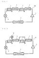
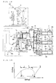
- Fig. 1 is a refrigerant circuit diagram showing an example of the heat pump according to Embodiment 1.
- a "heat pump” refers to a refrigeration device that performs hot water supply and air conditioning.
- a heat pump 100 a first compressor 1, a first radiator 2, a second radiator 4, an expansion valve 6, and an evaporator 7 are connected by refrigerant piping to form a primary-side refrigeration cycle.
- the heat pump 100 is used for, for example, heating, and air (the first radiator 2 and the second radiator 4) supplied by a fan or the like (not illustrated) is heated by a primary-side refrigerant that flows through the first radiator 2 and the second radiator 4.
- Embodiment 1 as the primary-side refrigerant, a refrigerant (for example, carbon dioxide) that operates in a supercritical state in the course of radiation is used.
- the expansion valve 6 corresponds to a first pressure reducing device of the invention, and the primary-side refrigeration cycle corresponds to a first refrigeration cycle of the invention.
- the primary-side refrigerant corresponds to a first refrigerant of the invention.
- the first pressure reducing device is not limited to the expansion valve 6, and various devices can be used. For example, a capillary or the like can be used as the first pressure reducing device.
- a first heat exchange unit 3 is provided in an upstream piping of the second radiator 4.
- the first heat exchange unit 3 heats the primary-side refrigerant flowing through the primary-side refrigeration cycle.
- a second heat exchange unit 5 is provided in a downstream piping of the second radiator 4. The second heat exchange unit 5 cools the primary-side refrigerant flowing through the primary-side refrigeration cycle.
- Fig. 1 describes an example using two radiators (the first radiator 2 and the second radiator 4), any number of radiators can be provided as long as a plurality (two or more) of radiators are serially connected.
- a first heat exchange unit 3 may be provided in an upstream piping (refrigerant inlet-side piping) of at least one radiator among the second and subsequent radiators along a direction of flow of the primary-side refrigerant.
- the second radiator 4 may be provided in a downstream piping (refrigerant outlet-side piping) of a radiator that is provided with a first heat exchange unit and that is disposed at the most upstream position among the radiator(s) that is provided with a first heat exchange unit 3, or of a radiator that is further downstream of the radiator that is provided with a first heat exchange unit 3 and that is disposed at the most upstream position.
- the second heat exchange unit 5 should ideally be provided in a downstream piping of a radiator disposed at the most downstream position, because there are cases in which the primary-side refrigerant that has flowed out of an intermediate radiator need to be cooled in the second heat exchange unit 5 when, for example, there is a spaced interval between the radiators or the like.
- the plurality of radiators are not limited to an air heat exchanger that exchanges heat with air, and a water heat exchanger that exchanges heat with water or brine or the like (hereinafter, when it is not particularly necessary to make a distinction between water or brine or the like, the term "water” alone will be used) may be used. Both air heat exchangers and water heat exchangers may of course be provided in the primary-side refrigeration cycle.
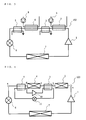
- Fig. 2 is a refrigerant circuit diagram showing another example of the heat pump according to Embodiment 1.
- Water is serially supplied to the first radiator 2 and the second radiator 4 through a pump 8.
- the flow direction of the primary-side refrigerant and the flow direction of the water counter each other.
- the water heated in the first radiator 2 and the second radiator 4 is used for, for example, hot water supply. Further, for example, the water heated in the first radiator 2 and the second radiator 4 flows into an indoor unit, a panel heater, a radiator, or the like connected to a water circuit to be used for heating and floor heating.
- first radiator 2 and the second radiator 4 water heat exchangers
- a water plate heat exchanger As the first radiator 2 and the second radiator 4 (water heat exchangers), a water plate heat exchanger, a water double pipe heat exchanger, a microchannel water heat exchanger, and the like may be used.
- Fig. 3 is a refrigerant circuit diagram showing a further example of the heat pump according to Embodiment 1.
- Water used for water supply, heating, and the like is separately supplied to each of the first radiator 2 and the second radiator 4.
- water is supplied to the first radiator 2 via a pump 9, and water is supplied to the second radiator 4 via a pump 8. Water can be serially supplied in this way to the first radiator 2 and the second radiator 4.
- the first compressor 1 sucks in refrigerant evaporated in the evaporator 7 via an accumulator (not illustrated). During normal operation, the first compressor 1 compresses the primary-side refrigerant to its critical pressure or higher. Note that the accumulator does not have to be provided.
- the primary-side refrigerant compressed in the first compressor 1 flows into the first radiator 2 and exchanges heat with air or water that is supplied (made to flow in) by a fan (not illustrated) or a pump (pump 8, 9), and is thereby cooled.
- the primary-side refrigerant that has been cooled in the first radiator 2 flows into the first heat exchange unit 3 and exchanges heat with a fluid with a higher temperature than that of the primary-side refrigerant, and is thereby heated.
- the primary-side refrigerant that has been heated in the first heat exchange unit 3 flows into the second radiator 4, and exchanges heat with air or water that is supplied by a fan or a pump (pump 8), and is thereby cooled.
- the primary-side refrigerant that has been cooled in the first radiator 2 flows into the first heat exchange unit 3 and exchanges heat with a fluid of a higher temperature than that of the primary-side refrigerant, and is thereby heated.
- the primary-side refrigerant that has been heated in the first heat exchange unit 3 flows into the second heat exchange unit 5 and exchanges heat with a fluid of a lower temperature than that of the primary-side refrigerant, and is thereby cooled.
- the refrigerant that has flowed out from the second heat exchange unit 5 is decompressed in the expansion valve 6 to become a low-temperature low-pressure two-phase gas-liquid refrigerant.
- This primary-side refrigerant flows into the evaporator 7 and exchanges heat with air or water (receives heat from air or water) that flows into the evaporator.
- the primary-side refrigerant that has flowed out of the evaporator 7 is sucked into the compressor via the accumulator (not illustrated).
- the primary-side refrigerant that has been cooled in the first radiator 2 is heated in the first heat exchange unit 3 and then flows into the second radiator 4. Therefore, even if the temperature of a medium to be heated (air or water or the like) flowing into the second radiator 4 is high, the temperature difference between the medium to be heated and the primary-side refrigerant that have flowed into the second radiator 4 can be increased. Thereby, the heat exchange efficiency in the second radiator 4 can be improved.
- the temperature of the primary-side refrigerant can be decreased (for example, decreased below the temperature of the medium to be heated flowing into the second radiator 4) before it flows into the expansion valve 6. Therefore, the enthalpy difference of the primary-side refrigerant flowing through the evaporator 7 can be increased, and thereby the heat collecting capacity of the evaporator can be improved, and the efficiency (heating capacity) of the heat pumps 100 to 102 can be improved. Accordingly, a heat pump can be obtained that is capable of operating in a high COP state even if the temperature of the medium to be heated flowing into the first radiator 2 or the second radiator 4 has risen.
- a refrigerant for example, carbon dioxide
- a refrigerant that operates in a supercritical state in the course of radiation is used.
- a refrigerant that operates at or below critical pressure in the course of radiation is used in a heat pump in which radiators are serially connected, the refrigerant flowing into the radiators may enter a two-phase gas-liquid state.
- the ratio between the gas phase refrigerant and the liquid phase refrigerant for example, it is necessary to provide a distributor or the like).
- Embodiment 1 a refrigerant (for example, carbon dioxide) that operates in a supercritical state (single phase) in the course of radiation is used as the primary-side refrigerant.
- a refrigerant for example, carbon dioxide
- the primary-side refrigerant it is not necessary to consider the distribution of the refrigerant to each path (passage) of the radiators. Therefore, the flow velocity of the refrigerant flowing through the radiators can be increased, and heat exchange can be efficiently carried out.
- the heat pump according to the invention can also be constituted as below, for example. Note that in Embodiment 2, items not described in particular are the same as Embodiment 1 and like functions and configurations are described using like reference numerals.
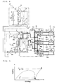
- Fig. 4 is a refrigerant circuit diagram showing an example of the heat pump according to Embodiment 2.
- the primary-side refrigeration cycle of a heat pump 103 according to Embodiment 2 has the same constitution as the primary-side refrigeration cycle of the heat pump 100 of Embodiment 1 as illustrated in Fig. 1 .
- the heat pump 103 of Embodiment 2 is different from the heat pump 100 of Embodiment 1 illustrated in Fig. 1 in that it is provided with a secondary-side refrigeration cycle that includes the first heat exchange unit 3 and the second heat exchange unit 5 as constituent elements.
- the heat pump 103 includes a secondary-side refrigeration cycle in which a second compressor 10, the first heat exchange unit 3, a second expansion valve 11, and the second heat exchange unit 5 are connected in a refrigerant circuit.
- a secondary-side refrigerant circulates in the secondary-side refrigeration cycle. In other words, the same refrigerant flows in the first heat exchange unit 3 and the second heat exchange unit 5.
- the first heat exchange unit 3 functions as a radiator and the second heat exchange unit 5 functions as an evaporator.
- the flow direction of the primary-side refrigerant and the flow direction of the secondary-side refrigerant counter each other.
- a carbon dioxide refrigerant is used as the primary-side refrigerant.
- a propane refrigerant, an HFO-1234yf refrigerant, an ammonia refrigerant, or the like is used as the secondary-side refrigerant.
- These refrigerants have a higher theoretical COP than that of a carbon dioxide refrigerant at the evaporating temperature of 10 degrees C to 30 degrees C and the psuedo-critical temperature or the condensing temperature of 30 degrees C to 50 degrees C.
- the primary-side refrigerant and the secondary-side refrigerant used in the heat pump 103 have a lower GWP than refrigerants such as an R410A refrigerant (whose GWP is approximately 2000) that is normally used in conventional heat pumps.
- refrigerants such as an R410A refrigerant (whose GWP is approximately 2000) that is normally used in conventional heat pumps.
- R410A refrigerant whose GWP is approximately 2000
- GWP global warming potential
- IPCC Intergovernmental Panel on climate Change
- the second expansion valve 11 corresponds to a second pressure reducing device of the invention
- the secondary-side refrigeration cycle corresponds to a second refrigeration cycle of the invention
- the secondary-side refrigerant corresponds to a second refrigerant of the invention.
- the second pressure reducing device is not limited to the second expansion valve 11, and various devices can be used. For example, a capillary or the like can be used as the second pressure reducing device.
- Fig. 4 describes an example using two radiators (the first radiator 2 and the second radiator 4), any number of radiators can be provided as long as a plurality (two or more) of radiators are serially connected.
- a first heat exchange unit 3 may be provided in an upstream piping (refrigerant inlet-side piping) of at least one radiator among the second and subsequent radiators along a direction of flow of the primary-side refrigerant.
- the second heat exchange unit 5 may be provided in a downstream piping (refrigerant outlet-side piping) of a radiator disposed at the most downstream position along a direction of flow of the primary-side refrigerant.
- the plurality of radiators are not limited to an air heat exchanger that exchanges heat with air, and a water heat exchanger can be used. Both air heat exchangers and water heat exchangers may of course be provided in the primary-side refrigeration cycle.
- Fig. 5 is a P-h diagram of a primary-side refrigerant when the secondary-side refrigeration cycle is not operated in the heat pump according to Embodiment 2.
- Fig. 6 is a P-h diagram of a primary-side refrigerant when the secondary-side refrigeration cycle is operated in the heat pump according to Embodiment 2.
- Points a to e shown in Figs. 5 and 6 show the state of the refrigerant at each position a to e shown in Fig. 4 .
- Figs. 5 and 6 illustrate a case in which a temperature T of the medium to be heated flowing into the second radiator 4 is T1 [degrees C].
- the primary-side refrigerant that has flowed out of the first radiator 2 flows into the second radiator 4 without being heated (b ⁇ c). Therefore, if the temperature of the medium to be heated flowing into the second radiator 4 is high, the temperature difference between the medium to be heated and the primary-side refrigerant that have flowed into the second radiator 4 becomes small.
- the temperature of the primary-side refrigerant at the outlet of the second radiator 4 need to be increased above T1 [degrees C] (d).
- the primary-side refrigerant that has flowed out of the second radiator 4 flows into the expansion valve 6 without being cooled (e). Therefore, if the temperature of the medium to be heated flowing into the second radiator 4 is high, the enthalpy difference of the primary-side refrigerant flowing through the evaporator 7 becomes small, and thus the heating capacity of the heat pump 103 decreases.
- the primary-side refrigerant that has flowed out of the first radiator 2 flows into the second radiator 4 after being heated in the first heat exchange unit (b ⁇ c). Therefore, even if the temperature of the medium to be heated flowing into the second radiator 4 is high, the temperature difference between the medium to be heated and the primary-side refrigerant that have flowed into the second radiator 4 can be increased.
- the primary-side refrigerant that has flowed out of the second radiator 4 flows into the expansion valve 6 after being cooled in the second heat exchange unit 5 (d ⁇ e).
- the temperature of the primary-side refrigerant flowing into the expansion valve 6 can be decreased below T1 [degrees C].
- T1 degrees C
- the enthalpy difference of the primary-side refrigerant flowing through the evaporator 7 can be increased, and the heating capacity of the heat pump 103 can be improved.
- the same refrigerant (the secondary-side refrigerant) flows in the first heat exchange unit 3 and the second heat exchange unit 5.
- heat collected from the primary-side refrigerant in the second heat exchange unit 5 can be used for heating of the primary-side refrigerant in the first heat exchange unit 3.
- the heating efficiency of the heat pump 103 can be further improved.
- This effect is large when using a refrigerant whose specific heat of liquid is large in a supercritical state, such as a carbon dioxide refrigerant, as the primary-side refrigerant.
- This kind of primary-side refrigerant has a large specific heat when heated between b ⁇ c, and thus the secondary-side refrigeration cycle can be operated in a state of high operating efficiency.
- the temperature of the medium to be heated flowing into the radiators is 35 degrees C
- the primary-side refrigerant is carbon dioxide
- the secondary-side refrigerant is a propane refrigerant
- the heat pump 103 is operated so as to decrease the temperature of the primary-side refrigerant at the outlet of the second heat exchange unit 5 to approximately 15 degrees C to 25 degrees C.
- COP of the secondary-side refrigerant that heats the carbon dioxide refrigerant becomes about 10 (including loss due to the efficiency of the compressor for propane), and a large heating capacity can be obtained with a small amount of electrical input.
- the heating capacity over the sum of the electrical inputs of the primary-side refrigeration cycle and the secondary-side refrigeration cycle (system COP) can be increased by 10 to 20% compared to a case in which the secondary-side refrigeration cycle is not operated.
- the heat pump 103 constituted as above, if the temperature of the medium to be heated flowing into the radiators (in particular, the second radiator 4) becomes high, by operating the secondary-side refrigeration cycle, in addition to the effect of Embodiment 1, heat collected from the primary-side refrigerant in the second heat exchange unit 5 can be used for heating of the primary-side refrigerant in the first heat exchange unit 3. Thereby, the heating efficiency of the heat pump 103 can be further improved.
- the heat pump according to the invention can be used in an air conditioning apparatus like the one described below.
- air conditioning apparatus like the one described below.
- items not described in particular are the same as Embodiment 1 or Embodiment 2 and like functions and configurations are described using like reference numerals.
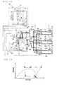
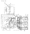
- FIG. 7 is a refrigerant circuit diagram showing an example of the heat pump according to Embodiment 3.
- a heat pump 104 according to Embodiment 3 is a multi-room air conditioning apparatus in which a heat source unit A (outdoor unit), a relay unit B, and a plurality of indoor units (indoor units C, D, and E) are connected by piping and are capable of being placed apart from each other.
- the heat source unit A can be installed on a roof of a building
- the relay unit B can be installed above a ceiling on each floor of the building
- the indoor units C, D, and E can be installed in each room.
- the heat pump 104 is an air conditioning apparatus capable of setting cooling or heating separately for each indoor unit.
- heat transport from the heat source unit A to the relay unit B and heat transport from the relay unit B to the indoor units C, D, and E are carried out using different refrigerant circuits.
- Heat transport from the heat source unit A to the relay unit B is carried out by a refrigerant such as carbon dioxide whose pressure upon discharge from a compressor 21 is higher than a critical pressure.
- Heat transport from the relay unit B to the indoor units C, D, and E is carried out by water.
- Heat transport from the relay unit B to the indoor units C, D, and E can also be carried out using brine such as antifreeze, a mixture of antifreeze and water, a mixture of water and an additive having a high anticorrosive effect, and the like.
- Embodiment 3 a case in which one relay unit and three indoor units are connected to one heat source unit will be described, but the same description applies when two or more heat source units, two or more relay units, and two or more indoor units are connected.
- the heat source unit A includes a compressor 21, a four-way switching valve 22 that switches the flow direction of the refrigerant that has been discharged from the compressor 21, a heat source side heat exchanger 23 (outdoor heat exchanger), an accumulator 24, a flow switching valve constituted by check valves 35 to 38, and the like.
- the following description will use an air-cooled heat source side heat exchanger as an example of the heat source side heat exchanger 23, but other types of heat exchangers such as a water-cooled heat exchanger can be used as long as it can exchange heat between a refrigerant and another fluid.
- the four-way switching valve 22 is connected to the discharge side, and the accumulator 24 is connected to the suction side.
- the four-way switching valve 22 is connected to the compressor 21, the heat source side heat exchanger 23, the accumulator 24, and the flow switching valve.
- the passage of refrigerant is switched between a passage in which refrigerant that has been discharged from the compressor 21 flows into the heat source side heat exchanger 23 (in other words, a passage in which refrigerant that has flowed out of the flow switching valve flows into the accumulator 24) and a passage in which refrigerant that has been discharged from the compressor 21 flows into the flow switching valve (a passage in which refrigerant that has flowed out of the heat source side heat exchanger 23 flows into the accumulator 24).
- the flow switching valve includes four check valves (check valves 35 to 38).
- the check valve 35 is provided between the heat source side heat exchanger 23 and a second connecting piping 27, and permits the flow of the refrigerant only from the heat source side heat exchanger 23 to the second connecting piping 27.
- the check valve 36 is provided between the four-way switching valve 22 of the heat source unit A and a first connecting piping 26, and permits the flow of the refrigerant only from the first connecting piping 26 to the four-way switching valve 22.
- the check valve 37 is provided between the four-way switching valve 22 of the heat source unit A and the second connecting piping 27, and permits the flow of the refrigerant only from the four-way switching valve 22 to the second connecting piping 27.
- the check valve 38 is provided between the heat source side heat exchanger 23 and the first connecting piping 26, and permits the flow of the refrigerant only from the first connecting piping 26 to the heat source side heat exchanger 23.
- the other end of the second connecting piping 27 is connected to a bypass piping 39a of the relay unit B to be described below.
- the other end of the first connecting piping 26 is connected to a first branching unit 30 of the relay unit B to be described below.
- the pipe diameter of the second connecting piping 27 can be narrower than the pipe diameter of the first connecting piping 26.
- the indoor unit C includes an indoor heat exchanger 25c.
- One end of the indoor heat exchanger 25c is connected to flow switching valves 42i and 42l of the relay unit B to be described below via a first connecting piping 26c.
- the other end of the indoor heat exchanger 25c is connected to flow switching valves 42c and 42f of the relay unit B to be described below via a second connecting piping 27c.
- a flow control device 43c is provided in the second connecting piping 27c between the indoor heat exchanger 25c and the flow switching valves 42c and 42f.
- the flow control device 43c may also be provided in the first connecting piping 26c between the indoor heat exchanger 25c and the flow switching valves 42i and 42l.
- the indoor unit D includes an indoor heat exchanger 25d.
- One end of the indoor heat exchanger 25d is connected to flow switching valves 42j and 42m of the relay unit B to be described below via a first connecting piping 26d.
- the other end of the indoor heat exchanger 25d is connected to flow switching valves 42d and 42g of the relay unit B to be described below via a second connecting piping 27d.
- a flow control device 43c is provided in the second connecting piping 27d between the indoor heat exchanger 25c and the flow switching valves 42d and 42g.
- the flow control device 43c may also be provided in the first connecting piping 26d between the indoor heat exchanger 25d and the flow switching valves 42j and 42m.
- the indoor unit E includes an indoor heat exchanger 25e.
- One end of the indoor heat exchanger 25e is connected to flow switching valves 42k and 42n of the relay unit B to be described below via a first connecting piping 26e.
- the other end of the indoor heat exchanger 25e is connected to flow switching valves 42e and 42h of the relay unit B to be described below via a second connecting piping 27e.
- a flow control device 43c is provided in the second connecting piping 27e between the indoor heat exchanger 25e and the flow switching valves 42e and 42h.
- the flow control device 43c may also be provided in the first connecting piping 26e between the indoor heat exchanger 25e and the flow switching valves 42k and 42n.
- the first connecting pipings 26c, 26d, and 26e are indoor unit-side pipings corresponding to the first connecting piping 26.
- the second connecting pipings 27c, 27d, and 27e are indoor unit-side pipings corresponding to the second connecting piping 27.
- the first connecting pipings 26c, 26d, and 26e and the second connecting pipings 27c, 27d, and 27e are pipings through which water flows.
- the density of the water flowing through the first connecting pipings 26c, 26d, and 26e is approximately the same as the density of the water flowing through the second connecting pipings 27c, 27d, and 27e. Therefore, the pipe diameter of these pipings can be the same.
- the relay unit B has a primary-side refrigeration cycle in which an intermediate heat exchangers 40 (intermediate heat exchangers 40a and 40b), first flow control devices 29a and 29b, the first branching unit 30, a second branching unit 31, a second flow control device 32, a third flow control device 33, and the like are connected by piping.
- the relay unit B also has a secondary-side refrigeration cycle in which a second compressor 50, a first heat exchange unit 51, an expansion valve 52, and a second heat exchange unit 53 are connected by piping.
- the first branching unit 30 includes solenoid valves 28a, 28b, 28c, and 28d. One end of each of the solenoid valves 28a and 28c is connected to the intermediate heat exchanger 40a. The other end of the solenoid valve 28a is connected to the second connecting piping 27. The other end of the solenoid valve 28c is connected to the first connecting piping 26. One end of each of the solenoid valves 28b and 28d is connected to the intermediate heat exchanger 40b.
- the first heat exchange unit 51 is provided in a piping connecting the solenoid valve 28b and the intermediate heat exchanger 40b. The other end of the solenoid valve 28b is connected to the second connecting piping 27. The other end of the solenoid valve 28d is connected to the first connecting piping 26.
- the second branching unit 31 is connected to the intermediate heat exchangers 40a and 40b.
- the first flow control device 29a is provided between the second branching unit 31 and the intermediate heat exchanger 40a.
- the first flow control device 29b and the second heat exchange unit 53 are provided between the second branching unit 31 and the intermediate heat exchanger 40b from the second branching unit 31 side.
- the opening degree of the first flow control device 29a is adjusted based on the degree of superheat on the outlet side of the intermediate heat exchanger 40a during cooling, and adjusted based on the degree of supercooling of the intermediate heat exchanger 40a during heating.
- the opening degree of the first flow control device 29b is adjusted based on the degree of superheat on the outlet side of the intermediate heat exchanger 40b during cooling, and adjusted based on the degree of supercooling of the intermediate heat exchanger 40b during heating.
- a solenoid valve 28e is provided so that the intermediate heat exchanger 40b is connected downstream of the intermediate heat exchanger a during heating operation.
- the second branching unit 31 is connected to the second connecting piping 27 via the first bypass piping 39a, and connected to the first connecting piping 26 via a second bypass piping 39b.
- the openable and closable second flow control device 32 is provided in the first bypass piping 39a, and the third flow control device 33 whose opening degree can be freely adjusted is provided in the second bypass piping 39b.
- An internal heat exchanger 34 that exchanges heat between the refrigerant flowing through the first bypass piping 39a and the refrigerant flowing through the second bypass piping 39b is provided in the first bypass piping 39a and the second bypass piping 39b.
- the internal heat exchanger 34 does not have to be provided.
- the second compressor 50, the first heat exchange unit 51, the expansion valve 52, and the second heat exchange unit 53 are connected by piping to form the secondary-side refrigeration cycle.
- the flow direction of the primary-side refrigerant flowing through the primary-side refrigeration cycle and the flow direction of the secondary-side refrigerant flowing through the secondary-side refrigeration cycle counter each other.
- the intermediate heat exchangers 40a and 40b exchange heat between the primary-side refrigerant and the water that transports heat to the indoor units C, D, and E.
- the intermediate heat exchangers 40a and 40b can be, for example, a water plate heat exchanger, a water double pipe heat exchanger, a microchannel water heat exchanger, and the like.
- the intermediate heat exchanger 40a is provided in the middle of a water circuit in which the water that transports heat to the indoor units C, D, and E circulates.
- One end of this water circuit is connected to the flow switching valves 42c, 42d, and 42e.
- the other end of this water circuit is connected to the flow switching valves 42i, 42j, and 42k.
- a pump 41 a that circulates the water within the water circuit is provided to this water circuit.
- the intermediate heat exchanger 40b is provided in the middle of a water circuit in which the water that transports heat to the indoor units C, D, and E circulates.
- One end of this water circuit is connected to the flow switching valves 42f, 42g, and 42h.
- the other end of this water circuit is connected to the flow switching valves 42l, 42m, and 42n.
- a pump 41 b that circulates the water within the water circuit is provided to this water circuit.
- the operations of the heat pump 104 include the following four modes in accordance with the setting of the cooling operation and the heating operation of the indoor units: a cooling operation, a heating operation, a cooling main operation, and a heating main operation.
- the cooling main operation mode is an operation mode in which cooling and heating can be selected in each indoor unit.
- the cooling load is larger than the heating load (the sum of the cooling load and the compressor input is larger than the heating load)
- the heat source side heat exchanger 23 is connected to the discharge side of the compressor 21 and functions as a radiator.
- the heating main operation mode is also an operation mode in which cooling and heating can be selected in each indoor unit. In the heating main operation mode, the heating load is larger than the cooling load (the heating load is larger than the sum of the cooling load and the compressor input), and the heat source side heat exchanger 23 is connected to the suction side of the compressor 21 and functions as an evaporator.
- Fig. 8 is a refrigerant circuit diagram showing a flow of the refrigerant and water during cooling operation in the heat pump according to Embodiment 3.
- Fig. 9 is a P-h diagram during cooling operation in the heat pump according to Embodiment 3.
- the refrigerant states at points a to f shown in Fig. 9 correspond to the refrigerant states at each position a to f shown in Fig. 8 .
- the following description relates to a case in which all of the indoor units C, D, and E are about to perform a cooling operation.
- the four-way switching valve 22 is switched so that refrigerant that has been discharged from the compressor 21 flows into the heat source side heat exchanger 23.
- the solenoid valves 28c and 28d are opened, the solenoid valves 28a and 28b are closed, and the solenoid valve 28e is closed.
- the pipings shown in solid lines are pipings in which refrigerant circulates, and the pipings shown in bold lines are pipings in which water circulates.
- the operation of the compressor 21 is started in the above-described state.
- a low-temperature, low-pressure gas refrigerant is compressed by the compressor 21 and is discharged as a high-temperature, high-pressure gas refrigerant.
- the refrigerant is compressed so that it is heated more than it is adiabatically compressed on an isentropic line by the amount of adiabatic efficiency of the compressor or the like, and this is represented by the line between point a and point b in Fig. 9 .
- the high-temperature, high-pressure gas refrigerant that has been discharged from the compressor 21 flows into the heat source side heat exchanger 23 through the four-way switching valve 22.
- the refrigerant is cooled while heating the outdoor air, and turns into a middle-temperature, high-pressure liquid refrigerant.
- the refrigerant change in the heat source side heat exchanger 23 is represented by the slightly inclined straight line that is close to horizontal extending from point b to point c in Fig. 9 .
- the middle-temperature, high-pressure liquid refrigerant that has flowed out of the heat source side heat exchanger 23 passes through the second connecting piping 27, exchanges heat in the internal heat exchanger 34 with refrigerant passing through the second bypass piping 39b, and is further cooled to reach point d in Fig. 9 .
- the refrigerant that has flowed out of the internal heat exchanger 34 flows into the second branching unit 31 and branches to flow into the first flow control devices 29a and 29b.
- the high-pressure liquid refrigerant is throttled in the first flow control devices 29a and 29b and is expanded and decompressed, and then enters a low-temperature low-pressure two-phase gas-liquid state.
- the refrigerant change in the first flow control devices 29a and 29b is carried out under a constant enthalpy.
- the refrigerant change at this time is represented by the vertical line extending from point d to point e in Fig. 9 .
- the low-temperature low-pressure two-phase gas-liquid refrigerant that has left the first flow control devices 29a and 29b flows into the intermediate heat exchangers 40a and 40b.
- the refrigerant is heated while cooling the water to become a low-temperature, low-pressure gas refrigerant.
- the refrigerant change in the intermediate heat exchangers 40a and 40b is represented by the slightly inclined straight line that is close to horizontal extending from point e to point f in Fig. 9 .
- the low-temperature, low-pressure gas refrigerant that has left the intermediate heat exchangers 40a and 40b passes through the solenoid valves 28c and 28d and flows into the first branching unit 30.
- the low-temperature, low-pressure gas refrigerant that has merged in the first branching unit 30 passes through the first connecting piping 26 and the four-way switching valve 22 to reach point a in Fig. 9 , and then flows into the compressor 21.
- the low-temperature, low-pressure gas refrigerant that has flowed into the compressor 21 is compressed again in the compressor 21.
- the passages of the indoor heat exchangers 25c, 25d, and 25e can be connected to either of the intermediate heat exchangers.
- the flow switching valves 42c to 42n can be opened/closed so that the passages of the indoor heat exchangers 25c, 25d, and 25e are connected to either of the intermediate heat exchangers.
- the water which has been cooled in one of the intermediate heat exchangers 40a and 40b is made to flow into the indoor heat exchangers 25c, 25d, and 25e by the pumps 41 a and 41 b to cool the conditioned space in which the indoor heat exchangers 25c, 25d, and 25e are installed.
- the opening degree of the flow control devices 43c in accordance with each indoor cooling load and the like, the flow rate of water flowing into the indoor heat exchangers 25c, 25d, and 25e can be controlled.
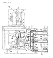
- Fig. 10 is a refrigerant circuit diagram showing a flow of the refrigerant and water during cooling operation in the heat pump according to Embodiment 3.
- Fig. 11 is P-h diagram during heating operation in the heat pump according to Embodiment 3.
- the refrigerant states at points a to g shown in Fig. 11 correspond to the refrigerant states at each position a to g shown in Fig. 10 .
- the following description relates to a case in which all of the indoor units C, D, and E are about to perform a heating operation.
- the four-way switching valve 22 is switched so that refrigerant that has been discharged from the compressor 21 flows into the first branching unit 30.
- the solenoid valve 28a is opened, the solenoid valves 28b, 28c, and 28d are closed, and the solenoid valve 28e is opened, so that the intermediate heat exchanger 40a and the intermediate heat exchanger 40b are serially connected.
- the pipings shown in solid lines are pipings in which refrigerant circulates, and the pipings shown in bold lines are pipings in which water circulates.
- the operation of the compressor 21 is started in the above-described state.
- a low-temperature, low-pressure gas refrigerant is compressed by the compressor 21 and is discharged as a high-temperature, high-pressure gas refrigerant.
- This refrigerant compression process in the compressor is represented by the line between point a and point b in Fig. 11 .
- the high-temperature, high-pressure gas refrigerant that has been discharged from the compressor 21 flows into the intermediate heat exchanger 40a via the four-way switching valve 22 and the second connecting piping 27.
- the refrigerant is cooled while heating the water, and thus becomes a middle-temperature, high-pressure liquid refrigerant.
- the refrigerant change at this time is represented by the slightly inclined straight line that is close to horizontal extending from point b to point c in Fig. 11 .
- the middle-temperature, high-pressure liquid refrigerant that has flowed out of the intermediate heat exchanger 40a passes through the solenoid valve 28e and the first heat exchange unit 51 and then flows into the intermediate heat exchanger 40b (point c ⁇ point d).
- the refrigerant is cooled while heating the water, and becomes a middle-temperature, high-pressure liquid refrigerant.
- the refrigerant change at this time is represented by the slightly inclined straight line that is close to horizontal extending from point d to point e in Fig. 11 .
- the middle-temperature, high-pressure liquid refrigerant that has flowed out of the intermediate heat exchanger 40b passes through the second heat exchange unit 53 (point e ⁇ point f), and then passes through the first flow control device 29b and the third flow control device 33.
- the middle-temperature, high-pressure liquid refrigerant is throttled in the first flow control device 29b and the third flow control device 33 and is expanded and decompressed, and then enters a low-temperature low-pressure two-phase gas-liquid state.
- the refrigerant change at this time is represented by the vertical line extending from point f to point g in Fig. 11 .
- the refrigerant is a single-phase flow in a supercritical state, there are no problems related to refrigerant distribution at the inlet of the intermediate heat exchanger 40b even if the intermediate heat exchangers 40a and 40b are serially connected. Therefore, the flow velocity of the refrigerant flowing through the intermediate heat exchangers 40a and 40b can be increased, and heat exchange can be efficiently carried out.
- the solenoid valves 28a and 28b can be opened, the solenoid valves 28c to 28e can be closed, and the intermediate heat exchangers 40a and 40b can be connected in parallel so that the flow rate is controlled by the first flow control devices 29a and 29b.
- the low-temperature low-pressure two-phase gas-liquid refrigerant that has left the third flow control device 33 flows into the heat source side heat exchanger 23 via the first connecting piping 26 and is heated while cooling the outdoor air, and thus becomes a low-temperature, low-pressure gas refrigerant.
- the refrigerant change in the heat source side heat exchanger 23 is represented by the slightly inclined straight line that is close to horizontal extending from point g to point a in Fig. 11 .
- the low-temperature, low-pressure gas refrigerant that has left the heat source side heat exchanger 23 passes through the four-way switching valve 22 and flows into the compressor 21.
- the low-temperature, low-pressure gas refrigerant that has flowed into the compressor 21 is compressed again in the compressor 21.
- the passages of the indoor heat exchangers 25c, 25d, and 25e can be connected to either of the intermediate heat exchangers.
- the flow switching valves 42c to 42n can be opened/closed so that the passages of the indoor heat exchangers 25c, 25d, and 25e are connected to either of the intermediate heat exchangers.
- the water which has been heated in one of the intermediate heat exchangers 40a and 40b is made to flow into the indoor heat exchangers 25c, 25d, and 25e by the pumps 41 a and 41 b to heat the conditioned space in which the indoor heat exchangers 25c, 25d, and 25e are installed.
- the opening degree of the flow control devices 43c in accordance with each indoor cooling load and the like, the flow rate of water flowing into the indoor heat exchangers 25c, 25d, and 25e can be controlled.
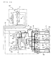
- Fig. 12 is a refrigerant circuit diagram showing a flow of the refrigerant and water during cooling main operation in the heat pump according to Embodiment 3.
- Fig. 13 is P-h diagram during cooling main operation in the heat pump according to Embodiment 3.
- the refrigerant states at points a to h shown in Fig. 13 correspond to the refrigerant states at each position a to h shown in Fig. 12 .
- the following description relates to a case in which the indoor units C and D are cooling and the indoor unit E is heating.
- the four-way switching valve 22 is switched so that refrigerant that has been discharged from the compressor 21 flows into the heat source side heat exchanger 23.
- the solenoid valves 28b and 28c are opened, the solenoid valves 28a and 28d are closed, and the solenoid valve 28e is closed.
- the intermediate heat exchanger 40a produces cold water
- the intermediate heat exchanger 40b produces hot water.
- the heat source side heat exchanger 23 and the intermediate heat exchanger 40b that produces hot water are serially connected as radiators.
- the pipings shown in solid lines are pipings in which refrigerant circulates
- the pipings shown in bold lines are pipings in which water circulates.
- the operation of the compressor 21 is started in the above-described state.
- a low-temperature, low-pressure gas refrigerant is compressed by the compressor 21 and is discharged as a high-temperature, high-pressure gas refrigerant.
- This refrigerant compression process in the compressor is represented by the line between point a and point b in Fig. 13 .
- the high-temperature, high-pressure gas refrigerant that has been discharged from the compressor 21 flows into the heat source side heat exchanger 23 through the four-way switching valve 22.
- the refrigerant that has flowed into the heat source side heat exchanger 23 is cooled while heating the outdoor air, leaving an amount of heat necessary for heating, and is turned into a middle-temperature, high-pressure refrigerant.
- the refrigerant change in the outdoor heat exchanger 23 is represented by the slightly inclined straight line that is close to horizontal extending from point b to point c in Fig. 13 .
- the middle-temperature, high-pressure refrigerant that has flowed out of the heat source side heat exchanger 23 passes through the second connecting piping 27 and the first heat exchange unit 51, and flows into the intermediate heat exchanger 40b that produces hot water.
- the refrigerant undergoes hardly any change at this time, and reaches the state shown by point d in Fig. 13 .
- the middle-temperature, high-pressure refrigerant that has flowed into the intermediate heat exchanger 40b is cooled while heating the hot water in the intermediate heat exchanger 40b, and thus becomes a middle-temperature, high-pressure liquid refrigerant.
- the refrigerant change in the intermediate heat exchanger 40b is represented by the slightly inclined straight line that is close to horizontal extending from point d to point e in Fig. 13 .
- the refrigerant that has flowed out of the intermediate heat exchanger 40b that produces hot water passes through the second heat exchange unit 53 (point e ⁇ point f), and then passes through the first flow control devices 29b and 29a.
- the middle-temperature, high-pressure liquid refrigerant is throttled in the first flow control devices 29b and 29a and is expanded and decompressed, and then enters a low-temperature low-pressure two-phase gas-liquid state.
- the refrigerant change in the first flow control devices 29b and 29a is carried out under a constant enthalpy.
- the refrigerant change at this time is represented by the vertical line extending from point f to point g in Fig. 13 .
- the low-temperature low-pressure two-phase gas-liquid refrigerant that has left the first flow control devices 29a and 29b flows into the intermediate heat exchanger 40a that produces cold water.
- the low-temperature, low-pressure two-phase gas-liquid refrigerant that has flowed into the intermediate heat exchanger 40a that produces cold water is heated while cooling the water to become a low-temperature, low-pressure gas refrigerant.
- the refrigerant change in the intermediate heat exchanger 40a is represented by the slightly inclined straight line that is close to horizontal extending from point g to point h in Fig. 13 .
- the low-temperature, low-pressure gas refrigerant that has left the intermediate heat exchanger 40a flows into the first branching unit 30 (more specifically, the solenoid valve 28c).
- the low-temperature, low-pressure gas refrigerant that has flowed into the first branching unit 30 passes through the first connecting piping 26 and the four-way switching valve 22 to reach point a in Fig. 13 , and then flows into the compressor 21.
- the low-temperature, low-pressure gas refrigerant that has flowed into the compressor 21 is compressed again in the compressor 21.
- the flow switching valves 42c and 42n are opened/closed to form a passage in which the intermediate heat exchanger 40b that produces hot water and the indoor unit E that performs heating are connected, and a passage in which the intermediate heat exchanger 40a that produces cold water and the indoor units C and D that perform cooling are connected.
- the hot water made to flow into the indoor heat exchanger 25e by the pump 41 b heats the conditioned space in which the indoor unit E is installed.
- the opening degree of the flow control device 43c in accordance with the indoor heating load and the like where the indoor unit E is installed, the flow rate of water flowing into the indoor heat exchanger 25e can be controlled.
- the cold water made to flow into the indoor heat exchangers 25c and 25d by the pump 41a cools the conditioned spaces in which the indoor units C and D are installed.
- the opening degree of the flow control devices 43c in accordance with the indoor cooling load and the like where the indoor units C and D are installed, the flow rate of water flowing into the indoor heat exchangers 25c and 25d can be controlled.
- Fig. 14 is a refrigerant circuit diagram showing a flow of the refrigerant and water during heating main operation in the heat pump according to Embodiment 3.
- Fig. 15 is a P-h diagram during heating main operation in the heat pump according to Embodiment 3.
- the refrigerant states at points a to e shown in Fig. 15 correspond to the refrigerant states at each position a to e shown in Fig. 14 .
- the following description relates to a case in which the indoor unit C is cooling and the indoor units D and E are heating.
- the four-way switching valve 22 is switched so that refrigerant that has been discharged from the compressor 21 flows into the first branching unit 30.
- the solenoid valves 28b and 28c are opened, the solenoid valves 28a and 28d are closed, and the solenoid valve 28e is closed.
- the intermediate heat exchanger 40a produces cold water
- the intermediate heat exchanger 40b produces hot water.
- the pipings shown in solid lines are pipings in which refrigerant circulates
- the pipings shown in bold lines are pipings in which water circulates.
- the operation of the compressor 21 is started in the above-described state.
- a low-temperature, low-pressure gas refrigerant is compressed by the compressor 21 and is discharged as a high-temperature, high-pressure gas refrigerant.
- This refrigerant compression process in the compressor is represented by the line between point a and point b in Fig. 15 .
- the high-temperature, high-pressure gas refrigerant that has been discharged from the compressor 21 flows into the intermediate heat exchanger 40b that produces hot water via the four-way switching valve 22 and the second connecting piping 27.
- the high-temperature, high-pressure gas refrigerant that has flowed into the intermediate heat exchanger 40b is cooled while heating the water, and thus becomes a middle-temperature, high-pressure liquid refrigerant.
- the refrigerant change in the intermediate heat exchanger 40b is represented by the slightly inclined straight line that is close to horizontal extending from point b to point c in Fig. 15 .
- the middle-temperature, high-pressure liquid refrigerant that has flowed out of the intermediate heat exchanger 40b passes through the first flow control devices 29b and 29a.
- the middle-temperature, high-pressure liquid refrigerant is throttled in the first flow control devices 29b and 29a and is expanded and decompressed, and then enters a low-temperature low-pressure two-phase gas-liquid state.
- the refrigerant change at this time is represented by the vertical line extending from point c to point d in Fig. 15 .
- the low-temperature low-pressure two-phase gas-liquid refrigerant that has left the first flow control device 29a flows into the intermediate heat exchanger 40a that produces cold water.
- the low-temperature low-pressure two-phase gas-liquid refrigerant that has flowed into the intermediate heat exchanger 40a is heated while cooling the cold water to become a low-temperature, low-pressure two-phase gas-liquid refrigerant.
- the refrigerant change at this time is represented by the slightly inclined straight line that is close to horizontal extending from point d to point e in Fig. 15 .
- the low-temperature low-pressure two-phase gas-liquid refrigerant that has left the intermediate heat exchanger 40a passes through the first connecting piping 26 and flows into the heat source side heat exchanger 23.
- the low-temperature low-pressure two-phase gas-liquid refrigerant that has flowed into the heat source side heat exchanger 23 receives heat from the outdoor air and becomes a low-temperature, low-pressure gas refrigerant.
- the refrigerant change at this time is represented by the slightly inclined straight line that is close to horizontal extending from point e to point a in Fig. 15 .
- the low-temperature, low-pressure gas refrigerant that has left the heat source side heat exchanger 23 passes through the four-way switching valve 22 and flows into the compressor 21.
- the low-temperature, low-pressure gas refrigerant that has flowed into the compressor 21 is compressed again in the compressor 21.
- the flow switching valves 42c and 42n are opened/closed to form a passage in which the intermediate heat exchanger 40b that produces hot water and the indoor units D and E that perform heating are connected, and a passage in which the intermediate heat exchanger 40a that produces cold water and the indoor unit C that performs cooling are connected.
- the hot water that flows into the indoor heat exchangers 25d and 25e by the pump 41 b heats the conditioned spaces in which the indoor units D and E are installed.
- the opening degree of the flow control devices 43c in accordance with the indoor heating load or the like where the indoor units D and E are installed, the flow rate of water flowing into the indoor heat exchangers 25d and 25e can be controlled.
- the cold water made to flow into the indoor heat exchangers 25c and 25d by the pump 41 a cools the conditioned spaces in which the indoor units C and D are installed.
- the opening degree of the flow control device 43c in accordance with the indoor cooling load and the like where the indoor unit C is installed, the flow rate of water flowing into the indoor heat exchanger 25c can be controlled.
- Fig. 16 is a diagram showing a flow of the refrigerant and water when the secondary-side cycle is operated in the heating operation mode of the heat pump according to Embodiment 3.
- Fig. 17 is a P-h diagram when the secondary-side cycle is operated in the heating operation mode of the heat pump according to Embodiment 3.
- the refrigerant states at points a to g shown in Fig. 17 correspond to the refrigerant states at each position a to g shown in Fig. 16 .
- the pipings shown in solid lines are pipings in which refrigerant circulates
- the pipings shown in bold lines are pipings in which water circulates.
- the flow of the primary-side refrigerant and the water shown in Fig. 16 is the same as the flow of the primary-side refrigerant and the water shown in Fig. 10 , except that in Fig. 16 the secondary-side refrigerant also circulates in the secondary-side refrigeration cycle.
- the primary-side refrigerant that has left the intermediate heat exchanger 40a is heated by the secondary-side refrigerant in the first heat exchange unit 51 (point d). Therefore, the temperature of the primary-side refrigerant that flows into the intermediate heat exchanger 40b rises, and the heat exchange performance in the intermediate heat exchanger 40b improves.
- the primary-side refrigerant that has left the intermediate heat exchanger 40b (point e) is cooled by the secondary-side refrigerant in the second heat exchange unit 53 (point f). Therefore, the heating operation can be carried out efficiently.
- Fig. 18 is a diagram showing a flow of the refrigerant and water when the secondary-side cycle is operated in the cooling main operation mode of the heat pump according to Embodiment 3.
- Fig. 19 is a P-h diagram when the secondary-side cycle is operated in the cooling main operation mode of the heat pump according to Embodiment 3.
- the refrigerant states at points a to h shown in Fig. 19 correspond to the refrigerant states at each position a to f shown in Fig. 18 .
- the pipings shown in solid lines are pipings in which refrigerant circulates
- the pipings shown in bold lines are pipings in which water circulates.
- the flow of the primary-side refrigerant and the water shown in Fig. 12 is the same as the flow of the primary-side refrigerant and the water shown in Fig. 18 , except that in Fig. 18 the secondary-side refrigerant also circulates in the secondary-side refrigeration cycle.
- the primary-side refrigerant that has left the intermediate heat exchanger 40a is heated by the secondary-side refrigerant in the first heat exchange unit 51 (point d). Therefore, the temperature of the primary-side refrigerant that flows into the intermediate heat exchanger 40b rises, and the heat exchange performance in the intermediate heat exchanger 40b improves.
- the primary-side refrigerant that has left the intermediate heat exchanger 40b (point e) is cooled by the secondary-side refrigerant in the second heat exchange unit 53 (point f). Therefore, the amount cooled from point e ⁇ point f can be used to heat the hot water, and the cooling main operation can be carried out efficiently.
- Fig. 20 is a refrigerant circuit diagram showing another example of the heat pump according to Embodiment 3.
- a heat pump 105 according to Embodiment 3 differs from the heat pump 104 in that the check valves 35 to 38 are not provided as flow switching valves.
- the direction of refrigerant flowing through the first connecting piping 26 and the direction of refrigerant flowing through the second connecting piping 27 are opposite to those in the heat pump 144.
- the opening and closing of the solenoid valves 28a to 28d are also opposite to those in heat pump 104.
- COP can be greatly improved.
- Fig. 21 is a refrigerant circuit diagram showing a further example of the heat pump according to Embodiment 3.
- a heat pump 106 according to Embodiment 3
- a water piping 44 that connects the water piping downstream of the pump 41 b and the water piping upstream of the intermediate heat exchanger 40a is provided.
- a flow switching valve 44c is provided to the water piping 44.
- a flow switching valve 44b is provided to the water piping downstream of the pump 41 b at a location further downstream than the connection part with the water piping 44.
- a flow switching valve 44a is provided to the water piping upstream of the intermediate heat exchanger 40a at a location further upstream than the connection part with the water piping 44.
- the heat pump 106 is the same as the heat pump 104.
- the intermediate heat exchangers 40a and 40b can be serially connected also in the water-side circuit.
- the intermediate heat exchangers 40a and 40b can be connected in parallel.
- the intermediate heat exchangers 40a and 40b are serially connected, and in the other operation modes, the intermediate heat exchangers 40a and 40b are connected in parallel.
- the intermediate heat exchangers 40a and 40b are serially connected, and thus the flow velocity of the water can be increased and heat exchange can be carried out efficiently.
- COP in this circuit also, in the heating operation mode and the cooling main operation mode, by operating the secondary-side refrigeration cycle as described above, COP can be greatly improved.
- Fig. 22 is a refrigerant circuit diagram showing a further example of the heat pump according to Embodiment 3.
- a heat pump 107 according to Embodiment 3 differs from the heat pump 105 in that a third connecting piping 45 that connects the discharge piping of the compressor 1 with the solenoid valves 28a and 28b is provided so that refrigerant that has been discharged from the compressor 1 flows directly into the intermediate heat exchangers 40a and 40b.
- the second flow control device 32 is provided to the second connecting piping 27, it may be in the heat source unit A or in the relay unit B.
- the intermediate heat exchanger performing heating in the cooling main operation mode and the heat source side heat exchanger 23 were serially connected, and the intermediate heat exchanger performing cooling in the heating main operation mode and the heat source-unit side heat exchanger 23 were serially connected.
- the intermediate heat exchanger performing heating in the cooling main operation mode and the heat source side heat exchanger 23 are connected in parallel, and the intermediate heat exchanger performing cooling in the heating main operation mode and the heat source side heat exchanger 23 are connected in parallel.
- COP in the heating operation mode, by operating the secondary-side refrigeration cycle as described above, COP can be greatly improved.
- the heat pumps 105 to 107 may also be configured as circuits in which the internal heat exchanger 34 and the second bypass piping 39b are not provided.
- the water-side circuit may be configured as a circuit in which the intermediate heat exchangers 40a and 40b are serially connected.
- the four-way switching valve 22 in the heat pumps 104 to 107 is not limited thereto, and the circuit switching function can be alternatively achieved by installing a plurality of opening/closing valves (solenoid valves) or three-way valves.
- heat transport to the indoor units C, D, and E is carried out by water.
- the primary-side refrigerant and secondary-side refrigerant can be prevented from penetrating into the indoors. Hence, a safe heat pump can be obtained.
- the flow control devices When heat transport from the relay unit B to the indoor units C, D, and E is carried out by a refrigerant, the flow control devices are normally installed near the indoor units C, D, and E.
- the flow control devices 43c when heat transport from the relay unit B to the indoor units C, D, and E is carried out by water, it is possible to install the flow control devices 43c in the relay unit B because temperature of water flowing in the water piping is not changed by pressure loss.
- the conditioned space can be air conditioned. Since the flow control devices 43c are separated away from the conditioned space, noise to the conditioned space such as driving of the control valves or flowing noise of the refrigerant when passing through the valves can be reduced.
- control of the flow control devices 43c connected to the indoor heat exchangers 25c, 25d, and 25e can be collectively carried out in the relay unit B.
- Control in the indoor units C, D, and E can be limited to only control of the fan based on information such as the setting status of an indoor unit remote control, thermo off, and whether the heat source unit A is defrosting.
- the pumps 41 a and 41 b used for driving water can be reduced in size, and the power for transporting water can be reduced, thus achieving energy saving.
Landscapes
- Engineering & Computer Science (AREA)
- Physics & Mathematics (AREA)
- Mechanical Engineering (AREA)
- Thermal Sciences (AREA)
- General Engineering & Computer Science (AREA)
- Steam Or Hot-Water Central Heating Systems (AREA)
- Other Air-Conditioning Systems (AREA)
- Compression-Type Refrigeration Machines With Reversible Cycles (AREA)
Applications Claiming Priority (1)
| Application Number | Priority Date | Filing Date | Title |
|---|---|---|---|
| PCT/JP2009/068358 WO2011052031A1 (ja) | 2009-10-27 | 2009-10-27 | ヒートポンプ |
Publications (3)
| Publication Number | Publication Date |
|---|---|
| EP2495510A1 true EP2495510A1 (de) | 2012-09-05 |
| EP2495510A4 EP2495510A4 (de) | 2016-10-12 |
| EP2495510B1 EP2495510B1 (de) | 2017-08-16 |
Family
ID=43921475
Family Applications (1)
| Application Number | Title | Priority Date | Filing Date |
|---|---|---|---|
| EP09850811.2A Active EP2495510B1 (de) | 2009-10-27 | 2009-10-27 | Wärmepumpe |
Country Status (5)
| Country | Link |
|---|---|
| US (1) | US9593872B2 (de) |
| EP (1) | EP2495510B1 (de) |
| JP (1) | JP5496217B2 (de) |
| CN (1) | CN102597658B (de) |
| WO (1) | WO2011052031A1 (de) |
Cited By (4)
| Publication number | Priority date | Publication date | Assignee | Title |
|---|---|---|---|---|
| EP3343131A1 (de) * | 2017-01-03 | 2018-07-04 | Heatcraft Refrigeration Products LLC | System und verfahren zur wiederverwendung von abwärme einer transkritischen kälteanlage |
| EP3351871A1 (de) * | 2017-01-03 | 2018-07-25 | Heatcraft Refrigeration Products LLC | System und verfahren zur wiederverwendung von abwärme einer transkritischen kälteanlage |
| EP3334986A4 (de) * | 2015-12-18 | 2018-12-12 | Samsung Electronics Co., Ltd. | Ausseneinheit für klimaanlage mit wärmeaustauschvorrichtung |
| US10634394B2 (en) | 2015-12-18 | 2020-04-28 | Samsung Electronics Co., Ltd. | Air conditioner outdoor unit including heat exchange apparatus |
Families Citing this family (30)
| Publication number | Priority date | Publication date | Assignee | Title |
|---|---|---|---|---|
| JP5815284B2 (ja) * | 2011-05-20 | 2015-11-17 | 株式会社日本自動車部品総合研究所 | 冷却装置 |
| EP2759787B1 (de) * | 2011-09-13 | 2019-07-24 | Mitsubishi Electric Corporation | Wärmepumpenvorrichtung |
| EP2808625B1 (de) * | 2012-01-24 | 2020-05-20 | Mitsubishi Electric Corporation | Kältelmittelnachfüllverfahren für eine klimaanlage |
| DE102012215971A1 (de) * | 2012-09-10 | 2014-05-28 | Bayerische Motoren Werke Aktiengesellschaft | Verfahren zum thermischen Konditionieren eines Verbrennungsmotors und/oder eines Fahrgastraums eines Fahrzeugs sowie Fahrzeug |
| DE102012222594B4 (de) * | 2012-12-10 | 2018-05-17 | Bayerische Motoren Werke Aktiengesellschaft | Verfahren zum Betreiben eines Kältemittelkreislaufs als Wärmepumpe sowie als Wärmepumpe betreibbarer Kältemittelkreislauf |
| US9995509B2 (en) * | 2013-03-15 | 2018-06-12 | Trane International Inc. | Cascading heat recovery using a cooling unit as a source |
| JPWO2016059837A1 (ja) * | 2014-10-16 | 2017-08-03 | サンデンホールディングス株式会社 | ヒートポンプ式暖房装置 |
| JP6540074B2 (ja) * | 2015-02-17 | 2019-07-10 | 株式会社富士通ゼネラル | 空気調和装置 |
| CN104930578B (zh) * | 2015-05-21 | 2018-05-01 | 广东美的暖通设备有限公司 | 一种带室内机的热泵直热式采暖系统 |
| JP6537986B2 (ja) * | 2016-01-26 | 2019-07-03 | 伸和コントロールズ株式会社 | 温度制御システム |
| CN107024017A (zh) * | 2017-03-23 | 2017-08-08 | 北京国科天创建筑设计院有限责任公司 | 一种高进水温度的复迭式二氧化碳热泵系统 |
| CN107804142B (zh) * | 2017-10-19 | 2023-08-08 | 珠海格力电器股份有限公司 | 一种热泵系统、电动汽车及其热泵控制方法 |
| CN108106036B (zh) * | 2017-12-05 | 2023-10-27 | 广东申菱环境系统股份有限公司 | 一种利用复叠式制冷系统余热的热泵 |
| US10648701B2 (en) * | 2018-02-06 | 2020-05-12 | Thermo Fisher Scientific (Asheville) Llc | Refrigeration systems and methods using water-cooled condenser and additional water cooling |
| KR20190120936A (ko) * | 2018-04-17 | 2019-10-25 | 한온시스템 주식회사 | 차량의 열관리 시스템 |
| IL260159B (en) * | 2018-06-19 | 2022-02-01 | N A M Tech Ltd | A cooling system consisting of multiple cascades |
| US11346570B2 (en) * | 2018-11-29 | 2022-05-31 | Daikin Industries, Ltd. | Refrigerant leakage determination system and refrigeration cycle apparatus |
| CN109579191B (zh) * | 2018-12-25 | 2021-07-13 | 荏原冷热系统(中国)有限公司 | 双压缩机空调系统及其冷剂循环量的控制方法、控制装置 |
| KR102533382B1 (ko) * | 2019-01-09 | 2023-05-19 | 한온시스템 주식회사 | 열관리 시스템 |
| CN111520928B (zh) | 2019-02-02 | 2023-10-24 | 开利公司 | 增强热驱动的喷射器循环 |
| CN111520932B8 (zh) * | 2019-02-02 | 2023-07-04 | 开利公司 | 热回收增强制冷系统 |
| CN110068219A (zh) * | 2019-03-15 | 2019-07-30 | 南京航空航天大学 | 带有储热装置的热泵干燥系统及其工作方法 |
| KR102746984B1 (ko) * | 2019-03-27 | 2024-12-27 | 엘지전자 주식회사 | 공기조화 장치 |
| KR102703178B1 (ko) * | 2019-08-07 | 2024-09-04 | 현대자동차 주식회사 | 차량용 히트펌프 시스템 |
| CN113646599B (zh) * | 2020-03-10 | 2022-06-17 | Ats日本株式会社 | 制冷剂控制系统及冷却系统 |
| JP6978704B2 (ja) * | 2020-03-31 | 2021-12-08 | ダイキン工業株式会社 | 水加熱システム |
| CN111550944B (zh) * | 2020-04-26 | 2024-03-29 | 珠海格力电器股份有限公司 | 一种三次节流增焓双冷凝制冷系统、空调器和控制方法 |
| JP7843854B2 (ja) * | 2022-10-26 | 2026-04-10 | 三菱電機株式会社 | 空気調和装置 |
| US12516855B2 (en) * | 2022-10-27 | 2026-01-06 | Supercritical Storage Company, Inc. | High-temperature, dual rail heat pump cycle for high performance at high-temperature lift and range |
| CN116209215A (zh) * | 2023-01-03 | 2023-06-02 | 联想(北京)有限公司 | 一种散热模组及数据中心 |
Family Cites Families (14)
| Publication number | Priority date | Publication date | Assignee | Title |
|---|---|---|---|---|
| US3852974A (en) * | 1971-12-03 | 1974-12-10 | T Brown | Refrigeration system with subcooler |
| JPH02290475A (ja) * | 1989-04-28 | 1990-11-30 | Nippondenso Co Ltd | ヒートポンプ式冷暖房装置 |
| JP3985394B2 (ja) | 1999-07-30 | 2007-10-03 | 株式会社デンソー | 冷凍サイクル装置 |
| JP4298990B2 (ja) | 2002-04-26 | 2009-07-22 | パナソニック株式会社 | 二酸化炭素を冷媒として用いた冷凍装置 |
| JP4430363B2 (ja) | 2003-09-16 | 2010-03-10 | 東芝キヤリア株式会社 | 複合式空気調和装置 |
| JP4488712B2 (ja) | 2003-10-08 | 2010-06-23 | 三菱電機株式会社 | 空気調和装置 |
| US7526924B2 (en) * | 2003-11-28 | 2009-05-05 | Mitsubishi Denki Kabushiki Kaisha | Refrigerator and air conditioner |
| KR100565257B1 (ko) * | 2004-10-05 | 2006-03-30 | 엘지전자 주식회사 | 압축기를 이용한 이차냉매사이클 및 이를 구비한 공기조화기 |
| JP2007003169A (ja) * | 2005-06-22 | 2007-01-11 | Noriyuki Yamauchi | 二酸化炭素を冷媒に使用する冷凍・給湯・暖房装置およびそれに用いる凝縮システム |
| JP3982545B2 (ja) * | 2005-09-22 | 2007-09-26 | ダイキン工業株式会社 | 空気調和装置 |
| JP2008002759A (ja) | 2006-06-23 | 2008-01-10 | Matsushita Electric Ind Co Ltd | 二元冷凍システムおよび保冷庫 |
| KR100803144B1 (ko) * | 2007-03-28 | 2008-02-14 | 엘지전자 주식회사 | 공기조화기 |
| JP2008267731A (ja) * | 2007-04-23 | 2008-11-06 | Mitsubishi Electric Corp | 空気調和装置 |
| JP2008292122A (ja) * | 2007-05-28 | 2008-12-04 | Kansai Electric Power Co Inc:The | 蓄熱システム及びこれを用いた蓄熱式空気調和装置 |
-
2009
- 2009-10-27 EP EP09850811.2A patent/EP2495510B1/de active Active
- 2009-10-27 US US13/503,483 patent/US9593872B2/en active Active
- 2009-10-27 WO PCT/JP2009/068358 patent/WO2011052031A1/ja not_active Ceased
- 2009-10-27 JP JP2011538132A patent/JP5496217B2/ja active Active
- 2009-10-27 CN CN200980162230.5A patent/CN102597658B/zh active Active
Non-Patent Citations (3)
| Title |
|---|
| No further relevant documents disclosed * |
| None * |
| See also references of WO2011052031A1 * |
Cited By (5)
| Publication number | Priority date | Publication date | Assignee | Title |
|---|---|---|---|---|
| EP3334986A4 (de) * | 2015-12-18 | 2018-12-12 | Samsung Electronics Co., Ltd. | Ausseneinheit für klimaanlage mit wärmeaustauschvorrichtung |
| US10634394B2 (en) | 2015-12-18 | 2020-04-28 | Samsung Electronics Co., Ltd. | Air conditioner outdoor unit including heat exchange apparatus |
| EP3343131A1 (de) * | 2017-01-03 | 2018-07-04 | Heatcraft Refrigeration Products LLC | System und verfahren zur wiederverwendung von abwärme einer transkritischen kälteanlage |
| EP3351871A1 (de) * | 2017-01-03 | 2018-07-25 | Heatcraft Refrigeration Products LLC | System und verfahren zur wiederverwendung von abwärme einer transkritischen kälteanlage |
| US10605494B2 (en) | 2017-01-03 | 2020-03-31 | Heatcraft Refrigeration Product LLC | System and method for reusing waste heat of a transcritical refrigeration system |
Also Published As
| Publication number | Publication date |
|---|---|
| WO2011052031A1 (ja) | 2011-05-05 |
| US20120204596A1 (en) | 2012-08-16 |
| CN102597658B (zh) | 2014-10-22 |
| EP2495510B1 (de) | 2017-08-16 |
| US9593872B2 (en) | 2017-03-14 |
| JPWO2011052031A1 (ja) | 2013-03-14 |
| JP5496217B2 (ja) | 2014-05-21 |
| CN102597658A (zh) | 2012-07-18 |
| EP2495510A4 (de) | 2016-10-12 |
Similar Documents
| Publication | Publication Date | Title |
|---|---|---|
| EP2495510B1 (de) | Wärmepumpe | |
| JP6685409B2 (ja) | 空気調和装置 | |
| CN104011485B (zh) | 空气调节装置 | |
| EP2492614B1 (de) | Klimaanlage | |
| JP5871959B2 (ja) | 空気調和装置 | |
| EP2472200B1 (de) | Klimaanlage | |
| US9310086B2 (en) | Air-conditioning apparatus | |
| JP5774216B2 (ja) | 多室型空気調和装置 | |
| EP2889559A1 (de) | Klimaanlage | |
| KR101706865B1 (ko) | 공기조화기 | |
| US20120297803A1 (en) | Air-conditioning apparatus | |
| EP3109566B1 (de) | Klimaanlagenvorrichtung | |
| EP2896911B1 (de) | Klimaanlagenvorrichtung | |
| EP2584285B1 (de) | Kälte-klimaanlage | |
| WO2013146415A1 (ja) | ヒートポンプ式加熱装置 | |
| EP1607696A2 (de) | Kältemaschine | |
| EP3715735B1 (de) | Klimatisierungsvorrichtung |
Legal Events
| Date | Code | Title | Description |
|---|---|---|---|
| PUAI | Public reference made under article 153(3) epc to a published international application that has entered the european phase |
Free format text: ORIGINAL CODE: 0009012 |
|
| 17P | Request for examination filed |
Effective date: 20120424 |
|
| AK | Designated contracting states |
Kind code of ref document: A1 Designated state(s): AT BE BG CH CY CZ DE DK EE ES FI FR GB GR HR HU IE IS IT LI LT LU LV MC MK MT NL NO PL PT RO SE SI SK SM TR |
|
| DAX | Request for extension of the european patent (deleted) | ||
| RA4 | Supplementary search report drawn up and despatched (corrected) |
Effective date: 20160913 |
|
| RIC1 | Information provided on ipc code assigned before grant |
Ipc: F25B 1/00 20060101AFI20160907BHEP Ipc: F25B 7/00 20060101ALI20160907BHEP Ipc: F25B 6/04 20060101ALI20160907BHEP |
|
| GRAP | Despatch of communication of intention to grant a patent |
Free format text: ORIGINAL CODE: EPIDOSNIGR1 |
|
| INTG | Intention to grant announced |
Effective date: 20170412 |
|
| GRAS | Grant fee paid |
Free format text: ORIGINAL CODE: EPIDOSNIGR3 |
|
| GRAA | (expected) grant |
Free format text: ORIGINAL CODE: 0009210 |
|
| AK | Designated contracting states |
Kind code of ref document: B1 Designated state(s): AT BE BG CH CY CZ DE DK EE ES FI FR GB GR HR HU IE IS IT LI LT LU LV MC MK MT NL NO PL PT RO SE SI SK SM TR |
|
| REG | Reference to a national code |
Ref country code: GB Ref legal event code: FG4D |
|
| REG | Reference to a national code |
Ref country code: CH Ref legal event code: EP |
|
| REG | Reference to a national code |
Ref country code: IE Ref legal event code: FG4D |
|
| REG | Reference to a national code |
Ref country code: AT Ref legal event code: REF Ref document number: 919455 Country of ref document: AT Kind code of ref document: T Effective date: 20170915 |
|
| REG | Reference to a national code |
Ref country code: DE Ref legal event code: R096 Ref document number: 602009047825 Country of ref document: DE |
|
| REG | Reference to a national code |
Ref country code: NL Ref legal event code: MP Effective date: 20170816 |
|
| REG | Reference to a national code |
Ref country code: LT Ref legal event code: MG4D |
|
| REG | Reference to a national code |
Ref country code: AT Ref legal event code: MK05 Ref document number: 919455 Country of ref document: AT Kind code of ref document: T Effective date: 20170816 |
|
| PG25 | Lapsed in a contracting state [announced via postgrant information from national office to epo] |
Ref country code: NL Free format text: LAPSE BECAUSE OF FAILURE TO SUBMIT A TRANSLATION OF THE DESCRIPTION OR TO PAY THE FEE WITHIN THE PRESCRIBED TIME-LIMIT Effective date: 20170816 Ref country code: NO Free format text: LAPSE BECAUSE OF FAILURE TO SUBMIT A TRANSLATION OF THE DESCRIPTION OR TO PAY THE FEE WITHIN THE PRESCRIBED TIME-LIMIT Effective date: 20171116 Ref country code: AT Free format text: LAPSE BECAUSE OF FAILURE TO SUBMIT A TRANSLATION OF THE DESCRIPTION OR TO PAY THE FEE WITHIN THE PRESCRIBED TIME-LIMIT Effective date: 20170816 Ref country code: LT Free format text: LAPSE BECAUSE OF FAILURE TO SUBMIT A TRANSLATION OF THE DESCRIPTION OR TO PAY THE FEE WITHIN THE PRESCRIBED TIME-LIMIT Effective date: 20170816 Ref country code: FI Free format text: LAPSE BECAUSE OF FAILURE TO SUBMIT A TRANSLATION OF THE DESCRIPTION OR TO PAY THE FEE WITHIN THE PRESCRIBED TIME-LIMIT Effective date: 20170816 Ref country code: SE Free format text: LAPSE BECAUSE OF FAILURE TO SUBMIT A TRANSLATION OF THE DESCRIPTION OR TO PAY THE FEE WITHIN THE PRESCRIBED TIME-LIMIT Effective date: 20170816 |
|
| PG25 | Lapsed in a contracting state [announced via postgrant information from national office to epo] |
Ref country code: LV Free format text: LAPSE BECAUSE OF FAILURE TO SUBMIT A TRANSLATION OF THE DESCRIPTION OR TO PAY THE FEE WITHIN THE PRESCRIBED TIME-LIMIT Effective date: 20170816 Ref country code: PL Free format text: LAPSE BECAUSE OF FAILURE TO SUBMIT A TRANSLATION OF THE DESCRIPTION OR TO PAY THE FEE WITHIN THE PRESCRIBED TIME-LIMIT Effective date: 20170816 Ref country code: ES Free format text: LAPSE BECAUSE OF FAILURE TO SUBMIT A TRANSLATION OF THE DESCRIPTION OR TO PAY THE FEE WITHIN THE PRESCRIBED TIME-LIMIT Effective date: 20170816 Ref country code: BG Free format text: LAPSE BECAUSE OF FAILURE TO SUBMIT A TRANSLATION OF THE DESCRIPTION OR TO PAY THE FEE WITHIN THE PRESCRIBED TIME-LIMIT Effective date: 20171116 Ref country code: GR Free format text: LAPSE BECAUSE OF FAILURE TO SUBMIT A TRANSLATION OF THE DESCRIPTION OR TO PAY THE FEE WITHIN THE PRESCRIBED TIME-LIMIT Effective date: 20171117 Ref country code: IS Free format text: LAPSE BECAUSE OF FAILURE TO SUBMIT A TRANSLATION OF THE DESCRIPTION OR TO PAY THE FEE WITHIN THE PRESCRIBED TIME-LIMIT Effective date: 20171216 |
|
| PG25 | Lapsed in a contracting state [announced via postgrant information from national office to epo] |
Ref country code: CZ Free format text: LAPSE BECAUSE OF FAILURE TO SUBMIT A TRANSLATION OF THE DESCRIPTION OR TO PAY THE FEE WITHIN THE PRESCRIBED TIME-LIMIT Effective date: 20170816 Ref country code: DK Free format text: LAPSE BECAUSE OF FAILURE TO SUBMIT A TRANSLATION OF THE DESCRIPTION OR TO PAY THE FEE WITHIN THE PRESCRIBED TIME-LIMIT Effective date: 20170816 Ref country code: RO Free format text: LAPSE BECAUSE OF FAILURE TO SUBMIT A TRANSLATION OF THE DESCRIPTION OR TO PAY THE FEE WITHIN THE PRESCRIBED TIME-LIMIT Effective date: 20170816 |
|
| REG | Reference to a national code |
Ref country code: DE Ref legal event code: R097 Ref document number: 602009047825 Country of ref document: DE |
|
| PG25 | Lapsed in a contracting state [announced via postgrant information from national office to epo] |
Ref country code: SK Free format text: LAPSE BECAUSE OF FAILURE TO SUBMIT A TRANSLATION OF THE DESCRIPTION OR TO PAY THE FEE WITHIN THE PRESCRIBED TIME-LIMIT Effective date: 20170816 Ref country code: MC Free format text: LAPSE BECAUSE OF FAILURE TO SUBMIT A TRANSLATION OF THE DESCRIPTION OR TO PAY THE FEE WITHIN THE PRESCRIBED TIME-LIMIT Effective date: 20170816 Ref country code: IT Free format text: LAPSE BECAUSE OF FAILURE TO SUBMIT A TRANSLATION OF THE DESCRIPTION OR TO PAY THE FEE WITHIN THE PRESCRIBED TIME-LIMIT Effective date: 20170816 Ref country code: EE Free format text: LAPSE BECAUSE OF FAILURE TO SUBMIT A TRANSLATION OF THE DESCRIPTION OR TO PAY THE FEE WITHIN THE PRESCRIBED TIME-LIMIT Effective date: 20170816 Ref country code: SM Free format text: LAPSE BECAUSE OF FAILURE TO SUBMIT A TRANSLATION OF THE DESCRIPTION OR TO PAY THE FEE WITHIN THE PRESCRIBED TIME-LIMIT Effective date: 20170816 |
|
| REG | Reference to a national code |
Ref country code: CH Ref legal event code: PL |
|
| PLBE | No opposition filed within time limit |
Free format text: ORIGINAL CODE: 0009261 |
|
| STAA | Information on the status of an ep patent application or granted ep patent |
Free format text: STATUS: NO OPPOSITION FILED WITHIN TIME LIMIT |
|
| 26N | No opposition filed |
Effective date: 20180517 |
|
| REG | Reference to a national code |
Ref country code: IE Ref legal event code: MM4A |
|
| REG | Reference to a national code |
Ref country code: FR Ref legal event code: ST Effective date: 20180629 |
|
| PG25 | Lapsed in a contracting state [announced via postgrant information from national office to epo] |
Ref country code: CH Free format text: LAPSE BECAUSE OF NON-PAYMENT OF DUE FEES Effective date: 20171031 Ref country code: LU Free format text: LAPSE BECAUSE OF NON-PAYMENT OF DUE FEES Effective date: 20171027 Ref country code: LI Free format text: LAPSE BECAUSE OF NON-PAYMENT OF DUE FEES Effective date: 20171031 |
|
| REG | Reference to a national code |
Ref country code: BE Ref legal event code: MM Effective date: 20171031 |
|
| PG25 | Lapsed in a contracting state [announced via postgrant information from national office to epo] |
Ref country code: SI Free format text: LAPSE BECAUSE OF FAILURE TO SUBMIT A TRANSLATION OF THE DESCRIPTION OR TO PAY THE FEE WITHIN THE PRESCRIBED TIME-LIMIT Effective date: 20170816 Ref country code: FR Free format text: LAPSE BECAUSE OF NON-PAYMENT OF DUE FEES Effective date: 20171031 Ref country code: BE Free format text: LAPSE BECAUSE OF NON-PAYMENT OF DUE FEES Effective date: 20171031 |
|
| PG25 | Lapsed in a contracting state [announced via postgrant information from national office to epo] |
Ref country code: MT Free format text: LAPSE BECAUSE OF NON-PAYMENT OF DUE FEES Effective date: 20171027 |
|
| PG25 | Lapsed in a contracting state [announced via postgrant information from national office to epo] |
Ref country code: IE Free format text: LAPSE BECAUSE OF NON-PAYMENT OF DUE FEES Effective date: 20171027 |
|
| PG25 | Lapsed in a contracting state [announced via postgrant information from national office to epo] |
Ref country code: HU Free format text: LAPSE BECAUSE OF FAILURE TO SUBMIT A TRANSLATION OF THE DESCRIPTION OR TO PAY THE FEE WITHIN THE PRESCRIBED TIME-LIMIT; INVALID AB INITIO Effective date: 20091027 |
|
| PG25 | Lapsed in a contracting state [announced via postgrant information from national office to epo] |
Ref country code: CY Free format text: LAPSE BECAUSE OF NON-PAYMENT OF DUE FEES Effective date: 20170816 |
|
| PG25 | Lapsed in a contracting state [announced via postgrant information from national office to epo] |
Ref country code: MK Free format text: LAPSE BECAUSE OF FAILURE TO SUBMIT A TRANSLATION OF THE DESCRIPTION OR TO PAY THE FEE WITHIN THE PRESCRIBED TIME-LIMIT Effective date: 20170816 |
|
| PG25 | Lapsed in a contracting state [announced via postgrant information from national office to epo] |
Ref country code: TR Free format text: LAPSE BECAUSE OF FAILURE TO SUBMIT A TRANSLATION OF THE DESCRIPTION OR TO PAY THE FEE WITHIN THE PRESCRIBED TIME-LIMIT Effective date: 20170816 |
|
| PG25 | Lapsed in a contracting state [announced via postgrant information from national office to epo] |
Ref country code: PT Free format text: LAPSE BECAUSE OF FAILURE TO SUBMIT A TRANSLATION OF THE DESCRIPTION OR TO PAY THE FEE WITHIN THE PRESCRIBED TIME-LIMIT Effective date: 20170816 |
|
| PG25 | Lapsed in a contracting state [announced via postgrant information from national office to epo] |
Ref country code: HR Free format text: LAPSE BECAUSE OF FAILURE TO SUBMIT A TRANSLATION OF THE DESCRIPTION OR TO PAY THE FEE WITHIN THE PRESCRIBED TIME-LIMIT Effective date: 20170816 |
|
| REG | Reference to a national code |
Ref country code: GB Ref legal event code: 746 Effective date: 20200811 |
|
| REG | Reference to a national code |
Ref country code: DE Ref legal event code: R084 Ref document number: 602009047825 Country of ref document: DE |
|
| P01 | Opt-out of the competence of the unified patent court (upc) registered |
Effective date: 20230512 |
|
| PGFP | Annual fee paid to national office [announced via postgrant information from national office to epo] |
Ref country code: GB Payment date: 20250904 Year of fee payment: 17 |
|
| PGFP | Annual fee paid to national office [announced via postgrant information from national office to epo] |
Ref country code: DE Payment date: 20250902 Year of fee payment: 17 |