EP3343131A1 - System und verfahren zur wiederverwendung von abwärme einer transkritischen kälteanlage - Google Patents
System und verfahren zur wiederverwendung von abwärme einer transkritischen kälteanlage Download PDFInfo
- Publication number
- EP3343131A1 EP3343131A1 EP17209835.2A EP17209835A EP3343131A1 EP 3343131 A1 EP3343131 A1 EP 3343131A1 EP 17209835 A EP17209835 A EP 17209835A EP 3343131 A1 EP3343131 A1 EP 3343131A1
- Authority
- EP
- European Patent Office
- Prior art keywords
- refrigerant
- heat exchanger
- water
- heat
- refrigeration system
- Prior art date
- Legal status (The legal status is an assumption and is not a legal conclusion. Google has not performed a legal analysis and makes no representation as to the accuracy of the status listed.)
- Granted
Links
Images



Classifications
-
- F—MECHANICAL ENGINEERING; LIGHTING; HEATING; WEAPONS; BLASTING
- F25—REFRIGERATION OR COOLING; COMBINED HEATING AND REFRIGERATION SYSTEMS; HEAT PUMP SYSTEMS; MANUFACTURE OR STORAGE OF ICE; LIQUEFACTION SOLIDIFICATION OF GASES
- F25B—REFRIGERATION MACHINES, PLANTS OR SYSTEMS; COMBINED HEATING AND REFRIGERATION SYSTEMS; HEAT PUMP SYSTEMS
- F25B9/00—Compression machines, plants or systems, in which the refrigerant is air or other gas of low boiling point
- F25B9/002—Compression machines, plants or systems, in which the refrigerant is air or other gas of low boiling point characterised by the refrigerant
- F25B9/008—Compression machines, plants or systems, in which the refrigerant is air or other gas of low boiling point characterised by the refrigerant the refrigerant being carbon dioxide
-
- F—MECHANICAL ENGINEERING; LIGHTING; HEATING; WEAPONS; BLASTING
- F24—HEATING; RANGES; VENTILATING
- F24D—DOMESTIC- OR SPACE-HEATING SYSTEMS, e.g. CENTRAL HEATING SYSTEMS; DOMESTIC HOT-WATER SUPPLY SYSTEMS; ELEMENTS OR COMPONENTS THEREFOR
- F24D3/00—Hot-water central heating systems
- F24D3/18—Hot-water central heating systems using heat pumps
-
- F—MECHANICAL ENGINEERING; LIGHTING; HEATING; WEAPONS; BLASTING
- F25—REFRIGERATION OR COOLING; COMBINED HEATING AND REFRIGERATION SYSTEMS; HEAT PUMP SYSTEMS; MANUFACTURE OR STORAGE OF ICE; LIQUEFACTION SOLIDIFICATION OF GASES
- F25B—REFRIGERATION MACHINES, PLANTS OR SYSTEMS; COMBINED HEATING AND REFRIGERATION SYSTEMS; HEAT PUMP SYSTEMS
- F25B29/00—Combined heating and refrigeration systems, e.g. operating alternately or simultaneously
- F25B29/003—Combined heating and refrigeration systems, e.g. operating alternately or simultaneously of the compression type system
-
- F—MECHANICAL ENGINEERING; LIGHTING; HEATING; WEAPONS; BLASTING
- F25—REFRIGERATION OR COOLING; COMBINED HEATING AND REFRIGERATION SYSTEMS; HEAT PUMP SYSTEMS; MANUFACTURE OR STORAGE OF ICE; LIQUEFACTION SOLIDIFICATION OF GASES
- F25B—REFRIGERATION MACHINES, PLANTS OR SYSTEMS; COMBINED HEATING AND REFRIGERATION SYSTEMS; HEAT PUMP SYSTEMS
- F25B30/00—Heat pumps
- F25B30/02—Heat pumps of the compression type
-
- F—MECHANICAL ENGINEERING; LIGHTING; HEATING; WEAPONS; BLASTING
- F25—REFRIGERATION OR COOLING; COMBINED HEATING AND REFRIGERATION SYSTEMS; HEAT PUMP SYSTEMS; MANUFACTURE OR STORAGE OF ICE; LIQUEFACTION SOLIDIFICATION OF GASES
- F25B—REFRIGERATION MACHINES, PLANTS OR SYSTEMS; COMBINED HEATING AND REFRIGERATION SYSTEMS; HEAT PUMP SYSTEMS
- F25B5/00—Compression machines, plants or systems, with several evaporator circuits, e.g. for varying refrigerating capacity
- F25B5/02—Compression machines, plants or systems, with several evaporator circuits, e.g. for varying refrigerating capacity arranged in parallel
-
- F—MECHANICAL ENGINEERING; LIGHTING; HEATING; WEAPONS; BLASTING
- F25—REFRIGERATION OR COOLING; COMBINED HEATING AND REFRIGERATION SYSTEMS; HEAT PUMP SYSTEMS; MANUFACTURE OR STORAGE OF ICE; LIQUEFACTION SOLIDIFICATION OF GASES
- F25B—REFRIGERATION MACHINES, PLANTS OR SYSTEMS; COMBINED HEATING AND REFRIGERATION SYSTEMS; HEAT PUMP SYSTEMS
- F25B6/00—Compression machines, plants or systems, with several condenser circuits
- F25B6/04—Compression machines, plants or systems, with several condenser circuits arranged in series
-
- F—MECHANICAL ENGINEERING; LIGHTING; HEATING; WEAPONS; BLASTING
- F25—REFRIGERATION OR COOLING; COMBINED HEATING AND REFRIGERATION SYSTEMS; HEAT PUMP SYSTEMS; MANUFACTURE OR STORAGE OF ICE; LIQUEFACTION SOLIDIFICATION OF GASES
- F25B—REFRIGERATION MACHINES, PLANTS OR SYSTEMS; COMBINED HEATING AND REFRIGERATION SYSTEMS; HEAT PUMP SYSTEMS
- F25B9/00—Compression machines, plants or systems, in which the refrigerant is air or other gas of low boiling point
- F25B9/10—Compression machines, plants or systems, in which the refrigerant is air or other gas of low boiling point with several cooling stages
-
- F—MECHANICAL ENGINEERING; LIGHTING; HEATING; WEAPONS; BLASTING
- F24—HEATING; RANGES; VENTILATING
- F24D—DOMESTIC- OR SPACE-HEATING SYSTEMS, e.g. CENTRAL HEATING SYSTEMS; DOMESTIC HOT-WATER SUPPLY SYSTEMS; ELEMENTS OR COMPONENTS THEREFOR
- F24D17/00—Domestic hot-water supply systems
- F24D17/0005—Domestic hot-water supply systems using recuperation of waste heat
- F24D17/001—Domestic hot-water supply systems using recuperation of waste heat with accumulation of heated water
-
- F—MECHANICAL ENGINEERING; LIGHTING; HEATING; WEAPONS; BLASTING
- F24—HEATING; RANGES; VENTILATING
- F24D—DOMESTIC- OR SPACE-HEATING SYSTEMS, e.g. CENTRAL HEATING SYSTEMS; DOMESTIC HOT-WATER SUPPLY SYSTEMS; ELEMENTS OR COMPONENTS THEREFOR
- F24D17/00—Domestic hot-water supply systems
- F24D17/02—Domestic hot-water supply systems using heat pumps
-
- F—MECHANICAL ENGINEERING; LIGHTING; HEATING; WEAPONS; BLASTING
- F24—HEATING; RANGES; VENTILATING
- F24D—DOMESTIC- OR SPACE-HEATING SYSTEMS, e.g. CENTRAL HEATING SYSTEMS; DOMESTIC HOT-WATER SUPPLY SYSTEMS; ELEMENTS OR COMPONENTS THEREFOR
- F24D2200/00—Heat sources or energy sources
- F24D2200/16—Waste heat
- F24D2200/24—Refrigeration
-
- F—MECHANICAL ENGINEERING; LIGHTING; HEATING; WEAPONS; BLASTING
- F24—HEATING; RANGES; VENTILATING
- F24D—DOMESTIC- OR SPACE-HEATING SYSTEMS, e.g. CENTRAL HEATING SYSTEMS; DOMESTIC HOT-WATER SUPPLY SYSTEMS; ELEMENTS OR COMPONENTS THEREFOR
- F24D2220/00—Components of central heating installations excluding heat sources
- F24D2220/20—Heat consumers
- F24D2220/2081—Floor or wall heating panels
-
- F—MECHANICAL ENGINEERING; LIGHTING; HEATING; WEAPONS; BLASTING
- F24—HEATING; RANGES; VENTILATING
- F24D—DOMESTIC- OR SPACE-HEATING SYSTEMS, e.g. CENTRAL HEATING SYSTEMS; DOMESTIC HOT-WATER SUPPLY SYSTEMS; ELEMENTS OR COMPONENTS THEREFOR
- F24D3/00—Hot-water central heating systems
- F24D3/12—Tube and panel arrangements for ceiling, wall, or underfloor heating
- F24D3/14—Tube and panel arrangements for ceiling, wall, or underfloor heating incorporated in a ceiling, wall or floor
-
- F—MECHANICAL ENGINEERING; LIGHTING; HEATING; WEAPONS; BLASTING
- F25—REFRIGERATION OR COOLING; COMBINED HEATING AND REFRIGERATION SYSTEMS; HEAT PUMP SYSTEMS; MANUFACTURE OR STORAGE OF ICE; LIQUEFACTION SOLIDIFICATION OF GASES
- F25B—REFRIGERATION MACHINES, PLANTS OR SYSTEMS; COMBINED HEATING AND REFRIGERATION SYSTEMS; HEAT PUMP SYSTEMS
- F25B2309/00—Gas cycle refrigeration machines
- F25B2309/06—Compression machines, plants or systems characterised by the refrigerant being carbon dioxide
-
- F—MECHANICAL ENGINEERING; LIGHTING; HEATING; WEAPONS; BLASTING
- F25—REFRIGERATION OR COOLING; COMBINED HEATING AND REFRIGERATION SYSTEMS; HEAT PUMP SYSTEMS; MANUFACTURE OR STORAGE OF ICE; LIQUEFACTION SOLIDIFICATION OF GASES
- F25B—REFRIGERATION MACHINES, PLANTS OR SYSTEMS; COMBINED HEATING AND REFRIGERATION SYSTEMS; HEAT PUMP SYSTEMS
- F25B2309/00—Gas cycle refrigeration machines
- F25B2309/06—Compression machines, plants or systems characterised by the refrigerant being carbon dioxide
- F25B2309/061—Compression machines, plants or systems characterised by the refrigerant being carbon dioxide with cycle highest pressure above the supercritical pressure
-
- F—MECHANICAL ENGINEERING; LIGHTING; HEATING; WEAPONS; BLASTING
- F25—REFRIGERATION OR COOLING; COMBINED HEATING AND REFRIGERATION SYSTEMS; HEAT PUMP SYSTEMS; MANUFACTURE OR STORAGE OF ICE; LIQUEFACTION SOLIDIFICATION OF GASES
- F25B—REFRIGERATION MACHINES, PLANTS OR SYSTEMS; COMBINED HEATING AND REFRIGERATION SYSTEMS; HEAT PUMP SYSTEMS
- F25B2339/00—Details of evaporators; Details of condensers
- F25B2339/04—Details of condensers
- F25B2339/047—Water-cooled condensers
-
- F—MECHANICAL ENGINEERING; LIGHTING; HEATING; WEAPONS; BLASTING
- F25—REFRIGERATION OR COOLING; COMBINED HEATING AND REFRIGERATION SYSTEMS; HEAT PUMP SYSTEMS; MANUFACTURE OR STORAGE OF ICE; LIQUEFACTION SOLIDIFICATION OF GASES
- F25B—REFRIGERATION MACHINES, PLANTS OR SYSTEMS; COMBINED HEATING AND REFRIGERATION SYSTEMS; HEAT PUMP SYSTEMS
- F25B2400/00—Component parts or details not otherwise provided for in this subclass
- F25B2400/13—Economisers
-
- F—MECHANICAL ENGINEERING; LIGHTING; HEATING; WEAPONS; BLASTING
- F25—REFRIGERATION OR COOLING; COMBINED HEATING AND REFRIGERATION SYSTEMS; HEAT PUMP SYSTEMS; MANUFACTURE OR STORAGE OF ICE; LIQUEFACTION SOLIDIFICATION OF GASES
- F25B—REFRIGERATION MACHINES, PLANTS OR SYSTEMS; COMBINED HEATING AND REFRIGERATION SYSTEMS; HEAT PUMP SYSTEMS
- F25B2400/00—Component parts or details not otherwise provided for in this subclass
- F25B2400/22—Refrigeration systems for supermarkets
-
- F—MECHANICAL ENGINEERING; LIGHTING; HEATING; WEAPONS; BLASTING
- F25—REFRIGERATION OR COOLING; COMBINED HEATING AND REFRIGERATION SYSTEMS; HEAT PUMP SYSTEMS; MANUFACTURE OR STORAGE OF ICE; LIQUEFACTION SOLIDIFICATION OF GASES
- F25B—REFRIGERATION MACHINES, PLANTS OR SYSTEMS; COMBINED HEATING AND REFRIGERATION SYSTEMS; HEAT PUMP SYSTEMS
- F25B41/00—Fluid-circulation arrangements
- F25B41/30—Expansion means; Dispositions thereof
- F25B41/39—Dispositions with two or more expansion means arranged in series, i.e. multi-stage expansion, on a refrigerant line leading to the same evaporator
-
- Y—GENERAL TAGGING OF NEW TECHNOLOGICAL DEVELOPMENTS; GENERAL TAGGING OF CROSS-SECTIONAL TECHNOLOGIES SPANNING OVER SEVERAL SECTIONS OF THE IPC; TECHNICAL SUBJECTS COVERED BY FORMER USPC CROSS-REFERENCE ART COLLECTIONS [XRACs] AND DIGESTS
- Y02—TECHNOLOGIES OR APPLICATIONS FOR MITIGATION OR ADAPTATION AGAINST CLIMATE CHANGE
- Y02B—CLIMATE CHANGE MITIGATION TECHNOLOGIES RELATED TO BUILDINGS, e.g. HOUSING, HOUSE APPLIANCES OR RELATED END-USER APPLICATIONS
- Y02B30/00—Energy efficient heating, ventilation or air conditioning [HVAC]
-
- Y—GENERAL TAGGING OF NEW TECHNOLOGICAL DEVELOPMENTS; GENERAL TAGGING OF CROSS-SECTIONAL TECHNOLOGIES SPANNING OVER SEVERAL SECTIONS OF THE IPC; TECHNICAL SUBJECTS COVERED BY FORMER USPC CROSS-REFERENCE ART COLLECTIONS [XRACs] AND DIGESTS
- Y02—TECHNOLOGIES OR APPLICATIONS FOR MITIGATION OR ADAPTATION AGAINST CLIMATE CHANGE
- Y02B—CLIMATE CHANGE MITIGATION TECHNOLOGIES RELATED TO BUILDINGS, e.g. HOUSING, HOUSE APPLIANCES OR RELATED END-USER APPLICATIONS
- Y02B30/00—Energy efficient heating, ventilation or air conditioning [HVAC]
- Y02B30/12—Hot water central heating systems using heat pumps
-
- Y—GENERAL TAGGING OF NEW TECHNOLOGICAL DEVELOPMENTS; GENERAL TAGGING OF CROSS-SECTIONAL TECHNOLOGIES SPANNING OVER SEVERAL SECTIONS OF THE IPC; TECHNICAL SUBJECTS COVERED BY FORMER USPC CROSS-REFERENCE ART COLLECTIONS [XRACs] AND DIGESTS
- Y02—TECHNOLOGIES OR APPLICATIONS FOR MITIGATION OR ADAPTATION AGAINST CLIMATE CHANGE
- Y02B—CLIMATE CHANGE MITIGATION TECHNOLOGIES RELATED TO BUILDINGS, e.g. HOUSING, HOUSE APPLIANCES OR RELATED END-USER APPLICATIONS
- Y02B30/00—Energy efficient heating, ventilation or air conditioning [HVAC]
- Y02B30/18—Domestic hot-water supply systems using recuperated or waste heat
Definitions
- This disclosure relates generally to waste heat of a transcritical refrigeration system. More specifically, this disclosure relates to a system and method of reusing waste heat of a transcritical refrigeration system.
- components of a transcritical refrigeration system may discharge heat.
- the heat produced by the components is also referred to as "waste heat.”
- this waste heat is released into the environment because it is too hot to be reused.
- a refrigeration system is operable to circulate refrigerant through the refrigeration system in order to cool a refrigeration load and comprises a gas cooler and a heat exchanger located downstream the gas cooler.
- the gas cooler is operable to receive the refrigerant and apply a first cooling stage to the refrigerant.
- the heat exchanger is operable to receive the refrigerant cooled by the gas cooler, and apply a second cooling stage to the refrigerant, wherein the second cooling stage removing heat from the refrigerant.
- the heat exchanger is further operable to apply the heat removed during the second cooling stage to a water heating system operable to heat water and discharge the refrigerant to an expansion valve operable to supply the refrigerant to the refrigeration load.
- a method for a refrigeration system includes applying, by a gas cooler of the refrigeration system, a first cooling stage to refrigerant circulating through the refrigeration system load. The method further comprises applying, by a heat exchanger located downstream from the gas cooler, a second cooling stage to the refrigerant, wherein the second cooling stage removes heat from the refrigerant, and applying, by the heat exchanger located downstream from the gas cooler, the heat removed during the second cooling stage to a water heating system operable to heat water.
- a heat exchanger is operable to receive refrigerant cooled by a gas cooler of a refrigeration system and apply a cooling stage to the received refrigerant, wherein the cooling stage removes heat from the refrigerant.
- the heat exchanger is further operable to apply the heat removed during the cooling stage to a water heating system operable to heat water and discharge the cooled refrigerant to an expansion valve operable to supply the refrigerant to a refrigeration load of the refrigeration system.
- Certain embodiments may provide one or more technical advantages. For example, an embodiment of the present disclosure may result in more efficient operation of refrigeration system. As another example, an embodiment of the present disclosure may provide supplemental cooling to refrigerant circulating through the refrigeration system. As yet another example, an embodiment of the present invention may provide heating to one or more additional facility systems such as a floor heating system and/or a water heating system. Certain embodiments may include none, some, or all of the above technical advantages. One or more other technical advantages may be readily apparent to one skilled in the art from the figures, descriptions, and claims included herein.
- FIGURES 1 through 5 of the drawings like numerals being used for like and corresponding parts of the various drawings.
- Transcritical refrigeration systems differ from conventional refrigeration systems in that transcritical systems circulate refrigerant that becomes a supercritical fluid above the critical point.
- the critical point for carbon dioxide (CO 2 ) is 31°C and 73.8 MPa, and above this point, CO 2 becomes a homogenous mixture of vapor and liquid that is called a supercritical fluid.
- This unique characteristic of transcritical refrigerants is associated with certain operational differences between transcritical and conventional refrigeration systems.
- transcritical refrigerants are typically associated with discharge temperatures that are higher than their critical temperatures and discharge pressures that are higher than their critical pressures. When a transcritical refrigerant is at or above its critical temperature and/or pressure, the refrigerant may become a "supercritical fluid" - a homogenous mixture of gas and liquid.
- Supercritical fluid does not undergo two phase changes in a gas cooler as occurs in a condenser of a conventional refrigeration system circulating traditional refrigerant. Rather, supercritical fluid undergoes a single phase change in the gas cooler. Stated differently, the gas cooler in a transcritical refrigeration system receives and cools supercritical fluid and the transcritical refrigerant undergoes a partial state change from a liquid to a gas as it is discharged from an expansion valve.
- typical transcritical systems may include a heat exchanger located upstream of the gas cooler.
- Such heat exchanger may be configured to receive compressed refrigerant from one or more compressors and perform a cooling stage to the refrigerant before discharging the cooled refrigerant to the gas cooler.
- one or more components e.g., gas cooler, heat exchangers
- the waste heat in typical transcritical systems is generally too hot to be reused by another system.
- waste heat from a heat exchanger upstream of a gas cooler may be 110°C.
- the present disclosure contemplates a configuration of a refrigeration system that is operable to provide waste heat to other systems via a heat exchanger located downstream from the gas cooler.
- the present disclosure recognizes utilizing waste heat of a transcritical refrigeration system to heat the floor in a cold room (e.g., freezer).
- the present disclosure recognizes utilizing waste heat of a transcritical refrigeration system to pre-heat tap water. Utilizing waste heat in these and other manners may provide various efficiency benefits for the transcritical refrigeration system and the other systems that the heat is provided to.
- FIGURES 1 and 3 illustrate examples of refrigeration systems 100 operable to apply waste heat to other systems within a facility.
- FIGURE 1 illustrates an example of refrigeration system 100 operable to apply waste heat to a floor heating system 190
- FIGURE 3 illustrates an example of a refrigeration system 100 operable to apply waste heat to a water heating system 300.
- refrigeration system 100 is a transcritical refrigeration system that circulates a transcritical refrigerant such as CO 2.
- Refrigeration system 100 may include one or more compressors 110, one or more heat exchangers 120-140, an expansion valve 150, a flash tank 160, one or more valves 165 corresponding to one or more evaporators 170, and a flash tank valve 180.
- refrigeration system 100 is operable to provide cold liquid refrigerant to evaporators 170.
- the evaporators 170 discharge warm refrigerant vapor to compressors 110 which is then cooled by one or more heat exchangers 120-140 and discharged to expansion valve 150 prior to returning to evaporators 170.
- heat exchanger 140 located downstream from gas cooler 130, may provide heating to other systems in addition to providing supplemental cooling to refrigerant circulating through refrigeration system 100.
- heat exchanger 140 is configured to provide heating to floor heating system 190.
- heat exchanger 140 is configured to provide heating to water heating system 300.
- refrigeration system 100 includes one or more compressors 110.
- Refrigeration system 100 may include any suitable number of compressors 110.
- Compressors 110 may vary by design and/or by capacity.
- some compressor designs may be more energy efficient than other compressor designs and some compressors 110 may have modular capacity ( i.e., capability to vary capacity).
- compressor 110a may be a low-temperature (“LT”) compressor that is configured to compress refrigerant discharged from a LT evaporator (e.g., evaporator 170a) and compressor 110b may be a medium-temperature (“MT”) compressor that is configured to compress refrigerant discharged from a MT evaporator (e.g., MT evaporator 170b) and provide supplemental compression to refrigerant discharged from compressor 110a.
- compressors 110 may be operable to receive refrigerant discharged from evaporators 170 and compress the received refrigerant.
- compressors 110 discharge compressed refrigerant directly to gas cooler 130.
- refrigerant discharged from compressors 110 is directed to another component of refrigeration system 100.
- compressor 110b discharges compressed refrigerant to a first heat exchanger 120, which in turn discharges refrigerant to gas cooler 130.
- Refrigeration system 100 may comprise a heat exchanger located upstream from gas cooler 130 in some embodiments.
- refrigeration system 100 includes first heat exchanger 120 that is upstream of gas cooler 130.
- first heat exchanger 120 receives compressed refrigerant discharged from compressors 110 and provides a first cooling stage to the received refrigerant.
- first heat exchanger 120 may receive refrigerant having a temperature of 107°C from compressors 110 and cool the refrigerant to a temperature of 95°C before discharging the refrigerant to gas cooler 130.
- operation of first heat exchanger 120 results in waste heat.
- waste heat from first heat exchanger 120 may be too hot to be used by other systems.
- waste heat from first heat exchanger 120 may be 90°C and therefore may be referred to as "high-grade heat.”
- first heat exchanger 120 discharges the cooled refrigerant to gas cooler 130 for additional cooling.
- refrigeration system 100 may include a gas cooler 130 in some embodiments.
- Gas cooler 130 may be operable to receive refrigerant (e.g., from heat exchanger 120 and/or compressors 110) and apply a cooling stage to the received refrigerant.
- gas cooler 130 may cool refrigerant between 50 - 80°C.
- gas cooler 130 is a heat exchanger comprising cooler tubes configured to circulate the received refrigerant and coils through which ambient air is forced. Inside gas cooler 130, the coils may absorb heat from the refrigerant, thereby providing cooling to the refrigerant.
- gas cooler receives refrigerant having a temperature of 90°C from first heat exchanger 120 and discharges the refrigerant at a temperature of 38°C to second heat exchanger 140.
- Refrigeration system 100 also includes a second heat exchanger 140 in some embodiments.
- second heat exchanger 140 may be configured to receive cooled refrigerant from gas cooler 130 and apply a cooling stage to the refrigerant.
- second heat exchanger 140 may cool the refrigerant between 3 - 7°C.
- operation of second heat exchanger 140 results in waste heat.
- Waste heat from second heat exchanger 140 may have a temperature that is just above the ambient temperature (e.g., 5°R/2°K above the outdoor air temperature), and therefore may be referred to herein as "low-grade heat." This low-grade heat from second heat exchanger 140 may be reclaimed and used to heat one or more other systems.
- waste heat of second heat exchanger 140 may be reclaimed and provided to ground heating system 190 of FIGURE 1 and/or water heating system 300 of FIGURE 3 .
- second heat exchanger 140 may provide supplemental cooling to refrigerant circulating through refrigeration system and provide heating to systems capable of utilizing low-grade heat. Operation of the cooperating systems will be described in more detail below.
- second heat exchanger 140 discharges the refrigerant to expansion valve 150 after applying a cooling stage.
- refrigeration system 100 includes an expansion valve 150.
- Expansion valve 150 may be configured to receive liquid refrigerant from second heat exchanger 140 and to reduce the pressure of received refrigerant.
- second heat exchanger 140 may discharge liquid refrigerant having a pressure of 100 bar to expansion valve 150, and the refrigerant may be discharged from expansion valve 150 having a pressure of 38 bar.
- this reduction in pressure causes some of the refrigerant to vaporize.
- mixed-state refrigerant e.g., refrigerant vapor and liquid refrigerant
- this mixed-state refrigerant is discharged from expansion valve 150.
- this mixed-state refrigerant is discharged to flash tank 160.
- Refrigeration system 100 may include a flash tank 150 in some embodiments.
- Flash tank 150 may be configured to receive mixed-state refrigerant and separate the received refrigerant into flash gas and liquid refrigerant.
- the flash gas collects near the top of flash tank 160 and the liquid refrigerant is collected in the bottom of flash tank 160.
- the liquid refrigerant flows from flash tank 160 and provides cooling to one or more evaporators (cases) 170 and the flash gas flows to one or more compressors (e.g., compressor 110b) for compression before being discharged to gas cooler 130 for cooling.
- compressors e.g., compressor 110b
- Refrigeration system 100 may include one or more evaporators 170 in some embodiments. As depicted in FIGURES 1 and 3 , refrigeration system 100 includes two evaporators 170. In some embodiments, evaporators 170 are refrigerated cases and/or coolers for storing food and/or beverages that must be kept at particular temperatures. As depicted in FIGURES 1 and 3 , first evaporator 170a is a low-temperature case ("LT" case 170a) and second evaporator 170b is a medium-temperature case (“MT case" 170b).
- LT low-temperature case 170a
- MT case medium-temperature case
- LT case 170a may be configured to receive liquid refrigerant of a first temperature and MT case 160b may be configured to receive liquid refrigerant of a second temperature, wherein the first temperature (e.g., -30°C) is lower in temperature than the second temperature (e.g., -6°C).
- first temperature e.g., -30°C
- second temperature e.g., -6°C
- LT case 170a may be a display case in a grocery store
- MT case 170b may be a cooler in a grocery store.
- the liquid refrigerant leaving flash tank 160 is the same temperature and pressure (e.g., 4°C and 38 bar).
- each valve 165 may be controlled (e.g., by controller 500 of FIGURE 5 ) to adjust the temperature and pressure of the liquid refrigerant.
- valve 165a may be configured to discharge the liquid refrigerant at -30°C and 14 bar to LT case 170a and valve 165b may be configured to discharge the liquid refrigerant at -6°C and 30 bar to MT case 170b.
- each evaporator 170 is associated with a particular valve 165 and the valve 165 controls the temperature and pressure of the liquid refrigerant that reaches the evaporator 170.
- System 100 may also include a flash gas valve 180 in some embodiments.
- Flash gas valve 180 may be configured to open and close to permit or restrict the flow through of flash gas discharged from flash tank 160.
- controller 500 of FIGURE 5 controls the opening and closing of flash gas valve 180. As depicted in FIGURES 1 and 2 , closing flash gas valve 180 may restrict flash gas from flowing to second compressor 110b and opening flash gas valve 180 may permit flow of flash gas to second compressor 110b.
- refrigeration system 100 may include any suitable components.
- refrigeration system 100 may include one or more sensors configured to detect temperature and/or pressure information.
- each of compressors 110, heat exchangers 120, 140, gas cooler 130, flash tank 160, and evaporators 170 include one or more sensors.
- refrigeration system 100 may include a controller operable to communicate with one or more components of refrigeration system 100. An example of a controller of refrigeration system 100 will be explained in further detail below in reference to FIGURE 5 .
- refrigeration system 100 may include an oil separator operable to separate compressor oil from the refrigerant.
- refrigeration system 100 may include other components not mentioned herein.
- FIGURE 1 illustrates refrigeration system 100 operating in cooperation with floor heating system 190.
- Floor heating system 190 may be operable to circulate a second refrigerant and may comprise a pump 192 and one or more coils 195.
- floor heating system, 190 comprises three coils 195a-c.
- Coils 195 may be under-ground floor coils operable to heat the floor of an enclosed space.
- coils 195 may heat the floor of a cold room (e.g., walk-in freezer). Heating the floor of a cold room may be desirable for one or more reasons. For example, it may be desirable to heat the floor of a cold room to protect the floor from freezing.
- pump 192 causes the second refrigerant to circulate throughout coils 195 and through second heat exchanger 140 thereafter.
- the second refrigerant is a substance that can absorb heat as it passes through second heat exchanger 140.
- the second refrigerant may be a glycol solution (e.g., 30% glycol, 70% water).
- Heat exchanger 140 may heat the second refrigerant with low-grade waste heat as the second refrigerant passes through heat exchanger 140.
- the second refrigerant is heated between 1 - 3°C by absorbing low-grade waste heat.
- pump 120 may receive second refrigerant at a temperature of 13°C and force the second refrigerant through coils 195.
- the warmed refrigerant provides heating to coils 195 which is transferred to the cold room floor.
- the second refrigerant cools down as the cold room floor heats up.
- second refrigerant exits coils 195 at a decreased temperature (e.g., 10°C) and is directed to second heat exchanger 140 for a warming stage.
- floor heating system 190 may reclaim low-grade waste heat of second heat exchanger 140 and reduce and/or remove operation of any heating element that would otherwise heat the cold room floor.
- second heat exchanger 140 supplements cooling of the refrigerant circulating through refrigeration system 100 thereby reducing the power otherwise consumed by gas cooler 130.
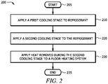
- FIGURE 2 illustrates a method of operation for the refrigeration system configuration of FIGURE 1 .
- the method 200 may be implemented by a controller of refrigeration system 100 (e.g., controller 500 of FIGURE 5 ).
- Method 200 may be stored on a computer readable medium, such as a memory of controller 500 (e.g., memory 520 of FIGURE 5 ), as a series of operating instructions that direct the operation of a processor (e.g., processor 530 of FIGURE 5 ).
- Method 200 may be associated with efficiency benefits such as reduced power consumption relative to refrigeration systems that do not operate heat exchanger downstream from the gas cooler.
- the method 200 begins in step 205 and continues to step 210.
- the refrigeration system applies a first cooling stage to refrigerant circulating through the refrigeration system.
- the component that applies the first cooling stage is a gas cooler (e.g., gas cooler 130 of FIGURE 1 ) of the refrigeration system.
- the refrigerant may be cooled between 10 - 30°K during the first cooling stage.
- gas cooler 130 may receive refrigerant having a temperature of 95°C, apply the first cooling stage to the received refrigerant, and discharge the refrigerant at a temperature of 40°C.
- gas cooler 130 receives the refrigerant from first heat exchanger 120.
- gas cooler 130 discharges the refrigerant to second heat exchanger 140.
- the method 200 may continue to a step 220.
- the refrigeration system applies a second cooling stage to refrigerant circulating through the refrigeration system.
- the component that applies the second cooling stage is a heat exchanger (e.g., second heat exchanger 140 of FIGURE 1 ) of the refrigeration system.
- the heat exchanger that applies the second cooling stage is located downstream from the gas cooler (e.g., gas cooler 130) of the refrigeration system.
- applying the second cooling stage comprises removing heat from the refrigerant. Stated differently, the second cooling stage may cause a reduction in the temperature of the refrigerant.
- the refrigerant may be cooled between 2 - 5°C during the second cooling stage.
- second heat exchanger 140 may receive refrigerant having a temperature of 38°C, apply the second cooling stage to the received refrigerant, and discharge the refrigerant at a temperature of 35°C.
- second heat exchanger 140 receives the refrigerant from gas cooler 130.
- second heat exchanger 140 discharges the refrigerant to expansion valve 150 to supply the refrigerant to a refrigeration load. After applying the second cooling stage to the refrigerant, the method 200 may continue to a step 230.
- the refrigeration system applies the heat removed during step 220 to a floor heating system (e.g., floor heating system 190 of FIGURE 1 ).
- a floor heating system e.g., floor heating system 190 of FIGURE 1
- the component of refrigeration system that applies the heat to the floor heating system is a heat exchanger (e.g., second heat exchanger 140 of FIGURE 1 ).
- the heat exchanger that applies the heat removed during step 220 is located downstream from a gas cooler (e.g., gas cooler 130) of the refrigeration system.
- the refrigeration system applies the heat to a second refrigerant circulating through the floor heating system which is operable to heat the floor of an enclosed space.
- second heat exchanger 140 applies the heat removed from the refrigerant during step 220 to a second refrigerant which in turn heats the floor of an enclosed space (e.g., the floor of a cold room).
- the second refrigerant is heated at least 2°C during step 230.
- the method 200 continues to an end step 235.
- the method 200 may include one or more additional steps in some embodiments.
- the refrigeration system may include another heat exchanger (e.g., first heat exchanger 120) which is also configured to apply a cooling stage to the refrigerant circulating through the refrigeration system.
- method 200 may include a step wherein a third cooling stage is applied by an additional heat exchanger, wherein the additional heat exchanger is located upstream from the gas cooler 130.
- waste heat of a transcritical refrigeration system In addition to utilizing waste heat of a transcritical refrigeration system to heat the floor of an enclosed space, the present disclosure also contemplates other applications in which the waste heat can be utilized. As described above, this disclosure recognizes using waste heat of a transcritical refrigeration system to heat water or any other suitable substance. In many cases, facilities that have refrigeration systems also include water heating systems for heating tap water. As an example, a grocery store having refrigeration needs may also have a water heating system to supply hot water to a hot water tank. Such a facility is illustrated in FIGURE 3 . The refrigeration system depicted in FIGURE 1 has been reproduced in FIGURE 3 for simplicity. As described above in reference to FIGURE 1 , refrigeration system 100 of FIGURE 3 may include one or more additional components that are not described or depicted in FIGURE 3 .
- Refrigeration system 100 of FIGURE 3 is operating in cooperation with water heating system 300.
- Water heating system 300 may include one or more components. As depicted in FIGURE 3 , water heating system 300 includes a water reservoir 305 and a hot water tank 310. In operation, water from reservoir 305 may be directed through second heat exchanger 140 for a first heating stage and may be directed through first heat exchanger 120 for a second heating stage. As explained above, second heat exchanger 140 may provide low-grade heat and first heat exchanger 120 may provide high-grade heat. As such, water passing through second heat exchanger 140 may be heated by low-grade heat and water passing through first heat exchanger 120 is heated by high-grade heat.
- water is warmed between 7 - 13°K during the first heating stage and between 20 - 30°C during the second heating stage.
- second heat exchanger 140 may receive tap water having a temperature of 25°C from water reservoir 305 and provide a first heating stage (using low-grade waste heat) to the received tap water before discharging the heated tap water to first heat exchanger 120.
- the temperature of the tap water discharged from second heat exchanger 120 may be 35°C.
- First heat exchanger 120 may receive the heated tap water from second heat exchanger 140 and apply a second heating stage (using high-grade waste heat) to the received tap water before discharging the heated tap water to hot water tank 310.
- the temperature of the tap water discharged from first heat exchanger 120 and stored in hot water tank 310 may be 60°C.
- water heating system 300 may reclaim low and/or high-grade waste heat of heat exchangers 120 and 140 and reduce and/or remove operation of any heating element that would otherwise heat the tap water.
- second heat exchanger 140 supplements cooling of the refrigerant circulating through refrigeration system 100 thereby reducing the power of compressor 110b.
- FIGURE 4 illustrates a method of operation for the refrigeration system configuration of FIGURE 3 .
- the method 400 may be implemented by a controller of refrigeration system 100 (e.g., controller 500 of FIGURE 5 ).
- Method 400 may be stored on a computer readable medium, such as a memory of controller 500 (e.g., memory 520 of FIGURE 5 ), as a series of operating instructions that direct the operation of a processor (e.g., processor 530 of FIGURE 5 ).
- Method 400 may be associated with efficiency benefits such as reduced power consumption relative to refrigeration systems that do not operate a heat exchanger downstream from the gas cooler.
- the method 400 begins in step 405 and continues to step 410.
- the refrigeration system applies a first cooling stage to refrigerant circulating through the refrigeration system.
- the component that applies the first cooling stage is a gas cooler (e.g., gas cooler 130 of FIGURE 3 ) of the refrigeration system.
- the refrigerant may be cooled between 70 - 90°C during the first cooling stage.
- gas cooler 130 may receive refrigerant having a temperature of 120°C, apply the first cooling stage to the received refrigerant, and discharge the refrigerant at a temperature of 40°C.
- gas cooler 130 receives the refrigerant from first heat exchanger 120.
- gas cooler 130 discharges the refrigerant to second heat exchanger 140.
- the method 400 may continue to a step 420.
- the refrigeration system applies a second cooling stage to refrigerant circulating through the refrigeration system.
- the component that applies the second cooling stage is a heat exchanger (e.g., second heat exchanger 140 of FIGURE 3 ) of the refrigeration system.
- the heat exchanger that applies the second cooling stage is located downstream from the gas cooler (e.g., gas cooler 130) of the refrigeration system.
- applying the second cooling stage comprises removing heat from the refrigerant. Stated differently, the second cooling stage may cause a reduction in the temperature of the refrigerant.
- the refrigerant may be cooled between 2 - 10°C during the second cooling stage.
- second heat exchanger 140 may receive refrigerant having a temperature of 38°C, apply the second cooling stage to the received refrigerant, and discharge the refrigerant at a temperature of 32°C.
- second heat exchanger 140 receives the refrigerant from gas cooler 130.
- second heat exchanger 140 discharges the refrigerant to expansion valve 150 to supply the refrigerant to a refrigeration load.
- the method 400 may continue to a step 430.
- the refrigeration system applies the heat removed during step 420 to a water heating system (e.g., water heating system 300 of FIGURE 3 ).
- a water heating system e.g., water heating system 300 of FIGURE 3
- the component of refrigeration system that applies the heat to the water heating system is a heat exchanger (e.g., second heat exchanger 140 of FIGURE 3 ).
- the heat exchanger that applies the heat removed during step 220 is located downstream from a gas cooler (e.g., gas cooler 130) of the refrigeration system.
- the refrigeration system applies the heat to water circulating through the water heating system.
- the water heating system may, in some embodiments, comprise a water reservoir (e.g., water reservoir 305 of FIGURE 3 ) and a hot water tank (e.g., hot water tank 310 of FIGURE 3 ) and be operable to heat water from the water reservoir and deliver the heated water to the hot water tank.
- second heat exchanger 140 applies the heat removed from the refrigerant during step 220 to water directed to second heat exchanger 140 from water reservoir 305. Because heat is applied to the water during step 430, the action is alternatively referred to herein as a heating stage. Accordingly, applying the heat to the water preheats the water.
- the water is pre-heated by at least 5°C during step 430.
- the method 400 continues to an end step 435.
- the method 400 may include one or more additional steps in some embodiments.
- the refrigeration system may include another heat exchanger (e.g., first heat exchanger 120 of FIGURE 3 ) which is also configured to apply a cooling stage to the refrigerant circulating through the refrigeration system.
- method 400 may include a step wherein a third cooling stage is applied by an additional heat exchanger, wherein the additional heat exchanger is located upstream from the gas cooler 130.
- the method 400 may include one or more step(s) wherein the additional heat exchanger (e.g., first heat exchanger 120 of FIGURE 3 ) receives the preheated water discharged from the heat exchanger (e.g., second heat exchanger 140 of FIGURE 3 ), applies a second heating stage to the received water, and discharges the heated water to the hot water tank (e.g., hot water tank 310 of FIGURE 3 ).
- the additional heat exchanger e.g., first heat exchanger 120 of FIGURE 3
- receives the preheated water discharged from the heat exchanger e.g., second heat exchanger 140 of FIGURE 3
- applies a second heating stage to the received water
- discharges the heated water to the hot water tank e.g., hot water tank 310 of FIGURE 3
- FIGURE 5 illustrates an example controller 500 of refrigeration system 100, according to certain embodiments of the present disclosure.
- Controller 500 may comprise one or more interfaces 510, memory 520, and one or more processors 530.
- Interface 510 receives input (e.g., sensor data or system data), sends output ( e.g., instructions), processes the input and/or output, and/or performs other suitable operation.
- Interface 510 may comprise hardware and/or software.
- interface 510 receives information (e.g., temperature and/or pressure information) about one or more components of refrigeration system 100 (e.g., via sensors).
- Memory (or memory unit) 520 stores information.
- memory 520 may store methods 200 and 400.
- Memory 520 may comprise one or more non-transitory, tangible, computer-readable, and/or computer-executable storage media.
- Examples of memory 520 include computer memory (for example, Random Access Memory (RAM) or Read Only Memory (ROM)), mass storage media (for example, a hard disk), removable storage media (for example, a Compact Disk (CD) or a Digital Video Disk (DVD)), database and/or network storage (for example, a server), and/or other computer-readable medium.
- RAM Random Access Memory
- ROM Read Only Memory
- mass storage media for example, a hard disk
- removable storage media for example, a Compact Disk (CD) or a Digital Video Disk (DVD)
- database and/or network storage for example, a server
- network storage for example, a server
- Processor 530 may include any suitable combination of hardware and software implemented in one or more modules to execute instructions and manipulate data to perform some or all of the described functions of controller 500.
- processor 530 may include, for example, one or more computers, one or more central processing units (CPUs), one or more microprocessors, one or more applications, one or more application specific integrated circuits (ASICs), one or more field programmable gate arrays (FPGAs), and/or other logic.
- CPUs central processing units
- microprocessors one or more applications
- ASICs application specific integrated circuits
- FPGAs field programmable gate arrays
- Embodiments of the present disclosure may have one or more technical advantages.
- a heat exchanger downstream the gas cooler provides supplemental cooling to refrigerant, thereby reducing the amount of power of other refrigeration system components configured to cool the refrigerant.
- the waste heat produced by the downstream heat exchanger may be reclaimed by other facility systems (e.g., floor heating system, water heating system), thereby reducing the amount of power of compressors 110.
- Including a heat exchanger downstream from the gas cooler as disclosed herein may provide efficiency benefits for both the transcritical refrigeration system and other facility systems as explained above. For example, assuming a transcritical refrigeration system having a 50 kW MT load, 20 kW LT load, a 0.4% dry bulb temperature of 35°C, a LT saturated suction temperature (SST) of -30°C, a MT SST of -6°C, a ground heating glycol temperature of 5°C (50°F), and a subcooler capacity of 5 kW, such transcritical refrigeration system could yield about 8% energy savings.
- this disclosure describes and depicts a configuration of a transcritical refrigeration system including a heat exchanger downstream from the gas cooler, this disclosure recognizes other similar applications.
- this disclosure recognizes a configuration of a conventional refrigeration system comprising a heat exchanger downstream from a condenser.
- the downstream heat exchanger would provide supplemental cooling to refrigerant circulating through the conventional refrigeration system, thereby reducing the power consumption of compressors 110.
- the waste heat produced as a result of operation of the downstream heat exchanger could be reclaimed and used by other facility systems.
- This disclosure also recognizes reclaiming waste heat of a gas cooler in a transcritical refrigeration system to replace and/or supplement heating in other facility systems.
- floor heating system 190 may reclaim waste heat of gas cooler 130.
- water heating system 300 may reclaim waste heat of gas cooler 130.
- gas cooler 130 may receive and heat (using waste heat of gas cooler 130) a substance and/or solution (e.g., glycol solution, water) of another facility system (e.g., floor heating system, water heating system).
- a substance and/or solution e.g., glycol solution, water
- another facility system e.g., floor heating system, water heating system.
- this disclosure recognizes reclaiming waste heat of a condenser in a conventional refrigeration system to replace and/or supplement heating in other facility systems.
- the condenser may receive and heat (using waste heat of the condenser) a substance and/or solution of another facility system.
- waste heat of a condenser may be reclaimed by an air conditioning system of a facility.
- refrigeration system 100 may include any suitable number of compressors, condensers, condenser fans, evaporators, valves, sensors, controllers, and so on, as performance demands dictate.
- refrigeration system 100 can include other components that are not illustrated but are typically included with refrigeration systems.
- operations of the systems and apparatuses may be performed using any suitable logic comprising software, hardware, and/or other logic.
- ach refers to each member of a set or each member of a subset of a set.
Landscapes
- Engineering & Computer Science (AREA)
- Physics & Mathematics (AREA)
- Mechanical Engineering (AREA)
- Thermal Sciences (AREA)
- General Engineering & Computer Science (AREA)
- Chemical & Material Sciences (AREA)
- Combustion & Propulsion (AREA)
- Chemical Kinetics & Catalysis (AREA)
- Steam Or Hot-Water Central Heating Systems (AREA)
- Heat-Pump Type And Storage Water Heaters (AREA)
Applications Claiming Priority (1)
| Application Number | Priority Date | Filing Date | Title |
|---|---|---|---|
| US15/397,284 US10605494B2 (en) | 2017-01-03 | 2017-01-03 | System and method for reusing waste heat of a transcritical refrigeration system |
Publications (2)
| Publication Number | Publication Date |
|---|---|
| EP3343131A1 true EP3343131A1 (de) | 2018-07-04 |
| EP3343131B1 EP3343131B1 (de) | 2022-09-14 |
Family
ID=60781980
Family Applications (1)
| Application Number | Title | Priority Date | Filing Date |
|---|---|---|---|
| EP17209835.2A Active EP3343131B1 (de) | 2017-01-03 | 2017-12-21 | Kältesystem und verfahren |
Country Status (4)
| Country | Link |
|---|---|
| US (1) | US10605494B2 (de) |
| EP (1) | EP3343131B1 (de) |
| AU (1) | AU2017276305A1 (de) |
| CA (1) | CA2989916C (de) |
Cited By (1)
| Publication number | Priority date | Publication date | Assignee | Title |
|---|---|---|---|---|
| CN110230900A (zh) * | 2019-07-05 | 2019-09-13 | 广东智科电子股份有限公司 | 热泵系统的控制方法、控制系统及存储介质 |
Families Citing this family (5)
| Publication number | Priority date | Publication date | Assignee | Title |
|---|---|---|---|---|
| US11268746B2 (en) * | 2019-12-17 | 2022-03-08 | Heatcraft Refrigeration Products Llc | Cooling system with partly flooded low side heat exchanger |
| US11287168B2 (en) * | 2020-02-05 | 2022-03-29 | Heatcraft Refrigeration Products Llc | Cooling system with vertical alignment |
| US11149997B2 (en) * | 2020-02-05 | 2021-10-19 | Heatcraft Refrigeration Products Llc | Cooling system with vertical alignment |
| IT202000004375A1 (it) * | 2020-03-02 | 2021-09-02 | Claudio Marazzi | Gruppo frigorifero con co2 in condizioni subcritiche. |
| CN111550944B (zh) * | 2020-04-26 | 2024-03-29 | 珠海格力电器股份有限公司 | 一种三次节流增焓双冷凝制冷系统、空调器和控制方法 |
Citations (5)
| Publication number | Priority date | Publication date | Assignee | Title |
|---|---|---|---|---|
| JPS56141969U (de) * | 1980-03-28 | 1981-10-27 | ||
| US6862894B1 (en) * | 2004-02-04 | 2005-03-08 | Donald R. Miles | Adaptive auxiliary condensing device and method |
| EP2407734A1 (de) * | 2009-03-13 | 2012-01-18 | Daikin Industries, Ltd. | Wärmepumpensystem |
| EP2495510A1 (de) * | 2009-10-27 | 2012-09-05 | Mitsubishi Electric Corporation | Wärmepumpe |
| JP2013083439A (ja) * | 2011-09-30 | 2013-05-09 | Daikin Industries Ltd | 給湯空調システム |
Family Cites Families (5)
| Publication number | Priority date | Publication date | Assignee | Title |
|---|---|---|---|---|
| JPS56141969A (en) | 1980-04-07 | 1981-11-05 | Mitsubishi Electric Corp | Power source for pulse arc welding machine |
| US6279333B1 (en) * | 2000-03-14 | 2001-08-28 | Industry Heating And Cooling, Inc. | Mobile industrial air cooling apparatus |
| EP2417406B1 (de) * | 2009-04-09 | 2019-03-06 | Carrier Corporation | Kühlungsdampf-kompressionssystem mit heissgasumleitung |
| KR101758179B1 (ko) * | 2010-07-23 | 2017-07-14 | 엘지전자 주식회사 | 히트 펌프식 급탕장치 |
| JP2013242055A (ja) * | 2012-05-18 | 2013-12-05 | Panasonic Corp | 給湯装置 |
-
2017
- 2017-01-03 US US15/397,284 patent/US10605494B2/en active Active
- 2017-12-14 AU AU2017276305A patent/AU2017276305A1/en not_active Abandoned
- 2017-12-21 CA CA2989916A patent/CA2989916C/en active Active
- 2017-12-21 EP EP17209835.2A patent/EP3343131B1/de active Active
Patent Citations (5)
| Publication number | Priority date | Publication date | Assignee | Title |
|---|---|---|---|---|
| JPS56141969U (de) * | 1980-03-28 | 1981-10-27 | ||
| US6862894B1 (en) * | 2004-02-04 | 2005-03-08 | Donald R. Miles | Adaptive auxiliary condensing device and method |
| EP2407734A1 (de) * | 2009-03-13 | 2012-01-18 | Daikin Industries, Ltd. | Wärmepumpensystem |
| EP2495510A1 (de) * | 2009-10-27 | 2012-09-05 | Mitsubishi Electric Corporation | Wärmepumpe |
| JP2013083439A (ja) * | 2011-09-30 | 2013-05-09 | Daikin Industries Ltd | 給湯空調システム |
Cited By (1)
| Publication number | Priority date | Publication date | Assignee | Title |
|---|---|---|---|---|
| CN110230900A (zh) * | 2019-07-05 | 2019-09-13 | 广东智科电子股份有限公司 | 热泵系统的控制方法、控制系统及存储介质 |
Also Published As
| Publication number | Publication date |
|---|---|
| US20180187928A1 (en) | 2018-07-05 |
| CA2989916A1 (en) | 2018-07-03 |
| CA2989916C (en) | 2023-06-13 |
| US10605494B2 (en) | 2020-03-31 |
| AU2017276305A1 (en) | 2018-07-19 |
| EP3343131B1 (de) | 2022-09-14 |
Similar Documents
| Publication | Publication Date | Title |
|---|---|---|
| CA2989916C (en) | System and method for reusing waste heat of a transcritical refrigeration system | |
| EP3351871A1 (de) | System und verfahren zur wiederverwendung von abwärme einer transkritischen kälteanlage | |
| CA2998632C (en) | Transcritical system with enhanced subcooling for high ambient temperature | |
| CN102132112A (zh) | 制冷剂蒸汽压缩系统中的充注量管理 | |
| CN101568776A (zh) | 具有膨胀器的节约制冷循环 | |
| US11808500B2 (en) | Cooling system | |
| US20190072305A1 (en) | Refrigeration system wtih integrated air conditioning by parallel solenoid valves and check valve | |
| US20180156510A1 (en) | System for controlling a refrigeration system with a parallel compressor | |
| CN107238225A (zh) | 具有集成再冷却功能的冷却系统 | |
| US12078395B2 (en) | Hot gas defrost using dedicated low temperature compressor discharge | |
| CA3069152A1 (en) | Cooling system | |
| EP4145060A1 (de) | Heissgasabtauung unter verwendung von medientemperaturverdichterentladung | |
| CN109813003A (zh) | 冷却系统 | |
| CA3012911C (en) | Compressor-less cooling system | |
| EP3351863A1 (de) | System und verfahren zur reduzierung von feuchtigkeit in einem kühlraum | |
| US20230408168A1 (en) | Hot gas defrost using fluid from high pressure tank | |
| Varghese et al. | Heat recovery system in domestic refrigerator | |
| US12007159B2 (en) | Hot gas defrost using low temperature compressor discharge gas and auxiliary flash tank |
Legal Events
| Date | Code | Title | Description |
|---|---|---|---|
| PUAI | Public reference made under article 153(3) epc to a published international application that has entered the european phase |
Free format text: ORIGINAL CODE: 0009012 |
|
| STAA | Information on the status of an ep patent application or granted ep patent |
Free format text: STATUS: THE APPLICATION HAS BEEN PUBLISHED |
|
| AK | Designated contracting states |
Kind code of ref document: A1 Designated state(s): AL AT BE BG CH CY CZ DE DK EE ES FI FR GB GR HR HU IE IS IT LI LT LU LV MC MK MT NL NO PL PT RO RS SE SI SK SM TR |
|
| AX | Request for extension of the european patent |
Extension state: BA ME |
|
| STAA | Information on the status of an ep patent application or granted ep patent |
Free format text: STATUS: REQUEST FOR EXAMINATION WAS MADE |
|
| 17P | Request for examination filed |
Effective date: 20181224 |
|
| RBV | Designated contracting states (corrected) |
Designated state(s): AL AT BE BG CH CY CZ DE DK EE ES FI FR GB GR HR HU IE IS IT LI LT LU LV MC MK MT NL NO PL PT RO RS SE SI SK SM TR |
|
| RIC1 | Information provided on ipc code assigned before grant |
Ipc: F25B 6/04 20060101AFI20210714BHEP Ipc: F25B 9/00 20060101ALI20210714BHEP Ipc: F25B 9/10 20060101ALI20210714BHEP Ipc: F25B 29/00 20060101ALI20210714BHEP Ipc: F24D 17/02 20060101ALI20210714BHEP Ipc: F25B 39/04 20060101ALI20210714BHEP Ipc: F24D 3/14 20060101ALI20210714BHEP Ipc: F24D 3/18 20060101ALI20210714BHEP Ipc: F24D 17/00 20060101ALI20210714BHEP Ipc: F25B 41/39 20210101ALI20210714BHEP Ipc: F25B 5/02 20060101ALI20210714BHEP |
|
| GRAP | Despatch of communication of intention to grant a patent |
Free format text: ORIGINAL CODE: EPIDOSNIGR1 |
|
| STAA | Information on the status of an ep patent application or granted ep patent |
Free format text: STATUS: GRANT OF PATENT IS INTENDED |
|
| INTG | Intention to grant announced |
Effective date: 20220128 |
|
| RIN1 | Information on inventor provided before grant (corrected) |
Inventor name: ZHA, SHITONG |
|
| GRAJ | Information related to disapproval of communication of intention to grant by the applicant or resumption of examination proceedings by the epo deleted |
Free format text: ORIGINAL CODE: EPIDOSDIGR1 |
|
| STAA | Information on the status of an ep patent application or granted ep patent |
Free format text: STATUS: REQUEST FOR EXAMINATION WAS MADE |
|
| GRAP | Despatch of communication of intention to grant a patent |
Free format text: ORIGINAL CODE: EPIDOSNIGR1 |
|
| STAA | Information on the status of an ep patent application or granted ep patent |
Free format text: STATUS: GRANT OF PATENT IS INTENDED |
|
| INTC | Intention to grant announced (deleted) | ||
| INTG | Intention to grant announced |
Effective date: 20220518 |
|
| GRAS | Grant fee paid |
Free format text: ORIGINAL CODE: EPIDOSNIGR3 |
|
| GRAA | (expected) grant |
Free format text: ORIGINAL CODE: 0009210 |
|
| STAA | Information on the status of an ep patent application or granted ep patent |
Free format text: STATUS: THE PATENT HAS BEEN GRANTED |
|
| AK | Designated contracting states |
Kind code of ref document: B1 Designated state(s): AL AT BE BG CH CY CZ DE DK EE ES FI FR GB GR HR HU IE IS IT LI LT LU LV MC MK MT NL NO PL PT RO RS SE SI SK SM TR |
|
| REG | Reference to a national code |
Ref country code: GB Ref legal event code: FG4D |
|
| REG | Reference to a national code |
Ref country code: CH Ref legal event code: EP |
|
| REG | Reference to a national code |
Ref country code: DE Ref legal event code: R096 Ref document number: 602017061751 Country of ref document: DE |
|
| REG | Reference to a national code |
Ref country code: IE Ref legal event code: FG4D |
|
| REG | Reference to a national code |
Ref country code: AT Ref legal event code: REF Ref document number: 1518928 Country of ref document: AT Kind code of ref document: T Effective date: 20221015 |
|
| REG | Reference to a national code |
Ref country code: LT Ref legal event code: MG9D |
|
| REG | Reference to a national code |
Ref country code: NL Ref legal event code: MP Effective date: 20220914 |
|
| PG25 | Lapsed in a contracting state [announced via postgrant information from national office to epo] |
Ref country code: SE Free format text: LAPSE BECAUSE OF FAILURE TO SUBMIT A TRANSLATION OF THE DESCRIPTION OR TO PAY THE FEE WITHIN THE PRESCRIBED TIME-LIMIT Effective date: 20220914 Ref country code: RS Free format text: LAPSE BECAUSE OF FAILURE TO SUBMIT A TRANSLATION OF THE DESCRIPTION OR TO PAY THE FEE WITHIN THE PRESCRIBED TIME-LIMIT Effective date: 20220914 Ref country code: NO Free format text: LAPSE BECAUSE OF FAILURE TO SUBMIT A TRANSLATION OF THE DESCRIPTION OR TO PAY THE FEE WITHIN THE PRESCRIBED TIME-LIMIT Effective date: 20221214 Ref country code: LV Free format text: LAPSE BECAUSE OF FAILURE TO SUBMIT A TRANSLATION OF THE DESCRIPTION OR TO PAY THE FEE WITHIN THE PRESCRIBED TIME-LIMIT Effective date: 20220914 Ref country code: LT Free format text: LAPSE BECAUSE OF FAILURE TO SUBMIT A TRANSLATION OF THE DESCRIPTION OR TO PAY THE FEE WITHIN THE PRESCRIBED TIME-LIMIT Effective date: 20220914 Ref country code: FI Free format text: LAPSE BECAUSE OF FAILURE TO SUBMIT A TRANSLATION OF THE DESCRIPTION OR TO PAY THE FEE WITHIN THE PRESCRIBED TIME-LIMIT Effective date: 20220914 |
|
| REG | Reference to a national code |
Ref country code: AT Ref legal event code: MK05 Ref document number: 1518928 Country of ref document: AT Kind code of ref document: T Effective date: 20220914 |
|
| PG25 | Lapsed in a contracting state [announced via postgrant information from national office to epo] |
Ref country code: HR Free format text: LAPSE BECAUSE OF FAILURE TO SUBMIT A TRANSLATION OF THE DESCRIPTION OR TO PAY THE FEE WITHIN THE PRESCRIBED TIME-LIMIT Effective date: 20220914 Ref country code: GR Free format text: LAPSE BECAUSE OF FAILURE TO SUBMIT A TRANSLATION OF THE DESCRIPTION OR TO PAY THE FEE WITHIN THE PRESCRIBED TIME-LIMIT Effective date: 20221215 |
|
| PG25 | Lapsed in a contracting state [announced via postgrant information from national office to epo] |
Ref country code: SM Free format text: LAPSE BECAUSE OF FAILURE TO SUBMIT A TRANSLATION OF THE DESCRIPTION OR TO PAY THE FEE WITHIN THE PRESCRIBED TIME-LIMIT Effective date: 20220914 Ref country code: RO Free format text: LAPSE BECAUSE OF FAILURE TO SUBMIT A TRANSLATION OF THE DESCRIPTION OR TO PAY THE FEE WITHIN THE PRESCRIBED TIME-LIMIT Effective date: 20220914 Ref country code: PT Free format text: LAPSE BECAUSE OF FAILURE TO SUBMIT A TRANSLATION OF THE DESCRIPTION OR TO PAY THE FEE WITHIN THE PRESCRIBED TIME-LIMIT Effective date: 20230116 Ref country code: ES Free format text: LAPSE BECAUSE OF FAILURE TO SUBMIT A TRANSLATION OF THE DESCRIPTION OR TO PAY THE FEE WITHIN THE PRESCRIBED TIME-LIMIT Effective date: 20220914 Ref country code: CZ Free format text: LAPSE BECAUSE OF FAILURE TO SUBMIT A TRANSLATION OF THE DESCRIPTION OR TO PAY THE FEE WITHIN THE PRESCRIBED TIME-LIMIT Effective date: 20220914 Ref country code: AT Free format text: LAPSE BECAUSE OF FAILURE TO SUBMIT A TRANSLATION OF THE DESCRIPTION OR TO PAY THE FEE WITHIN THE PRESCRIBED TIME-LIMIT Effective date: 20220914 |
|
| PG25 | Lapsed in a contracting state [announced via postgrant information from national office to epo] |
Ref country code: SK Free format text: LAPSE BECAUSE OF FAILURE TO SUBMIT A TRANSLATION OF THE DESCRIPTION OR TO PAY THE FEE WITHIN THE PRESCRIBED TIME-LIMIT Effective date: 20220914 Ref country code: PL Free format text: LAPSE BECAUSE OF FAILURE TO SUBMIT A TRANSLATION OF THE DESCRIPTION OR TO PAY THE FEE WITHIN THE PRESCRIBED TIME-LIMIT Effective date: 20220914 Ref country code: IS Free format text: LAPSE BECAUSE OF FAILURE TO SUBMIT A TRANSLATION OF THE DESCRIPTION OR TO PAY THE FEE WITHIN THE PRESCRIBED TIME-LIMIT Effective date: 20230114 Ref country code: EE Free format text: LAPSE BECAUSE OF FAILURE TO SUBMIT A TRANSLATION OF THE DESCRIPTION OR TO PAY THE FEE WITHIN THE PRESCRIBED TIME-LIMIT Effective date: 20220914 |
|
| REG | Reference to a national code |
Ref country code: DE Ref legal event code: R097 Ref document number: 602017061751 Country of ref document: DE |
|
| P01 | Opt-out of the competence of the unified patent court (upc) registered |
Effective date: 20230514 |
|
| PG25 | Lapsed in a contracting state [announced via postgrant information from national office to epo] |
Ref country code: NL Free format text: LAPSE BECAUSE OF FAILURE TO SUBMIT A TRANSLATION OF THE DESCRIPTION OR TO PAY THE FEE WITHIN THE PRESCRIBED TIME-LIMIT Effective date: 20220914 Ref country code: AL Free format text: LAPSE BECAUSE OF FAILURE TO SUBMIT A TRANSLATION OF THE DESCRIPTION OR TO PAY THE FEE WITHIN THE PRESCRIBED TIME-LIMIT Effective date: 20220914 |
|
| PLBE | No opposition filed within time limit |
Free format text: ORIGINAL CODE: 0009261 |
|
| STAA | Information on the status of an ep patent application or granted ep patent |
Free format text: STATUS: NO OPPOSITION FILED WITHIN TIME LIMIT |
|
| PG25 | Lapsed in a contracting state [announced via postgrant information from national office to epo] |
Ref country code: DK Free format text: LAPSE BECAUSE OF FAILURE TO SUBMIT A TRANSLATION OF THE DESCRIPTION OR TO PAY THE FEE WITHIN THE PRESCRIBED TIME-LIMIT Effective date: 20220914 |
|
| REG | Reference to a national code |
Ref country code: CH Ref legal event code: PL |
|
| 26N | No opposition filed |
Effective date: 20230615 |
|
| REG | Reference to a national code |
Ref country code: BE Ref legal event code: MM Effective date: 20221231 |
|
| PG25 | Lapsed in a contracting state [announced via postgrant information from national office to epo] |
Ref country code: SI Free format text: LAPSE BECAUSE OF FAILURE TO SUBMIT A TRANSLATION OF THE DESCRIPTION OR TO PAY THE FEE WITHIN THE PRESCRIBED TIME-LIMIT Effective date: 20220914 Ref country code: LU Free format text: LAPSE BECAUSE OF NON-PAYMENT OF DUE FEES Effective date: 20221221 |
|
| PG25 | Lapsed in a contracting state [announced via postgrant information from national office to epo] |
Ref country code: LI Free format text: LAPSE BECAUSE OF NON-PAYMENT OF DUE FEES Effective date: 20221231 Ref country code: IE Free format text: LAPSE BECAUSE OF NON-PAYMENT OF DUE FEES Effective date: 20221221 Ref country code: CH Free format text: LAPSE BECAUSE OF NON-PAYMENT OF DUE FEES Effective date: 20221231 |
|
| PG25 | Lapsed in a contracting state [announced via postgrant information from national office to epo] |
Ref country code: BE Free format text: LAPSE BECAUSE OF NON-PAYMENT OF DUE FEES Effective date: 20221231 |
|
| PG25 | Lapsed in a contracting state [announced via postgrant information from national office to epo] |
Ref country code: HU Free format text: LAPSE BECAUSE OF FAILURE TO SUBMIT A TRANSLATION OF THE DESCRIPTION OR TO PAY THE FEE WITHIN THE PRESCRIBED TIME-LIMIT; INVALID AB INITIO Effective date: 20171221 |
|
| PG25 | Lapsed in a contracting state [announced via postgrant information from national office to epo] |
Ref country code: CY Free format text: LAPSE BECAUSE OF FAILURE TO SUBMIT A TRANSLATION OF THE DESCRIPTION OR TO PAY THE FEE WITHIN THE PRESCRIBED TIME-LIMIT Effective date: 20220914 |
|
| PG25 | Lapsed in a contracting state [announced via postgrant information from national office to epo] |
Ref country code: MK Free format text: LAPSE BECAUSE OF FAILURE TO SUBMIT A TRANSLATION OF THE DESCRIPTION OR TO PAY THE FEE WITHIN THE PRESCRIBED TIME-LIMIT Effective date: 20220914 Ref country code: IT Free format text: LAPSE BECAUSE OF FAILURE TO SUBMIT A TRANSLATION OF THE DESCRIPTION OR TO PAY THE FEE WITHIN THE PRESCRIBED TIME-LIMIT Effective date: 20220914 |
|
| PG25 | Lapsed in a contracting state [announced via postgrant information from national office to epo] |
Ref country code: MC Free format text: LAPSE BECAUSE OF FAILURE TO SUBMIT A TRANSLATION OF THE DESCRIPTION OR TO PAY THE FEE WITHIN THE PRESCRIBED TIME-LIMIT Effective date: 20220914 |
|
| PG25 | Lapsed in a contracting state [announced via postgrant information from national office to epo] |
Ref country code: TR Free format text: LAPSE BECAUSE OF FAILURE TO SUBMIT A TRANSLATION OF THE DESCRIPTION OR TO PAY THE FEE WITHIN THE PRESCRIBED TIME-LIMIT Effective date: 20220914 Ref country code: MC Free format text: LAPSE BECAUSE OF FAILURE TO SUBMIT A TRANSLATION OF THE DESCRIPTION OR TO PAY THE FEE WITHIN THE PRESCRIBED TIME-LIMIT Effective date: 20220914 |
|
| PG25 | Lapsed in a contracting state [announced via postgrant information from national office to epo] |
Ref country code: BG Free format text: LAPSE BECAUSE OF FAILURE TO SUBMIT A TRANSLATION OF THE DESCRIPTION OR TO PAY THE FEE WITHIN THE PRESCRIBED TIME-LIMIT Effective date: 20220914 |
|
| PG25 | Lapsed in a contracting state [announced via postgrant information from national office to epo] |
Ref country code: MT Free format text: LAPSE BECAUSE OF FAILURE TO SUBMIT A TRANSLATION OF THE DESCRIPTION OR TO PAY THE FEE WITHIN THE PRESCRIBED TIME-LIMIT Effective date: 20220914 |
|
| PGFP | Annual fee paid to national office [announced via postgrant information from national office to epo] |
Ref country code: GB Payment date: 20251229 Year of fee payment: 9 |
|
| PGFP | Annual fee paid to national office [announced via postgrant information from national office to epo] |
Ref country code: FR Payment date: 20251226 Year of fee payment: 9 |
|
| PGFP | Annual fee paid to national office [announced via postgrant information from national office to epo] |
Ref country code: DE Payment date: 20251229 Year of fee payment: 9 |