EP2496383B9 - Procédé et dispositif permettant l'usinage d'un siège d'étanchéité d'un robinet d'arrêt - Google Patents
Procédé et dispositif permettant l'usinage d'un siège d'étanchéité d'un robinet d'arrêt Download PDFInfo
- Publication number
- EP2496383B9 EP2496383B9 EP10779273.1A EP10779273A EP2496383B9 EP 2496383 B9 EP2496383 B9 EP 2496383B9 EP 10779273 A EP10779273 A EP 10779273A EP 2496383 B9 EP2496383 B9 EP 2496383B9
- Authority
- EP
- European Patent Office
- Prior art keywords
- housing
- valve
- connection pipe
- shut
- counterbearing
- Prior art date
- Legal status (The legal status is an assumption and is not a legal conclusion. Google has not performed a legal analysis and makes no representation as to the accuracy of the status listed.)
- Active
Links
Images


Classifications
-
- B—PERFORMING OPERATIONS; TRANSPORTING
- B24—GRINDING; POLISHING
- B24B—MACHINES, DEVICES, OR PROCESSES FOR GRINDING OR POLISHING; DRESSING OR CONDITIONING OF ABRADING SURFACES; FEEDING OF GRINDING, POLISHING, OR LAPPING AGENTS
- B24B15/00—Machines or devices designed for grinding seat surfaces; Accessories therefor
- B24B15/02—Machines or devices designed for grinding seat surfaces; Accessories therefor in valve housings
- B24B15/03—Machines or devices designed for grinding seat surfaces; Accessories therefor in valve housings using portable or mobile machines
-
- Y—GENERAL TAGGING OF NEW TECHNOLOGICAL DEVELOPMENTS; GENERAL TAGGING OF CROSS-SECTIONAL TECHNOLOGIES SPANNING OVER SEVERAL SECTIONS OF THE IPC; TECHNICAL SUBJECTS COVERED BY FORMER USPC CROSS-REFERENCE ART COLLECTIONS [XRACs] AND DIGESTS
- Y10—TECHNICAL SUBJECTS COVERED BY FORMER USPC
- Y10T—TECHNICAL SUBJECTS COVERED BY FORMER US CLASSIFICATION
- Y10T137/00—Fluid handling
- Y10T137/4238—With cleaner, lubrication added to fluid or liquid sealing at valve interface
- Y10T137/4245—Cleaning or steam sterilizing
- Y10T137/4273—Mechanical cleaning
- Y10T137/428—Valve grinding motion of valve on seat
-
- Y—GENERAL TAGGING OF NEW TECHNOLOGICAL DEVELOPMENTS; GENERAL TAGGING OF CROSS-SECTIONAL TECHNOLOGIES SPANNING OVER SEVERAL SECTIONS OF THE IPC; TECHNICAL SUBJECTS COVERED BY FORMER USPC CROSS-REFERENCE ART COLLECTIONS [XRACs] AND DIGESTS
- Y10—TECHNICAL SUBJECTS COVERED BY FORMER USPC
- Y10T—TECHNICAL SUBJECTS COVERED BY FORMER US CLASSIFICATION
- Y10T29/00—Metal working
- Y10T29/49—Method of mechanical manufacture
- Y10T29/49405—Valve or choke making
- Y10T29/49407—Repairing, converting, servicing or salvaging
-
- Y—GENERAL TAGGING OF NEW TECHNOLOGICAL DEVELOPMENTS; GENERAL TAGGING OF CROSS-SECTIONAL TECHNOLOGIES SPANNING OVER SEVERAL SECTIONS OF THE IPC; TECHNICAL SUBJECTS COVERED BY FORMER USPC CROSS-REFERENCE ART COLLECTIONS [XRACs] AND DIGESTS
- Y10—TECHNICAL SUBJECTS COVERED BY FORMER USPC
- Y10T—TECHNICAL SUBJECTS COVERED BY FORMER US CLASSIFICATION
- Y10T29/00—Metal working
- Y10T29/49—Method of mechanical manufacture
- Y10T29/49718—Repairing
- Y10T29/49719—Seal or element thereof
-
- Y—GENERAL TAGGING OF NEW TECHNOLOGICAL DEVELOPMENTS; GENERAL TAGGING OF CROSS-SECTIONAL TECHNOLOGIES SPANNING OVER SEVERAL SECTIONS OF THE IPC; TECHNICAL SUBJECTS COVERED BY FORMER USPC CROSS-REFERENCE ART COLLECTIONS [XRACs] AND DIGESTS
- Y10—TECHNICAL SUBJECTS COVERED BY FORMER USPC
- Y10T—TECHNICAL SUBJECTS COVERED BY FORMER US CLASSIFICATION
- Y10T29/00—Metal working
- Y10T29/49—Method of mechanical manufacture
- Y10T29/49718—Repairing
- Y10T29/49721—Repairing with disassembling
- Y10T29/49723—Repairing with disassembling including reconditioning of part
- Y10T29/49725—Repairing with disassembling including reconditioning of part by shaping
- Y10T29/49726—Removing material
- Y10T29/49728—Removing material and by a metallurgical operation, e.g., welding, diffusion bonding, casting
-
- Y—GENERAL TAGGING OF NEW TECHNOLOGICAL DEVELOPMENTS; GENERAL TAGGING OF CROSS-SECTIONAL TECHNOLOGIES SPANNING OVER SEVERAL SECTIONS OF THE IPC; TECHNICAL SUBJECTS COVERED BY FORMER USPC CROSS-REFERENCE ART COLLECTIONS [XRACs] AND DIGESTS
- Y10—TECHNICAL SUBJECTS COVERED BY FORMER USPC
- Y10T—TECHNICAL SUBJECTS COVERED BY FORMER US CLASSIFICATION
- Y10T82/00—Turning
- Y10T82/12—Radially moving rotating tool inside bore
- Y10T82/125—Tool simultaneously moving axially
Definitions
- the invention relates to a method and a device for processing a sealing seat of a shut-off valve.
- shut-off valves To shut off pipelines in power plants or industrial plants a variety of shut-off valves are used. As industrial plants come e.g. all fluid equipment, e.g. the chemical industry, in question. For power plants here are all types of power plants such. Nuclear power plants, i. Boiling and pressurized water reactors addressed.
- shut-off valves are e.g. Gate valves and check valves in low (ND), medium (MD) and high pressure (HD) areas, corresponding to approx. 40bar, 40-160bar and over 160bar.
- the nominal widths of corresponding shut-off valves are in the range of approx. 50 to 1200mm.
- the shut-off valves in this case have at least two connecting pipes, which lead into the interior of a valve body. There have such connection pipes with sealing functionality on their front ends sealing seats. These are e.g. parallel to the center plane of the shut-off valve (LP check valve) or in a plane inclined towards the upper part of the valve (HD gate valve).
- Sealing elements such as sealing plates driven into the region of the connecting pipes of the valve body, which bear against the sealing seat.
- Sealing elements such as sealing plates driven into the region of the connecting pipes of the valve body, which bear against the sealing seat.
- the pressure-loaded side (inlet connection pipe) of a gate valve presses the sealing plate against the sealing ring or sealing seat on the non-pressurized side (drain connection pipe). This creates a sealing effect.
- shut-off valves for example, the medium is thereby blocked independently of the direction of flow; in the case of check valves, the media flow is blocked only against a predetermined flow direction.
- Gate valves are usually set path-dependent via remote drives or handwheels.
- the path-dependence of the travel path means that the sealing plates are moved in and out of the valve housing just enough so that they reliably block or release the sealing seat even taking into account all the temperature expansions and do not collide with the valve body.
- shut-off valves Since the sealing surfaces in corresponding shut-off valves must withstand a high load, these are e.g. Low-pressure valves up to nominal pressure (PN, Pressure Nominal) PN40 secured against wear with a 17% chrome steel armor. In other words, a few millimeters thick layer of chromium steel is welded onto the front end of the connecting pipe as a hard application.
- PN Pressure Nominal
- shut-off valve or their seals with appropriate wear.
- the slide assemblies e.g. the sealing plates, gate valves, check valves, etc.
- the transport of the removed parts is usually unproblematic.
- the remediation can therefore be e.g. done locally in the plant outside the valve, in a workshop of the plant or at a manufacturer of the valve.
- the problem is the renovation of the sealing seats of the connection pipes. Access to the sealing seats within the fitting housing is limited.
- a method for regrinding the damaged sealing surfaces on site with the aid of so-called slider grinding machines, for example from the DD 217 171 A1 , of the DD 278 542 A1 , of the DE 24 00 077 A1 and the DD 109 822 A1 , In this case, the upper part of the valve and the internals are removed from the housing of the shut-off valve, whereby a housing opening will release. Through the housing opening, the grinder is manually inserted into the fitting housing and the existing sealing seat reground.
- the damage is remedied by separating the entire shut-off valve from the piping system.
- the segregated fitting is then provided for refurbishment in a site workshop or to the valve manufacturer, which have the necessary refurbishment machines.
- the fitting is then clamped in its entirety on the outer surfaces in a jig and through conventional processing machines, such as lathes, welding machines, etc. rehabilitated.
- the defective valve is not rehabilitated, but disposed of and introduced at the original point of the pipe system in the power plant or industrial plant a new or replacement fitting.
- the removal and re-welding of a valve is associated with considerable costs.
- extensive repair specifications are necessary especially for nuclear power plants.
- the separation of large and heavy valves from the existing pipe system requires special equipment, special lifting equipment and is often only possible with considerable effort due to the tight environmental space of the valve, since e.g. initially surrounding installation or building parts must be removed in order to remove the fitting at all.
- valves are contaminated, which leads to additional effort and costs.
- the handling when removing the fittings is associated with increased risk of injury to the people involved and the risk of damaging the shut-off itself or other components of the industrial plant.
- make compensating tubes as the heat-affected zones must be completely eliminated and cutting losses must be compensated.
- the installation position of the valve must be restored to its original state. If a new shut-off valve is used, a significantly increased planning effort is to be expected, since current regulations, such as the Pressure Equipment Directive, must be taken into account for the new valve are.
- the object of the invention is therefore to provide an improved method and an improved apparatus for processing a sealing seat of a mounted in a power plant or industrial plant shut-off valve.
- the invention is based on the basic idea of making the housing-tight sealing seats of the shut-off valve on site in the installed state in the line system.
- the shut-off valve or its valve body remains so mounted in a power plant or industrial plant. With the corresponding On-site remediation procedures can circumvent most of the above-mentioned adverse items regarding installation, removal and transportation.
- a complex device is used for the method in question, which is used in the system for repairing the built-in valve.
- the corresponding sealing seats are accessible only from the housing opening, namely, when the valve body, drives, sealing plates and other fittings are removed. Since the sealing seats are usually approximately parallel, but the housing opening is perpendicular to the center plane of the valve, usually a force and movement deflection must take place by about 90 °.
- the processing device In the case of wedge-plate slides, the processing device must additionally be adjustable by the angle of inclination of the sealing seats relative to the longitudinal axis of the spindle, that is to say the median plane.
- the lack of space in the valve body requires a special design of the processing device, without restricting their functionality.
- the processing device is to be constructed in a flat construction in each case, in order, e.g. be used between two connecting pipes or sealing seats of a wedge slide. According to the invention, the processing of the sealing seats can thus take place from a direction perpendicular to its transverse plane. The corresponding forces for processing are then particularly easy to apply.
- a method for processing a arranged at the end of a connecting pipe sealing seat of a mounted in a power plant or industrial plant shut-off valve comprising the following steps:
- a step a) the upper part of the valve and the internals are removed from the housing of the shut-off valve, whereby a housing opening is released.
- This housing opening is eg for valves in the low and medium pressure area a flange, for fittings in the high pressure area a housing neck or -dom.
- a tensioning device is introduced through the housing opening into the addressed connection pipe or another, for example, the connection pipe opposite the work piece to be machined.
- the clamping device is attached to the inner wall of the connection pipe.
- the tensioning device has an abutment which, in the assembled state, that is to say when the tensioning device is fastened, lies on the side of the tensioning device facing the interior of the housing and is thus still accessible from the housing opening.
- Clamping device or abutment form a geometrically exactly fixed reference location in the shut-off valve.
- a processing machine is introduced into the housing through the housing opening.
- the processing machine carries a bearing with which it is stored on the counter bearing.
- a processing step is performed on the sealing seat with the processing machine.
- the processing machine is released from the abutment and removed through the housing opening.
- steps c) to e) are repeated with another or the same processing machine.
- the tensioning device is released from the connecting pipe and removed through the housing opening again from the shut-off valve.
- the upper part of the valve and the internals are re-attached to the housing, thereby completing the valve ready for use again.
- the tensioning device or its abutment and the bearings attached to the machine to spend the machine in a defined position within the valve body and perform targeted highly accurate work on the sealing seat from there.
- the clamping device or the abutment thus form a geometrically exactly fixed and stationary reference location in the valve, which remains fixed in place for all processing steps or their accuracy.
- the counter bearing thus forms a reference point or a reference dimension within the valve. This is then relative to the zero dimension of a fitting, e.g. fixed to a flange of a low-pressure slide and can be used again during the restoration itself as a zero gauge.
- successive operations e.g.
- the tensioner will thus be e.g. moved to any, but fixed position and then determines the position of the anvil in the coordinate system of the valve.
- the processing then takes place with the processing machines from dimensionally stable from the once fixed position.
- the processing machines used can be stable and easy to carry out, which allows high machining forces.
- the sealing plates or slide assemblies can in the usual way as before outside the fitting housing, e.g. in a workshop, to be repaired.
- the method is e.g. qualified in advance to the corresponding dummies of the valves, so that the reproducibility of the fitting to be machined in the system is ensured.
- a simulation is done on a pattern, e.g. also to complete examination or admission procedures.
- the end of the connection pipe facing the interior of the housing is turned or ground off as a processing step.
- a processing step it is possible, for example, turn off or grind a fit for a newly inserted slide seat ring in a precisely defined geometric plane, remove armor of a sealing seat down to the base material in a defined plane or a newly applied armor both plane-parallel and in one defined Just to grind precisely with respect to the valve geometry.
- By turning a mechanical finishing of the sealing surfaces can be realized by shaping grinding their fine machining.
- an armor forming the sealing seat is welded onto the end face of the connection pipe as a processing step.
- this processing step the following procedure is possible: In a valve to be renovated after disassembly of the slide assemblies the first still existing or the current state of the sealing seat measured optically or mechanically. For example, the thickness of the remaining remaining on the connecting pipe armor is measured. Subsequently, the clamping device is attached as described and fixed to a desired position with respect to the fitting geometry, so that, for example, the anvil forms a fixed point at a defined location in the fitting.
- the sealing seat of the opposite connection pipe is turned down to the base material, then applied with a welding machine or device as a processing machine a new armor in the original manufacturing dimension of the sealing seat. Subsequently, the sealing seat is turned off again with the rotating device to the original manufacturer's measure and finally ground plane-parallel with a grinding machine.
- a newly introduced and therefore high-quality hardness profile in the form of a new armor or a new sealing seat can be introduced into the existing shut-off valve.
- e.g. Hardness of 340-400HV (hardness according to Vickers) possible.
- the service life and the wear behavior are significantly improved due to the newly introduced hardening at the sealing surfaces.
- the specification of the valve is not changed, since the original state at the time of manufacture of the valve is restored almost identically.
- the preparation of preliminary test documents is considerably simplified. For example, In a nuclear power plant then only repair pre-test documents must be created.
- the machine tool should have degrees of freedom of five axes, namely a displacement in the longitudinal direction of the connection pipe, a tilt towards the sealing seat to follow different angles of wedge slides, a rotation about the longitudinal axis, and the displacement perpendicular to the longitudinal axis (movement in a plane: 2 degrees of freedom). Any desired sealing seats can be processed with this.
- a housing seat ring carrying the sealing seat is separated from the connection pipe or welded thereto as a processing step.
- a processing step can also restore high-pressure fittings, in which the sealing seat itself can not be rehabilitated on site.
- the sealing seat is namely applied as a multi-layer layer of particular hardness on a corresponding seat ring.
- a specialized workshop is necessary, which, e.g. a horizontal storage of the seat ring allowed.
- the seat ring is released from the valve. This alone can be spent with significantly less effort in a special workshop and rehabilitated there. After restoration, it is returned to the original fixture.
- a new seat ring is immediately integrated into the fitting. The remaining valve remains in the system and does not have to be replaced. Again, approval procedures or other additional expenses are usually significantly reduced.
- the clamping device is usually introduced into the same connection pipe, which is also to be processed.
- the clamping device is therefore, for example, further introduced into the connecting pipe than when the low-pressure fitting of the connecting tube opposite sealing seat to be restored. Nevertheless, the clamping device is again as close as possible to the processing location.
- the tensioning device is fastened in the connection pipe in such a way that a reference point of the tensioning device on the central longitudinal axis of the connection pipe lies.
- the object of the invention is achieved by a device according to claim 7 for processing a arranged at the end of a connecting pipe sealing seat of a mounted in a power plant or industrial plant shut-off valve.
- the device comprises a tensioning device, which can be introduced through a housing opening of the shut-off valve into the restoration pipe or another connecting pipe.
- the tensioning device has an abutment and includes a cooperating with the inner wall of the connecting tube fastener to secure the fixture and stable for the duration of the above method in the connection pipe.
- Clamping device or abutment form a geometrically exactly fixed reference location in the shut-off valve.
- the device also comprises at least one processing machine which can be introduced into the housing through the housing opening for carrying out a processing step on the sealing seat.
- the processing machine has a bearing which can be stored in the abutment.
- the fastening element has a against the inner wall of the connecting pipe approachable hydraulic cylinder on.
- the tensioning device particularly simple and with high strength in the connecting pipe to be attached.
- the clamping device is in this case usually disk-shaped or cylindrical and is fixed in the assembled state with its transverse plane parallel to a transverse plane of the connecting pipe.
- hydraulic cylinders By leading to the outside of the shut-off hydraulic line hydraulic cylinders can be remotely controlled.
- the position of the clamping device in a transverse plane to the connecting pipe can be easily changed if the hydraulic cylinders extend in the mounting state in the approximately radial direction of the connecting pipe.
- the clamping device comprises at least two probes which can be applied to the inside of the connecting tube.
- the actual position of the clamping device can be determined in the connecting pipe and these are combined in particular together with controllable hydraulic cylinders to a self-adjusting system, so that, for example, the clamping device in the connection pipe automatically centered to its central longitudinal axis.
- self-adjusting probes result from a corresponding regulation.
- the anvil is a fixable quick release receptacle.
- the bearing is then alternatively or additionally a roller or ball head. Due to the quick release holder, a processing machine with its bearings can be fastened particularly quickly and easily to the clamping device. A change to another processing machine is then quickly and easily possible. Due to the fixability, the relative position between the bearing and thrust bearing and thus between the machine and clamping device be fixed. Thus, the processing machine is then rigidly fixed in the reference frame of the fitting, for example, during a processing step to retain a defined starting position for the processing machine or held by this tool, such as a lathe tool.
- a roll head By a roll head, the machine only receives a single degree of freedom of mobility, namely to perform a rotational movement about the roll axis. This is particularly desirable, for example, when a processing machine is to be set to the wedge angle of a wedge slide sealing seat and here different angles are occupied.
- a ball head allows corresponding tilting of the machine tool about two axes, but the fixation in a plane, eg in the axial direction of the connecting pipe, is given.
- the anvil is fixedly arranged on the clamping device and also placed on it such that it can be centered by an adjustment of the clamping device in the connecting pipe on the central longitudinal axis of the connecting pipe.
- the clamping device can always be adjusted in the connecting pipe, that the counter-bearing is centered on the central longitudinal axis of the connecting pipe.
- the counter bearing thus forms a standardized starting point for the respective bearing of a processing machine.
- it can always be assumed, for example, that their bearings are also located at the center longitudinal axis of the connection pipe at the time of processing.
- the machining geometry can be set very easily.
- the processing machine has a rigid base carrier which projects out of the housing opening in the assembled state and which comprises the bearing.
- a machining head is in turn firmly attached to the base support, so that its angle of inclination to the base support does not vary. From such a device follows that a change in the inclination angle of the machining head to the sealing seat is caused solely by a tilting of the base support in the abutment. This, in turn, can be easily removed from outside the fitting body, e.g. manually adjusted by means of a gauge or a backdrop.
- the base support forms a kind of lever which is accessible and operable outside the housing opening and with which the inclination of the machining head can be varied to the sealing seat. This is also suitable for setting the target inclination of the processing machine and thus of the sealing seat with respect to the shut-off device in a particularly simple manner.
- the processing machine is a turning or grinding machine with a drive located outside the housing in the assembled state.
- the base support forms a shaft arm, which connects the drive with the machining head.
- the machining head carries a rotating or grinding element rotatable about a rotation axis, the rotation axis having a fixed relative position to the wave arm. So this results in a grinding or. Lathe whose working plane can be adjusted in the assembled state by movement of the shaft arm from outside the valve body.
- the grinding step in o.g. Method can e.g. also done with a conventional slider grinding machine.
- a separate grinding machine in a system is generally no longer required by the turning and grinding machine of the device according to the invention, which in turn lowers the overall costs for maintenance machines. All work can be carried out with the device according to the invention.
- the turning or grinding element e.g. a turning tool
- the turning or grinding element as a tool deliverable only in the radial and longitudinal direction with respect to the axis of rotation.
- the axial and radial engagement position of the tool in the longitudinal direction of the central longitudinal axis of the connection pipe is thus effected by the delivery.
- the position of the plane of the attack position is achieved by adjusting the wave arm.
- the processing machine is a welding machine, wherein in the assembled state, its supply unit, e.g. the power supply and the controller are outside the case.
- its supply unit e.g. the power supply and the controller are outside the case.
- Within the housing is a bearing having basic carrier.
- On the base support a weldment and a rotatable about a rotation axis welding head are arranged.
- the axis of rotation is e.g. perpendicular to the nominal plane of the sealing surface or the central longitudinal axis of the connecting pipe.
- the welding machine is a TIG orbital welding machine. This offers the advantage that the distance between the welding head and the workpiece is controlled by the system itself. The welding system must therefore be exactly centered only with respect to the transverse plane of the sealing seat.
- the processing machine comprises a holder which can be fastened to the housing opening.
- a support plate is fixed to the flange of a low pressure fitting or to the dome of a high pressure fitting, again in the support plate a part of the processing machine, e.g. the basic carrier or wave arm, can be fixed.
- the entire processing machine is fixed at least against unintentional release, but usually also in a defined spatial position in the shut-off valve. In particular, when overhead shut-off valves so the machine is securely held in its mounting or working position.
- the holder allows a change and fixation of the position of the processing machine in the warehouse in the assembled state of the processing machine. This is e.g. useful in connection with the above-mentioned variation of the angle of attack of a sealing seat of a wedge slide, when e.g. the fixation in a usual 3 ° or 7 ° inclined position of the machine or its tool is possible.
- Fig. 1 shows a section of a pipe 4 a system 2, in the example of a power plant, representative of any power plant or industrial plant.
- a shut-off valve 6 is integrated, in the example, a low-pressure gate valve.
- the shut-off valve 6 has as a fixed component two connection pipes 8a, b, via which it is firmly welded to the pipe 4.
- the connecting pipes 8 a, b are part of a housing 10 of the fitting 6, which has a housing opening 14 on a flange 12.
- Fig. 1 shows the shut-off valve 6 in the final assembled state, namely, if on the flange 12, a housing cover 16 is mounted, which carries a spindle 18.
- the spindle 18 terminates at its one end in a hand wheel 20.
- a sealing element 22 in the form of two sealing plates.
- the sealing element 22 cooperates with two sealing seats 24a, b, which are arranged in the interior of the housing 10 at the front ends of the connecting pipes 8a, b.
- the sealing seats 24a, b are formed such that on the base material 34 of the connecting pipes 8a, b an armor 36, in the example of 17% chromium steel at the respective ends 26 is welded frontally.
- Housing cover 16, spindle 18, handwheel 20 and sealing element 22 together form the so-called housing internals 32 of the shut-off valve 6, which are all removable from the housing 10.
- Fig. 1 the shut-off valve 6 is shown in the closed state, that is, the sealing element 22 abuts against the sealing seats 24a, b.
- the handwheel 20 is rotated in the direction of arrow 28, whereupon the spindle 18 lifts the sealing element 22 in the direction of the arrow 30 from the sealing seats 24a, b.
- the ends 26 of the connecting pipes 8a, b are then completely opened and medium, not shown, can flow freely through the pipe 4 in both directions.
- shut-off valve 6 Through the operation of the shut-off valve 6, the sealing seats 24a, b use heavily.
- the shut-off valve 6 must be rehabilitated in this regard. According to the invention, the shut-off valve 6 remains in the pipeline 4 for this purpose.
- a first method step a first of all housing inserts 32 are removed.
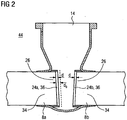
- Fig. 2 shows the shut-off valve 6 Fig. 1 with dismounted housing internals 32.
- the housing opening 14 is now open, that is, the interior of the housing 10 is accessible from the outside space 44.
- the sealing seats 24a, b are visible through the housing opening 14 and can be measured optically or with sliding calipers, not shown, or other measuring devices.
- the current state of the sealing seats 24a, b can be determined. In particular, it can be determined, for example, which thickness d the sealing seats 24a, b still have.
- the armor has 36 reduced from an original dashed line indicated thickness d 0 at the time of manufacture of the fitting 6 to the thickness d.
- a Clamping device 40 mounted in the connecting pipe 8a.
- the clamping device 40 is approximately disc-shaped and has a stop 42, with which it is placed on the sealing seat 24a.
- hydraulic cylinders 48 attached to the clamping device 40 are pressed against the inner wall 50 of the connecting pipe 8a.
- the hydraulic cylinder 48 is thus part of a fastening element, with which the clamping device 40 is fixed in the connecting pipe 8a.
- the clamping device 40 is securely fixed in the connecting pipe 8a.
- the clamping device 40 In order to center the radial position of the clamping device 40 in the connecting tube 8a exactly on its central longitudinal axis 52, the clamping device 40 also radially outwardly facing sensor 54, by which the distance of the clamping device 40 to the inner wall 50 at the respective position of the sensor 54 are measured can.
- the hydraulic cylinders 48 are driven accordingly to finally center the tensioning device 40.
- Fig. 3 shows the clamping device 40 in the final adjusted mounting state M.
- the tensioning device 40 has an abutment 56 which lies in the assembled state M in the interior of the housing 10 or points there and is accessible from the housing opening 14 forth.
- a reference point 57 namely the center of the thrust bearing 56 lies on the central longitudinal axis 52. This serves as a fixed geometric starting position for the bearing 64 to be attached as described below.
- a processing machine 58 is now likewise introduced through the housing opening 14 into the housing 10 in the direction of the arrow 38.
- the processing machine 58 is in Fig. 3 a lathe, which has a shaft arm 62 as the base support 60. On the base support 60 to the abutment 56 matching bearing 64 is firmly attached.
- Fig. 3 shows the processing machine 58 also in the assembled state M, namely, when the bearing 64 is inserted into the abutment 56 and stored in this.
- a drive 66 is attached, at the opposite end of the shaft arm 62, a machining head 68.
- the machining head 68 is rotatable about an axis of rotation 74 which to the longitudinal axis 76 of the shaft arm 62 a fixed , in the example has a 90 ° angle.
- a turning tool 78 is held as a machining tool or tool, which is deliverable relative to the shaft arm 62 only in the radial direction 80 and in the axial direction 82 with respect to the axis of rotation 74. This is achieved by a set screw 84 and a slide valve 86th
- the processing machine 58 is fixed or mounted on the housing 10 by the bearing 64 via the abutment 56 and the tensioning device 40 and is pivotable only in accordance with the degree of freedom permitted by the bearing 64 and abutment 56. On the other hand, it is stored at another point.
- a holder 70 is screwed, on which in turn adjustably a carriage 72 is mounted, which guides the shaft arm 62.
- the sealing seat 24b is to be machined such that its plane plane 88 assumes a predetermined angle ⁇ relative to the center plane 90 of the fitting 6, since the shut-off fitting 6 is a wedge slide.
- the processing machine 58 is to be set against the connection pipe 8b accordingly. Since the rotation axis 74 is fixed to the longitudinal axis 76, is the angle ⁇ is adjusted by moving the carriage 72 in the direction of the arrow 92, and so the shaft arm 62 is tilted in the abutment 56. The correct angle ⁇ is controlled by an inclinometer 94 mounted on the shaft arm 62.
- a processing step B1 is now carried out on the sealing seat 24b.
- the turning tool 78 in the radial direction 80 and axial direction 82 namely the remaining armor 36 of the thickness d is turned off from the connecting pipe 8b.
- the base material 34 is accessible again for a stable subsequent welding.
- a step e) the processing machine 58 is now released from the abutment 56 and removed through the housing opening 14 against the direction of the arrow 38 from the shut-off valve 6. Since the refurbishment of the sealing seat 24b has not yet been completed, the steps c) to e) are repeated in a step f) correspondingly often with changing processing machines 58.
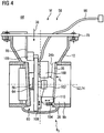
- FIG. 4 Now another processing machine 58 in the form of a TIG orbital welding machine is inserted through the housing opening 14 in the housing 10 in the direction of arrow 38.
- the processing machine 58 has again at its base support 60, a bearing 64 with which it is mounted in the abutment 56.
- the base support 60 is again fixed to the bracket 70 to fix the processing machine 58 in its mounting position M. This is done via a fixing arm 95.
- the base support 60 is connected to a supply module 98 arranged in the outer space 44. This contains eg the power source and the controller for the welder.
- a weldment 100 in the form of a wire roll, a wire feed 102 and a TIG welding torch 104 is arranged on the base support 60.
- the TIG welding torch 104 Via a rotary drive 106 and a radial slide 108 and an axial slide 110, the TIG welding torch 104 is always automatically held at the correct distance from the object to be welded, namely the end 26 of the connecting pipe 8b.
- processing step B2 a new armor 36 (indicated by dashed lines) welded onto the connecting pipe 8b.
- the processing step B2 ends when the armor 36 has reached the original thickness d 0 with a certain post-processing projection.
- the processing machine 58 is then removed from the housing 10 against the direction of the arrow 38.
- the clamping device 40 is now inserted into the already processed connecting pipe 8b and restored in the manner described above, the sealing seat 24a on its original dimension of the thickness d 0 .
- Fig. 5 shows as an alternative shut-off valve 6 a high-pressure slide, which also has a housing 10 and connecting pipes 8a, b, a sealing element 22, a spindle 18, a hand wheel 20 and a housing cover 16.
- a seat ring 114a, b is welded to the end 26 of the connecting pipes 8a, b respectively facing the interior of the housing 10. This carries in each case the sealing seat 24a, b.
- the restoration again includes the same steps as above.
- the sealing seats 24a, b are not restored on site, but removed together with their seat rings 114a, b from the valve 6 and restored outside or exchanged.
- the restored or new seat rings 114a, b are then re-welded.
- a clamping device 40 is completely spent in the interior of the connecting pipe 8a, which is equipped with hydraulic cylinders 48 and sensors 58 in order to be centered and fixed to the central longitudinal axis 52.
- a processing machine 58 is also introduced again in the direction of the arrow 38 in the interior of the housing 10 or in the present case also in the interior of the connecting pipe 8a.
- the tensioning device is held in the same connection tube whose sealing seat is also to be restored.
- Fig. 6 shows detail VI Fig. 5 ,
- the seat ring 114a which is connected via a weld 116 to the housing 10 or the connection pipe 8a, can be seen.
- the clamping device 40 is supported by the hydraulic cylinders 48 on the inner wall 50 of the connecting pipe 8a.
- the processing machine 58 is held with its bearing 64.
- the processing machine 58 is again a lathe with a turning tool 78 as a tool, which now separates the weld 116.
- the seat ring 114a may then be released and removed through the housing opening 14.
- the processing machine 58 is then replaced by a welding unit or machine, not shown, in the form of an alternative processing machine 58, which has a new seat ring 114a or a restored seat ring 114a in the in Fig. 6 welded in again shown original state.
- the holder 40 remains permanently clamped during all processing steps and thus forms with their abutment 56 a reference position for docking machine tools 58 to match the corresponding processing steps geometrically exactly to each other.
- a degassing slot 118 (in FIG Fig. 6 dashed indicated) present, in order to divert emerging welding gas during processing.
- Fig. 6 also shows how in a high-pressure sealing seat it is applied in the form of a multi-layer armor 36 on the seat ring 114a and not directly on the base material 34 of the housing 10 or connecting tube 8a.
Landscapes
- Engineering & Computer Science (AREA)
- Mechanical Engineering (AREA)
- Turning (AREA)
- Electrical Discharge Machining, Electrochemical Machining, And Combined Machining (AREA)
- Grinding And Polishing Of Tertiary Curved Surfaces And Surfaces With Complex Shapes (AREA)
- Pipe Accessories (AREA)
- Arc Welding In General (AREA)
- Automatic Assembly (AREA)
- Lift Valve (AREA)
Claims (18)
- Procédé pour l'usinage d'un siège d'étanchéité (24a,b) disposé à l'extrémité (26) d'un tube de raccordement (8a,b) d'un robinet d'arrêt (6) monté dans une centrale ou une installation industrielle (2), comprenant les étapes suivantes :a) la partie supérieure de robinet (16) et les éléments encastrés dans le boîtier (32) sont enlevés du boîtier (10) du robinet d'arrêt (6), ce qui libère une ouverture de boîtier (14),b) un dispositif de serrage (40) présentant un contre-palier (56) est introduit à travers l'ouverture de boîtier (14) dans le tube de raccordement ou dans un tube de raccordement supplémentaire (8a,b), et est fixé au niveau de sa paroi intérieure (50) de telle sorte que le dispositif de serrage (40) ou le contre-palier (56) forment dans le robinet d'arrêt (6) un lieu de référence fixé en position géométrique exacte,c) une machine d'usinage (58) présentant un palier (64) est introduite à travers l'ouverture de boîtier (14) dans le boîtier (10) et est supportée avec son palier (64) sur le contre-palier (56),d) une étape d'usinage (B1-4) est effectuée avec la machine d'usinage (58) sur le siège d'étanchéité (24a,b),e) la machine d'usinage (58) est séparée du contre-palier (56) et est enlevée à travers l'ouverture de boîtier (14),f) au besoin, les étapes c) à e) sont répétées avec une autre ou la même machine d'usinage (58),g) le dispositif de serrage (40) est séparé du tube de raccordement (8a,b) et est enlevé à travers l'ouverture de boîtier (14),h) la partie supérieure de robinet (16) et les éléments encastrés (32) sont montés sur le boîtier (10).
- Procédé selon la revendication 1, dans lequel, en tant qu'étape d'usinage (B1-4), le côté frontal du tube de raccordement (8a,b) tourné vers l'intérieur du boîtier (10) est enlevé par torsion ou par ponçage.
- Procédé selon l'une quelconque des revendications précédentes, dans lequel, en tant qu'étape d'usinage (B1-4), un blindage (36) formant le siège d'étanchéité (24a,b) est soudé sur le côté frontal du tube de raccordement (8a,b).
- Procédé selon l'une quelconque des revendications précédentes, dans lequel, en tant qu'étape d'usinage (B1-4), une bague de siège de boîtier (114a,b) portant le siège d'étanchéité (24a,b) est séparée du tube de raccordement (8a,b) ou est soudée à celui-ci.
- Procédé selon l'une quelconque des revendications précédentes, dans lequel le dispositif de serrage (40) est introduit dans le tube de raccordement (8a,b) jusqu'à ce qu'il vienne s'appliquer avec une butée (42) contre le côté frontal du tube de raccordement (8a,b) tourné vers l'intérieur du boîtier (10).
- Procédé selon l'une quelconque des revendications précédentes, dans lequel le dispositif de serrage (40) est fixé dans le tube de raccordement (8a,b) de telle sorte qu'un point de référence (57) du dispositif de serrage (40) soit situé sur l'axe longitudinal médian (52) du tube de raccordement (8a,b).
- Dispositif pour l'usinage d'un siège d'étanchéité (24a,b) disposé à l'extrémité (26) d'un tube de raccordement (8a,b) d'un robinet d'arrêt (6) monté dans une centrale ou une installation industrielle (2),- comprenant un dispositif de serrage (40) pouvant être introduit à travers une ouverture de boîtier (14) du robinet d'arrêt (6) dans le tube de raccordement ou dans un tube de raccordement supplémentaire (8a,b), lequel dispositif de serrage contient un contre-palier (56) et un élément de fixation (47) coopérant avec la paroi interne (50) du tube de raccordement (8a,b), le dispositif de serrage (40) ou le contre-palier (56) formant un lieu de référence fixé en position géométrique exacte dans le robinet d'arrêt (6),- comprenant au moins une machine d'usinage (58) pouvant être introduite à travers l'ouverture de boîtier (14) dans le boîtier pour mettre en oeuvre une étape d'usinage (B1-4) sur le siège d'étanchéité (24a,b), la machine d'usinage (58) présentant un palier (64) qui peut être supporté dans le contre-palier (56).
- Dispositif selon la revendication 7, dans lequel l'élément de fixation (47) contient un cylindre hydraulique (48) pouvant être approché contre la paroi intérieure (50) du tube de raccordement (8a,b).
- Dispositif selon l'une quelconque des revendications 7 à 8, dans lequel le dispositif de serrage (40) présente au moins deux palpeurs de mesure (54) pouvant être appliqués au niveau du côté intérieur (50) du tube de raccordement (8a,b).
- Dispositif selon l'une quelconque des revendications 7 à 9, dans lequel le contre-palier (56) est un logement à serrage rapide fixable et/ou le palier (64) est une tête de rouleau ou une tête sphérique.
- Dispositif selon l'une quelconque des revendications 7 à 10, dans lequel le contre-palier (56) est disposé fixement sur le dispositif de serrage (40), de telle sorte qu'il puisse être centré par un ajustement du dispositif de serrage (40) dans le tube de raccordement (8a,b) sur son axe longitudinal médian (52).
- Dispositif selon l'une quelconque des revendications 7 à 11, dans lequel la machine d'usinage (58) présente un support de base (60) rigide, faisant saillie hors de l'ouverture de boîtier (14) dans l'état monté (M), portant le palier (64), et une tête d'usinage (68) montée fixement sur celui-ci, par rapport à son inclinaison vers le siège d'étanchéité (24a,b), de telle sorte qu'une variation de l'angle d'inclinaison (α) de la tête d'usinage (68) par rapport à un plan médian (90) du robinet d'arrêt (6) soit provoquée par un basculement du support de base (60) dans le contre-palier (56).
- Dispositif selon la revendication 12, dans lequel la machine d'usinage (58) est une machine de tournage ou de meulage, avec un entraînement (66) situé à l'extérieur du boîtier (10) dans l'état monté (M), et avec un bras d'arbre (62) s'étendant depuis l'entraînement (66) jusqu'à une tête de travail (68), formant le support de base (60), la tête d'usinage (68) comprenant un élément de tournage (78) ou de meulage (112) pouvant tourner autour d'un axe de rotation (74) et l'axe de rotation (74) présentant une position relative fixe par rapport au bras d'arbre (62).
- Dispositif selon la revendication 13, dans lequel l'élément de tournage (78) ou de meulage (112) peut être avancé seulement dans la direction radiale (80) et axiale (82) par rapport à l'axe de rotation (74).
- Dispositif selon l'une quelconque des revendications 7 à 14, dans lequel la machine d'usinage (58) est une machine de soudage avec une unité d'alimentation (98) située dans l'état monté (M) à l'extérieur du boîtier (10), et un support de base (60) situé à l'intérieur du boîtier (10), présentant le palier (64), sur lequel sont disposés un récipient pour la soudure (100) et une tête de soudage (104) pouvant tourner autour d'un axe de rotation (74).
- Dispositif selon la revendication 15, dans lequel la machine de soudage est une machine de soudage orbital MIG.
- Dispositif selon l'une quelconque des revendications 7 à 16, dans lequel la machine d'usinage (58) comprend une fixation (70, 95) pouvant être fixée à l'ouverture de boîtier (14).
- Dispositif selon la revendication 17, dans lequel la fixation (70, 95), dans l'état monté (M) de la machine d'usinage (58), permet une variation et une fixation de la position de la machine d'usinage (58) dans le contre-palier (56).
Applications Claiming Priority (2)
| Application Number | Priority Date | Filing Date | Title |
|---|---|---|---|
| DE200910046401 DE102009046401B4 (de) | 2009-11-04 | 2009-11-04 | Verfahren und Vorrichtung zur Bearbeitung eines Dichtsitzes einer Absperrarmatur |
| PCT/EP2010/066780 WO2011054891A1 (fr) | 2009-11-04 | 2010-11-04 | Procédé et dispositif permettant l'usinage d'un siège d'étanchéité d'un robinet d'arrêt |
Publications (3)
| Publication Number | Publication Date |
|---|---|
| EP2496383A1 EP2496383A1 (fr) | 2012-09-12 |
| EP2496383B1 EP2496383B1 (fr) | 2017-01-04 |
| EP2496383B9 true EP2496383B9 (fr) | 2017-04-05 |
Family
ID=43734052
Family Applications (1)
| Application Number | Title | Priority Date | Filing Date |
|---|---|---|---|
| EP10779273.1A Active EP2496383B9 (fr) | 2009-11-04 | 2010-11-04 | Procédé et dispositif permettant l'usinage d'un siège d'étanchéité d'un robinet d'arrêt |
Country Status (10)
| Country | Link |
|---|---|
| US (1) | US8539673B2 (fr) |
| EP (1) | EP2496383B9 (fr) |
| JP (1) | JP5499178B2 (fr) |
| CN (1) | CN102596502B (fr) |
| BR (1) | BR112012010574B1 (fr) |
| CA (1) | CA2778164C (fr) |
| DE (1) | DE102009046401B4 (fr) |
| PL (1) | PL2496383T3 (fr) |
| RU (1) | RU2521569C2 (fr) |
| WO (1) | WO2011054891A1 (fr) |
Families Citing this family (17)
| Publication number | Priority date | Publication date | Assignee | Title |
|---|---|---|---|---|
| CN103737454A (zh) * | 2013-11-29 | 2014-04-23 | 成都欧浦特控制阀门有限公司 | 可定位的阀门研磨装置 |
| DE102014212149A1 (de) * | 2014-06-25 | 2015-12-31 | Siemens Aktiengesellschaft | Vorrichtung zur Verspreizung in einem Hohlraum und Verfahren zur Montage der Vorrichtung |
| RU2604238C2 (ru) * | 2015-02-05 | 2016-12-10 | Федеральное государственное бюджетное образовательное учреждение высшего профессионального образования "Липецкий государственный технический университет" (ЛГТУ) | Устройство для калибрования посадочных отверстий с полимерным покрытием в корпусных деталях |
| JP5881884B1 (ja) * | 2015-06-16 | 2016-03-09 | 三菱日立パワーシステムズ株式会社 | 弁座加工機および当該弁座加工機を用いた弁座加工方法 |
| JP5881883B1 (ja) * | 2015-06-16 | 2016-03-09 | 三菱日立パワーシステムズ株式会社 | 弁座加工機および当該弁座加工機を用いた弁座加工方法 |
| JP6335147B2 (ja) * | 2015-08-18 | 2018-05-30 | 日立Geニュークリア・エナジー株式会社 | ゲート弁シートリング摺り合わせ工具及びそれを用いたシートリングのメンテナンス方法 |
| CN106392881B (zh) * | 2016-10-25 | 2018-08-21 | 中国兵器科学研究院宁波分院 | 用于发动机一体式气门座圈巡边磨削加工的径向进给装置 |
| CN107030446B (zh) * | 2017-04-27 | 2023-01-31 | 上海电力股份有限公司吴泾热电厂 | 高温高压蒸汽阀门密封面在线修复系统 |
| RU2666973C1 (ru) * | 2017-10-13 | 2018-09-13 | Публичное акционерное общество "Транснефть" (ПАО "Транснефть") | Способ диагностики уплотнительных поверхностей запорной арматуры |
| CN107971729B (zh) * | 2017-12-25 | 2024-09-24 | 重庆众颖熙科技有限公司 | 一种用于压装缸盖导管与座圈的压装设备 |
| CN113714538B (zh) * | 2021-09-30 | 2022-07-01 | 浙江万得凯流体设备科技股份有限公司 | 一种截止阀的生产工艺 |
| CN115446335B (zh) * | 2022-08-18 | 2024-07-16 | 中核核电运行管理有限公司 | 一种用于主蒸汽安全阀在线加工的模块化机床 |
| CN116652500B (zh) * | 2023-06-20 | 2024-05-31 | 黄山市海纳智能制造有限公司 | 阀座加工用法兰盘与座体拼焊平台 |
| CN117140198B (zh) * | 2023-08-22 | 2025-10-31 | 吉林市佰丰科技有限公司 | 一种核电阀门智能化打磨检测系统 |
| CN118417994B (zh) * | 2023-11-22 | 2024-10-08 | 温州弘球机械有限公司 | 一种硬密封球阀阀体与密封座快速配磨装备及工艺 |
| CN117718683A (zh) * | 2023-12-08 | 2024-03-19 | 中船澄西船舶修造有限公司 | 一种喷油器与汽缸盖接触面修复方法 |
| CN120828285B (zh) * | 2025-09-17 | 2026-01-06 | 高特控股集团有限公司 | 一种截止阀的自动化组装系统及其工作方法 |
Family Cites Families (18)
| Publication number | Priority date | Publication date | Assignee | Title |
|---|---|---|---|---|
| DE2400077A1 (de) * | 1974-01-02 | 1975-07-17 | Alfred Butz | Vorrichtung zum schleifen von flaechen, insbesondere von dichtungsflaechen fuer absperrschieber oder dergleichen |
| US3881396A (en) * | 1974-03-01 | 1975-05-06 | Grimsley Ernest E | Portable boring bar |
| DD109822A1 (fr) * | 1974-03-21 | 1974-11-20 | ||
| JPS5246521A (en) * | 1975-10-13 | 1977-04-13 | Okano Valve Seizo Kk | Self valve seat lapping device for sluice valve |
| US4000584A (en) * | 1976-04-01 | 1977-01-04 | The United States Of America As Represented By The Secretary Of The Navy | In-situ lapping apparatus for gate valves |
| FI59292C (fi) * | 1979-04-18 | 1981-07-10 | Waertsilae Oy Ab | Slidventil |
| DE3237902A1 (de) * | 1982-10-13 | 1984-04-19 | Bernd Dipl.-Ing. 5620 Velbert Kirchner | Flanschschleifmaschine |
| DD217171A1 (de) * | 1983-09-09 | 1985-01-09 | Orgreb Inst Kraftwerke | Einrichtung zur messung der anpresskraft des werkzeuges einer transportablen dichtflaechenschleifmaschine |
| DE8706117U1 (de) * | 1987-04-28 | 1987-06-11 | Unislip GmbH, 5180 Eschweiler | Andrückvorrichtung für Schieberschleifmaschinen |
| DD278542A1 (de) * | 1988-12-23 | 1990-05-09 | Magdeburger Armaturenwerke | Vorrichtung zum feinstschleifen von schiebergehaeusedichtflaechen |
| JPH03116107A (ja) * | 1989-09-29 | 1991-05-17 | Sumitomo Electric Ind Ltd | 光通信器 |
| US5732607A (en) * | 1995-05-12 | 1998-03-31 | Climax Portable Machine Tools, Inc. | Portable machine tool |
| US6007410A (en) * | 1998-08-07 | 1999-12-28 | Nerenberg; Bruno | Pipefacing tool |
| RU17297U1 (ru) * | 1999-10-05 | 2001-03-27 | Ооо "Экосервис" | Устройство для электродуговой наплавки |
| DE102005004232A1 (de) * | 2005-01-28 | 2006-08-10 | Ksc Kraftwerks-Service Cottbus Anlagenbau Gmbh, Sitz Peitz | Verfahren und Vorrichtung insbesondere zur Reparatur von Absperrarmaturen in Kraftwerken |
| RU46696U1 (ru) * | 2005-02-22 | 2005-07-27 | Общество с ограниченной ответственностью "Томскнефтехим" (ООО "Томскнефтехим") | Переносной станок для механической обработки уплотнительных поверхностей седел клиновых и шиберных задвижек без удаления их с трубопроводов |
| CN2827630Y (zh) * | 2005-07-06 | 2006-10-18 | 范金娥 | 一种阀门研磨机 |
| CN101176981A (zh) * | 2007-11-02 | 2008-05-14 | 赵殿纯 | 砂轮研磨机在阀门上的应用研磨方法 |
-
2009
- 2009-11-04 DE DE200910046401 patent/DE102009046401B4/de not_active Expired - Fee Related
-
2010
- 2010-11-04 PL PL10779273T patent/PL2496383T3/pl unknown
- 2010-11-04 EP EP10779273.1A patent/EP2496383B9/fr active Active
- 2010-11-04 WO PCT/EP2010/066780 patent/WO2011054891A1/fr not_active Ceased
- 2010-11-04 JP JP2012535879A patent/JP5499178B2/ja not_active Expired - Fee Related
- 2010-11-04 BR BR112012010574-4A patent/BR112012010574B1/pt not_active IP Right Cessation
- 2010-11-04 CA CA2778164A patent/CA2778164C/fr not_active Expired - Fee Related
- 2010-11-04 RU RU2012122829/02A patent/RU2521569C2/ru active
- 2010-11-04 CN CN201080049996.5A patent/CN102596502B/zh not_active Expired - Fee Related
-
2012
- 2012-05-04 US US13/463,985 patent/US8539673B2/en not_active Expired - Fee Related
Also Published As
| Publication number | Publication date |
|---|---|
| US8539673B2 (en) | 2013-09-24 |
| EP2496383B1 (fr) | 2017-01-04 |
| EP2496383A1 (fr) | 2012-09-12 |
| US20120240403A1 (en) | 2012-09-27 |
| WO2011054891A1 (fr) | 2011-05-12 |
| CA2778164C (fr) | 2015-11-03 |
| RU2012122829A (ru) | 2013-12-10 |
| PL2496383T3 (pl) | 2017-09-29 |
| DE102009046401B4 (de) | 2012-08-09 |
| RU2521569C2 (ru) | 2014-06-27 |
| JP5499178B2 (ja) | 2014-05-21 |
| BR112012010574A2 (pt) | 2016-03-22 |
| DE102009046401A1 (de) | 2011-05-12 |
| JP2013510008A (ja) | 2013-03-21 |
| CN102596502A (zh) | 2012-07-18 |
| CA2778164A1 (fr) | 2011-05-12 |
| CN102596502B (zh) | 2015-10-14 |
| BR112012010574B1 (pt) | 2021-01-05 |
Similar Documents
| Publication | Publication Date | Title |
|---|---|---|
| EP2496383B9 (fr) | Procédé et dispositif permettant l'usinage d'un siège d'étanchéité d'un robinet d'arrêt | |
| DE102006037490B4 (de) | Doppelseiten-Bearbeitungsmaschine | |
| DE102009051737B3 (de) | Verfahren zum Schleifen der Haupt- und Hublager einer Kurbelwelle durch Aussenrundschleifen und Schleifmaschine zum Durchführen des Verfahrens | |
| DE102007034706B3 (de) | Schleifzentrum und Verfahren zum gleichzeitigen Schleifen mehrerer Lager und endseitigen Flächen von Kurbelwellen | |
| DE102007061542A1 (de) | Verfahren und Vorrichtung zur Bearbeitung von Kaplanturbinenschaufeln | |
| EP2708324B1 (fr) | Plaque de table pour table à butée de ressort d'une rectifieuse pour ressorts et rectifieuse à ressorts dotée de celle-ci | |
| EP1588224B1 (fr) | Procede et dispositif de fabrication d'aubes de service | |
| EP3116683A1 (fr) | Procédé et dispositif de rectification de grands vilebrequins | |
| WO2011124499A1 (fr) | Mandrin de serrage pour machines d'usinage de tubes, et procédé de contrôle correspondant | |
| WO2017211452A1 (fr) | Machine d'usinage de pièces de qualité optique | |
| EP2414134B1 (fr) | Dispositif et procédé de découpe au jet d'eau | |
| DE102013225292A1 (de) | Lünette zum abstützen von zentrischen werkstückbereichen während der bearbeitung von zentrischen und/oder exzentrischen werkstückbereichen insbesondere lagerstellen an kurbelwellen sowie schleifmaschine mit einer derartigen lünette | |
| WO2009146715A1 (fr) | Dispositif d’élargissement de boîte et procédé permettant de forger une ébauche de boîte | |
| EP2087956A1 (fr) | Procédé et machine de traitement destinée au traitement tendu de contours complexes de pièces usinées asymétriques | |
| DE102010010431B4 (de) | Verfahren zur Wiederaufarbeitung der verschlissenen Oberfläche von Mahlwalzen einer Gutbettwalzenmühle | |
| DE102014225295A1 (de) | Mess-lünette zum abstützen und vermessen von zentrischen werkstückbereichen, schleifmaschine mit einer derartigen mess-lünette sowie verfahren zum abstützen und vermessen von zentrischen werstückbereichen | |
| DE102015220525B4 (de) | Vorrichtung und Verfahren zur Bearbeitung eines Bauteils | |
| DE2336809B2 (de) | Maschine zum Lichtbogen-Schmelzschweissen von Rohr-Stumpfstößen in horizontaler Schweißnaht-Ebene | |
| DE202007000535U1 (de) | Gewichtsführungs- und Regelungssystem | |
| DE102005004232A1 (de) | Verfahren und Vorrichtung insbesondere zur Reparatur von Absperrarmaturen in Kraftwerken | |
| EP0309513B1 (fr) | Systeme de broches pour machines-outils, en particulier meuleuses | |
| DE102010053405B4 (de) | Verfahren und Schleifmaschine zum Außenschleifen von stabförmigen Werkstücken | |
| DE102012108628B3 (de) | Vorrichtung zum Bearbeiten von Werkstücken mit integrierter Werkzeug-Abrichteinheit | |
| DE10237375A1 (de) | Vorrichtung und Verfahren zur geometrischen Vermessung eines im Querschnitt kreisförmigen Rohres | |
| DE602005004302T2 (de) | Verdichter und Verfahren zur Wiederherstellung eines Verdichters |
Legal Events
| Date | Code | Title | Description |
|---|---|---|---|
| PUAI | Public reference made under article 153(3) epc to a published international application that has entered the european phase |
Free format text: ORIGINAL CODE: 0009012 |
|
| 17P | Request for examination filed |
Effective date: 20120403 |
|
| AK | Designated contracting states |
Kind code of ref document: A1 Designated state(s): AL AT BE BG CH CY CZ DE DK EE ES FI FR GB GR HR HU IE IS IT LI LT LU LV MC MK MT NL NO PL PT RO RS SE SI SK SM TR |
|
| DAX | Request for extension of the european patent (deleted) | ||
| RAP1 | Party data changed (applicant data changed or rights of an application transferred) |
Owner name: AREVA GMBH |
|
| GRAP | Despatch of communication of intention to grant a patent |
Free format text: ORIGINAL CODE: EPIDOSNIGR1 |
|
| INTG | Intention to grant announced |
Effective date: 20151113 |
|
| GRAP | Despatch of communication of intention to grant a patent |
Free format text: ORIGINAL CODE: EPIDOSNIGR1 |
|
| INTG | Intention to grant announced |
Effective date: 20160624 |
|
| GRAS | Grant fee paid |
Free format text: ORIGINAL CODE: EPIDOSNIGR3 |
|
| GRAA | (expected) grant |
Free format text: ORIGINAL CODE: 0009210 |
|
| RAP1 | Party data changed (applicant data changed or rights of an application transferred) |
Owner name: WURZER, VOLKER |
|
| AK | Designated contracting states |
Kind code of ref document: B1 Designated state(s): AL AT BE BG CH CY CZ DE DK EE ES FI FR GB GR HR HU IE IS IT LI LT LU LV MC MK MT NL NO PL PT RO RS SE SI SK SM TR |
|
| REG | Reference to a national code |
Ref country code: GB Ref legal event code: FG4D Free format text: NOT ENGLISH |
|
| REG | Reference to a national code |
Ref country code: CH Ref legal event code: EP |
|
| REG | Reference to a national code |
Ref country code: AT Ref legal event code: REF Ref document number: 858775 Country of ref document: AT Kind code of ref document: T Effective date: 20170115 |
|
| REG | Reference to a national code |
Ref country code: IE Ref legal event code: FG4D Free format text: LANGUAGE OF EP DOCUMENT: GERMAN |
|
| GRAT | Correction requested after decision to grant or after decision to maintain patent in amended form |
Free format text: ORIGINAL CODE: EPIDOSNCDEC |
|
| REG | Reference to a national code |
Ref country code: DE Ref legal event code: R096 Ref document number: 502010013003 Country of ref document: DE |
|
| RAP2 | Party data changed (patent owner data changed or rights of a patent transferred) |
Owner name: WURZER, VOLKER |
|
| REG | Reference to a national code |
Ref country code: SE Ref legal event code: TRGR |
|
| REG | Reference to a national code |
Ref country code: LT Ref legal event code: MG4D Ref country code: NL Ref legal event code: MP Effective date: 20170104 |
|
| PG25 | Lapsed in a contracting state [announced via postgrant information from national office to epo] |
Ref country code: NL Free format text: LAPSE BECAUSE OF FAILURE TO SUBMIT A TRANSLATION OF THE DESCRIPTION OR TO PAY THE FEE WITHIN THE PRESCRIBED TIME-LIMIT Effective date: 20170104 |
|
| PG25 | Lapsed in a contracting state [announced via postgrant information from national office to epo] |
Ref country code: HR Free format text: LAPSE BECAUSE OF FAILURE TO SUBMIT A TRANSLATION OF THE DESCRIPTION OR TO PAY THE FEE WITHIN THE PRESCRIBED TIME-LIMIT Effective date: 20170104 Ref country code: LT Free format text: LAPSE BECAUSE OF FAILURE TO SUBMIT A TRANSLATION OF THE DESCRIPTION OR TO PAY THE FEE WITHIN THE PRESCRIBED TIME-LIMIT Effective date: 20170104 Ref country code: NO Free format text: LAPSE BECAUSE OF FAILURE TO SUBMIT A TRANSLATION OF THE DESCRIPTION OR TO PAY THE FEE WITHIN THE PRESCRIBED TIME-LIMIT Effective date: 20170404 Ref country code: IS Free format text: LAPSE BECAUSE OF FAILURE TO SUBMIT A TRANSLATION OF THE DESCRIPTION OR TO PAY THE FEE WITHIN THE PRESCRIBED TIME-LIMIT Effective date: 20170504 Ref country code: GR Free format text: LAPSE BECAUSE OF FAILURE TO SUBMIT A TRANSLATION OF THE DESCRIPTION OR TO PAY THE FEE WITHIN THE PRESCRIBED TIME-LIMIT Effective date: 20170405 |
|
| PG25 | Lapsed in a contracting state [announced via postgrant information from national office to epo] |
Ref country code: RS Free format text: LAPSE BECAUSE OF FAILURE TO SUBMIT A TRANSLATION OF THE DESCRIPTION OR TO PAY THE FEE WITHIN THE PRESCRIBED TIME-LIMIT Effective date: 20170104 Ref country code: LV Free format text: LAPSE BECAUSE OF FAILURE TO SUBMIT A TRANSLATION OF THE DESCRIPTION OR TO PAY THE FEE WITHIN THE PRESCRIBED TIME-LIMIT Effective date: 20170104 Ref country code: PT Free format text: LAPSE BECAUSE OF FAILURE TO SUBMIT A TRANSLATION OF THE DESCRIPTION OR TO PAY THE FEE WITHIN THE PRESCRIBED TIME-LIMIT Effective date: 20170504 Ref country code: ES Free format text: LAPSE BECAUSE OF FAILURE TO SUBMIT A TRANSLATION OF THE DESCRIPTION OR TO PAY THE FEE WITHIN THE PRESCRIBED TIME-LIMIT Effective date: 20170104 Ref country code: BG Free format text: LAPSE BECAUSE OF FAILURE TO SUBMIT A TRANSLATION OF THE DESCRIPTION OR TO PAY THE FEE WITHIN THE PRESCRIBED TIME-LIMIT Effective date: 20170404 |
|
| REG | Reference to a national code |
Ref country code: DE Ref legal event code: R097 Ref document number: 502010013003 Country of ref document: DE |
|
| PG25 | Lapsed in a contracting state [announced via postgrant information from national office to epo] |
Ref country code: EE Free format text: LAPSE BECAUSE OF FAILURE TO SUBMIT A TRANSLATION OF THE DESCRIPTION OR TO PAY THE FEE WITHIN THE PRESCRIBED TIME-LIMIT Effective date: 20170104 Ref country code: RO Free format text: LAPSE BECAUSE OF FAILURE TO SUBMIT A TRANSLATION OF THE DESCRIPTION OR TO PAY THE FEE WITHIN THE PRESCRIBED TIME-LIMIT Effective date: 20170104 Ref country code: SK Free format text: LAPSE BECAUSE OF FAILURE TO SUBMIT A TRANSLATION OF THE DESCRIPTION OR TO PAY THE FEE WITHIN THE PRESCRIBED TIME-LIMIT Effective date: 20170104 Ref country code: IT Free format text: LAPSE BECAUSE OF FAILURE TO SUBMIT A TRANSLATION OF THE DESCRIPTION OR TO PAY THE FEE WITHIN THE PRESCRIBED TIME-LIMIT Effective date: 20170104 |
|
| PLBE | No opposition filed within time limit |
Free format text: ORIGINAL CODE: 0009261 |
|
| STAA | Information on the status of an ep patent application or granted ep patent |
Free format text: STATUS: NO OPPOSITION FILED WITHIN TIME LIMIT |
|
| REG | Reference to a national code |
Ref country code: FR Ref legal event code: PLFP Year of fee payment: 8 |
|
| PG25 | Lapsed in a contracting state [announced via postgrant information from national office to epo] |
Ref country code: SM Free format text: LAPSE BECAUSE OF FAILURE TO SUBMIT A TRANSLATION OF THE DESCRIPTION OR TO PAY THE FEE WITHIN THE PRESCRIBED TIME-LIMIT Effective date: 20170104 Ref country code: DK Free format text: LAPSE BECAUSE OF FAILURE TO SUBMIT A TRANSLATION OF THE DESCRIPTION OR TO PAY THE FEE WITHIN THE PRESCRIBED TIME-LIMIT Effective date: 20170104 |
|
| 26N | No opposition filed |
Effective date: 20171005 |
|
| PG25 | Lapsed in a contracting state [announced via postgrant information from national office to epo] |
Ref country code: SI Free format text: LAPSE BECAUSE OF FAILURE TO SUBMIT A TRANSLATION OF THE DESCRIPTION OR TO PAY THE FEE WITHIN THE PRESCRIBED TIME-LIMIT Effective date: 20170104 |
|
| PG25 | Lapsed in a contracting state [announced via postgrant information from national office to epo] |
Ref country code: MC Free format text: LAPSE BECAUSE OF FAILURE TO SUBMIT A TRANSLATION OF THE DESCRIPTION OR TO PAY THE FEE WITHIN THE PRESCRIBED TIME-LIMIT Effective date: 20170104 |
|
| PG25 | Lapsed in a contracting state [announced via postgrant information from national office to epo] |
Ref country code: LU Free format text: LAPSE BECAUSE OF NON-PAYMENT OF DUE FEES Effective date: 20171104 |
|
| REG | Reference to a national code |
Ref country code: IE Ref legal event code: MM4A |
|
| PG25 | Lapsed in a contracting state [announced via postgrant information from national office to epo] |
Ref country code: MT Free format text: LAPSE BECAUSE OF FAILURE TO SUBMIT A TRANSLATION OF THE DESCRIPTION OR TO PAY THE FEE WITHIN THE PRESCRIBED TIME-LIMIT Effective date: 20170104 |
|
| PG25 | Lapsed in a contracting state [announced via postgrant information from national office to epo] |
Ref country code: IE Free format text: LAPSE BECAUSE OF NON-PAYMENT OF DUE FEES Effective date: 20171104 |
|
| REG | Reference to a national code |
Ref country code: AT Ref legal event code: MM01 Ref document number: 858775 Country of ref document: AT Kind code of ref document: T Effective date: 20171104 |
|
| PG25 | Lapsed in a contracting state [announced via postgrant information from national office to epo] |
Ref country code: AT Free format text: LAPSE BECAUSE OF NON-PAYMENT OF DUE FEES Effective date: 20171104 |
|
| PG25 | Lapsed in a contracting state [announced via postgrant information from national office to epo] |
Ref country code: HU Free format text: LAPSE BECAUSE OF FAILURE TO SUBMIT A TRANSLATION OF THE DESCRIPTION OR TO PAY THE FEE WITHIN THE PRESCRIBED TIME-LIMIT; INVALID AB INITIO Effective date: 20101104 |
|
| PG25 | Lapsed in a contracting state [announced via postgrant information from national office to epo] |
Ref country code: CY Free format text: LAPSE BECAUSE OF NON-PAYMENT OF DUE FEES Effective date: 20170104 |
|
| PG25 | Lapsed in a contracting state [announced via postgrant information from national office to epo] |
Ref country code: MK Free format text: LAPSE BECAUSE OF FAILURE TO SUBMIT A TRANSLATION OF THE DESCRIPTION OR TO PAY THE FEE WITHIN THE PRESCRIBED TIME-LIMIT Effective date: 20170104 |
|
| PG25 | Lapsed in a contracting state [announced via postgrant information from national office to epo] |
Ref country code: TR Free format text: LAPSE BECAUSE OF FAILURE TO SUBMIT A TRANSLATION OF THE DESCRIPTION OR TO PAY THE FEE WITHIN THE PRESCRIBED TIME-LIMIT Effective date: 20170104 |
|
| PG25 | Lapsed in a contracting state [announced via postgrant information from national office to epo] |
Ref country code: AL Free format text: LAPSE BECAUSE OF FAILURE TO SUBMIT A TRANSLATION OF THE DESCRIPTION OR TO PAY THE FEE WITHIN THE PRESCRIBED TIME-LIMIT Effective date: 20170104 |
|
| PGFP | Annual fee paid to national office [announced via postgrant information from national office to epo] |
Ref country code: CH Payment date: 20201118 Year of fee payment: 11 Ref country code: CZ Payment date: 20201103 Year of fee payment: 11 Ref country code: SE Payment date: 20201125 Year of fee payment: 11 Ref country code: FI Payment date: 20201119 Year of fee payment: 11 Ref country code: GB Payment date: 20201119 Year of fee payment: 11 Ref country code: FR Payment date: 20201120 Year of fee payment: 11 |
|
| PGFP | Annual fee paid to national office [announced via postgrant information from national office to epo] |
Ref country code: PL Payment date: 20201027 Year of fee payment: 11 Ref country code: BE Payment date: 20201125 Year of fee payment: 11 |
|
| REG | Reference to a national code |
Ref country code: CH Ref legal event code: PL |
|
| REG | Reference to a national code |
Ref country code: FI Ref legal event code: MAE |
|
| GBPC | Gb: european patent ceased through non-payment of renewal fee |
Effective date: 20211104 |
|
| PG25 | Lapsed in a contracting state [announced via postgrant information from national office to epo] |
Ref country code: SE Free format text: LAPSE BECAUSE OF NON-PAYMENT OF DUE FEES Effective date: 20211105 Ref country code: CZ Free format text: LAPSE BECAUSE OF NON-PAYMENT OF DUE FEES Effective date: 20211104 Ref country code: BE Free format text: LAPSE BECAUSE OF NON-PAYMENT OF DUE FEES Effective date: 20211130 |
|
| REG | Reference to a national code |
Ref country code: BE Ref legal event code: MM Effective date: 20211130 |
|
| PG25 | Lapsed in a contracting state [announced via postgrant information from national office to epo] |
Ref country code: LI Free format text: LAPSE BECAUSE OF NON-PAYMENT OF DUE FEES Effective date: 20211130 Ref country code: FI Free format text: LAPSE BECAUSE OF NON-PAYMENT OF DUE FEES Effective date: 20211104 Ref country code: CH Free format text: LAPSE BECAUSE OF NON-PAYMENT OF DUE FEES Effective date: 20211130 |
|
| PG25 | Lapsed in a contracting state [announced via postgrant information from national office to epo] |
Ref country code: GB Free format text: LAPSE BECAUSE OF NON-PAYMENT OF DUE FEES Effective date: 20211104 |
|
| PG25 | Lapsed in a contracting state [announced via postgrant information from national office to epo] |
Ref country code: FR Free format text: LAPSE BECAUSE OF NON-PAYMENT OF DUE FEES Effective date: 20211130 |
|
| PG25 | Lapsed in a contracting state [announced via postgrant information from national office to epo] |
Ref country code: PL Free format text: LAPSE BECAUSE OF NON-PAYMENT OF DUE FEES Effective date: 20211104 |
|
| P01 | Opt-out of the competence of the unified patent court (upc) registered |
Effective date: 20230414 |
|
| PGFP | Annual fee paid to national office [announced via postgrant information from national office to epo] |
Ref country code: DE Payment date: 20251119 Year of fee payment: 16 |