EP2496383B9 - Verfahren und vorrichtung zur bearbeitung eines dichtsitzes einer absperrarmatur - Google Patents
Verfahren und vorrichtung zur bearbeitung eines dichtsitzes einer absperrarmatur Download PDFInfo
- Publication number
- EP2496383B9 EP2496383B9 EP10779273.1A EP10779273A EP2496383B9 EP 2496383 B9 EP2496383 B9 EP 2496383B9 EP 10779273 A EP10779273 A EP 10779273A EP 2496383 B9 EP2496383 B9 EP 2496383B9
- Authority
- EP
- European Patent Office
- Prior art keywords
- housing
- valve
- connection pipe
- shut
- counterbearing
- Prior art date
- Legal status (The legal status is an assumption and is not a legal conclusion. Google has not performed a legal analysis and makes no representation as to the accuracy of the status listed.)
- Active
Links
Images


Classifications
-
- B—PERFORMING OPERATIONS; TRANSPORTING
- B24—GRINDING; POLISHING
- B24B—MACHINES, DEVICES, OR PROCESSES FOR GRINDING OR POLISHING; DRESSING OR CONDITIONING OF ABRADING SURFACES; FEEDING OF GRINDING, POLISHING, OR LAPPING AGENTS
- B24B15/00—Machines or devices designed for grinding seat surfaces; Accessories therefor
- B24B15/02—Machines or devices designed for grinding seat surfaces; Accessories therefor in valve housings
- B24B15/03—Machines or devices designed for grinding seat surfaces; Accessories therefor in valve housings using portable or mobile machines
-
- Y—GENERAL TAGGING OF NEW TECHNOLOGICAL DEVELOPMENTS; GENERAL TAGGING OF CROSS-SECTIONAL TECHNOLOGIES SPANNING OVER SEVERAL SECTIONS OF THE IPC; TECHNICAL SUBJECTS COVERED BY FORMER USPC CROSS-REFERENCE ART COLLECTIONS [XRACs] AND DIGESTS
- Y10—TECHNICAL SUBJECTS COVERED BY FORMER USPC
- Y10T—TECHNICAL SUBJECTS COVERED BY FORMER US CLASSIFICATION
- Y10T137/00—Fluid handling
- Y10T137/4238—With cleaner, lubrication added to fluid or liquid sealing at valve interface
- Y10T137/4245—Cleaning or steam sterilizing
- Y10T137/4273—Mechanical cleaning
- Y10T137/428—Valve grinding motion of valve on seat
-
- Y—GENERAL TAGGING OF NEW TECHNOLOGICAL DEVELOPMENTS; GENERAL TAGGING OF CROSS-SECTIONAL TECHNOLOGIES SPANNING OVER SEVERAL SECTIONS OF THE IPC; TECHNICAL SUBJECTS COVERED BY FORMER USPC CROSS-REFERENCE ART COLLECTIONS [XRACs] AND DIGESTS
- Y10—TECHNICAL SUBJECTS COVERED BY FORMER USPC
- Y10T—TECHNICAL SUBJECTS COVERED BY FORMER US CLASSIFICATION
- Y10T29/00—Metal working
- Y10T29/49—Method of mechanical manufacture
- Y10T29/49405—Valve or choke making
- Y10T29/49407—Repairing, converting, servicing or salvaging
-
- Y—GENERAL TAGGING OF NEW TECHNOLOGICAL DEVELOPMENTS; GENERAL TAGGING OF CROSS-SECTIONAL TECHNOLOGIES SPANNING OVER SEVERAL SECTIONS OF THE IPC; TECHNICAL SUBJECTS COVERED BY FORMER USPC CROSS-REFERENCE ART COLLECTIONS [XRACs] AND DIGESTS
- Y10—TECHNICAL SUBJECTS COVERED BY FORMER USPC
- Y10T—TECHNICAL SUBJECTS COVERED BY FORMER US CLASSIFICATION
- Y10T29/00—Metal working
- Y10T29/49—Method of mechanical manufacture
- Y10T29/49718—Repairing
- Y10T29/49719—Seal or element thereof
-
- Y—GENERAL TAGGING OF NEW TECHNOLOGICAL DEVELOPMENTS; GENERAL TAGGING OF CROSS-SECTIONAL TECHNOLOGIES SPANNING OVER SEVERAL SECTIONS OF THE IPC; TECHNICAL SUBJECTS COVERED BY FORMER USPC CROSS-REFERENCE ART COLLECTIONS [XRACs] AND DIGESTS
- Y10—TECHNICAL SUBJECTS COVERED BY FORMER USPC
- Y10T—TECHNICAL SUBJECTS COVERED BY FORMER US CLASSIFICATION
- Y10T29/00—Metal working
- Y10T29/49—Method of mechanical manufacture
- Y10T29/49718—Repairing
- Y10T29/49721—Repairing with disassembling
- Y10T29/49723—Repairing with disassembling including reconditioning of part
- Y10T29/49725—Repairing with disassembling including reconditioning of part by shaping
- Y10T29/49726—Removing material
- Y10T29/49728—Removing material and by a metallurgical operation, e.g., welding, diffusion bonding, casting
-
- Y—GENERAL TAGGING OF NEW TECHNOLOGICAL DEVELOPMENTS; GENERAL TAGGING OF CROSS-SECTIONAL TECHNOLOGIES SPANNING OVER SEVERAL SECTIONS OF THE IPC; TECHNICAL SUBJECTS COVERED BY FORMER USPC CROSS-REFERENCE ART COLLECTIONS [XRACs] AND DIGESTS
- Y10—TECHNICAL SUBJECTS COVERED BY FORMER USPC
- Y10T—TECHNICAL SUBJECTS COVERED BY FORMER US CLASSIFICATION
- Y10T82/00—Turning
- Y10T82/12—Radially moving rotating tool inside bore
- Y10T82/125—Tool simultaneously moving axially
Definitions
- the invention relates to a method and a device for processing a sealing seat of a shut-off valve.
- shut-off valves To shut off pipelines in power plants or industrial plants a variety of shut-off valves are used. As industrial plants come e.g. all fluid equipment, e.g. the chemical industry, in question. For power plants here are all types of power plants such. Nuclear power plants, i. Boiling and pressurized water reactors addressed.
- shut-off valves are e.g. Gate valves and check valves in low (ND), medium (MD) and high pressure (HD) areas, corresponding to approx. 40bar, 40-160bar and over 160bar.
- the nominal widths of corresponding shut-off valves are in the range of approx. 50 to 1200mm.
- the shut-off valves in this case have at least two connecting pipes, which lead into the interior of a valve body. There have such connection pipes with sealing functionality on their front ends sealing seats. These are e.g. parallel to the center plane of the shut-off valve (LP check valve) or in a plane inclined towards the upper part of the valve (HD gate valve).
- Sealing elements such as sealing plates driven into the region of the connecting pipes of the valve body, which bear against the sealing seat.
- Sealing elements such as sealing plates driven into the region of the connecting pipes of the valve body, which bear against the sealing seat.
- the pressure-loaded side (inlet connection pipe) of a gate valve presses the sealing plate against the sealing ring or sealing seat on the non-pressurized side (drain connection pipe). This creates a sealing effect.
- shut-off valves for example, the medium is thereby blocked independently of the direction of flow; in the case of check valves, the media flow is blocked only against a predetermined flow direction.
- Gate valves are usually set path-dependent via remote drives or handwheels.
- the path-dependence of the travel path means that the sealing plates are moved in and out of the valve housing just enough so that they reliably block or release the sealing seat even taking into account all the temperature expansions and do not collide with the valve body.
- shut-off valves Since the sealing surfaces in corresponding shut-off valves must withstand a high load, these are e.g. Low-pressure valves up to nominal pressure (PN, Pressure Nominal) PN40 secured against wear with a 17% chrome steel armor. In other words, a few millimeters thick layer of chromium steel is welded onto the front end of the connecting pipe as a hard application.
- PN Pressure Nominal
- shut-off valve or their seals with appropriate wear.
- the slide assemblies e.g. the sealing plates, gate valves, check valves, etc.
- the transport of the removed parts is usually unproblematic.
- the remediation can therefore be e.g. done locally in the plant outside the valve, in a workshop of the plant or at a manufacturer of the valve.
- the problem is the renovation of the sealing seats of the connection pipes. Access to the sealing seats within the fitting housing is limited.
- a method for regrinding the damaged sealing surfaces on site with the aid of so-called slider grinding machines, for example from the DD 217 171 A1 , of the DD 278 542 A1 , of the DE 24 00 077 A1 and the DD 109 822 A1 , In this case, the upper part of the valve and the internals are removed from the housing of the shut-off valve, whereby a housing opening will release. Through the housing opening, the grinder is manually inserted into the fitting housing and the existing sealing seat reground.
- the damage is remedied by separating the entire shut-off valve from the piping system.
- the segregated fitting is then provided for refurbishment in a site workshop or to the valve manufacturer, which have the necessary refurbishment machines.
- the fitting is then clamped in its entirety on the outer surfaces in a jig and through conventional processing machines, such as lathes, welding machines, etc. rehabilitated.
- the defective valve is not rehabilitated, but disposed of and introduced at the original point of the pipe system in the power plant or industrial plant a new or replacement fitting.
- the removal and re-welding of a valve is associated with considerable costs.
- extensive repair specifications are necessary especially for nuclear power plants.
- the separation of large and heavy valves from the existing pipe system requires special equipment, special lifting equipment and is often only possible with considerable effort due to the tight environmental space of the valve, since e.g. initially surrounding installation or building parts must be removed in order to remove the fitting at all.
- valves are contaminated, which leads to additional effort and costs.
- the handling when removing the fittings is associated with increased risk of injury to the people involved and the risk of damaging the shut-off itself or other components of the industrial plant.
- make compensating tubes as the heat-affected zones must be completely eliminated and cutting losses must be compensated.
- the installation position of the valve must be restored to its original state. If a new shut-off valve is used, a significantly increased planning effort is to be expected, since current regulations, such as the Pressure Equipment Directive, must be taken into account for the new valve are.
- the object of the invention is therefore to provide an improved method and an improved apparatus for processing a sealing seat of a mounted in a power plant or industrial plant shut-off valve.
- the invention is based on the basic idea of making the housing-tight sealing seats of the shut-off valve on site in the installed state in the line system.
- the shut-off valve or its valve body remains so mounted in a power plant or industrial plant. With the corresponding On-site remediation procedures can circumvent most of the above-mentioned adverse items regarding installation, removal and transportation.
- a complex device is used for the method in question, which is used in the system for repairing the built-in valve.
- the corresponding sealing seats are accessible only from the housing opening, namely, when the valve body, drives, sealing plates and other fittings are removed. Since the sealing seats are usually approximately parallel, but the housing opening is perpendicular to the center plane of the valve, usually a force and movement deflection must take place by about 90 °.
- the processing device In the case of wedge-plate slides, the processing device must additionally be adjustable by the angle of inclination of the sealing seats relative to the longitudinal axis of the spindle, that is to say the median plane.
- the lack of space in the valve body requires a special design of the processing device, without restricting their functionality.
- the processing device is to be constructed in a flat construction in each case, in order, e.g. be used between two connecting pipes or sealing seats of a wedge slide. According to the invention, the processing of the sealing seats can thus take place from a direction perpendicular to its transverse plane. The corresponding forces for processing are then particularly easy to apply.
- a method for processing a arranged at the end of a connecting pipe sealing seat of a mounted in a power plant or industrial plant shut-off valve comprising the following steps:
- a step a) the upper part of the valve and the internals are removed from the housing of the shut-off valve, whereby a housing opening is released.
- This housing opening is eg for valves in the low and medium pressure area a flange, for fittings in the high pressure area a housing neck or -dom.
- a tensioning device is introduced through the housing opening into the addressed connection pipe or another, for example, the connection pipe opposite the work piece to be machined.
- the clamping device is attached to the inner wall of the connection pipe.
- the tensioning device has an abutment which, in the assembled state, that is to say when the tensioning device is fastened, lies on the side of the tensioning device facing the interior of the housing and is thus still accessible from the housing opening.
- Clamping device or abutment form a geometrically exactly fixed reference location in the shut-off valve.
- a processing machine is introduced into the housing through the housing opening.
- the processing machine carries a bearing with which it is stored on the counter bearing.
- a processing step is performed on the sealing seat with the processing machine.
- the processing machine is released from the abutment and removed through the housing opening.
- steps c) to e) are repeated with another or the same processing machine.
- the tensioning device is released from the connecting pipe and removed through the housing opening again from the shut-off valve.
- the upper part of the valve and the internals are re-attached to the housing, thereby completing the valve ready for use again.
- the tensioning device or its abutment and the bearings attached to the machine to spend the machine in a defined position within the valve body and perform targeted highly accurate work on the sealing seat from there.
- the clamping device or the abutment thus form a geometrically exactly fixed and stationary reference location in the valve, which remains fixed in place for all processing steps or their accuracy.
- the counter bearing thus forms a reference point or a reference dimension within the valve. This is then relative to the zero dimension of a fitting, e.g. fixed to a flange of a low-pressure slide and can be used again during the restoration itself as a zero gauge.
- successive operations e.g.
- the tensioner will thus be e.g. moved to any, but fixed position and then determines the position of the anvil in the coordinate system of the valve.
- the processing then takes place with the processing machines from dimensionally stable from the once fixed position.
- the processing machines used can be stable and easy to carry out, which allows high machining forces.
- the sealing plates or slide assemblies can in the usual way as before outside the fitting housing, e.g. in a workshop, to be repaired.
- the method is e.g. qualified in advance to the corresponding dummies of the valves, so that the reproducibility of the fitting to be machined in the system is ensured.
- a simulation is done on a pattern, e.g. also to complete examination or admission procedures.
- the end of the connection pipe facing the interior of the housing is turned or ground off as a processing step.
- a processing step it is possible, for example, turn off or grind a fit for a newly inserted slide seat ring in a precisely defined geometric plane, remove armor of a sealing seat down to the base material in a defined plane or a newly applied armor both plane-parallel and in one defined Just to grind precisely with respect to the valve geometry.
- By turning a mechanical finishing of the sealing surfaces can be realized by shaping grinding their fine machining.
- an armor forming the sealing seat is welded onto the end face of the connection pipe as a processing step.
- this processing step the following procedure is possible: In a valve to be renovated after disassembly of the slide assemblies the first still existing or the current state of the sealing seat measured optically or mechanically. For example, the thickness of the remaining remaining on the connecting pipe armor is measured. Subsequently, the clamping device is attached as described and fixed to a desired position with respect to the fitting geometry, so that, for example, the anvil forms a fixed point at a defined location in the fitting.
- the sealing seat of the opposite connection pipe is turned down to the base material, then applied with a welding machine or device as a processing machine a new armor in the original manufacturing dimension of the sealing seat. Subsequently, the sealing seat is turned off again with the rotating device to the original manufacturer's measure and finally ground plane-parallel with a grinding machine.
- a newly introduced and therefore high-quality hardness profile in the form of a new armor or a new sealing seat can be introduced into the existing shut-off valve.
- e.g. Hardness of 340-400HV (hardness according to Vickers) possible.
- the service life and the wear behavior are significantly improved due to the newly introduced hardening at the sealing surfaces.
- the specification of the valve is not changed, since the original state at the time of manufacture of the valve is restored almost identically.
- the preparation of preliminary test documents is considerably simplified. For example, In a nuclear power plant then only repair pre-test documents must be created.
- the machine tool should have degrees of freedom of five axes, namely a displacement in the longitudinal direction of the connection pipe, a tilt towards the sealing seat to follow different angles of wedge slides, a rotation about the longitudinal axis, and the displacement perpendicular to the longitudinal axis (movement in a plane: 2 degrees of freedom). Any desired sealing seats can be processed with this.
- a housing seat ring carrying the sealing seat is separated from the connection pipe or welded thereto as a processing step.
- a processing step can also restore high-pressure fittings, in which the sealing seat itself can not be rehabilitated on site.
- the sealing seat is namely applied as a multi-layer layer of particular hardness on a corresponding seat ring.
- a specialized workshop is necessary, which, e.g. a horizontal storage of the seat ring allowed.
- the seat ring is released from the valve. This alone can be spent with significantly less effort in a special workshop and rehabilitated there. After restoration, it is returned to the original fixture.
- a new seat ring is immediately integrated into the fitting. The remaining valve remains in the system and does not have to be replaced. Again, approval procedures or other additional expenses are usually significantly reduced.
- the clamping device is usually introduced into the same connection pipe, which is also to be processed.
- the clamping device is therefore, for example, further introduced into the connecting pipe than when the low-pressure fitting of the connecting tube opposite sealing seat to be restored. Nevertheless, the clamping device is again as close as possible to the processing location.
- the tensioning device is fastened in the connection pipe in such a way that a reference point of the tensioning device on the central longitudinal axis of the connection pipe lies.
- the object of the invention is achieved by a device according to claim 7 for processing a arranged at the end of a connecting pipe sealing seat of a mounted in a power plant or industrial plant shut-off valve.
- the device comprises a tensioning device, which can be introduced through a housing opening of the shut-off valve into the restoration pipe or another connecting pipe.
- the tensioning device has an abutment and includes a cooperating with the inner wall of the connecting tube fastener to secure the fixture and stable for the duration of the above method in the connection pipe.
- Clamping device or abutment form a geometrically exactly fixed reference location in the shut-off valve.
- the device also comprises at least one processing machine which can be introduced into the housing through the housing opening for carrying out a processing step on the sealing seat.
- the processing machine has a bearing which can be stored in the abutment.
- the fastening element has a against the inner wall of the connecting pipe approachable hydraulic cylinder on.
- the tensioning device particularly simple and with high strength in the connecting pipe to be attached.
- the clamping device is in this case usually disk-shaped or cylindrical and is fixed in the assembled state with its transverse plane parallel to a transverse plane of the connecting pipe.
- hydraulic cylinders By leading to the outside of the shut-off hydraulic line hydraulic cylinders can be remotely controlled.
- the position of the clamping device in a transverse plane to the connecting pipe can be easily changed if the hydraulic cylinders extend in the mounting state in the approximately radial direction of the connecting pipe.
- the clamping device comprises at least two probes which can be applied to the inside of the connecting tube.
- the actual position of the clamping device can be determined in the connecting pipe and these are combined in particular together with controllable hydraulic cylinders to a self-adjusting system, so that, for example, the clamping device in the connection pipe automatically centered to its central longitudinal axis.
- self-adjusting probes result from a corresponding regulation.
- the anvil is a fixable quick release receptacle.
- the bearing is then alternatively or additionally a roller or ball head. Due to the quick release holder, a processing machine with its bearings can be fastened particularly quickly and easily to the clamping device. A change to another processing machine is then quickly and easily possible. Due to the fixability, the relative position between the bearing and thrust bearing and thus between the machine and clamping device be fixed. Thus, the processing machine is then rigidly fixed in the reference frame of the fitting, for example, during a processing step to retain a defined starting position for the processing machine or held by this tool, such as a lathe tool.
- a roll head By a roll head, the machine only receives a single degree of freedom of mobility, namely to perform a rotational movement about the roll axis. This is particularly desirable, for example, when a processing machine is to be set to the wedge angle of a wedge slide sealing seat and here different angles are occupied.
- a ball head allows corresponding tilting of the machine tool about two axes, but the fixation in a plane, eg in the axial direction of the connecting pipe, is given.
- the anvil is fixedly arranged on the clamping device and also placed on it such that it can be centered by an adjustment of the clamping device in the connecting pipe on the central longitudinal axis of the connecting pipe.
- the clamping device can always be adjusted in the connecting pipe, that the counter-bearing is centered on the central longitudinal axis of the connecting pipe.
- the counter bearing thus forms a standardized starting point for the respective bearing of a processing machine.
- it can always be assumed, for example, that their bearings are also located at the center longitudinal axis of the connection pipe at the time of processing.
- the machining geometry can be set very easily.
- the processing machine has a rigid base carrier which projects out of the housing opening in the assembled state and which comprises the bearing.
- a machining head is in turn firmly attached to the base support, so that its angle of inclination to the base support does not vary. From such a device follows that a change in the inclination angle of the machining head to the sealing seat is caused solely by a tilting of the base support in the abutment. This, in turn, can be easily removed from outside the fitting body, e.g. manually adjusted by means of a gauge or a backdrop.
- the base support forms a kind of lever which is accessible and operable outside the housing opening and with which the inclination of the machining head can be varied to the sealing seat. This is also suitable for setting the target inclination of the processing machine and thus of the sealing seat with respect to the shut-off device in a particularly simple manner.
- the processing machine is a turning or grinding machine with a drive located outside the housing in the assembled state.
- the base support forms a shaft arm, which connects the drive with the machining head.
- the machining head carries a rotating or grinding element rotatable about a rotation axis, the rotation axis having a fixed relative position to the wave arm. So this results in a grinding or. Lathe whose working plane can be adjusted in the assembled state by movement of the shaft arm from outside the valve body.
- the grinding step in o.g. Method can e.g. also done with a conventional slider grinding machine.
- a separate grinding machine in a system is generally no longer required by the turning and grinding machine of the device according to the invention, which in turn lowers the overall costs for maintenance machines. All work can be carried out with the device according to the invention.
- the turning or grinding element e.g. a turning tool
- the turning or grinding element as a tool deliverable only in the radial and longitudinal direction with respect to the axis of rotation.
- the axial and radial engagement position of the tool in the longitudinal direction of the central longitudinal axis of the connection pipe is thus effected by the delivery.
- the position of the plane of the attack position is achieved by adjusting the wave arm.
- the processing machine is a welding machine, wherein in the assembled state, its supply unit, e.g. the power supply and the controller are outside the case.
- its supply unit e.g. the power supply and the controller are outside the case.
- Within the housing is a bearing having basic carrier.
- On the base support a weldment and a rotatable about a rotation axis welding head are arranged.
- the axis of rotation is e.g. perpendicular to the nominal plane of the sealing surface or the central longitudinal axis of the connecting pipe.
- the welding machine is a TIG orbital welding machine. This offers the advantage that the distance between the welding head and the workpiece is controlled by the system itself. The welding system must therefore be exactly centered only with respect to the transverse plane of the sealing seat.
- the processing machine comprises a holder which can be fastened to the housing opening.
- a support plate is fixed to the flange of a low pressure fitting or to the dome of a high pressure fitting, again in the support plate a part of the processing machine, e.g. the basic carrier or wave arm, can be fixed.
- the entire processing machine is fixed at least against unintentional release, but usually also in a defined spatial position in the shut-off valve. In particular, when overhead shut-off valves so the machine is securely held in its mounting or working position.
- the holder allows a change and fixation of the position of the processing machine in the warehouse in the assembled state of the processing machine. This is e.g. useful in connection with the above-mentioned variation of the angle of attack of a sealing seat of a wedge slide, when e.g. the fixation in a usual 3 ° or 7 ° inclined position of the machine or its tool is possible.
- Fig. 1 shows a section of a pipe 4 a system 2, in the example of a power plant, representative of any power plant or industrial plant.
- a shut-off valve 6 is integrated, in the example, a low-pressure gate valve.
- the shut-off valve 6 has as a fixed component two connection pipes 8a, b, via which it is firmly welded to the pipe 4.
- the connecting pipes 8 a, b are part of a housing 10 of the fitting 6, which has a housing opening 14 on a flange 12.
- Fig. 1 shows the shut-off valve 6 in the final assembled state, namely, if on the flange 12, a housing cover 16 is mounted, which carries a spindle 18.
- the spindle 18 terminates at its one end in a hand wheel 20.
- a sealing element 22 in the form of two sealing plates.
- the sealing element 22 cooperates with two sealing seats 24a, b, which are arranged in the interior of the housing 10 at the front ends of the connecting pipes 8a, b.
- the sealing seats 24a, b are formed such that on the base material 34 of the connecting pipes 8a, b an armor 36, in the example of 17% chromium steel at the respective ends 26 is welded frontally.
- Housing cover 16, spindle 18, handwheel 20 and sealing element 22 together form the so-called housing internals 32 of the shut-off valve 6, which are all removable from the housing 10.
- Fig. 1 the shut-off valve 6 is shown in the closed state, that is, the sealing element 22 abuts against the sealing seats 24a, b.
- the handwheel 20 is rotated in the direction of arrow 28, whereupon the spindle 18 lifts the sealing element 22 in the direction of the arrow 30 from the sealing seats 24a, b.
- the ends 26 of the connecting pipes 8a, b are then completely opened and medium, not shown, can flow freely through the pipe 4 in both directions.
- shut-off valve 6 Through the operation of the shut-off valve 6, the sealing seats 24a, b use heavily.
- the shut-off valve 6 must be rehabilitated in this regard. According to the invention, the shut-off valve 6 remains in the pipeline 4 for this purpose.
- a first method step a first of all housing inserts 32 are removed.
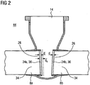
- Fig. 2 shows the shut-off valve 6 Fig. 1 with dismounted housing internals 32.
- the housing opening 14 is now open, that is, the interior of the housing 10 is accessible from the outside space 44.
- the sealing seats 24a, b are visible through the housing opening 14 and can be measured optically or with sliding calipers, not shown, or other measuring devices.
- the current state of the sealing seats 24a, b can be determined. In particular, it can be determined, for example, which thickness d the sealing seats 24a, b still have.
- the armor has 36 reduced from an original dashed line indicated thickness d 0 at the time of manufacture of the fitting 6 to the thickness d.
- a Clamping device 40 mounted in the connecting pipe 8a.
- the clamping device 40 is approximately disc-shaped and has a stop 42, with which it is placed on the sealing seat 24a.
- hydraulic cylinders 48 attached to the clamping device 40 are pressed against the inner wall 50 of the connecting pipe 8a.
- the hydraulic cylinder 48 is thus part of a fastening element, with which the clamping device 40 is fixed in the connecting pipe 8a.
- the clamping device 40 is securely fixed in the connecting pipe 8a.
- the clamping device 40 In order to center the radial position of the clamping device 40 in the connecting tube 8a exactly on its central longitudinal axis 52, the clamping device 40 also radially outwardly facing sensor 54, by which the distance of the clamping device 40 to the inner wall 50 at the respective position of the sensor 54 are measured can.
- the hydraulic cylinders 48 are driven accordingly to finally center the tensioning device 40.
- Fig. 3 shows the clamping device 40 in the final adjusted mounting state M.
- the tensioning device 40 has an abutment 56 which lies in the assembled state M in the interior of the housing 10 or points there and is accessible from the housing opening 14 forth.
- a reference point 57 namely the center of the thrust bearing 56 lies on the central longitudinal axis 52. This serves as a fixed geometric starting position for the bearing 64 to be attached as described below.
- a processing machine 58 is now likewise introduced through the housing opening 14 into the housing 10 in the direction of the arrow 38.
- the processing machine 58 is in Fig. 3 a lathe, which has a shaft arm 62 as the base support 60. On the base support 60 to the abutment 56 matching bearing 64 is firmly attached.
- Fig. 3 shows the processing machine 58 also in the assembled state M, namely, when the bearing 64 is inserted into the abutment 56 and stored in this.
- a drive 66 is attached, at the opposite end of the shaft arm 62, a machining head 68.
- the machining head 68 is rotatable about an axis of rotation 74 which to the longitudinal axis 76 of the shaft arm 62 a fixed , in the example has a 90 ° angle.
- a turning tool 78 is held as a machining tool or tool, which is deliverable relative to the shaft arm 62 only in the radial direction 80 and in the axial direction 82 with respect to the axis of rotation 74. This is achieved by a set screw 84 and a slide valve 86th
- the processing machine 58 is fixed or mounted on the housing 10 by the bearing 64 via the abutment 56 and the tensioning device 40 and is pivotable only in accordance with the degree of freedom permitted by the bearing 64 and abutment 56. On the other hand, it is stored at another point.
- a holder 70 is screwed, on which in turn adjustably a carriage 72 is mounted, which guides the shaft arm 62.
- the sealing seat 24b is to be machined such that its plane plane 88 assumes a predetermined angle ⁇ relative to the center plane 90 of the fitting 6, since the shut-off fitting 6 is a wedge slide.
- the processing machine 58 is to be set against the connection pipe 8b accordingly. Since the rotation axis 74 is fixed to the longitudinal axis 76, is the angle ⁇ is adjusted by moving the carriage 72 in the direction of the arrow 92, and so the shaft arm 62 is tilted in the abutment 56. The correct angle ⁇ is controlled by an inclinometer 94 mounted on the shaft arm 62.
- a processing step B1 is now carried out on the sealing seat 24b.
- the turning tool 78 in the radial direction 80 and axial direction 82 namely the remaining armor 36 of the thickness d is turned off from the connecting pipe 8b.
- the base material 34 is accessible again for a stable subsequent welding.
- a step e) the processing machine 58 is now released from the abutment 56 and removed through the housing opening 14 against the direction of the arrow 38 from the shut-off valve 6. Since the refurbishment of the sealing seat 24b has not yet been completed, the steps c) to e) are repeated in a step f) correspondingly often with changing processing machines 58.
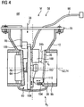
- FIG. 4 Now another processing machine 58 in the form of a TIG orbital welding machine is inserted through the housing opening 14 in the housing 10 in the direction of arrow 38.
- the processing machine 58 has again at its base support 60, a bearing 64 with which it is mounted in the abutment 56.
- the base support 60 is again fixed to the bracket 70 to fix the processing machine 58 in its mounting position M. This is done via a fixing arm 95.
- the base support 60 is connected to a supply module 98 arranged in the outer space 44. This contains eg the power source and the controller for the welder.
- a weldment 100 in the form of a wire roll, a wire feed 102 and a TIG welding torch 104 is arranged on the base support 60.
- the TIG welding torch 104 Via a rotary drive 106 and a radial slide 108 and an axial slide 110, the TIG welding torch 104 is always automatically held at the correct distance from the object to be welded, namely the end 26 of the connecting pipe 8b.
- processing step B2 a new armor 36 (indicated by dashed lines) welded onto the connecting pipe 8b.
- the processing step B2 ends when the armor 36 has reached the original thickness d 0 with a certain post-processing projection.
- the processing machine 58 is then removed from the housing 10 against the direction of the arrow 38.
- the clamping device 40 is now inserted into the already processed connecting pipe 8b and restored in the manner described above, the sealing seat 24a on its original dimension of the thickness d 0 .
- Fig. 5 shows as an alternative shut-off valve 6 a high-pressure slide, which also has a housing 10 and connecting pipes 8a, b, a sealing element 22, a spindle 18, a hand wheel 20 and a housing cover 16.
- a seat ring 114a, b is welded to the end 26 of the connecting pipes 8a, b respectively facing the interior of the housing 10. This carries in each case the sealing seat 24a, b.
- the restoration again includes the same steps as above.
- the sealing seats 24a, b are not restored on site, but removed together with their seat rings 114a, b from the valve 6 and restored outside or exchanged.
- the restored or new seat rings 114a, b are then re-welded.
- a clamping device 40 is completely spent in the interior of the connecting pipe 8a, which is equipped with hydraulic cylinders 48 and sensors 58 in order to be centered and fixed to the central longitudinal axis 52.
- a processing machine 58 is also introduced again in the direction of the arrow 38 in the interior of the housing 10 or in the present case also in the interior of the connecting pipe 8a.
- the tensioning device is held in the same connection tube whose sealing seat is also to be restored.
- Fig. 6 shows detail VI Fig. 5 ,
- the seat ring 114a which is connected via a weld 116 to the housing 10 or the connection pipe 8a, can be seen.
- the clamping device 40 is supported by the hydraulic cylinders 48 on the inner wall 50 of the connecting pipe 8a.
- the processing machine 58 is held with its bearing 64.
- the processing machine 58 is again a lathe with a turning tool 78 as a tool, which now separates the weld 116.
- the seat ring 114a may then be released and removed through the housing opening 14.
- the processing machine 58 is then replaced by a welding unit or machine, not shown, in the form of an alternative processing machine 58, which has a new seat ring 114a or a restored seat ring 114a in the in Fig. 6 welded in again shown original state.
- the holder 40 remains permanently clamped during all processing steps and thus forms with their abutment 56 a reference position for docking machine tools 58 to match the corresponding processing steps geometrically exactly to each other.
- a degassing slot 118 (in FIG Fig. 6 dashed indicated) present, in order to divert emerging welding gas during processing.
- Fig. 6 also shows how in a high-pressure sealing seat it is applied in the form of a multi-layer armor 36 on the seat ring 114a and not directly on the base material 34 of the housing 10 or connecting tube 8a.
Landscapes
- Engineering & Computer Science (AREA)
- Mechanical Engineering (AREA)
- Turning (AREA)
- Electrical Discharge Machining, Electrochemical Machining, And Combined Machining (AREA)
- Grinding And Polishing Of Tertiary Curved Surfaces And Surfaces With Complex Shapes (AREA)
- Pipe Accessories (AREA)
- Arc Welding In General (AREA)
- Automatic Assembly (AREA)
- Lift Valve (AREA)
Description
- Die Erfindung betrifft ein Verfahren und eine Vorrichtung zur Bearbeitung eines Dichtsitzes einer Absperrarmatur.
- Zum Absperren von Rohrleitungen in Kraftwerks- oder Industrieanlagen werden verschiedenste Absperrarmaturen eingesetzt. Als Industrieanlagen kommen z.B. sämtliche mit Fluiden arbeitende Anlagen, z.B. der Chemieindustrie, in Frage. Für Kraftwerke sind hier sämtliche Kraftwerkstypen wie z.B. Kernkraftwerke, d.h. Siede- und Druckwasserreaktoren angesprochen.
- In Rede stehende Absperrarmaturen sind z.B. Absperrschieber und Rückschlagklappen im Nieder(ND)-, Mittel(MD)- und Hochdruckbereich(HD), entsprechend ca. bis 40bar, 40-160bar und über 160bar. Die Nennweiten entsprechender Absperrarmaturen liegen im Bereich von ca. 50 bis 1200mm.
- Die Absperrarmaturen haben hierbei mindestens zwei Anschlussrohre, die ins Innere eines Armaturengehäuses führen. Dort weisen solche Anschlussrohre mit Dichtfunktionalität an ihren stirnseitigen Enden Dichtsitze auf. Diese verlaufen z.B. zur Mittenebene der Absperrarmatur parallel (ND-Rückschlagklappe) oder in einer hierzu zum Armaturenoberteil hin öffnend geneigten Ebene (HD-Keilschieber).
- Zum Schließen der Armaturen werden z.B. über eine Axialbewegung einer Spindel oder eine Schwenkbewegung einer Rückschlagklappe Dichtelemente, wie z.B. Dichtplatten in den Bereich der Anschlussrohre des Armaturengehäuses gefahren, welche sich an den Dichtsitz anlegen. Bei Absperrschiebern presst z.B. die druckbeaufschlagte Seite (Zulauf-Anschlussrohr) eines Absperrschiebers die Dichtplatte gegen den Dichtring bzw. Dichtsitz auf der drucklosen Seite (Ablauf-Anschlussrohr). So entsteht eine abdichtende Wirkung. Bei Absperrarmaturen wird hierdurch z.B. das Medium unabhängig von der Flussrichtung blockiert, bei Rückschlagklappen wird der Medienfluss nur gegen eine vorgegebene Flussrichtung blockiert.
- Absperrschieber werden in der Regel wegabhängig über Fernantriebe bzw. Handräder eingestellt. Die Wegabhängigkeit des Verfahrweges bedeutet, dass die Dichtplatten gerade soweit in das Armaturengehäuse ein- und ausgefahren werden, dass diese auch unter Berücksichtigung sämtlicher Temperaturausdehnungen den Dichtsitz sicher blockieren bzw. freigeben und nicht mit dem Armaturengehäuse kollidieren.
- Da die Dichtflächen in entsprechenden Absperrarmaturen einer hohen Belastung standhalten müssen, sind diese z.B. bei Niederdruckarmaturen bis Nenndruck (PN, Pressure Nominal) PN40 gegen Verschleiß mit einer 17% Chromstahlpanzerung gesichert bzw. ausgeführt. Mit anderen Worten wird auf das stirnseitige Ende des Anschlussrohres eine einige Millimeter starke Schicht Chromstahl als Hartauftragung aufgeschweißt.
- Nach einer bestimmten Anzahl von Öffnungs- und Schließzyklen einer Absperrarmatur unter Betriebsbedingungen stellt sich aufgrund der teilweise hohen Flächenpressung ein Verschleißverhalten an den Dichtelementen, insbesondere auch den Dichtsitzen ein. Das Dichtverhalten der Absperrarmatur nimmt mit zunehmender Abnutzung der Dichtflächen ab und die Dichtheit der Armaturen ist nicht mehr gewährleistet. Eine entsprechende Abnutzung kann je nach Belastungsfall bereits nach einem oder nach etlichen tausend Schließzyklen einsetzen. Dies ist stark abhängig von der Art des durch die Armatur fließenden Mediums, den auftretenden Temperaturen usw..
- Es ist daher notwendig, bei entsprechendem Verschleiß die Absperrarmatur bzw. deren Dichtungen zu sanieren. Für die Schiebereinbauten, z.B. die Dichtplatten, Schieber, Rückschlagklappen etc. ist dies problemlos möglich, da diese aus dem Armaturengehäuse ausgebaut werden können und außerhalb der Armatur saniert werden können. Der Transport der ausgebauten Teile ist in der Regel unproblematisch. Die Sanierung kann daher z.B. vor Ort in der Anlage außerhalb der Armatur, in einer Standortwerkstatt der Anlage oder bei einem Hersteller der Armatur geschehen.
- Problematisch ist die Sanierung der Dichtsitze der Anschlussrohre. Der Zugang zu den Dichtsitzen innerhalb des Armaturengehäuses ist beengt. Bekannt ist ein Verfahren zum Nachschleifen der beschädigten Dichtflächen vor Ort unter Zuhilfenahme von sogenannten Schieberschleifmaschinen z.B. aus der
DD 217 171 A1 DD 278 542 A1 DE 24 00 077 A1 und derDD 109 822 A1 - Da das Nachschleifen nur im µm-Bereich stattfindet und hierbei keinerlei Berücksichtigung der absoluten Armaturenmaße Beachtung findet, kann z.B. eine einseitige Abnutzung eines schrägsitzenden Dichtsitzes nicht korrigiert werden, weshalb der Dichtsitzwinkel im Armaturengehäuse trotz nachgeschliffener planparalleler Oberfläche nicht mehr korrekt ist.
- Sind die im Gehäuse der Absperrarmatur fest angebrachten Dichtsitze soweit beschädigt, dass das o.g. Nachschleifen keine Abhilfe mehr schafft, erfolgt die Beseitigung der Beschädigung durch Heraustrennen der gesamten Absperrarmatur aus dem Rohrleitungssystem. Die ausgetrennte Armatur wird dann zur Sanierung in eine Standortwerkstatt oder zum Armaturenhersteller verschafft, welche über erforderliche Sanierungsmaschinen verfügen. Die Armatur wird dann in Ihrer Gesamtheit an den Außenflächen in einer Spannvorrichtung eingespannt und durch übliche Bearbeitungsmaschinen, wie Drehmaschinen, Schweißmaschinen etc. saniert.
- Alternativ wird die defekte Armatur nicht saniert, sondern entsorgt und an der ursprünglichen Stelle des Leitungssystems in der Kraftwerks- oder Industrieanlage eine neue bzw. Austauscharmatur eingebracht. Das Austrennen und Wiedereinschweißen einer Armatur ist mit erheblichem Kostenaufwand verbunden. Außerdem sind insbesondere für Kernkraftwerke umfangreiche Reparaturspezifikationen notwendig. Das Heraustrennen von großen und schweren Armaturen aus dem bestehenden Rohrsystem erfordert Spezialausrüstung, spezielle Hebevorrichtungen und ist aufgrund des beengten Umgebungsraumes der Armatur oft nur mit erheblichem Aufwand möglich, da z.B. zunächst umliegende Installations- oder Gebäudeteile entfernt werden müssen, um die Armatur überhaupt austrennen zu können.
- Der Transport der Armatur innerhalb einer Kraftwerks-oder Industrieanlage oder zum Armaturenhersteller ist aufwändig und kostenintensiv. Besonders im Kernkraftwerksbereich sind die Armaturen kontaminiert, was zu zusätzlichem Aufwand und Kosten führt. Die Handhabung beim Heraustrennen der Armaturen ist mit erhöhtem Verletzungsrisiko der beteiligten Personen und der Gefahr verbunden, die Absperrarmatur selbst oder sonstige Komponenten der Industrieanlage zu beschädigen. Beim erneuten Einschweißen der Armaturen sind Ausgleichsrohre anzufertigen, da die Wärmeeinflusszonen vollständig beseitigt und Schnittverluste ausgeglichen werden müssen. Die Einbauposition der Armatur ist im Ursprungszustand wiederherzustellen. Wird eine neue Absperrarmatur eingesetzt, ist mit einem deutlich erhöhten Planungsaufwand zu rechnen, da für die neue Armatur aktuelle Regelwerke, wie z.B. die Druckgeräterichtlinie, zu berücksichtigen sind. Im Vergleich zu den für die in der Regel viele Jahre alte Armatur geltenden früheren Richtlinien sind dann erhöhte Sicherheiten gefordert. So ist z.B. bei neuen Absperrarmaturen die Wandstärke und damit das Gewicht gegenüber einer alten bisherig verwendeten Armatur erhöht. Infolge dessen ist es unter Umständen notwendig, eine strukturdynamische Berechnung des betroffenen Rohrleitungssystems bzw. Leitungsabschnittes durchzuführen, welche das Mehrgewicht der neuen Armatur berücksichtigt. Im ungünstigsten Fall müssen Halterungen hinzugefügt oder verstärkt werden. Ein langwieriges und kostenaufwändiges Baugenehmigungsverfahren ist unter Umständen notwendig. Außerdem müssen aufgrund der durchgeführten Schweißungen im Rohrsystem z.B. gesamte Rohrabschnitte, welche die Armatur enthalten, einer erneuten Druckprüfung unterzogen werden.
- Aus der
DE 10 2005 004 232 A1 ist es auch bekannt, vor Ort an einer Dichtfläche ein Auftragsschweißen durchzuführen. So kann die Oberfläche der Dichtfläche zunächst auf ein Niveau über der ursprünglichen konstruktiven Vorgabe gebracht werden, das dann schließlich auf das Reparaturniveau abgetragen wird. - Des Weiteren ist aus der
DE 87 06117 U1 ein Verfahren zum Nachschleifen der Dichtflächen bekannt, wobei die dafür eingesetzte Schieberschleifmaschine ein an der Spannvorrichtung axial verschiebbares Gegenlager aufweist. - Aufgabe der Erfindung ist es daher, ein verbessertes Verfahren und eine verbesserte Vorrichtung zur Bearbeitung eines Dichtsitzes einer in einer Kraftwerks- oder Industrieanlage montieren Absperrarmatur anzugeben.
- Die Erfindung beruht auf der prinzipiellen Idee, die gehäusefesten Dichtsitze der Absperrarmatur vor Ort im eingebauten Zustand im Leitungssystem zu ertüchtigen. Die Absperrarmatur bzw. deren Armaturengehäuse verbleibt damit montiert in einer Kraftwerks- oder Industrieanlage. Mit dem entsprechenden Sanierungsverfahren vor Ort lassen sich die meisten der oben genannten nachteiligen Punkte betreffende Ein- und Ausbau und Transport umgehen.
- Gemäß der Erfindung wird eine komplexe Vorrichtung für das betreffende Verfahren benutzt, welche in der Anlage zur Reparatur der eingebauten Armatur eingesetzt wird. Die entsprechenden Dichtsitze sind nur von der Gehäuseöffnung her zugänglich, wenn nämlich Armaturenoberteil, Antriebe, Dichtplatten und sonstige Einbauten entfernt sind. Da die Dichtsitze in der Regel etwa parallel, die Gehäuseöffnung aber senkrecht zur Mittelebene der Armatur liegen, muss in der Regel eine Kraft- und Bewegungsumlenkung um ca. 90° stattfinden. Bei Keilplattenschiebern muss die Bearbeitungsvorrichtung zusätzlich um den Neigungswinkel der Dichtsitze bezüglich der Spindellängsachse, also der genannten Mittelebene verstellbar sein. Der Platzmangel im Armaturengehäuse erfordert eine spezielle Bauweise der Bearbeitungsvorrichtung, ohne deren Funktionalität einzuschränken. Die Bearbeitungsvorrichtung ist jeweils in flacher Bauweise zu konstruieren, um z.B. zwischen zwei Anschlussrohren bzw. Dichtsitzen eines Keilschiebers eingesetzt werden zu können. Erfindungsgemäß kann so die Bearbeitung der Dichtsitze aus einer Richtung senkrecht zu deren Querebene erfolgen. Die entsprechenden Kräfte für die Bearbeitung sind dann besonders einfach aufzubringen.
- Hinsichtlich des Verfahrens wird die Aufgabe gelöst durch ein Verfahren gemäß Patentanspruch 1 zur Bearbeitung eines am Ende eines Anschlussrohres angeordneten Dichtsitzes einer in einer Kraftwerks- oder Industrieanlage montierten Absperrarmatur, mit folgenden Schritten:
In einem Schritt a) wird das Armaturenoberteil und die Einbauten vom Gehäuse der Absperrarmatur entfernt, wodurch eine Gehäuseöffnung freigegeben wird. Diese Gehäuseöffnung ist z.B. für Armaturen im Nieder- und Mitteldruckbereich ein Flansch, für Armaturen im Hochdruckbereich ein Gehäusehals bzw. -dom. In einem Schritt b) wird eine Spannvorrichtung durch die Gehäuseöffnung in das angesprochene Anschlussrohr oder ein weiteres, z.B. das dem zu bearbeitenden Dichtsitz gegenüberliegende Anschlussrohr, eingebracht. Die Spannvorrichtung wird an der Innenwand des Anschlussrohres befestigt. Die Spannvorrichtung weist ein Gegenlager auf, welches im Montagezustand, also bei befestigter Spannvorrichtung, an der dem Gehäuseinneren zugewandten Seite der Spannvorrichtung liegt und somit weiterhin von der Gehäuseöffnung aus zugänglich ist.
Dabei bilden Spannvorrichtung bzw. Gegenlager einen geometrisch exakt ortsfixierten Referenzort in der Absperrarmatur. - In einem Schritt c) wird durch die Gehäuseöffnung eine Bearbeitungsmaschine in das Gehäuse eingebracht. Die Bearbeitungsmaschine trägt ein Lager, mit welchem es am Gegenlager gelagert wird. In einem Schritt d) wird mit der Bearbeitungsmaschine ein Bearbeitungsschritt am Dichtsitz durchgeführt. Danach wird in einem Schritt e) die Bearbeitungsmaschine vom Gegenlager gelöst und durch die Gehäuseöffnung entfernt. In einem Schritt f) werden bei Bedarf die Schritte c) bis e) mit einer anderen oder der gleichen Bearbeitungsmaschine wiederholt.
- Nach Beendigung der eigentlichen Arbeit am Dichtsitz wird in einem Schritt g) die Spannvorrichtung vom Anschlussrohr gelöst und durch die Gehäuseöffnung wieder aus der Absperrarmatur entfernt. In einem Schritt h) werden abschließend das Armaturenoberteil und die Einbauten wieder am Gehäuse angebracht und die Armatur dadurch wieder betriebsbereit komplettiert.
- Erfindungsgemäß wird es also durch die Spannvorrichtung bzw. deren Gegenlager und das an der Bearbeitungsmaschine angebrachte Lager möglich, die Bearbeitungsmaschine in eine definierte Position innerhalb des Armaturengehäuses zu verbringen und von dort aus gezielt hochgenaue Arbeiten am Dichtsitz durchzuführen. Die Spannvorrichtung bzw. das Gegenlager bilden somit einen geometrisch exakt fixierten und ruhenden Referenzort in der Armatur, welcher für sämtliche Bearbeitungsschritte bzw. deren Genauigkeit ortsfixiert bleibt. Das Gegenlager bildet damit einen Referenzpunkt bzw. ein Referenzmaß innerhalb der Armatur. Dieses ist dann relativ zum Nullmaß einer Armatur, z.B. einem Flansch eines Niederdruckschiebers fixiert und kann während der Restaurierung wiederum selbst als Nullmaß benutzt werden. Insbesondere können nacheinander durchgeführte Arbeitsschritte z.B. mit verschiedenen Bearbeitungsmaschinen in exakt geometrisch aufeinander aufbauenden Positionen durchgeführt werden, da sämtliche Bearbeitungsmaschinen stets am einmal fixierten und während des Verfahrens nicht bewegten Gegenlager in definierter geometrischer Position gelagert werden. Die Spannvorrichtung wird also z.B. an eine beliebige, aber feste Position verbracht und dann die Position des Gegenlagers im Koordinatensystem der Armatur ermittelt. Die Bearbeitung erfolgt dann mit den Bearbeitungsmaschinen ausgehend maßhaltig von der einmal festgelegten Position aus.
- Bekannt ist es bisher, einen Bearbeitungskopf bzw. ein Werkzeug einer Maschine auszutauschen. Der Hauptkörper der Maschine, z.B. deren Antrieb und Gehäuse bleiben bestehen. Gewechselt werden z.B. verschiedene Dreh-, Bohr, oder Fräsköpfe. Gemäß der Erfindung wird jedoch die gesamte Bearbeitungsmaschine gewechselt. Dies bringt den Vorteil, jede Maschine für sich, auch z.B. hinsichtlich des Antriebsmotors, des Gehäuses usw., individuell und optimal für jeden einzelnen der Bearbeitungsschritte gestalten zu können. Die geometrische Referenzlage, die durch das Gegenlager bestimmt ist, gilt dann jedoch für alle, wie unterschiedlich auch immer gestalteten Bearbeitungsmaschinen.
- Da das Gegenlager im Bereich des zu bearbeitenden Dichtsitzes fixiert wird, sind die Entfernungen zum Arbeitsbereich gering. Die verwendeten Bearbeitungsmaschinen können stabil und einfach ausgeführt werden, was hohe Bearbeitungskräfte ermöglicht.
- Die Dichtplatten bzw. Schiebereinbauten können in üblicher Weise wie bisher außerhalb des Armaturengehäuses, z.B. in einer Standortwerkstatt, in Stand gesetzt werden.
- Das Verfahren wird z.B. vorab an entsprechenden Dummys der Armaturen qualifiziert, damit die Reproduzierbarkeit an der in der Anlage zu bearbeitenden Armatur sichergestellt ist. Es erfolgt mit anderen Worten eine Simulation an einem Muster, um z.B. auch Prüf- oder Zulassungsverfahren zu absolvieren.
- In einer bevorzugten Ausführungsform des Verfahrens wird als Bearbeitungsschritt die zum Gehäuseinneren weisende Stirnseite des Anschlussrohres abgedreht oder abgeschliffen. Durch einen derartigen Arbeitsschritt ist es möglich, z.B. eine Passung für einen neu einzufügenden Schiebersitzring in einer exakt definierten geometrische Ebene abzudrehen oder abzuschleifen, eine Panzerung eines Dichtsitzes bis auf das Grundmaterial in einer definierten Ebene abzutragen oder eine neu aufgebrachte Panzerung sowohl planparallel als auch in einer definierten Eben bezüglich der Armaturengeometrie präzise zu schleifen. Durch Drehen lässt sich eine mechanische Endbearbeitung der Dichtflächen, durch formgebendes Schleifen deren Feinbearbeitung realisieren. Durch die Abtragung auf das Grundmaterial ist eine spätere gute Vernetzung neu aufzubringenden Materials mit dem Grundmaterial der Armatur bzw. des Anschlussrohres sichergestellt.
- In einer weiteren bevorzugten Ausführungsform des Verfahrens wird als Bearbeitungsschritt eine den Dichtsitz bildende Panzerung auf die Stirnseite des Anschlussrohres aufgeschweißt. Insbesondere in Kombination dieses Bearbeitungsschrittes mit dem oben genannten Schritt ist folgende Vorgehensweise möglich: Bei einer zu sanierenden Armatur wird nach Demontage der Schiebereinbauten der zunächst noch vorhandene bzw. der aktuelle Zustand des Dichtsitzes optisch bzw. mechanisch vermessen. Z.B. wird die Dicke der restlichen noch auf dem Anschlussrohr vorhandenen Panzerung vermessen. Anschließend wird die Spannvorrichtung wie beschrieben angebracht und auf eine Sollposition bezüglich der Armaturengeometrie fixiert, so dass z.B. das Gegenlager einen Fixpunkt an einer definierten Ortslage in der Armatur bildet. Anschließend wird mit einer Bearbeitungsmaschine der Dichtsitz des gegenüberliegenden Anschlussrohres bis auf das Grundmaterial abgedreht, dann mit einer Schweißmaschine bzw. -vorrichtung als Bearbeitungsmaschine eine neue Panzerung in dem ursprünglichen Herstellungsmaß des Dichtsitzes aufgebracht. Anschließend wird nochmals mit der Drehvorrichtung der Dichtsitz auf das ursprüngliche Herstellermaß abgedreht und schließlich mit einer Schleifmaschine planparallel fein geschliffen. So wird also die exakte ursprüngliche Dichtflächengeometrie im Originalzustand, auch bezüglich der exakten geometrischen Lage in der Armatur, wieder hergestellt.
- Mit dem erfindungsgemäßen Verfahren kann also ein neu eingebrachter und damit hochqualitativer Härteverlauf in Form einer neuen Panzerung bzw. eines neuen Dichtsitzes in die bestehende Absperrarmatur eingebracht werden. Hierbei sind z.B. Härten von 340-400HV (Härte nach Vickers) möglich. Mit diesem Verfahren werden die Standzeiten und das Verschleißverhalten aufgrund der neu eingebrachten Härten an den Dichtflächen deutlich verbessert. Weder am Schieber selbst noch an dem Rohrsystem, in welchem der Schieber fest eingebaut verbleibt, werden damit Änderungen durchgeführt. Die Spezifikation der Armatur wird nicht geändert, da der ursprüngliche Zustand zum Zeitpunkt der Herstellung der Armatur nahezu identisch wieder hergestellt wird. Die Erstellung von Vorprüfunterlagen ist wesentlich vereinfacht. Z.B. müssen in einem Kernkraftwerk dann nur Reparaturvorprüfunterlagen erstellt werden. Der gesamte Aufwand des Aus- und Einschweißens der Armatur entfällt, die Anlage wird nicht verändert, muss nicht neu abgedrückt werden, benötigt keinerlei neue Betriebsprüfung, statische oder dynamische Berechnungen. Die Entsorgungsproblematik ist deutlich minimiert, da z.B. kein altes, verstrahltes Armaturengehäuse entsorgt werden muss.
- Die Bearbeitungsmaschine sollte hierbei Freiheitsgrade von fünf Achsen aufweisen, nämlich eine Verschiebung in Längsrichtung des Anschlussrohres, eine Verkippung zum Dichtsitz hin, um verschiedenen Winkeln von Keilschiebern zu folgen, eine Rotation um die Längsachse, und die Verschiebung senkrecht zur Längsachse (Bewegung in einer Ebene: 2 Freiheitsgrade). Damit können beliebige Dichtsitze bearbeitet werden.
- In einer alternativen Verfahrensvariante wird als Bearbeitungsschritt ein den Dichtsitz tragender Gehäusesitzring vom Anschlussrohr getrennt oder an dieses angeschweißt. Durch einen derartigen Bearbeitungsschritt lassen sich auch Hochdruckarmaturen restaurieren, bei welchen der Dichtsitz selbst nicht vor Ort saniert werden kann. Der Dichtsitz wird nämlich als mehrschichtige Lage von besonderer Härte auf einen entsprechenden Sitzring aufgebracht. Hierzu ist eine Spezialwerkstatt notwendig, die z.B. eine waagerechte Lagerung des Sitzringes erlaubt. Durch den Bearbeitungsschritt wird jedoch der Sitzring aus der Armatur gelöst. Dieser alleine kann mit erheblich weniger Aufwand in eine Spezialwerkstatt verbracht werden und dort saniert werden. Nach Restaurierung wird er wieder in die ursprüngliche Armatur eingebracht. Alternativ wird sofort ein neuer Sitzring in die Armatur integriert. Die restliche Armatur verbleibt in der Anlage und muss nicht mit ausgetauscht werden. Auch hier sind in der Regel Genehmigungsverfahren oder sonstiger Zusatzaufwand deutlich verringert.
- Bei einem derartigen Bearbeitungsschritt wird in der Regel die Spannvorrichtung in das gleiche Anschlussrohr eingebracht, welches auch bearbeitet werden soll. Die Spannvorrichtung wird daher beispielsweise weiter in das Anschlussrohr eingebracht als wenn bei einer Niederdruckarmatur der dem Anschlussrohr gegenüberliegende Dichtsitz restauriert werden soll. Dennoch befindet sich die Spannvorrichtung wieder so nahe wie möglich am Bearbeitungsort.
- In einer weiteren Verfahrensvariante wird die Spannvorrichtung so im Anschlussrohr befestigt, dass ein Referenzpunkt der Spannvorrichtung auf der Mittellängsachse des Anschlussrohres liegt. Hierdurch wird die oben angesprochene geometrisch exakte bzw. vordefinierte Lage der Spannvorrichtung oder des Gegenlagers im Koordinatensystem der Armatur erzielt. Im Montagezustand der Bearbeitungsmaschine, wenn dieses im Gegenlager gehalten ist, ist die Bearbeitungsmaschine dann stets an einer bekannten Position in der Armaturengeometrie positioniert.
- Hinsichtlich der Vorrichtung wird die Aufgabe der Erfindung gelöst durch eine Vorrichtung gemäß Patentanspruch 7 zur Bearbeitung eines am Ende eines Anschlussrohres angeordneten Dichtsitzes einer in einer Kraftwerks- oder Industrieanlage montierten Absperrarmatur.
- Die Vorrichtung umfasst eine Spannvorrichtung, welche durch eine Gehäuseöffnung der Absperrarmatur in das zu restaurierende oder ein weiteres Anschlussrohr einbringbar ist. Die Spannvorrichtung weist ein Gegenlager auf und enthält ein mit der Innenwand des Anschlussrohres zusammenwirkendes Befestigungselement, um die Spannvorrichtung sicher und für die Dauer des oben genannten Verfahrens stabil im Anschlussrohr zu befestigen. Dabei bilden Spannvorrichtung bzw. Gegenlager einen geometrisch exakt ortsfixierten Referenzort in der Absperrarmatur. Die Vorrichtung umfasst außerdem mindestens eine durch die Gehäuseöffnung in das Gehäuse einbringbare Bearbeitungsmaschine zur Durchführung eines Bearbeitungsschrittes am Dichtsitz. Die Bearbeitungsmaschine weist ein Lager auf, welches im Gegenlager lagerbar ist. Die erfindungsgemäße Vorrichtung wurde bereits im Zusammenhang mit dem erfindungsgemäßen Verfahren zusammen mit ihren Vorteilen beschrieben.
- In einer speziellen Ausgestaltung der Erfindung weist das Befestigungselement einen gegen die Innenwand des Anschlussrohres anfahrbaren Hydraulikzylinder auf. Durch einen oder insbesondere mehrere solcher Hydraulikzylinder kann die Spannvorrichtung besonders einfach und mit hoher Festigkeit im Anschlussrohr befestigt werden. Die Spannvorrichtung ist hierbei in der Regel scheiben- oder zylinderförmig und wird im Montagezustand mit ihrer Querebene parallel zu einer Querebene des Anschlussrohres fixiert. Durch eine nach außerhalb der Absperrarmatur führende Hydraulikleitung können die Hydraulikzylinder ferngesteuert werden. Durch wahlweise Ansteuerung verschiedener Hydraulikzylinder kann die Lage der Spannvorrichtung in einer Querebene zum Anschlussrohr einfach verändert werden, wenn die Hydraulikzylinder sich im Montagzustand in etwa radialer Richtung des Anschlussrohres erstrecken.
- In einer weiteren bevorzugten Ausgestaltung umfasst die Spannvorrichtung mindestens zwei an der Innenseite des Anschlussrohres anlegbare Messfühler. Durch die Messfühler kann die tatsächliche Lage der Spannvorrichtung im Anschlussrohr ermittelt werden und diese insbesondere zusammen mit steuerbaren Hydraulikzylindern zu einem selbstjustierenden System kombiniert werden, so dass sich beispielsweise die Spannvorrichtung im Anschlussrohr automatisch zu dessen Mittellängsachse zentriert. Mit anderen Worten ergeben sich durch eine entsprechende Regelung so selbstjustierende Messfühler.
- In einer weiteren Ausführungsform der Erfindung ist das Gegenlager eine fixierbare Schnellspannaufnahme. Das Lager ist dann alternativ oder zusätzlich ein Walzen- oder Kugelkopf. Durch die Schnellspannaufnahme kann eine Bearbeitungsmaschine mit ihrem Lager besonders schnell und einfach an der Spannvorrichtung befestigt werden. Ein Wechsel zu einer anderen Bearbeitungsmaschine ist dann schnell und einfach möglich. Durch die Fixierbarkeit kann die relative Lage zwischen Lager und Gegenlager und damit zwischen Bearbeitungsmaschine und Spannvorrichtung fixiert werden. So ist dann auch die Bearbeitungsmaschine starr im Bezugssystem der Armatur fixiert, um z.B. während eines Bearbeitungsschrittes eine definierte Ausgangslage für die Bearbeitungsmaschine bzw. ein von dieser gehaltenes Werkzeug, wie einen Drehmeißel, zu behalten. Durch einen Walzenkopf erhält die Bearbeitungsmaschine nur einen einzigen Freiheitsgrad der Beweglichkeit, nämlich um die Walzenachse eine Rotationsbewegung durchzuführen. Dies ist z.B. besonders wünschenswert, wenn eine Bearbeitungsmaschine auf den Keilwinkel eines Keilschieberdichtsitzes eingestellt werden soll und hier verschiedene Winkel einzunehmen sind. Ein Kugelkopf hingegen erlaubt entsprechende Verkippungen der Bearbeitungsmaschine um zwei Achsen, wobei jedoch die Fixierung in einer Ebene, z.B. in Axialrichtung des Anschlussrohres, gegeben bleibt.
- In einer weiteren bevorzugten Ausführungsform ist das Gegenlager fest an der Spannvorrichtung angeordnet und außerdem derart an dieser platziert, dass es durch eine Justierung der Spannvorrichtung im Anschlussrohr auf der Mittellängsachse des Anschlussrohres zentrierbar ist. Mit anderen Worten kann also die Spannvorrichtung immer so im Anschlussrohr justiert werden, dass das Gegenlager auf der Mittellängsachse des Anschlussrohres zentriert ist. Das Gegenlager bildet so einen standardisierten Ausgangspunkt für das jeweilige Lager einer Bearbeitungsmaschine. Bei der Entwicklung der Bearbeitungsmaschinen kann so z.B. immer davon ausgegangen werden, dass sich auch deren Lager zum Bearbeitungszeitpunkt auf der Mittellängsachse des Anschlussrohres befindet. Die Bearbeitungsgeometrie kann so besonders einfach eingestellt werden.
- In einer weiteren bevorzugten Ausführungsform weist die Bearbeitungsmaschine einen im Montagezustand aus der Gehäuseöffnung ragenden, starren Grundträger auf, der das Lager umfasst. Ein Bearbeitungskopf ist wiederum fest am Grundträger angebracht, so dass dessen Neigungswinkel zum Grundträger nicht variiert. Aus einer derartigen Vorrichtung folgt, dass eine Veränderung des Neigungswinkels des Bearbeitungskopfes zum Dichtsitz alleine durch eine Verkippung des Grundträgers im Gegenlager bewirkt ist. Diese wiederum kann von außerhalb des Armaturengehäuses einfach, z.B. händisch anhand einer Lehre oder eine Kulisse eingestellt werden. Mit andern Worten bildet der Grundträger eine Art Hebel, welcher außerhalb der Gehäuseöffnung zugänglich und bedienbar ist und mit welchem die Neigung des Bearbeitungskopfes zum Dichtsitz variiert werden kann. Auch dies eignet sich, um in besonders einfacher Weise die Sollneigung der Bearbeitungsmaschine und damit des Dichtsitzes bezüglich der Absperrarmatur einzustellen.
- In einer Variante dieser Ausführungsform ist die Bearbeitungsmaschine eine Dreh- oder Schleifmaschine mit einem im Montagezustand außerhalb des Gehäuses liegenden Antrieb. Der Grundträger bildet einen Wellenarm, welcher den Antrieb mit dem Bearbeitungskopf verbindet. Der Bearbeitungskopf trägt ein um eine Rotationsachse rotierbares Dreh- oder Schleifelement, wobei die Rotationsachse eine feste Relativlage zum Wellenarm aufweist. So ergibt sich also eine Schleif-bzw. Drehmaschine, deren Arbeitsebene sich im Montagezustand durch Bewegung des Wellenarmes von außerhalb des Armaturengehäuses einstellen lässt.
- Der Schleifschritt im o.g. Verfahren kann z.B. auch mit einer herkömmlichen Schieberschleifmaschine erfolgen. Durch die Dreh- und Schleifmaschine der erfindungsgemäßen Vorrichtung ist allerdings eine separate Schleifmaschine in einer Anlage generell nicht mehr erforderlich, was wiederum die Gesamtkosten für Wartungsmaschinen senkt. Alle Arbeiten können mit der erfindungsgemäßen Vorrichtung durchgeführt werden.
- In einer weiteren Ausgestaltung dieser Erfindungsvariante ist das Dreh- oder Schleifelement, z.B. ein Drehmeißel, als Werkzeug nur in Radial- und Längsrichtung bezüglich der Rotationsachse zustellbar. Die axiale sowie radiale Angriffsposition des Werkzeugs in Längsrichtung der Mittellängsachse des Anschlussrohres wird also durch die Zustellung bewirkt. Die Lage der Ebene der Angriffsposition hingegen wird durch Justierung des Wellenarmes erreicht.
- In einer weiteren bevorzugten Ausführungsform ist die Bearbeitungsmaschine eine Schweißmaschine bzw. -anlage, wobei im Montagezustand deren Versorgungseinheit, z.B. die Spannungsversorgung und die Steuerung, außerhalb des Gehäuses liegen. Innerhalb des Gehäuses liegt ein das Lager aufweisender Grundträger. Auf dem Grundträger sind ein Schweißgutbehälter und ein um eine Rotationsachse rotierbarer Schweißkopf angeordnet. Die Rotationsachse liegt z.B. senkrecht zur Sollebene der Dichtfläche oder der Mittellängsachse des Anschlussrohres.
- In einer besonders bevorzugten Ausführungsform ist die Schweißmaschine eine WIG-Orbital-Schweißanlage bzw. -maschine. Diese bietet der Vorteil, dass hier der Abstand zwischen Schweißkopf und Werkstück von der Anlage selbst geregelt wird. Die Schweißanlage muss daher nur bezüglich der Querebene des Dichtsitzes exakt zentriert werden.
- In einer weiteren bevorzugten Ausführungsform umfasst die Bearbeitungsmaschine eine an der Gehäuseöffnung befestigbare Halterung. Z.B. wird eine Trägerplatte am Flansch einer Niederdruckarmatur oder am Dom einer Hochdruckarmatur befestigt, wobei wiederum in der Trägerplatte ein Teil der Bearbeitungsmaschine, z.B. der Grundträger bzw. Wellenarm, fixierbar ist. So wird im Montagezustand die gesamte Bearbeitungsmaschine zumindest gegen unbeabsichtigtes Lösen, meist jedoch auch in definierter Ortsposition in der Absperrarmatur fixiert. Insbesondere bei überkopfmontierten Absperrarmaturen ist so die Bearbeitungsmaschine sicher in seiner Montage- bzw. Arbeitsposition gehalten.
- In einer bevorzugten Ausgestaltung dieser Variante erlaubt die Halterung im Montagezustand der Bearbeitungsmaschine eine Veränderung und Fixierung der Lage der Bearbeitungsmaschine im Lager. Dies ist z.B. in Verbindung mit der oben genannten Variation des Anstellwinkels eines Dichtsitzes eines Keilschiebers sinnvoll, wenn z.B. die Fixierung in einer üblichen 3° oder 7° Schräglage der Bearbeitungsmaschine bzw. deren Werkzeugs möglich ist.
- Für eine weitere Beschreibung der Erfindung wird auf die Ausführungsbeispiele der Zeichnungen verwiesen. Es zeigen, jeweils in einer schematischen Prinzipskizze:
- Fig. 1
- einen Niederdruck-Keilschieber als Absperrarmatur,
- Fig. 2
- die Armatur aus
Fig. 1 im zerlegten Zustand, - Fig. 3
- eine Armatur entsprechend
Fig. 2 mit eingesetzter Spannvorrichtung und Dreh- und Schleifmaschine, - Fig. 4
- die Armatur aus
Fig. 3 mit einer Schweißmaschine - Fig. 5
- eine Hochdruckarmatur mit eingesetzter Spannvorrichtung und Drehmaschine,
- Fig. 6
- das Detail VI aus
Fig. 5 . -
Fig. 1 zeigt einen Ausschnitt aus einer Rohrleitung 4 einer Anlage 2, im Beispiel einer Kraftwerksanlage, stellvertretend für eine beliebige Kraftwerks- oder Industrieanlage. In die Rohrleitung 4 ist eine Absperrarmatur 6 integriert, im Beispiel ein Niederdruck-Absperrschieber. Die Absperrarmatur 6 weist als festen Bestandteil zwei Anschlussrohre 8a,b auf, über welche sie mit der Rohrleitung 4 fest verschweißt ist. Die Anschlussrohre 8a,b sind Teil eines Gehäuses 10 der Armatur 6, welches an einem Flansch 12 eine Gehäuseöffnung 14 aufweist.Fig. 1 zeigt die Absperrarmatur 6 im endmontierten Zustand, wenn nämlich auf dem Flansch 12 ein Gehäusedeckel 16 montiert ist, der eine Spindel 18 trägt. Die Spindel 18 endet an ihrem einen Ende in einem Handrad 20. Am anderen Ende der Spindel 18 befindet sich ein Dichtelement 22 in Form zweier Dichtplatten. Das Dichtelement 22 wirkt mit zwei Dichtsitzen 24a,b zusammen, welche im Inneren des Gehäuses 10 an den stirnseitigen Enden der Anschlussrohre 8a,b angeordnet sind. Die Dichtsitze 24a,b sind derart gebildet, dass auf dem Grundmaterial 34 der Anschlussrohre 8a,b eine Panzerung 36, im Beispiel aus 17% Chromstahl an den jeweiligen Enden 26 stirnseitig aufgeschweißt ist. Gehäusedeckel 16, Spindel 18, Handrad 20 und Dichtelement 22 bilden zusammen die sogenannten Gehäuseeinbauten 32 der Absperrarmatur 6, welche sämtlich vom Gehäuse 10 entfernbar sind. - In
Fig. 1 ist die Absperrarmatur 6 im geschlossenen Zustand gezeigt, d.h. das Dichtelement 22 liegt an den Dichtsitzen 24a,b an. Zum Öffnen der Armatur 6 wird das Handrad 20 in Richtung des Pfeils 28 gedreht, woraufhin die Spindel 18 das Dichtelement 22 in Richtung des Pfeils 30 von den Dichtsitzen 24a,b abhebt. Die Enden 26 der Anschlussrohre 8a,b sind dann vollständig geöffnet und nicht dargestelltes Medium kann in beiden Richtungen ungehindert durch die Rohrleitung 4 strömen. - Durch den Betrieb der Absperrarmatur 6 nutzen sich die Dichtsitze 24a,b stark ab. Die Absperrarmatur 6 muss diesbezüglich saniert werden. Gemäß der Erfindung verbleibt die Absperrarmatur 6 hierzu in der Rohrleitung 4.
- In einem ersten Verfahrensschritt a) werden zunächst sämtliche Gehäuseeinbauten 32 entfernt.
Fig. 2 zeigt die Absperrarmatur 6 ausFig. 1 mit demontierten Gehäuseeinbauten 32. Die Gehäuseöffnung 14 ist nun offen, das heißt das Innere des Gehäuses 10 ist vom Außenraum 44 aus zugänglich. Außerdem sind so die Dichtsitze 24a,b durch die Gehäuseöffnung 14 einsehbar und können optisch bzw. mit nicht dargestellten Schiebelehren oder anderen Messvorrichtungen vermessen werden. So kann der aktuelle Zustand der Dichtsitze 24a,b ermittelt werden. Insbesondere kann z.B. festgestellt werden, welche Dicke d die Dichtsitze 24a,b noch aufweisen. Durch den Betrieb der Absperrarmatur 6 hat sich die Panzerung 36 von einer ursprünglichen gestrichelt angedeuteten Dicke d0 im Herstellungszeitpunkt der Armatur 6 auf die Dicke d reduziert. - Zur Sanierung der Dichtsitze 24a,b wird nun weiterhin folgendermaßen vorgegangen. Durch die Gehäuseöffnung 14 wird gemäß
Fig. 3 in einem Schritt b) in Richtung des Pfeils 38 eine Spannvorrichtung 40 im Anschlussrohr 8a angebracht. Die Spannvorrichtung 40 ist etwa scheibenförmig ausgebildet und weist einen Anschlag 42 auf, mit dem sie auf dem Dichtsitz 24a aufgelegt wird. Über eine in den Außenraum 44 führende Hydraulikleitung 46 werden an der Spannvorrichtung 40 angebrachte Hydraulikzylinder 48 gegen die Innenwand 50 des Anschlussrohres 8a gepresst. Der Hydraulikzylinder 48 ist damit Teil eines Befestigungselements, mit dem die Spannvorrichtung 40 im Anschlussrohr 8a befestigt wird. Diese sind im Wesentlichen radial beweglich. Hierdurch wird die Spannvorrichtung 40 sicher im Anschlussrohr 8a fixiert. Um die radiale Lage der Spannvorrichtung 40 im Anschlussrohr 8a genau auf dessen Mittellängsachse 52 zu zentrieren, weist die Spannvorrichtung 40 außerdem radial nach außen weisende Messfühler 54 auf, durch welche der Abstand der Spannvorrichtung 40 zur Innenwand 50 an der jeweiligen Position der Messfühler 54 gemessen werden kann. Die Hydraulikzylinder 48 werden entsprechend angesteuert, um schließlich die Spannvorrichtung 40 zu zentrieren.Fig. 3 zeigt die Spannvorrichtung 40 im endjustierten Montagezustand M. - Die Spannvorrichtung 40 weist ein Gegenlager 56 auf, welches im Montagezustand M im Inneren des Gehäuses 10 liegt bzw. dort hin weist und von der Gehäuseöffnung 14 her zugänglich ist. Außerdem liegt ein Referenzpunkt 57, nämlich der Mittelpunkt des Gegenlagers 56 auf der Mittellängsachse 52. Dieser dient als fixe geometrische Ausgangslage für die, wie nachstehend beschrieben anzufügenden Lager 64.
- In einem Schritt c) wird nun in Richtung des Pfeils 38 eine Bearbeitungsmaschine 58 ebenfalls durch die Gehäuseöffnung 14 in das Gehäuse 10 eingeführt. Die Bearbeitungsmaschine 58 ist in
Fig. 3 eine Drehmaschine, welche als Grundträger 60 einen Wellenarm 62 aufweist. Am Grundträger 60 ist ein zum Gegenlager 56 passendes Lager 64 fest angebracht.Fig. 3 zeigt die Bearbeitungsmaschine 58 ebenfalls im Montagezustand M, wenn nämlich das Lager 64 in das Gegenlager 56 eingeführt bzw. in diesem gelagert ist. An dem, im Montagezustand M aus dem Gehäuse 10 ragenden Ende des Wellenarmes 62 ist ein Antrieb 66 angebracht, am gegenüberliegenden Ende des Wellenarms 62 ein Bearbeitungskopf 68. Der Bearbeitungskopf 68 ist um eine Rotationsachse 74 rotierbar, welche zur Längsachse 76 des Wellenarm 62 einen festen, im Beispiel einen 90°-Winkel aufweist. Am Bearbeitungskopf 68 ist als Bearbeitungswerkzeug bzw. Werkzeug ein Drehmeißel 78 gehalten, welcher relativ zum Wellenarm 62 lediglich in Radialrichtung 80 und in Axialrichtung 82 bezüglich der Rotationsachse 74 zustellbar ist. Dies wird erreicht durch eine Stellschraube 84 und einen Planschieber 86. - Die Bearbeitungsmaschine 58 ist einerseits durch das Lager 64 über das Gegenlager 56 und die Spannvorrichtung 40 am Gehäuse 10 fixiert bzw. gelagert und ist dabei lediglich gemäß dem durch das Lager 64 und Gegenlager 56 ermöglichten Freiheitsgrad verschwenkbar. Andererseits ist es an einem weiteren Punkt gelagert. Am Flansch 12 ist nämlich eine Halterung 70 verschraubt, auf welcher wiederum verstellbar ein Schlitten 72 montiert ist, welcher den Wellenarm 62 führt.
- Der Dichtsitz 24b ist so zu bearbeiten, dass dessen Planebene 88 zur Mittenebene 90 der Armatur 6 einen vorgegebenen Winkel α einnimmt, da es sich bei der Absperrarmatur 6 um einen Keilschieber handelt. Mit anderen Worten ist die Bearbeitungsmaschine 58 entsprechend gegen das Anschlussrohr 8b anzustellen. Da die Rotationsachse 74 zur Längsachse 76 fixiert ist, wird der Winkel α dadurch eingestellt, dass der Schlitten 72 in Richtung des Pfeils 92 verfahren wird, und so der Wellenarm 62 im Gegenlager 56 verkippt wird. Der korrekte Winkel α wird durch einen Neigungsmesser 94 kontrolliert, welcher am Wellenarm 62 montiert ist.
- In einem Verfahrensschritt d) wird nun ein Bearbeitungsschritt B1 am Dichtsitz 24b durchgeführt. Durch Zustellung des Drehmeißels 78 in Radialrichtung 80 und Axialrichtung 82 wird nämlich die noch vorhandene Panzerung 36 der Dicke d vom Anschlussrohr 8b abgedreht. So ist das Grundmaterial 34 für eine stabile folgende Aufschweißung wieder zugänglich.
- In einem Schritt e) wird nun die Bearbeitungsmaschine 58 vom Gegenlager 56 gelöst und durch die Gehäuseöffnung 14 entgegen der Richtung des Pfeils 38 aus der Absperrarmatur 6 entnommen. Da die Sanierung des Dichtsitzes 24b noch nicht abgeschlossen ist, werden nun in einem Schritt f) die Schritte c) bis e) entsprechend oft mit wechselnden Bearbeitungsmaschinen 58 wiederholt.
- Gemäß
Fig. 4 wird nun in Richtung des Pfeils 38 eine andere Bearbeitungsmaschine 58 in Form einer WIG-Orbitalschweißmaschine durch die Gehäuseöffnung 14 in das Gehäuse 10 eingeführt. Die Bearbeitungsmaschine 58 weist wieder an seinem Grundträger 60 ein Lager 64 auf, mit welchem es im Gegenlager 56 befestigt wird. Auch hier wird der Grundträger 60 wieder an der Halterung 70 fixiert, um die Bearbeitungsmaschine 58 in ihrer Montageposition M zu fixieren. Dies geschieht über einen Fixierarm 95. Über eine Versorgungsleitung 96 ist der Grundträger 60 mit einem im Außenraum 44 angeordneten Versorgungsmodul 98 verbunden. Dieses enthält z.B. die Stromquelle und die Steuerung für das Schweißgerät. Am Grundträger 60 ist ein Schweißgutbehälter 100 in Form einer Drahtrolle, ein Drahtvorschub 102 und ein WIG-Schweißbrenner 104 angeordnet. Über einen Drehantrieb 106 sowie einen Radialschlitten 108 und einen Axialschlitten 110 wird der WIG-Schweißbrenner 104 immer automatisch im richtigen Abstand vom zu schweißenden Objekt, nämlich dem Ende 26 des Anschlussrohres 8b gehalten. - Während des in
Fig. 4 gezeigten Bearbeitungsschrittes B2 wird eine neue Panzerung 36 (gestrichelt angedeutet) auf das Anschlussrohr 8b aufgeschweißt. Der Bearbeitungsschritt B2 endet, wenn die Panzerung 36 die ursprüngliche Dicke d0 mit einem bestimmten, für eine Nachbearbeitung dienenden Überstand erreicht hat. Die Bearbeitungsmaschine 58 wird dann entgegen der Richtung des Pfeils 38 wieder aus dem Gehäuse 10 entfernt. - Es folgt ein weiterer Verfahrensschritt f). Gemäß
Fig. 3 wird nun nochmals die Drehmaschine als Bearbeitungsmaschine 58 eingesetzt. Die neu aufgebrachte Panzerung 36 wird mit dieser in einem Bearbeitungsschritt B3 auf das Ursprungsmaß der Dicke d0 abgedreht. Der Drehmeisel 78 wird dann in der Bearbeitungsmaschine 58 durch ein Polierwerkzeug 112 als Werkzeug ersetzt. Mit diesem wird in einem abschließenden Bearbeitungsschritt B4 der Dichtsitz 24b als Oberfläche der Panzerung 36 endbearbeitet bzw. glattpoliert. - Schließlich wird zunächst die Bearbeitungsmaschine 58 entfernt. Da nun die Bearbeitung des Dichtsitzes 24b abgeschlossen ist, wird anschließend in einem Verfahrensschritt g) auch die Spannvorrichtung 40 aus dem Gehäuse 10 gelöst und entfernt.
- Gegebenenfalls wird nun die Spannvorrichtung 40 in das bereits bearbeitete Anschlussrohr 8b eingelegt und in der Weise wie oben beschrieben der Dichtsitz 24a auf seinem Ursprungsmaß der Dicke d0 wiederhergestellt.
-
Fig. 5 zeigt als alternative Absperrarmatur 6 einen Hochdruckschieber, welcher ebenfalls ein Gehäuse 10 sowie Anschlussrohre 8a,b, ein Dichtelement 22, eine Spindel 18, ein Handrad 20 sowie eine Gehäusedeckel 16 aufweist. Im Gegensatz zu einem Niederdruckschieber ist jedoch am jeweils dem Inneren des Gehäuses 10 zugewandten Ende 26 der Anschlussrohre 8a,b ein Sitzring 114a,b angeschweißt. Dieser trägt jeweils den Dichtsitz 24a,b. - Die Restaurierung umfasst wieder sinngemäß die gleichen Schritte wie oben. Im Unterschied zu oben werden allerdings die Dichtsitze 24a,b nicht selbst vor Ort restauriert, sondern zusammen mit ihren Sitzringen 114a,b aus der Armatur 6 entfernt und außerhalb restauriert oder getauscht. Die restaurierten oder neue Sitzringe 114a,b werden dann wieder eingeschweißt.
- Zum Restaurieren der Absperrarmatur 6 werden wieder die gesamten Gehäuseeinbauten 32 (Dichtelemente 22, Spindel 18, Gehäusedeckel 16 usw.) entfernt, so dass eine Gehäuseöffnung 14 verbleibt, durch welche das Innere des Gehäuses 10 zugänglich ist. Entsprechend dem Vorgehen gemäß
Fig. 3 wird wiederum eine Spannvorrichtung 40 vollständig in das Innere des Anschlussrohres 8a verbracht, welche entsprechend mit Hydraulikzylindern 48 und Messfühlern 58 ausgerüstet ist, um zur Mittellängsachse 52 zentriert und fixiert zu werden. Im Gegenlager 56 kann dann wieder eine Bearbeitungsmaschine 58 eingesetzt werden. Die Bearbeitungsmaschine 58 wird ebenfalls wieder in Richtung des Pfeils 38 in das Innere des Gehäuses 10 bzw. im vorliegenden Fall auch in das Innere des Anschlussrohres 8a eingebracht. Im Unterschied zu oben ist die Spannvorrichtung jedoch im gleichen Anschlussrohr gehalten, dessen Dichtsitz auch restauriert werden soll. -
Fig. 6 zeigt das Detail VI ausFig. 5 . Zu sehen ist der Sitzring 114a, der über eine Schweißnaht 116 mit dem Gehäuse 10 bzw. dem Anschlussrohr 8a verbunden ist. Die Spannvorrichtung 40 stützt sich mit dem Hydraulikzylindern 48 an der Innenwand 50 des Anschlussrohres 8a ab. Im Gegenlager 56 ist die Bearbeitungsmaschine 58 mit ihrem Lager 64 gehalten. Die Bearbeitungsmaschine 58 ist wieder eine Drehmaschine mit einem Drehmeißel 78 als Werkzeug, welcher nun die Schweißnaht 116 auftrennt. Der Sitzring 114a kann dann gelöst und durch die Gehäuseöffnung 14 entfernt werden. Die Bearbeitungsmaschine 58 wird anschließend durch eine nicht dargestellte Schweißeinheit bzw. -maschine in Form einer alternativen Bearbeitungsmaschine 58 ersetzt, welches einen neuen Sitzring 114a bzw. einen restaurierten Sitzring 114a in den inFig. 6 gezeigten Urzustand wieder einschweißt. Auch hier verbleibt die Halterung 40 während sämtlicher Bearbeitungsschritte dauerhaft verspannt und bildet somit mit ihrem Gegenlager 56 eine Referenzlage für anzukoppelnde Bearbeitungsmaschinen 58, um die entsprechende Bearbeitungsschritte geometrisch exakt aufeinander abzustimmen. - In einer alternativen Ausführungsform ist am neu einzubringenden Sitzring 114a ein Entgasungsschlitz 118 (in
Fig. 6 gestrichelt angedeutet) vorhanden, um entstehendes Schweißgas bei der Bearbeitung abzuleiten. -
Fig. 6 zeigt außerdem, wie bei einem Hochdruckdichtsitz dieser in Form einer mehrschichtigen Panzerung 36 auf den Sitzring 114a und nicht direkt auf das Grundmaterial 34 des Gehäuses 10 bzw. Anschlussrohres 8a aufgebracht ist.
Claims (18)
- Verfahren zur Bearbeitung eines am Ende (26) eines Anschlussrohres (8a,b) angeordneten Dichtsitzes (24a,b) einer in einer Kraftwerks- oder Industrieanlage 2 montierten Absperrarmatur (6), mit folgenden Schritten:a) das Armaturenoberteil (16) und die Gehäuseeinbauten (32) werden vom Gehäuse (10) der Absperrarmatur (6) entfernt, wodurch eine Gehäuseöffnung (14) freigegeben wird,b) eine ein Gegenlager (56) aufweisende Spannvorrichtung (40) wird durch die Gehäuseöffnung (14) in das oder ein weiteres Anschlussrohr (8a,b) derart eingebracht und an dessen Innenwand (50) befestigt, dass Spannvorrichtung (40) bzw. Gegenlager (56) einen geometrisch exakt ortsfixierten Referenzort in der Absperrarmatur (6) bilden,c) durch die Gehäuseöffnung (14) wird eine, ein Lager (64) aufweisende Bearbeitungsmaschine (58) in das Gehäuse (10) eingebracht und mit ihrem Lager (64) am Gegenlager (56) gelagert,d) mit der Bearbeitungsmaschine (58) wird ein Bearbeitungsschritt (B1-4) am Dichtsitz (24a,b) durchgeführt,e) die Bearbeitungsmaschine (58) wird vom Gegenlager (56) gelöst und durch die Gehäuseöffnung (14) entfernt,f) bei Bedarf werden die Schritte c) bis e) mit einer anderen oder der gleichen Bearbeitungsmaschine (58) wiederholt,g) die Spannvorrichtung (40) wird vom Anschlussrohr (8a,b) gelöst und durch die Gehäuseöffnung (14) entfernt,h) das Armaturenoberteil (16) und die Einbauten (32) werden am Gehäuse (10) angebracht.
- Verfahren nach Anspruch 1, bei dem als Bearbeitungsschritt (B1-4) die zum Inneren des Gehäuses (10) weisende Stirnseite des Anschlussrohres (8a,b) abgedreht oder abgeschliffen wird.
- Verfahren nach einem der vorhergehenden Ansprüche, bei dem als Bearbeitungsschritt (B1-4) eine den Dichtsitz (24a,b) bildende Panzerung (36) auf die Stirnseite des Anschlussrohres (8a,b) aufgeschweißt wird.
- Verfahren nach einem der vorhergehenden Ansprüche, bei dem als Bearbeitungsschritt (B1-4) ein den Dichtsitz (24a,b) tragender Gehäusesitzring (114a,b) vom Anschlussrohr (8a,b) getrennt oder an dieses angeschweißt wird.
- Verfahren nach einem der vorhergehenden Ansprüche, bei dem die Spannvorrichtung (40) soweit in das Anschlussrohr (8a,b) eingeführt wird, bis sie mit einem Anschlag (42) an der zum Inneren des Gehäuses (10) weisenden Stirnseite des Anschlussrohres (8a,b) anliegt.
- Verfahren nach einem der vorhergehenden Ansprüche, bei dem die Spannvorrichtung (40) so im Anschlussrohr (8a,b) befestigt wird, dass ein Referenzpunkt (57) der Spannvorrichtung (40) auf der Mittellängsachse (52) des Anschlussrohres (8a,b) liegt.
- Vorrichtung zur Bearbeitung eines am Ende (26) eines Anschlussrohres (8a,b) angeordneten Dichtsitzes (24a,b) einer in einer Kraftwerks- oder Industrieanlage (2) montierten Absperrarmatur (6),- mit einer durch eine Gehäuseöffnung (14) der Absperrarmatur (6) in das oder ein weiteres Anschlussrohr (8a,b) einbringbaren Spannvorrichtung (40), die ein Gegenlager (56) und ein mit der Innenwand (50) des Anschlussrohres (8a,b) zusammenwirkendes Befestigungselement (47) enthält, wobei Spannvorrichtung (40) bzw. Gegenlager (56) einen geometrisch exakt ortsfixierten Referenzort in der Absperrarmatur (6) bilden,- mit mindestens einer durch die Gehäuseöffnung (14) in das Gehäuse einbringbaren Bearbeitungsmaschine (58) zur Durchführung eines Bearbeitungsschrittes (B1-4) am Dichtsitz (24a,b), wobei die Bearbeitungsmaschine (58) ein Lager (64) aufweist, das im Gegenlager (56) lagerbar ist.
- Vorrichtung nach Anspruch 7, bei der das Befestigungselement (47) einen gegen die Innenwand (50) des Anschlussrohres (8a,b) anfahrbaren Hydraulikzylinder (48) enthält.
- Vorrichtung nach einem der Ansprüche 7 bis 8, bei der die Spannvorrichtung (40) mindestens zwei an der Innenseite (50) des Anschlussrohres (8a,b) anlegbare Messfühler (54) aufweist.
- Vorrichtung nach einem der Ansprüche 7 bis 9, bei der das Gegenlager (56) eine fixierbare Schnellspannaufnahme und/oder das Lager (64) ein Walzen- oder Kugelkopf ist.
- Vorrichtung nach einem der Ansprüche 7 bis 10, bei der das Gegenlager (56) fest derart an der Spannvorrichtung (40) angeordnet ist, dass es durch eine Justierung der Spannvorrichtung (40) im Anschlussrohr (8a,b) auf dessen Mittellängsachse (52) zentrierbar ist.
- Vorrichtung nach einem der Ansprüche 7 bis 11, bei der die Bearbeitungsmaschine (58) einen im Montagezustand (M) aus der Gehäuseöffnung (14) ragenden starren, das Lager (64) tragenden Grundträger (60) und einen bezüglich seiner Neigung zum Dichtsitz (24a,b) an diesem fest angebrachten Bearbeitungskopf (68) aufweist, so dass eine Veränderung des Neigungswinkels (α) des Bearbeitungskopfes (68) zu einer Mittenebene (90) der Absperrarmatur (6) durch eine Verkippung des Grundträgers (60) im Gegenlager (56) bewirkt ist.
- Vorrichtung nach Anspruch 12, bei der die Bearbeitungsmaschine (58) eine Dreh- oder Schleifmaschine ist, mit einem im Montagezustand (M) außerhalb des Gehäuses (10) liegenden Antrieb (66), und einem vom Antrieb (66) zum einem Arbeitskopf (68) reichenden, den Grundträger (60) bildenden Wellenarm (62), wobei der Bearbeitungskopf (68) ein um eine Rotationsachse (74) rotierbares Dreh- (78) oder Schleifelement (112) umfasst und die Rotationsachse (74) eine feste Relativlage zum Wellenarm (62) aufweist.
- Vorrichtung nach Anspruch 13, bei der das Dreh- (78) oder Schleifelement (112) nur in Radial- (80) und Axialrichtung (82) bezüglich der Rotationsachse (74) zustellbar ist.
- Vorrichtung nach einem der Ansprüche 7 bis 14, bei der die Bearbeitungsmaschine (58) eine Schweißmaschine ist, mit einer im Montagezustand (M) außerhalb des Gehäuses (10) liegenden Versorgungseinheit (98), und einem innerhalb des Gehäuses (10) liegenden, das Lager (64) aufweisenden Grundträger (60), auf dem ein Schweißgutbehälter (100) und ein um eine Rotationsachse (74) rotierbarer Schweißkopf (104) angeordnet sind.
- Vorrichtung nach Anspruch 15, bei der die Schweißmaschine eine WIG-Orbitalschweißmaschine ist.
- Vorrichtung nach einem der Ansprüche 7 bis 16, bei der die Bearbeitungsmaschine (58) eine an der Gehäuseöffnung (14) befestigbare Halterung (70,95) umfasst.
- Vorrichtung nach Anspruch 17, bei der die Halterung (70,95) im Montagezustand (M) der Bearbeitungsmaschine (58) eine Veränderung und Fixierung der Lage der Bearbeitungsmaschine (58) im Gegenlager (56) erlaubt.
Applications Claiming Priority (2)
| Application Number | Priority Date | Filing Date | Title |
|---|---|---|---|
| DE200910046401 DE102009046401B4 (de) | 2009-11-04 | 2009-11-04 | Verfahren und Vorrichtung zur Bearbeitung eines Dichtsitzes einer Absperrarmatur |
| PCT/EP2010/066780 WO2011054891A1 (de) | 2009-11-04 | 2010-11-04 | Verfahren und vorrichtung zur bearbeitung eines dichtsitzes einer absperrarmatur |
Publications (3)
| Publication Number | Publication Date |
|---|---|
| EP2496383A1 EP2496383A1 (de) | 2012-09-12 |
| EP2496383B1 EP2496383B1 (de) | 2017-01-04 |
| EP2496383B9 true EP2496383B9 (de) | 2017-04-05 |
Family
ID=43734052
Family Applications (1)
| Application Number | Title | Priority Date | Filing Date |
|---|---|---|---|
| EP10779273.1A Active EP2496383B9 (de) | 2009-11-04 | 2010-11-04 | Verfahren und vorrichtung zur bearbeitung eines dichtsitzes einer absperrarmatur |
Country Status (10)
| Country | Link |
|---|---|
| US (1) | US8539673B2 (de) |
| EP (1) | EP2496383B9 (de) |
| JP (1) | JP5499178B2 (de) |
| CN (1) | CN102596502B (de) |
| BR (1) | BR112012010574B1 (de) |
| CA (1) | CA2778164C (de) |
| DE (1) | DE102009046401B4 (de) |
| PL (1) | PL2496383T3 (de) |
| RU (1) | RU2521569C2 (de) |
| WO (1) | WO2011054891A1 (de) |
Families Citing this family (17)
| Publication number | Priority date | Publication date | Assignee | Title |
|---|---|---|---|---|
| CN103737454A (zh) * | 2013-11-29 | 2014-04-23 | 成都欧浦特控制阀门有限公司 | 可定位的阀门研磨装置 |
| DE102014212149A1 (de) * | 2014-06-25 | 2015-12-31 | Siemens Aktiengesellschaft | Vorrichtung zur Verspreizung in einem Hohlraum und Verfahren zur Montage der Vorrichtung |
| RU2604238C2 (ru) * | 2015-02-05 | 2016-12-10 | Федеральное государственное бюджетное образовательное учреждение высшего профессионального образования "Липецкий государственный технический университет" (ЛГТУ) | Устройство для калибрования посадочных отверстий с полимерным покрытием в корпусных деталях |
| JP5881884B1 (ja) * | 2015-06-16 | 2016-03-09 | 三菱日立パワーシステムズ株式会社 | 弁座加工機および当該弁座加工機を用いた弁座加工方法 |
| JP5881883B1 (ja) * | 2015-06-16 | 2016-03-09 | 三菱日立パワーシステムズ株式会社 | 弁座加工機および当該弁座加工機を用いた弁座加工方法 |
| JP6335147B2 (ja) * | 2015-08-18 | 2018-05-30 | 日立Geニュークリア・エナジー株式会社 | ゲート弁シートリング摺り合わせ工具及びそれを用いたシートリングのメンテナンス方法 |
| CN106392881B (zh) * | 2016-10-25 | 2018-08-21 | 中国兵器科学研究院宁波分院 | 用于发动机一体式气门座圈巡边磨削加工的径向进给装置 |
| CN107030446B (zh) * | 2017-04-27 | 2023-01-31 | 上海电力股份有限公司吴泾热电厂 | 高温高压蒸汽阀门密封面在线修复系统 |
| RU2666973C1 (ru) * | 2017-10-13 | 2018-09-13 | Публичное акционерное общество "Транснефть" (ПАО "Транснефть") | Способ диагностики уплотнительных поверхностей запорной арматуры |
| CN107971729B (zh) * | 2017-12-25 | 2024-09-24 | 重庆众颖熙科技有限公司 | 一种用于压装缸盖导管与座圈的压装设备 |
| CN113714538B (zh) * | 2021-09-30 | 2022-07-01 | 浙江万得凯流体设备科技股份有限公司 | 一种截止阀的生产工艺 |
| CN115446335B (zh) * | 2022-08-18 | 2024-07-16 | 中核核电运行管理有限公司 | 一种用于主蒸汽安全阀在线加工的模块化机床 |
| CN116652500B (zh) * | 2023-06-20 | 2024-05-31 | 黄山市海纳智能制造有限公司 | 阀座加工用法兰盘与座体拼焊平台 |
| CN117140198B (zh) * | 2023-08-22 | 2025-10-31 | 吉林市佰丰科技有限公司 | 一种核电阀门智能化打磨检测系统 |
| CN118417994B (zh) * | 2023-11-22 | 2024-10-08 | 温州弘球机械有限公司 | 一种硬密封球阀阀体与密封座快速配磨装备及工艺 |
| CN117718683A (zh) * | 2023-12-08 | 2024-03-19 | 中船澄西船舶修造有限公司 | 一种喷油器与汽缸盖接触面修复方法 |
| CN120828285B (zh) * | 2025-09-17 | 2026-01-06 | 高特控股集团有限公司 | 一种截止阀的自动化组装系统及其工作方法 |
Family Cites Families (18)
| Publication number | Priority date | Publication date | Assignee | Title |
|---|---|---|---|---|
| DE2400077A1 (de) * | 1974-01-02 | 1975-07-17 | Alfred Butz | Vorrichtung zum schleifen von flaechen, insbesondere von dichtungsflaechen fuer absperrschieber oder dergleichen |
| US3881396A (en) * | 1974-03-01 | 1975-05-06 | Grimsley Ernest E | Portable boring bar |
| DD109822A1 (de) * | 1974-03-21 | 1974-11-20 | ||
| JPS5246521A (en) * | 1975-10-13 | 1977-04-13 | Okano Valve Seizo Kk | Self valve seat lapping device for sluice valve |
| US4000584A (en) * | 1976-04-01 | 1977-01-04 | The United States Of America As Represented By The Secretary Of The Navy | In-situ lapping apparatus for gate valves |
| FI59292C (fi) * | 1979-04-18 | 1981-07-10 | Waertsilae Oy Ab | Slidventil |
| DE3237902A1 (de) * | 1982-10-13 | 1984-04-19 | Bernd Dipl.-Ing. 5620 Velbert Kirchner | Flanschschleifmaschine |
| DD217171A1 (de) * | 1983-09-09 | 1985-01-09 | Orgreb Inst Kraftwerke | Einrichtung zur messung der anpresskraft des werkzeuges einer transportablen dichtflaechenschleifmaschine |
| DE8706117U1 (de) * | 1987-04-28 | 1987-06-11 | Unislip GmbH, 5180 Eschweiler | Andrückvorrichtung für Schieberschleifmaschinen |
| DD278542A1 (de) * | 1988-12-23 | 1990-05-09 | Magdeburger Armaturenwerke | Vorrichtung zum feinstschleifen von schiebergehaeusedichtflaechen |
| JPH03116107A (ja) * | 1989-09-29 | 1991-05-17 | Sumitomo Electric Ind Ltd | 光通信器 |
| US5732607A (en) * | 1995-05-12 | 1998-03-31 | Climax Portable Machine Tools, Inc. | Portable machine tool |
| US6007410A (en) * | 1998-08-07 | 1999-12-28 | Nerenberg; Bruno | Pipefacing tool |
| RU17297U1 (ru) * | 1999-10-05 | 2001-03-27 | Ооо "Экосервис" | Устройство для электродуговой наплавки |
| DE102005004232A1 (de) * | 2005-01-28 | 2006-08-10 | Ksc Kraftwerks-Service Cottbus Anlagenbau Gmbh, Sitz Peitz | Verfahren und Vorrichtung insbesondere zur Reparatur von Absperrarmaturen in Kraftwerken |
| RU46696U1 (ru) * | 2005-02-22 | 2005-07-27 | Общество с ограниченной ответственностью "Томскнефтехим" (ООО "Томскнефтехим") | Переносной станок для механической обработки уплотнительных поверхностей седел клиновых и шиберных задвижек без удаления их с трубопроводов |
| CN2827630Y (zh) * | 2005-07-06 | 2006-10-18 | 范金娥 | 一种阀门研磨机 |
| CN101176981A (zh) * | 2007-11-02 | 2008-05-14 | 赵殿纯 | 砂轮研磨机在阀门上的应用研磨方法 |
-
2009
- 2009-11-04 DE DE200910046401 patent/DE102009046401B4/de not_active Expired - Fee Related
-
2010
- 2010-11-04 PL PL10779273T patent/PL2496383T3/pl unknown
- 2010-11-04 EP EP10779273.1A patent/EP2496383B9/de active Active
- 2010-11-04 WO PCT/EP2010/066780 patent/WO2011054891A1/de not_active Ceased
- 2010-11-04 JP JP2012535879A patent/JP5499178B2/ja not_active Expired - Fee Related
- 2010-11-04 BR BR112012010574-4A patent/BR112012010574B1/pt not_active IP Right Cessation
- 2010-11-04 CA CA2778164A patent/CA2778164C/en not_active Expired - Fee Related
- 2010-11-04 RU RU2012122829/02A patent/RU2521569C2/ru active
- 2010-11-04 CN CN201080049996.5A patent/CN102596502B/zh not_active Expired - Fee Related
-
2012
- 2012-05-04 US US13/463,985 patent/US8539673B2/en not_active Expired - Fee Related
Also Published As
| Publication number | Publication date |
|---|---|
| US8539673B2 (en) | 2013-09-24 |
| EP2496383B1 (de) | 2017-01-04 |
| EP2496383A1 (de) | 2012-09-12 |
| US20120240403A1 (en) | 2012-09-27 |
| WO2011054891A1 (de) | 2011-05-12 |
| CA2778164C (en) | 2015-11-03 |
| RU2012122829A (ru) | 2013-12-10 |
| PL2496383T3 (pl) | 2017-09-29 |
| DE102009046401B4 (de) | 2012-08-09 |
| RU2521569C2 (ru) | 2014-06-27 |
| JP5499178B2 (ja) | 2014-05-21 |
| BR112012010574A2 (pt) | 2016-03-22 |
| DE102009046401A1 (de) | 2011-05-12 |
| JP2013510008A (ja) | 2013-03-21 |
| CN102596502A (zh) | 2012-07-18 |
| CA2778164A1 (en) | 2011-05-12 |
| CN102596502B (zh) | 2015-10-14 |
| BR112012010574B1 (pt) | 2021-01-05 |
Similar Documents
| Publication | Publication Date | Title |
|---|---|---|
| EP2496383B9 (de) | Verfahren und vorrichtung zur bearbeitung eines dichtsitzes einer absperrarmatur | |
| DE102006037490B4 (de) | Doppelseiten-Bearbeitungsmaschine | |
| DE102009051737B3 (de) | Verfahren zum Schleifen der Haupt- und Hublager einer Kurbelwelle durch Aussenrundschleifen und Schleifmaschine zum Durchführen des Verfahrens | |
| DE102007034706B3 (de) | Schleifzentrum und Verfahren zum gleichzeitigen Schleifen mehrerer Lager und endseitigen Flächen von Kurbelwellen | |
| DE102007061542A1 (de) | Verfahren und Vorrichtung zur Bearbeitung von Kaplanturbinenschaufeln | |
| EP2708324B1 (de) | Tischplatte für Federauflagetisch einer Federendenschleifmaschine sowie Federendenschleifmaschine damit | |
| EP1588224B1 (de) | Verfahren und vorrichtung zur herstellung von serviceschaufeln | |
| EP3116683A1 (de) | VERFAHREN UND VORRICHTUNG ZUM SCHLEIFEN VON GROßKURBELWELLEN | |
| WO2011124499A1 (de) | Rohrbearbeitungsmaschinen-spannfutter und überwachungsverfahren dafür | |
| WO2017211452A1 (de) | Maschine zur bearbeitung von werkstücken in optischer qualität | |
| EP2414134B1 (de) | Vorrichtung und verfahren zum wasserstrahlschneiden | |
| DE102013225292A1 (de) | Lünette zum abstützen von zentrischen werkstückbereichen während der bearbeitung von zentrischen und/oder exzentrischen werkstückbereichen insbesondere lagerstellen an kurbelwellen sowie schleifmaschine mit einer derartigen lünette | |
| WO2009146715A1 (de) | Büchsenaufweitvorrichtung und verfahren zum schmieden eines büchsenrohlings | |
| EP2087956A1 (de) | Verfahren und Bearbeitungsmaschine zur spanenden Bearbeitung komplexer Konturen von asymmetrischen Werkstücken | |
| DE102010010431B4 (de) | Verfahren zur Wiederaufarbeitung der verschlissenen Oberfläche von Mahlwalzen einer Gutbettwalzenmühle | |
| DE102014225295A1 (de) | Mess-lünette zum abstützen und vermessen von zentrischen werkstückbereichen, schleifmaschine mit einer derartigen mess-lünette sowie verfahren zum abstützen und vermessen von zentrischen werstückbereichen | |
| DE102015220525B4 (de) | Vorrichtung und Verfahren zur Bearbeitung eines Bauteils | |
| DE2336809B2 (de) | Maschine zum Lichtbogen-Schmelzschweissen von Rohr-Stumpfstößen in horizontaler Schweißnaht-Ebene | |
| DE202007000535U1 (de) | Gewichtsführungs- und Regelungssystem | |
| DE102005004232A1 (de) | Verfahren und Vorrichtung insbesondere zur Reparatur von Absperrarmaturen in Kraftwerken | |
| EP0309513B1 (de) | Spindelsystem für werkzeugmaschinen, insbesondere schleifmaschinen | |
| DE102010053405B4 (de) | Verfahren und Schleifmaschine zum Außenschleifen von stabförmigen Werkstücken | |
| DE102012108628B3 (de) | Vorrichtung zum Bearbeiten von Werkstücken mit integrierter Werkzeug-Abrichteinheit | |
| DE10237375A1 (de) | Vorrichtung und Verfahren zur geometrischen Vermessung eines im Querschnitt kreisförmigen Rohres | |
| DE602005004302T2 (de) | Verdichter und Verfahren zur Wiederherstellung eines Verdichters |
Legal Events
| Date | Code | Title | Description |
|---|---|---|---|
| PUAI | Public reference made under article 153(3) epc to a published international application that has entered the european phase |
Free format text: ORIGINAL CODE: 0009012 |
|
| 17P | Request for examination filed |
Effective date: 20120403 |
|
| AK | Designated contracting states |
Kind code of ref document: A1 Designated state(s): AL AT BE BG CH CY CZ DE DK EE ES FI FR GB GR HR HU IE IS IT LI LT LU LV MC MK MT NL NO PL PT RO RS SE SI SK SM TR |
|
| DAX | Request for extension of the european patent (deleted) | ||
| RAP1 | Party data changed (applicant data changed or rights of an application transferred) |
Owner name: AREVA GMBH |
|
| GRAP | Despatch of communication of intention to grant a patent |
Free format text: ORIGINAL CODE: EPIDOSNIGR1 |
|
| INTG | Intention to grant announced |
Effective date: 20151113 |
|
| GRAP | Despatch of communication of intention to grant a patent |
Free format text: ORIGINAL CODE: EPIDOSNIGR1 |
|
| INTG | Intention to grant announced |
Effective date: 20160624 |
|
| GRAS | Grant fee paid |
Free format text: ORIGINAL CODE: EPIDOSNIGR3 |
|
| GRAA | (expected) grant |
Free format text: ORIGINAL CODE: 0009210 |
|
| RAP1 | Party data changed (applicant data changed or rights of an application transferred) |
Owner name: WURZER, VOLKER |
|
| AK | Designated contracting states |
Kind code of ref document: B1 Designated state(s): AL AT BE BG CH CY CZ DE DK EE ES FI FR GB GR HR HU IE IS IT LI LT LU LV MC MK MT NL NO PL PT RO RS SE SI SK SM TR |
|
| REG | Reference to a national code |
Ref country code: GB Ref legal event code: FG4D Free format text: NOT ENGLISH |
|
| REG | Reference to a national code |
Ref country code: CH Ref legal event code: EP |
|
| REG | Reference to a national code |
Ref country code: AT Ref legal event code: REF Ref document number: 858775 Country of ref document: AT Kind code of ref document: T Effective date: 20170115 |
|
| REG | Reference to a national code |
Ref country code: IE Ref legal event code: FG4D Free format text: LANGUAGE OF EP DOCUMENT: GERMAN |
|
| GRAT | Correction requested after decision to grant or after decision to maintain patent in amended form |
Free format text: ORIGINAL CODE: EPIDOSNCDEC |
|
| REG | Reference to a national code |
Ref country code: DE Ref legal event code: R096 Ref document number: 502010013003 Country of ref document: DE |
|
| RAP2 | Party data changed (patent owner data changed or rights of a patent transferred) |
Owner name: WURZER, VOLKER |
|
| REG | Reference to a national code |
Ref country code: SE Ref legal event code: TRGR |
|
| REG | Reference to a national code |
Ref country code: LT Ref legal event code: MG4D Ref country code: NL Ref legal event code: MP Effective date: 20170104 |
|
| PG25 | Lapsed in a contracting state [announced via postgrant information from national office to epo] |
Ref country code: NL Free format text: LAPSE BECAUSE OF FAILURE TO SUBMIT A TRANSLATION OF THE DESCRIPTION OR TO PAY THE FEE WITHIN THE PRESCRIBED TIME-LIMIT Effective date: 20170104 |
|
| PG25 | Lapsed in a contracting state [announced via postgrant information from national office to epo] |
Ref country code: HR Free format text: LAPSE BECAUSE OF FAILURE TO SUBMIT A TRANSLATION OF THE DESCRIPTION OR TO PAY THE FEE WITHIN THE PRESCRIBED TIME-LIMIT Effective date: 20170104 Ref country code: LT Free format text: LAPSE BECAUSE OF FAILURE TO SUBMIT A TRANSLATION OF THE DESCRIPTION OR TO PAY THE FEE WITHIN THE PRESCRIBED TIME-LIMIT Effective date: 20170104 Ref country code: NO Free format text: LAPSE BECAUSE OF FAILURE TO SUBMIT A TRANSLATION OF THE DESCRIPTION OR TO PAY THE FEE WITHIN THE PRESCRIBED TIME-LIMIT Effective date: 20170404 Ref country code: IS Free format text: LAPSE BECAUSE OF FAILURE TO SUBMIT A TRANSLATION OF THE DESCRIPTION OR TO PAY THE FEE WITHIN THE PRESCRIBED TIME-LIMIT Effective date: 20170504 Ref country code: GR Free format text: LAPSE BECAUSE OF FAILURE TO SUBMIT A TRANSLATION OF THE DESCRIPTION OR TO PAY THE FEE WITHIN THE PRESCRIBED TIME-LIMIT Effective date: 20170405 |
|
| PG25 | Lapsed in a contracting state [announced via postgrant information from national office to epo] |
Ref country code: RS Free format text: LAPSE BECAUSE OF FAILURE TO SUBMIT A TRANSLATION OF THE DESCRIPTION OR TO PAY THE FEE WITHIN THE PRESCRIBED TIME-LIMIT Effective date: 20170104 Ref country code: LV Free format text: LAPSE BECAUSE OF FAILURE TO SUBMIT A TRANSLATION OF THE DESCRIPTION OR TO PAY THE FEE WITHIN THE PRESCRIBED TIME-LIMIT Effective date: 20170104 Ref country code: PT Free format text: LAPSE BECAUSE OF FAILURE TO SUBMIT A TRANSLATION OF THE DESCRIPTION OR TO PAY THE FEE WITHIN THE PRESCRIBED TIME-LIMIT Effective date: 20170504 Ref country code: ES Free format text: LAPSE BECAUSE OF FAILURE TO SUBMIT A TRANSLATION OF THE DESCRIPTION OR TO PAY THE FEE WITHIN THE PRESCRIBED TIME-LIMIT Effective date: 20170104 Ref country code: BG Free format text: LAPSE BECAUSE OF FAILURE TO SUBMIT A TRANSLATION OF THE DESCRIPTION OR TO PAY THE FEE WITHIN THE PRESCRIBED TIME-LIMIT Effective date: 20170404 |
|
| REG | Reference to a national code |
Ref country code: DE Ref legal event code: R097 Ref document number: 502010013003 Country of ref document: DE |
|
| PG25 | Lapsed in a contracting state [announced via postgrant information from national office to epo] |
Ref country code: EE Free format text: LAPSE BECAUSE OF FAILURE TO SUBMIT A TRANSLATION OF THE DESCRIPTION OR TO PAY THE FEE WITHIN THE PRESCRIBED TIME-LIMIT Effective date: 20170104 Ref country code: RO Free format text: LAPSE BECAUSE OF FAILURE TO SUBMIT A TRANSLATION OF THE DESCRIPTION OR TO PAY THE FEE WITHIN THE PRESCRIBED TIME-LIMIT Effective date: 20170104 Ref country code: SK Free format text: LAPSE BECAUSE OF FAILURE TO SUBMIT A TRANSLATION OF THE DESCRIPTION OR TO PAY THE FEE WITHIN THE PRESCRIBED TIME-LIMIT Effective date: 20170104 Ref country code: IT Free format text: LAPSE BECAUSE OF FAILURE TO SUBMIT A TRANSLATION OF THE DESCRIPTION OR TO PAY THE FEE WITHIN THE PRESCRIBED TIME-LIMIT Effective date: 20170104 |
|
| PLBE | No opposition filed within time limit |
Free format text: ORIGINAL CODE: 0009261 |
|
| STAA | Information on the status of an ep patent application or granted ep patent |
Free format text: STATUS: NO OPPOSITION FILED WITHIN TIME LIMIT |
|
| REG | Reference to a national code |
Ref country code: FR Ref legal event code: PLFP Year of fee payment: 8 |
|
| PG25 | Lapsed in a contracting state [announced via postgrant information from national office to epo] |
Ref country code: SM Free format text: LAPSE BECAUSE OF FAILURE TO SUBMIT A TRANSLATION OF THE DESCRIPTION OR TO PAY THE FEE WITHIN THE PRESCRIBED TIME-LIMIT Effective date: 20170104 Ref country code: DK Free format text: LAPSE BECAUSE OF FAILURE TO SUBMIT A TRANSLATION OF THE DESCRIPTION OR TO PAY THE FEE WITHIN THE PRESCRIBED TIME-LIMIT Effective date: 20170104 |
|
| 26N | No opposition filed |
Effective date: 20171005 |
|
| PG25 | Lapsed in a contracting state [announced via postgrant information from national office to epo] |
Ref country code: SI Free format text: LAPSE BECAUSE OF FAILURE TO SUBMIT A TRANSLATION OF THE DESCRIPTION OR TO PAY THE FEE WITHIN THE PRESCRIBED TIME-LIMIT Effective date: 20170104 |
|
| PG25 | Lapsed in a contracting state [announced via postgrant information from national office to epo] |
Ref country code: MC Free format text: LAPSE BECAUSE OF FAILURE TO SUBMIT A TRANSLATION OF THE DESCRIPTION OR TO PAY THE FEE WITHIN THE PRESCRIBED TIME-LIMIT Effective date: 20170104 |
|
| PG25 | Lapsed in a contracting state [announced via postgrant information from national office to epo] |
Ref country code: LU Free format text: LAPSE BECAUSE OF NON-PAYMENT OF DUE FEES Effective date: 20171104 |
|
| REG | Reference to a national code |
Ref country code: IE Ref legal event code: MM4A |
|
| PG25 | Lapsed in a contracting state [announced via postgrant information from national office to epo] |
Ref country code: MT Free format text: LAPSE BECAUSE OF FAILURE TO SUBMIT A TRANSLATION OF THE DESCRIPTION OR TO PAY THE FEE WITHIN THE PRESCRIBED TIME-LIMIT Effective date: 20170104 |
|
| PG25 | Lapsed in a contracting state [announced via postgrant information from national office to epo] |
Ref country code: IE Free format text: LAPSE BECAUSE OF NON-PAYMENT OF DUE FEES Effective date: 20171104 |
|
| REG | Reference to a national code |
Ref country code: AT Ref legal event code: MM01 Ref document number: 858775 Country of ref document: AT Kind code of ref document: T Effective date: 20171104 |
|
| PG25 | Lapsed in a contracting state [announced via postgrant information from national office to epo] |
Ref country code: AT Free format text: LAPSE BECAUSE OF NON-PAYMENT OF DUE FEES Effective date: 20171104 |
|
| PG25 | Lapsed in a contracting state [announced via postgrant information from national office to epo] |
Ref country code: HU Free format text: LAPSE BECAUSE OF FAILURE TO SUBMIT A TRANSLATION OF THE DESCRIPTION OR TO PAY THE FEE WITHIN THE PRESCRIBED TIME-LIMIT; INVALID AB INITIO Effective date: 20101104 |
|
| PG25 | Lapsed in a contracting state [announced via postgrant information from national office to epo] |
Ref country code: CY Free format text: LAPSE BECAUSE OF NON-PAYMENT OF DUE FEES Effective date: 20170104 |
|
| PG25 | Lapsed in a contracting state [announced via postgrant information from national office to epo] |
Ref country code: MK Free format text: LAPSE BECAUSE OF FAILURE TO SUBMIT A TRANSLATION OF THE DESCRIPTION OR TO PAY THE FEE WITHIN THE PRESCRIBED TIME-LIMIT Effective date: 20170104 |
|
| PG25 | Lapsed in a contracting state [announced via postgrant information from national office to epo] |
Ref country code: TR Free format text: LAPSE BECAUSE OF FAILURE TO SUBMIT A TRANSLATION OF THE DESCRIPTION OR TO PAY THE FEE WITHIN THE PRESCRIBED TIME-LIMIT Effective date: 20170104 |
|
| PG25 | Lapsed in a contracting state [announced via postgrant information from national office to epo] |
Ref country code: AL Free format text: LAPSE BECAUSE OF FAILURE TO SUBMIT A TRANSLATION OF THE DESCRIPTION OR TO PAY THE FEE WITHIN THE PRESCRIBED TIME-LIMIT Effective date: 20170104 |
|
| PGFP | Annual fee paid to national office [announced via postgrant information from national office to epo] |
Ref country code: CH Payment date: 20201118 Year of fee payment: 11 Ref country code: CZ Payment date: 20201103 Year of fee payment: 11 Ref country code: SE Payment date: 20201125 Year of fee payment: 11 Ref country code: FI Payment date: 20201119 Year of fee payment: 11 Ref country code: GB Payment date: 20201119 Year of fee payment: 11 Ref country code: FR Payment date: 20201120 Year of fee payment: 11 |
|
| PGFP | Annual fee paid to national office [announced via postgrant information from national office to epo] |
Ref country code: PL Payment date: 20201027 Year of fee payment: 11 Ref country code: BE Payment date: 20201125 Year of fee payment: 11 |
|
| REG | Reference to a national code |
Ref country code: CH Ref legal event code: PL |
|
| REG | Reference to a national code |
Ref country code: FI Ref legal event code: MAE |
|
| GBPC | Gb: european patent ceased through non-payment of renewal fee |
Effective date: 20211104 |
|
| PG25 | Lapsed in a contracting state [announced via postgrant information from national office to epo] |
Ref country code: SE Free format text: LAPSE BECAUSE OF NON-PAYMENT OF DUE FEES Effective date: 20211105 Ref country code: CZ Free format text: LAPSE BECAUSE OF NON-PAYMENT OF DUE FEES Effective date: 20211104 Ref country code: BE Free format text: LAPSE BECAUSE OF NON-PAYMENT OF DUE FEES Effective date: 20211130 |
|
| REG | Reference to a national code |
Ref country code: BE Ref legal event code: MM Effective date: 20211130 |
|
| PG25 | Lapsed in a contracting state [announced via postgrant information from national office to epo] |
Ref country code: LI Free format text: LAPSE BECAUSE OF NON-PAYMENT OF DUE FEES Effective date: 20211130 Ref country code: FI Free format text: LAPSE BECAUSE OF NON-PAYMENT OF DUE FEES Effective date: 20211104 Ref country code: CH Free format text: LAPSE BECAUSE OF NON-PAYMENT OF DUE FEES Effective date: 20211130 |
|
| PG25 | Lapsed in a contracting state [announced via postgrant information from national office to epo] |
Ref country code: GB Free format text: LAPSE BECAUSE OF NON-PAYMENT OF DUE FEES Effective date: 20211104 |
|
| PG25 | Lapsed in a contracting state [announced via postgrant information from national office to epo] |
Ref country code: FR Free format text: LAPSE BECAUSE OF NON-PAYMENT OF DUE FEES Effective date: 20211130 |
|
| PG25 | Lapsed in a contracting state [announced via postgrant information from national office to epo] |
Ref country code: PL Free format text: LAPSE BECAUSE OF NON-PAYMENT OF DUE FEES Effective date: 20211104 |
|
| P01 | Opt-out of the competence of the unified patent court (upc) registered |
Effective date: 20230414 |
|
| PGFP | Annual fee paid to national office [announced via postgrant information from national office to epo] |
Ref country code: DE Payment date: 20251119 Year of fee payment: 16 |