EP2497507B2 - Dispositif de dialyse - Google Patents
Dispositif de dialyse Download PDFInfo
- Publication number
- EP2497507B2 EP2497507B2 EP11157528.8A EP11157528A EP2497507B2 EP 2497507 B2 EP2497507 B2 EP 2497507B2 EP 11157528 A EP11157528 A EP 11157528A EP 2497507 B2 EP2497507 B2 EP 2497507B2
- Authority
- EP
- European Patent Office
- Prior art keywords
- dialysis
- heat pump
- heat
- fluid
- inlet means
- Prior art date
- Legal status (The legal status is an assumption and is not a legal conclusion. Google has not performed a legal analysis and makes no representation as to the accuracy of the status listed.)
- Active
Links
Images


Classifications
-
- A—HUMAN NECESSITIES
- A61—MEDICAL OR VETERINARY SCIENCE; HYGIENE
- A61M—DEVICES FOR INTRODUCING MEDIA INTO, OR ONTO, THE BODY; DEVICES FOR TRANSDUCING BODY MEDIA OR FOR TAKING MEDIA FROM THE BODY; DEVICES FOR PRODUCING OR ENDING SLEEP OR STUPOR
- A61M1/00—Suction or pumping devices for medical purposes; Devices for carrying-off, for treatment of, or for carrying-over, body-liquids; Drainage systems
- A61M1/14—Dialysis systems; Artificial kidneys; Blood oxygenators ; Reciprocating systems for treatment of body fluids, e.g. single needle systems for hemofiltration or pheresis
- A61M1/16—Dialysis systems; Artificial kidneys; Blood oxygenators ; Reciprocating systems for treatment of body fluids, e.g. single needle systems for hemofiltration or pheresis with membranes
- A61M1/1654—Dialysates therefor
- A61M1/1656—Apparatus for preparing dialysates
-
- A—HUMAN NECESSITIES
- A61—MEDICAL OR VETERINARY SCIENCE; HYGIENE
- A61M—DEVICES FOR INTRODUCING MEDIA INTO, OR ONTO, THE BODY; DEVICES FOR TRANSDUCING BODY MEDIA OR FOR TAKING MEDIA FROM THE BODY; DEVICES FOR PRODUCING OR ENDING SLEEP OR STUPOR
- A61M1/00—Suction or pumping devices for medical purposes; Devices for carrying-off, for treatment of, or for carrying-over, body-liquids; Drainage systems
- A61M1/14—Dialysis systems; Artificial kidneys; Blood oxygenators ; Reciprocating systems for treatment of body fluids, e.g. single needle systems for hemofiltration or pheresis
- A61M1/16—Dialysis systems; Artificial kidneys; Blood oxygenators ; Reciprocating systems for treatment of body fluids, e.g. single needle systems for hemofiltration or pheresis with membranes
- A61M1/1654—Dialysates therefor
- A61M1/1656—Apparatus for preparing dialysates
- A61M1/166—Heating
- A61M1/1662—Heating with heat exchange between fresh and used dialysate
-
- A—HUMAN NECESSITIES
- A61—MEDICAL OR VETERINARY SCIENCE; HYGIENE
- A61M—DEVICES FOR INTRODUCING MEDIA INTO, OR ONTO, THE BODY; DEVICES FOR TRANSDUCING BODY MEDIA OR FOR TAKING MEDIA FROM THE BODY; DEVICES FOR PRODUCING OR ENDING SLEEP OR STUPOR
- A61M1/00—Suction or pumping devices for medical purposes; Devices for carrying-off, for treatment of, or for carrying-over, body-liquids; Drainage systems
- A61M1/14—Dialysis systems; Artificial kidneys; Blood oxygenators ; Reciprocating systems for treatment of body fluids, e.g. single needle systems for hemofiltration or pheresis
- A61M1/16—Dialysis systems; Artificial kidneys; Blood oxygenators ; Reciprocating systems for treatment of body fluids, e.g. single needle systems for hemofiltration or pheresis with membranes
- A61M1/1654—Dialysates therefor
- A61M1/1656—Apparatus for preparing dialysates
- A61M1/166—Heating
- A61M1/1664—Heating with temperature control
-
- A—HUMAN NECESSITIES
- A61—MEDICAL OR VETERINARY SCIENCE; HYGIENE
- A61M—DEVICES FOR INTRODUCING MEDIA INTO, OR ONTO, THE BODY; DEVICES FOR TRANSDUCING BODY MEDIA OR FOR TAKING MEDIA FROM THE BODY; DEVICES FOR PRODUCING OR ENDING SLEEP OR STUPOR
- A61M1/00—Suction or pumping devices for medical purposes; Devices for carrying-off, for treatment of, or for carrying-over, body-liquids; Drainage systems
- A61M1/14—Dialysis systems; Artificial kidneys; Blood oxygenators ; Reciprocating systems for treatment of body fluids, e.g. single needle systems for hemofiltration or pheresis
- A61M1/16—Dialysis systems; Artificial kidneys; Blood oxygenators ; Reciprocating systems for treatment of body fluids, e.g. single needle systems for hemofiltration or pheresis with membranes
- A61M1/1654—Dialysates therefor
- A61M1/1656—Apparatus for preparing dialysates
- A61M1/1668—Details of containers
-
- A—HUMAN NECESSITIES
- A61—MEDICAL OR VETERINARY SCIENCE; HYGIENE
- A61M—DEVICES FOR INTRODUCING MEDIA INTO, OR ONTO, THE BODY; DEVICES FOR TRANSDUCING BODY MEDIA OR FOR TAKING MEDIA FROM THE BODY; DEVICES FOR PRODUCING OR ENDING SLEEP OR STUPOR
- A61M1/00—Suction or pumping devices for medical purposes; Devices for carrying-off, for treatment of, or for carrying-over, body-liquids; Drainage systems
- A61M1/14—Dialysis systems; Artificial kidneys; Blood oxygenators ; Reciprocating systems for treatment of body fluids, e.g. single needle systems for hemofiltration or pheresis
- A61M1/16—Dialysis systems; Artificial kidneys; Blood oxygenators ; Reciprocating systems for treatment of body fluids, e.g. single needle systems for hemofiltration or pheresis with membranes
- A61M1/168—Sterilisation or cleaning before or after use
- A61M1/1686—Sterilisation or cleaning before or after use by heat
-
- A—HUMAN NECESSITIES
- A61—MEDICAL OR VETERINARY SCIENCE; HYGIENE
- A61M—DEVICES FOR INTRODUCING MEDIA INTO, OR ONTO, THE BODY; DEVICES FOR TRANSDUCING BODY MEDIA OR FOR TAKING MEDIA FROM THE BODY; DEVICES FOR PRODUCING OR ENDING SLEEP OR STUPOR
- A61M1/00—Suction or pumping devices for medical purposes; Devices for carrying-off, for treatment of, or for carrying-over, body-liquids; Drainage systems
- A61M1/36—Other treatment of blood in a by-pass of the natural circulatory system, e.g. temperature adaptation, irradiation ; Extra-corporeal blood circuits
- A61M1/3621—Extra-corporeal blood circuits
- A61M1/3623—Means for actively controlling temperature of blood
-
- A—HUMAN NECESSITIES
- A61—MEDICAL OR VETERINARY SCIENCE; HYGIENE
- A61M—DEVICES FOR INTRODUCING MEDIA INTO, OR ONTO, THE BODY; DEVICES FOR TRANSDUCING BODY MEDIA OR FOR TAKING MEDIA FROM THE BODY; DEVICES FOR PRODUCING OR ENDING SLEEP OR STUPOR
- A61M1/00—Suction or pumping devices for medical purposes; Devices for carrying-off, for treatment of, or for carrying-over, body-liquids; Drainage systems
- A61M1/14—Dialysis systems; Artificial kidneys; Blood oxygenators ; Reciprocating systems for treatment of body fluids, e.g. single needle systems for hemofiltration or pheresis
- A61M1/16—Dialysis systems; Artificial kidneys; Blood oxygenators ; Reciprocating systems for treatment of body fluids, e.g. single needle systems for hemofiltration or pheresis with membranes
- A61M1/1654—Dialysates therefor
- A61M1/1656—Apparatus for preparing dialysates
- A61M1/1658—Degasification
-
- A—HUMAN NECESSITIES
- A61—MEDICAL OR VETERINARY SCIENCE; HYGIENE
- A61M—DEVICES FOR INTRODUCING MEDIA INTO, OR ONTO, THE BODY; DEVICES FOR TRANSDUCING BODY MEDIA OR FOR TAKING MEDIA FROM THE BODY; DEVICES FOR PRODUCING OR ENDING SLEEP OR STUPOR
- A61M2205/00—General characteristics of the apparatus
- A61M2205/36—General characteristics of the apparatus related to heating or cooling
- A61M2205/3606—General characteristics of the apparatus related to heating or cooling cooled
-
- B—PERFORMING OPERATIONS; TRANSPORTING
- B01—PHYSICAL OR CHEMICAL PROCESSES OR APPARATUS IN GENERAL
- B01D—SEPARATION
- B01D2313/00—Details relating to membrane modules or apparatus
- B01D2313/22—Cooling or heating elements
- B01D2313/221—Heat exchangers
-
- B—PERFORMING OPERATIONS; TRANSPORTING
- B01—PHYSICAL OR CHEMICAL PROCESSES OR APPARATUS IN GENERAL
- B01D—SEPARATION
- B01D3/00—Distillation or related exchange processes in which liquids are contacted with gaseous media, e.g. stripping
- B01D3/007—Energy recuperation; Heat pumps
-
- B—PERFORMING OPERATIONS; TRANSPORTING
- B01—PHYSICAL OR CHEMICAL PROCESSES OR APPARATUS IN GENERAL
- B01D—SEPARATION
- B01D5/00—Condensation of vapours; Recovering volatile solvents by condensation
- B01D5/0033—Other features
- B01D5/0039—Recuperation of heat, e.g. use of heat pump(s), compression
Definitions
- the present invention relates to a dialysis machine according to the preamble of patent claim 1.
- Dialysis is a blood purification procedure that is used as a replacement procedure in the case of kidney failure.
- dialysis is the most important renal replacement therapy for chronic kidney failure and one of the possible treatment alternatives for acute kidney failure.
- the aim of dialysis is to keep the concentration of urinary or pathogenic substances in the blood or in the patient's body below a toxic limit.
- Blood-cleansing therapy methods are based on the basic physical principles of diffusion, osmosis and convection, and in some cases also on adsorption.
- the different methods of dialysis are mostly based on an exchange of substances via special, semi-permeable membranes, which are referred to below as dialysis membranes.
- dialysis cleans the blood, removes water from the bloodstream and adds electrolytes to the blood.
- dialysis there is blood or blood plasma on one side of the dialysis membrane and a dialysis solution or dialysis fluid on the other side of the membrane.
- different substances diffuse through the membrane from the blood into the dialysis fluid and are thus withdrawn from the bloodstream.
- the fluid balance of the patient can be controlled by osmosis or a pressure difference artificially generated between the different sides of the dialysis membrane, in that fluid is withdrawn from the blood to be cleaned.
- the acid-base status and the electrolyte composition of the blood can be influenced and regulated by special additives in the dialysis fluid.
- peritoneal dialysis in which the peritoneum (peritoneum) is used as a membrane to clean the blood.
- the dialysis liquid is introduced directly into the patient's abdominal cavity through a catheter access and exchanged as dialysate after the substance concentrations have been equilibrated.
- three to six changes of the dialysis liquid, each with a volume of about 2.5 to 4 liters, are carried out over the course of a day.
- the dialysis fluid must be brought to body temperature before it is introduced into the abdominal cavity.
- An example of an extracorporeal dialysis method is the hemodialysis most commonly used worldwide.
- the procedure here is based on the principle of equalizing the concentration of small-molecular substances in two liquids, which are separated outside the body in a dialyzer by an artificial semi-permeable dialysis membrane.
- Separated by the dialysis membrane is the blood with nephrotoxins, electrolytes such as e.g. B. potassium and phosphate, as well as urinary substances.
- electrolytes such as e.g. B. potassium and phosphate
- urinary substances On the other side of the dialysis membrane is a germ-poor, processed solution as dialysis fluid, which contains no waste products and has a proportion of electrolytes based on the respective needs of the patient.
- the semi-permeable dialysis membrane between the blood and the dialysis solution or dialysis liquid has pores that allow small molecules such as water, electrolytes and urinary substances (e.g. urea, uric acid) to pass through, but large molecules such as proteins and blood cells are retained.
- urinary substances e.g. urea, uric acid
- three to four treatments of around 4 hours per week are typical.
- a considerable amount of dialysis fluid is required for each treatment, which constantly flows past the dialysis membrane on the side of the dialysis membrane facing away from the blood.
- the dialysis fluid is often fed in countercurrent to the blood. After it has been used once, the dialysis fluid is disposed of as dialysate if it has been enriched with the substances excreted in the urine.
- dialysis liquid the liquid used for dialysis before being enriched with substances excreted in the urine
- dialysate the liquid used for dialysis before being enriched with substances excreted in the urine
- the amount of dialysis fluid used per application can be 100 liters or more.
- the large amount of dialysis fluid to be produced and used alone is enough dialysis treatment is extremely expensive.
- the energy used to prepare the dialysis fluid increases the costs significantly.
- the temperature of the blood must also be precisely controlled in order to prevent serious damage to the patient.
- the blood returned to the patient after the patient has been cleaned must have a temperature that is dependent on the patient's body temperature in order to avoid such damage to health. This is achieved in that the dialysis fluid, and thus also the dialysis membrane and the components surrounding this membrane, are heated to body temperature in order to prevent the blood in the extracorporeal circuit from cooling down.
- the dialysis fluid Before the dialysis fluid is conducted past the patient's blood by means of a dialysis machine in a dialyzer having the filter membrane, it is heated from the inlet temperature (typically 10°C) to a higher temperature approximately equal to the blood temperature (typically 36°C). After the dialysate has passed through the dialysis filter, it is used and goes down the drain. This tempering of the large amount of dialysis fluid consumes a significant amount of additional energy.
- the apparatus used i.e. the dialysis device
- So-called hot disinfection is often used for this purpose.
- a water/disinfectant mixture is heated to >85°C in the dialysate circuit of the dialysis machine and circulated for a specific time, typically around 15 minutes. After the time has elapsed, the disinfectant should be rinsed out as quickly as possible and the machine or the dialysis machine should be cooled down again to around 35°C as quickly as possible in order to enable the next therapy.
- hemofiltration or hemodiafiltration are only mentioned here as examples, some of which consume even higher amounts of resources and energy and therefore cause similar or higher costs when used.
- the heat pump is consequently coupled to an inflow, which serves to direct a dialysis liquid to a dialysis membrane, in order to exchange heat energy between a heat reservoir and the dialysis liquid in the inflow.
- the heat pump is used to heat the dialysis fluid in the inflow.
- a heat pump which has a significantly higher efficiency compared to other heating options, such as direct electrical heating, the energy required to operate a dialysis machine can be significantly reduced.
- the higher degree of efficiency when using a heat pump is due to the fact that the heat energy transferred from the heat pump to the dialysis fluid is greater than the energy required to operate the heat pump, since the heat pump transfers the heat energy from the heat reservoir to the dialysis fluid instead of generating it itself.
- the heat pump is therefore superior to both other heating systems that convert primary energy sources directly into thermal energy and conventional electric heating systems.
- a surrounding medium such as e.g. B. the ambient air used as a heat reservoir.
- the gain in efficiency that can be achieved when using a heat pump depends on the temperature difference between the two media coupled to the heat pump, in this case on the temperature of the heat reservoir and the temperature of the dialysis liquid. This also as a performance number (Coefficient of Performance, COP) designated factor is greater, the higher the temperature of the heat reservoir is relative to the temperature of the dialysis fluid.
- COP Coefficient of Performance
- the heat pump is additionally coupled to an outflow of the dialysis machine, which is used to drain the already used dialysate from the dialysis membrane.
- the dialysate in the drain can be used as a heat reservoir.
- the dialysate that has already been used and has been preheated and is therefore approximately at body temperature can be used to serve as a heat reservoir or as a heat source for the heat pump.
- the efficiency of heat recovery using a heat pump is considerably greater than, for example, the efficiency of a conventional heat exchanger for the reasons mentioned above.
- heat reservoir has a higher temperature than the dialysis liquid
- the term heat reservoir should not be understood here and in the following as being dependent on a temperature in any way.
- a heat reservoir is any energy reservoir or medium from which thermal energy can be removed or supplied.
- a second operating mode further exemplary embodiments of dialysis devices allow thermal energy to be transferred from a liquid in the inflow to the heat reservoir in order to cool the dialysis liquid or a rinsing liquid in the inflow.
- the dialysate or another liquid in the outflow can be used as a heat sink. This can significantly reduce the time that a dialysis device needs after the hot disinfection in order to cool down to an operating temperature that is comparable to the body temperature, since a rinsing liquid in the inlet is actively cooled. This reduces both the amount of liquid required for rinsing and the rinsing time, which overall leads to an increase in efficiency when operating a dialysis machine.
- an additional heating device is additionally coupled to the inflow in a flow direction of the dialysis fluid between the heat pump and the dialysis membrane, in order to heat the inflowing, still unused dialysis fluid. This can contribute to accelerating the heating of the dialysis fluid at the beginning of the operation of the dialysis machine when the dialysate in the outflow has not yet reached the desired operating temperature.
- Such an additional heating device can, for example, be an electric heater and be dimensioned significantly smaller than in the case of dialysis machines that only have a conventional heating device, since the additional heating device only has a supporting role here.
- the additional heating device is used to fine-tune the temperature of the dialysis liquid in the inflow. This can be used to ensure that the dialysis fluid temperature is within a required temperature window at all times. In some exemplary embodiments, the additional heating device can also be used to heat a liquid used for cleaning to a higher temperature when cleaning the dialysis machine than the dialysis liquid during dialysis.
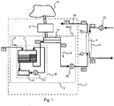
- FIG. 1 shows an exemplary embodiment of a dialysis device 2, which has an inflow 4 in order to direct a dialysis liquid in a flow direction 6 to a dialysis membrane 8.
- the dialysis device 2 also has an outlet 10 in order to drain a dialysate from the dialysis membrane 8 .
- a heat pump 12 is coupled to the inflow 4 and is designed to exchange heat energy between a heat reservoir 14 and the dialysis liquid in the inflow 4 .
- Outflow 10 is to be understood here as all devices or lines in which the dialysate after the dialysis process within the dialysis device 2 itself in the in figure 1 shown direction of flow 6 can be performed or transported.
- the inflow 4 of the dialysis machine 2 is to be understood as meaning any device or line within the dialysis machine 2 that is or can be used to conduct dialysis fluid or components of a dialysis fluid to the dialysis membrane 8 .
- the inflow 4 should also be understood in particular as a line system or one or more devices that carry or process dialysis fluid.
- the dialysis membrane 8 or a dialyzer 16 containing the dialysis membrane 8 is not part of the dialysis device 2 itself no cross-infection can occur with other patients.
- the dialyzer 16 has connections 18a and 18b in order to couple the inflow 4 and the outflow 10 of the dialysis machine 2 to the dialyzer 16, so that the dialysis liquid flows on one side (in 1 left) of the dialysis membrane 8 is passed through the dialyzer housing 16.
- Another blood circulation circuit which can include a blood pump 30, particularly in the case of veno-venous access in the patient, as is shown in 1 is shown.
- the heat pump 12 is, as in figure 1 shown coupled to the inflow or inlet 4 in such a way that heat energy can be exchanged between a heat reservoir 14 and the dialysis liquid in the inflow 4 by means of the heat pump 12 .
- the additional medium required for such an exchange of heat energy by means of a heat pump 12, which forms the heat reservoir, is in figure 1 shown only schematically.
- the heat pump 12 is coupled to the dialysis fluid in the inflow 4 by means of a heat exchanger 13 4 or the dialysis liquid or another liquid in the inflow 4 to be exchanged. This can be the case, for example, by means of radiation.
- the in figure 1 Dialysis device 2 shown a degassing device 20, which consists of a liquid reservoir 21, a degassing device 22 and a circulation pump 24.
- the inside figure 1 Circuit shown schematically within the degassing device 20 is used to degas the dialysis liquid, for which purpose it is first passed from a first partial reservoir within the liquid reservoir 21 via the degassing device 22 into a second partial reservoir.
- a feed pump 24 is provided which drives this partial circuit for the degassing.
- the degassed dialysis fluid is transported past the point at which the heat pump 12 is coupled to the inflow 4 .
- the heat pump 12 serves to heat the dialysate in the inflow 4 during dialysis, so that when it reaches the dialysis membrane 8 it is at least approximately at body temperature.
- the figure 1 The exemplary embodiment illustrated also has a further optional feed pump 28 which transports the dialysis liquid in the direction of the dialysis membrane 8 after it has been heated by means of the heat pump 12 .
- the delivered liquid or dialysis liquid can be delivered at a temperature of about 10°C.
- the temperature Before it flows through the external dialyzer 16, in the figure 1 illustrated embodiment increases the temperature to about 37 ° C. This is done by means of the heat pump 12, which takes the thermal energy required for this purpose from the heat reservoir 14.
- the degassing device 20 can also be arranged in the direction of flow 6 between a coupling point of the heat pump 12 and the dialysis membrane 8 or between the heat pump 12 and the feed pump 28 .
- the temperatures given are only to be understood as examples; any other temperatures are possible.
- the temperature of the water fed in or of the dialysis liquid at the beginning of the inflow 4 can also be significantly higher than 10° C., so that the ambient air can be used as the heat reservoir 14, for example.
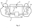
- the heat pump 12 is a machine that pumps heat from a heat source or a heat reservoir 14 to a medium 34 to be heated while supplying technical work.
- the heat pump was developed to pump thermal energy from a lower to a higher temperature level, so that the thermal energy contained in the medium at a lower temperature can be used to additionally heat a medium at a higher temperature, which would not be possible using normal heat exchangers.
- the heat pump 12 shown has a compressor or condenser 36 and an evaporator or an expansion valve 38 .
- a working medium often also referred to as refrigerant, circulates in a circulation direction 40 within a circuit driven by the compressor 36 .
- the compressor 36 can, for example, be driven electrically or by an internal combustion engine and causes the working medium to circulate within the circuit.
- the compressor 36 compresses the working medium or the refrigerant to a higher pressure, with the working medium, which is usually gaseous in front of the compressor 36, being heated and then liquefied. The energy released when the refrigerant is liquefied is transferred to the medium 34 to be heated in a heat exchanger 42b.
- a heat exchanger for example, can be used as the heat exchanger 42b.
- the heat can also be transferred to the medium to be heated by other mechanisms, for example by radiation.
- the heat pump 12 or the working medium in the exemplary embodiments of the invention is coupled to the medium 34 to be heated in such a way that an exchange of thermal energy is possible.
- the working medium or the refrigerant is expanded at a decompressor or at an expansion valve 38, where it cools down.
- the cold refrigerant is then fed to an evaporator 42a (water heat exchanger, geothermal probes, air evaporator) and changes to the gaseous state by absorbing ambient heat (anergy) from the heat source or from the heat reservoir 14 .
- evaporator 42a water heat exchanger, geothermal probes, air evaporator
- ambient heat ambient heat
- the ratio of usable heat output to the electrical power supplied is referred to as the performance number or in technical literature as the COP ("Coefficient of Performance") of the heat pump.
- the coefficient of performance has a theoretical maximum value that depends on the temperatures of the heat reservoir 14 and the medium 34 to be heated and can be derived from the Carnot process (named after Nicolas Leonard Sadi Carnot).
- the COP has a value of 8 or more. Values that can currently be achieved in practice are between 4 and 6. This means that 4 to 6 times the energy required to drive the heat pump 12 is transferred to the medium 34 to be heated Figures 3 and 4 , where, contrary to the usual mode of operation of the heat pump 12, thermal energy is transferred from a reservoir of higher temperature to a medium of lower temperature, the values achieved in practice are even higher because of this fact.
- This energy requirement can be significantly reduced when using a heat pump. Assuming that the entire energy used for the initial heating of the dialysis fluid in the inflow 4 would be removed from the dialysate in the outflow 10 by means of a Heat pump transferred to the dialysis fluid in the inflow 4, so that the dialysate in the outflow 10 would have approximately the same temperature as the dialysis fluid in the inflow 4 before heating, even with a minimum expected COP of 4, there is already an energy saving of 50%, since only a quarter of the thermal energy transferred must be used as energy to drive the heat pump. In the idealized example, the energy requirement can be reduced to less than 0.9 kWh. Taking into account the additional losses that actually occur in conventional dialysis machines, the increase in efficiency that can be achieved can be considerably higher.
- figure 3 shows another embodiment of a dialysis machine 2
- some components with the embodiment that is based on figure 1 was shown has in common. Therefore, in the following, only the differences to the in figure 1 embodiment shown in more detail.
- functionally similar or identical components are provided with the same reference symbols in the exemplary embodiments described herein.
- the components described with reference to the various exemplary embodiments and their functionality can also be arbitrarily exchanged within the individual exemplary embodiments.
- the heat pump 12 uses the dialysate in the outflow 10 as a heat reservoir.
- the heat pump 12 is coupled to the dialysate in the outflow 10, for example by means of a heat exchanger 44, in order to be able to use the outflowing dialysate as a heat reservoir.
- the compressor or compressor 36 contained in the heat pump 12 circulates the working medium of the heat pump 12 in the in figure 3 indicated direction to transfer thermal energy from the dialysate in the outflow 10 to the dialysis fluid in the inflow 4.
- the heat pump 12 can also transfer thermal energy from the dialysis liquid or a liquid in the inflow 4 in a second operating mode in which the working medium circulates in the other direction transferred to the dialysate or the liquid in the drain 10.
- This second mode of operation can be of great advantage during or after the cleaning of a dialysis machine.
- the dialysis device should reach a temperature of ⁇ 40 °C as quickly as possible so that the next treatment can begin.
- Hot disinfection is carried out with >85°C hot water to which disinfectant has been added. If a heat exchanger were used for energy recovery, the incoming fresh water would be undesirably heated by the heat exchanger when rinsing out the dialysis machine after disinfection, which would lengthen the rinsing phase. This reduction in efficiency is avoided when using a heat pump.
- a liquid in the inflow 4 can even be actively cooled, which leads to a further increase in efficiency.
- the use of a heat pump during the dialysis operation also has the advantage that the temperature of the dialysate emerging from the outflow 10 is lower than is conventionally the case. This is of great advantage in clinics, since it promotes bacterial growth in the drain or drain less than is the case when the dialysate draining has a temperature of 20° or more.
- FIG. 1 shows a further exemplary embodiment of a dialysis device, in which an additional heating device 50 is additionally coupled to the inflow 4 in order to heat the dialysis liquid in the inflow 4.
- the additional heating device 50 is arranged in the direction of flow 6 between the heat pump 12 and the dialysis membrane 8 in order to heat the dialysis liquid in the inflow 4 additionally and independently of the heat pump 12 .
- This can be used when starting up the dialysis machine to reduce the time required to heat the dialysis liquid to the required temperature if the dialysate in the outflow 10 does not yet have the temperature achieved in stationary operation at the beginning.
- an electric heater or a fast-regulating heater as the additional heating device 50, it can be ensured that the temperature of the dialysis fluid is within a required temperature window at all times.
- the additional heating device 50 can be coupled to the inflow 4 at any other point in order to heat the dialysis liquid in the inflow 4 .
- the additional heating device 50 can also be arranged between the feed pump 28 and the dialysis membrane 8 .
- the additional heating device 50 can also be arranged outside the circuit of the degassing device 20 .
- FIG 4 shows figure 4 an embodiment in which a heat pump 12 is used to provide the main heating capacity of the dialysis machine.
- a small heater is provided to achieve precise temperature control.
- the amount of incoming water or dialysis fluid and outgoing dialysate is largely the same. This means that if it is possible to make the heat from the waste water available to the inflow or inflow 4 via the heat pump 12, then only that which occurs as losses through convection or radiation must be supplied as differential energy.
- the heat pump 12 extracts in the evaporator on the outflow side, the energy as far as possible for the outflowing and used dialysate.
- the heat pump 12 compresses the coolant.
- the heat pump 12 On the other side of the heat circuit of the heat pump 12 sits a condenser in the water inlet or inflow. There, the energy is given off by the liquefaction to the inflowing water or the inflowing dialysis liquid. The heat pump 12 thus heats the incoming dialysis liquid with the energy extracted from the outlet. The temperature of the outflowing dialysate can even be below that of the inflowing water.
- the heater or additional heating device 50 can accelerate the heating-up phase at the beginning of the treatment when the water or the dialysate in the outflow or outflow 10 is not yet at operating temperature.
- the heater can also serve to increase the temperature control accuracy.
- a mixing valve or similar could also be used for temperature control.
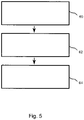
- figure 5 shows an example of a method for efficient operation of a dialysis machine.
- a dialysis fluid is supplied to a dialysis membrane 8 via an inflow 4 .
- a dialysate is drained from the dialysis membrane 8 via an outlet 10.
- the temperature control 64 the dialysis liquid fed to the dialysis membrane is temperature controlled with a heat pump 12 .
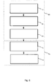
- figure 6 shows another example of a method for the efficient operation of a dialysis machine, which in a first operating mode 66 includes the steps in figure 5 comprises the method shown, wherein the dialysis membrane 8 supplied dialysis fluid is heated with the heat pump 12.
- the inflow 4 and the outflow 10 are cleaned during a cleaning 72 with a cleaning liquid flowing through the inflow 4 and the outflow 10 .
- a rinsing liquid or the dialysis liquid in the inflow 4 is cooled by means of the heat pump 12 operating in a second operating mode.
Landscapes
- Health & Medical Sciences (AREA)
- Heart & Thoracic Surgery (AREA)
- Urology & Nephrology (AREA)
- Vascular Medicine (AREA)
- Hematology (AREA)
- Engineering & Computer Science (AREA)
- Anesthesiology (AREA)
- Biomedical Technology (AREA)
- Life Sciences & Earth Sciences (AREA)
- Animal Behavior & Ethology (AREA)
- General Health & Medical Sciences (AREA)
- Public Health (AREA)
- Veterinary Medicine (AREA)
- Emergency Medicine (AREA)
- Cardiology (AREA)
- External Artificial Organs (AREA)
Claims (13)
- Dispositif de dialyse (2) comprenant les caractéristiques suivantes :un circuit d'acheminement (4) pour conduire un liquide de dialyse dans une direction d'écoulement (6) à une membrane de dialyse (8) ;un circuit d'évacuation (10) pour évacuer un dialysat de la membrane de dialyse (8),caractérisé par une pompe à chaleur (12) couplée au circuit d'acheminement (4) qui est conçue pour échanger de l'énergie thermique entre un réservoir de chaleur (14) et le liquide de dialyse dans le circuit d'acheminement (4), dans lequel le dispositif de dialyse (2) présente de plus un dispositif de dégazage (20) couplé au circuit d'acheminement (4) qui est conçu pour éliminer les gaz contenus dans le liquide de dialyse.
- Dispositif de dialyse (2) selon la revendication 1, pour lequel la pompe à chaleur (12) est conçue pour utiliser un air ambiant comme réservoir de chaleur (14).
- Dispositif de dialyse (2) selon la revendication 1, pour lequel la pompe à chaleur (12) est en outre couplée au circuit d'évacuation (10), dans lequel la pompe à chaleur (12) est conçue pour utiliser le dialysat dans le circuit d'évacuation (10) comme réservoir de chaleur (14).
- Dispositif de dialyse (2) selon l'une des revendications précédentes, dans lequel la pompe à chaleur (12) est conçue pour transmettre dans un premier mode de fonctionnement de l'énergie thermique du réservoir de chaleur (14) au liquide de dialyse dans le circuit d'acheminement (4) pour chauffer le liquide de dialyse.
- Dispositif de dialyse (2) selon l'une des revendications précédentes, dans lequel la pompe à chaleur (12) est conçue pour transmettre dans un deuxième mode de fonctionnement, de l'énergie thermique du liquide de dialyse dans le circuit d'acheminement (4) au réservoir de chaleur (14) pour refroidir le liquide de dialyse.
- Dispositif de dialyse (2) selon l'une des revendications précédentes, qui présente en outre dans le circuit d'acheminement (4) un système de chauffage d'addition (50) couplé au circuit d'acheminement (4) dans la direction d'écoulement (6) entre la pompe à chaleur (12) et la membrane de dialyse (8), qui est conçu pour réchauffer le liquide de dialyse dans le circuit d'acheminement (4).
- Dispositif de dialyse (2) selon la revendication 5, dans lequel le système de chauffage d'addition (50) est un chauffage actionné électriquement.
- Dispositif de dialyse (2) selon l'une des revendications précédentes, qui présente en outre une pompe d'alimentation (28) disposée dans la direction d'écoulement (6) entre la pompe à chaleur (12) et la membrane de dialyse (8).
- Dispositif de dialyse (2) selon la revendication 1, dans lequel le dispositif de dégazage (20) est couplé dans la direction d'écoulement (6) entre la pompe à chaleur (12) et la membrane de dialyse (8) ou dans la direction d'écoulement (6) avant la pompe à chaleur (12), au circuit d'acheminement (4).
- Dispositif de dialyse (2) selon l'une des revendications précédentes, qui présente en outre un dialyseur (16) comprenant une membrane de dialyse (8), dans lequel le circuit d'acheminement (4) et le circuit d'évacuation (10) sont couplés au dialyseur (16) et dans lequel se trouvent en outre sur le dialyseur (16), des raccords pour un acheminement et une évacuation d'un sang à purifier au moyen du dispositif de dialyse (2).
- Dispositif de dialyse (2) selon l'une des revendications précédentes, caractérisé en ce que le liquide de dialyse est acheminé à la membrane de dialyse (8) par le circuit d'acheminement (4), le dialysat est évacué de la membrane de dialyse (8) par le circuit d'évacuation (10) ; et que le liquide de dialyse acheminé à la membrane de dialyse (8) est tempéré avec la pompe à chaleur (12).
- Dispositif de dialyse (2) selon l'une des revendications précédentes, caractérisé en ce que dans un premier mode de fonctionnement, le liquide de dialyse acheminé à la membrane de dialyse (8) est chauffé grâce à la pompe à chaleur (12).
- Dispositif de dialyse (2) selon la revendication 12, caractérisé en ce que le circuit d'acheminement (4) et le circuit d'évacuation sont nettoyés au moyen d'un liquide de nettoyage parcourant le circuit d'acheminement (4) et le circuit d'évacuation et ensuite le dispositif de dialyse (2) est rincé, dans lequel, pendant le rinçage, dans un deuxième mode de fonctionnement, un liquide de rinçage ou le liquide de dialyse est refroidi dans le circuit d'acheminement (4) au moyen de la pompe à chaleur (12).
Priority Applications (4)
| Application Number | Priority Date | Filing Date | Title |
|---|---|---|---|
| EP11157528.8A EP2497507B2 (fr) | 2011-03-09 | 2011-03-09 | Dispositif de dialyse |
| CN201290000322.0U CN203619967U (zh) | 2011-03-09 | 2012-01-10 | 透析单元 |
| PCT/EP2012/050286 WO2012119799A1 (fr) | 2011-03-09 | 2012-01-10 | Dispositif de dialyse et procédé pour faire fonctionner un dispositif de dialyse |
| US14/003,325 US9265873B2 (en) | 2011-03-09 | 2012-01-10 | Dialysis device and method for operating a dialysis device |
Applications Claiming Priority (1)
| Application Number | Priority Date | Filing Date | Title |
|---|---|---|---|
| EP11157528.8A EP2497507B2 (fr) | 2011-03-09 | 2011-03-09 | Dispositif de dialyse |
Publications (3)
| Publication Number | Publication Date |
|---|---|
| EP2497507A1 EP2497507A1 (fr) | 2012-09-12 |
| EP2497507B1 EP2497507B1 (fr) | 2014-02-19 |
| EP2497507B2 true EP2497507B2 (fr) | 2022-09-14 |
Family
ID=44358127
Family Applications (1)
| Application Number | Title | Priority Date | Filing Date |
|---|---|---|---|
| EP11157528.8A Active EP2497507B2 (fr) | 2011-03-09 | 2011-03-09 | Dispositif de dialyse |
Country Status (4)
| Country | Link |
|---|---|
| US (1) | US9265873B2 (fr) |
| EP (1) | EP2497507B2 (fr) |
| CN (1) | CN203619967U (fr) |
| WO (1) | WO2012119799A1 (fr) |
Families Citing this family (24)
| Publication number | Priority date | Publication date | Assignee | Title |
|---|---|---|---|---|
| DE102011016508A1 (de) | 2011-04-08 | 2012-10-11 | Sorin Group Deutschland Gmbh | Temperiervorrichtung für den Einsatz in fluidbasierten Hyper-/Hypothermie-Systemen |
| WO2012175210A2 (fr) * | 2011-06-22 | 2012-12-27 | Fresenius Medical Care Deutschland Gmbh | Clinique de dialyse à émission zéro |
| ES2640953T3 (es) | 2011-10-07 | 2017-11-07 | Outset Medical, Inc. | Purificación de líquido de intercambio de calor para un sistema de diálisis |
| WO2014018798A2 (fr) | 2012-07-25 | 2014-01-30 | Nxstage Medical, Inc. | Dispositifs, procédés et systèmes de mesure de propriété de fluide |
| US9846085B2 (en) | 2012-07-25 | 2017-12-19 | Nxstage Medical, Inc. | Fluid property measurement devices, methods, and systems |
| EP2698176B1 (fr) * | 2012-08-13 | 2017-03-15 | Sorin Group Deutschland GmbH | Procédé et appareil de désinfection d'un dispositif de régulation de température pour la régulation de la température du corps humain pendant la circulation extra-corporelle |
| EP2698177B1 (fr) | 2012-08-13 | 2015-01-14 | Sorin Group Deutschland GmbH | Procédé pour commander un état de désinfection d'un dispositif de commande de température et dispositif de contrôle de température pour la régulation de la température du corps humain pendant une circulation extra-corporelle |
| AU2013201567B2 (en) | 2012-11-28 | 2015-12-17 | Gambro Lundia Ab | Systems, apparatus, equipment with thermal disinfection and thermal disinfection methods |
| DE102013107672A1 (de) | 2013-07-18 | 2015-01-22 | B. Braun Avitum Ag | Extrakorporale Blutbehandlungsanlage mit Wärmerückgewinnung |
| DE102013107673A1 (de) * | 2013-07-18 | 2015-01-22 | B. Braun Avitum Ag | Dialyseanlage mit Wärmerückgewinnung |
| CN104623751B (zh) | 2013-11-13 | 2017-04-12 | 甘布罗伦迪亚股份公司 | 透析监控器及操作方法 |
| CN104740707B (zh) | 2013-12-30 | 2018-06-01 | 甘布罗伦迪亚股份公司 | 透析机、控制透析机的方法 |
| WO2015168280A1 (fr) | 2014-04-29 | 2015-11-05 | Outset Medical, Inc. | Système et procédés de dialyse |
| KR101580439B1 (ko) * | 2014-05-08 | 2015-12-24 | 조태범 | 투석액 재생 장치 및 이를 갖는 혈액투석장치 |
| DE102015104430A1 (de) * | 2015-03-24 | 2016-09-29 | Fresenius Medical Care Deutschland Gmbh | Temperaturstörungsunabhängige Bilanzierungseinrichtung und Bilanzierungsverfahren |
| DE102015012604B4 (de) | 2015-09-28 | 2025-05-08 | Fresenius Medical Care Deutschland Gmbh | Dialysegerät |
| JP7025408B2 (ja) | 2016-08-19 | 2022-02-24 | アウトセット・メディカル・インコーポレイテッド | 腹膜透析システム及び方法 |
| EP3363481B1 (fr) | 2017-02-15 | 2020-05-13 | D.Med Consulting AG | Système d'hémodialyse |
| US10960124B2 (en) | 2018-07-06 | 2021-03-30 | Fresenius Medical Care Holdings, Inc. | Devices, systems, and methods for heating dialysate for dialysis machines |
| AU2019325668B2 (en) | 2018-08-23 | 2025-03-27 | Outset Medical, Inc. | Dialysis system and methods |
| DE102018121671B4 (de) * | 2018-09-05 | 2021-01-07 | Fresenius Medical Care Deutschland Gmbh | Medienversorgungseinrichtung zur Versorgung eines medizinischen Behandlungsgeräts |
| CN113795286A (zh) | 2019-04-30 | 2021-12-14 | 开端医疗公司 | 透析系统和方法 |
| US11806460B2 (en) | 2019-12-06 | 2023-11-07 | Fresenius Medical Care Holdings, Inc. | Syringe warmer |
| EP4168062A4 (fr) | 2020-06-23 | 2024-05-22 | NxStage Medical, Inc. | Dispositifs, méthodes, et systèmes d'isolation électrique |
Citations (1)
| Publication number | Priority date | Publication date | Assignee | Title |
|---|---|---|---|---|
| EP2595670A1 (fr) † | 2010-07-20 | 2013-05-29 | Fresenius Medical Care Deutschland GmbH | Système de chauffage d'un fluide médical, appareil médical fonctionnel, dispositif de traitement médical et procédés associés |
Family Cites Families (9)
| Publication number | Priority date | Publication date | Assignee | Title |
|---|---|---|---|---|
| US3515275A (en) | 1968-03-13 | 1970-06-02 | Donald B Bowman | Hemodialysis method and equipment |
| US3878095A (en) | 1974-05-02 | 1975-04-15 | Advanced Medical Sciences Inc | Dialysis apparatus |
| SE500294C2 (sv) * | 1989-11-16 | 1994-05-30 | Gambro Ab | Sätt respektive system för beredning av en steril dialysvätska |
| SE510026C2 (sv) | 1994-09-23 | 1999-04-12 | Gambro Ab | Desinficeringsanordning för dialysmaskin |
| SE510513C2 (sv) * | 1994-12-07 | 1999-05-31 | Gambro Lundia Ab | Förfarande och anordning för att mäta ultrafiltreringsvolymen i en dialysmaskin samt förfarande för kalibrering av anordningen |
| JP4125616B2 (ja) * | 2002-04-15 | 2008-07-30 | 日機装株式会社 | 血液浄化装置 |
| MX362903B (es) | 2006-04-14 | 2019-02-22 | Deka Products Lp Star | Sistemas, dispositivos y metodos para bombeo de fluido, intercambio de calor, deteccion termica y deteccion de conductividad. |
| US7694514B2 (en) | 2007-08-08 | 2010-04-13 | Cool Energy, Inc. | Direct contact thermal exchange heat engine or heat pump |
| WO2010040827A1 (fr) | 2008-10-10 | 2010-04-15 | Gambro Lundia Ab | Échangeur de chaleur et procédé d'échange de chaleur |
-
2011
- 2011-03-09 EP EP11157528.8A patent/EP2497507B2/fr active Active
-
2012
- 2012-01-10 CN CN201290000322.0U patent/CN203619967U/zh not_active Expired - Lifetime
- 2012-01-10 US US14/003,325 patent/US9265873B2/en active Active
- 2012-01-10 WO PCT/EP2012/050286 patent/WO2012119799A1/fr not_active Ceased
Patent Citations (1)
| Publication number | Priority date | Publication date | Assignee | Title |
|---|---|---|---|---|
| EP2595670A1 (fr) † | 2010-07-20 | 2013-05-29 | Fresenius Medical Care Deutschland GmbH | Système de chauffage d'un fluide médical, appareil médical fonctionnel, dispositif de traitement médical et procédés associés |
Also Published As
| Publication number | Publication date |
|---|---|
| CN203619967U (zh) | 2014-06-04 |
| WO2012119799A1 (fr) | 2012-09-13 |
| US9265873B2 (en) | 2016-02-23 |
| EP2497507B1 (fr) | 2014-02-19 |
| EP2497507A1 (fr) | 2012-09-12 |
| US20140014580A1 (en) | 2014-01-16 |
Similar Documents
| Publication | Publication Date | Title |
|---|---|---|
| EP2497507B2 (fr) | Dispositif de dialyse | |
| DE69929555T2 (de) | Verwendung einer Flüssigkeit zur Herstellung einer Dialyselösung für die kontinuierliche rezirkulierende Peritonealdialyse | |
| DE60127657T2 (de) | Blutreinigungssystem | |
| EP2745861B1 (fr) | Machine de nettoyage du sang avec circuit de liquide chauffé | |
| EP1867354B1 (fr) | Dispositif destiné à l'enlèvement de substances liées aux protéines | |
| EP2826504B1 (fr) | Installation de traitement du sang extra-corporel dotée d'une récupération de chaleur | |
| WO2001047580A1 (fr) | Systeme d'hemodiafiltration | |
| JPH0714511B2 (ja) | 半導体製造ライン用純水製造装置 | |
| EP4096737B1 (fr) | Dispositif et méthode pour préparer du dialysat | |
| DE102018105120A1 (de) | Vorrichtung und Verfahren zur Regeneration einer Dialyselösung | |
| EP2826505B1 (fr) | Installation de dialyse dotée d'une récupération de chaleur | |
| EP3829676B1 (fr) | Dispositif pour la régénération du dialysat utilisé | |
| EP3377140B1 (fr) | Appareil de dialyse présentant un mécanisme de chauffage et de refroidissement | |
| DE19933223B4 (de) | Verfahren zur thermischen Desinfektion von Hämodialyseanlagen | |
| DE102017001770B4 (de) | Extrakorporale Blutbehandlungsvorrichtung zum Betreiben einer extrakorporalen Blutbehandlungsvorrichtung | |
| DE1960504A1 (de) | Behandlung einer Dialysatloesung zwecks Entfernung von Harnstoff | |
| EP3609551A1 (fr) | Dispositif de traitement extracorporel du sang et procédé de fonctionnement d'un dispositif de traitement extracorporel du sang | |
| EP4599861B1 (fr) | Unité de dialyse et procédé de préparation d'une thérapie de dialyse | |
| DE102024117910A1 (de) | Vorrichtung und Verfahren zur Produktion von Permeat, insbesondere für eine Dialysetherapie | |
| DE102024103544A1 (de) | System und Verfahren zur thermischen Desinfektion einer Umkehrosmoseanlage | |
| EP4468308A1 (fr) | Procédé de fonctionnement d'un système de dialyse | |
| EP4623946A1 (fr) | Système comprenant un dispositif de traitement extracorporel du sang et un échangeur de chaleur | |
| DE7013380U (de) | Vorrichtung zur dialyse von menschlichen blut. |
Legal Events
| Date | Code | Title | Description |
|---|---|---|---|
| PUAI | Public reference made under article 153(3) epc to a published international application that has entered the european phase |
Free format text: ORIGINAL CODE: 0009012 |
|
| 17P | Request for examination filed |
Effective date: 20111222 |
|
| AK | Designated contracting states |
Kind code of ref document: A1 Designated state(s): AL AT BE BG CH CY CZ DE DK EE ES FI FR GB GR HR HU IE IS IT LI LT LU LV MC MK MT NL NO PL PT RO RS SE SI SK SM TR |
|
| AX | Request for extension of the european patent |
Extension state: BA ME |
|
| 17Q | First examination report despatched |
Effective date: 20121114 |
|
| GRAP | Despatch of communication of intention to grant a patent |
Free format text: ORIGINAL CODE: EPIDOSNIGR1 |
|
| INTG | Intention to grant announced |
Effective date: 20130807 |
|
| GRAS | Grant fee paid |
Free format text: ORIGINAL CODE: EPIDOSNIGR3 |
|
| GRAA | (expected) grant |
Free format text: ORIGINAL CODE: 0009210 |
|
| AK | Designated contracting states |
Kind code of ref document: B1 Designated state(s): AL AT BE BG CH CY CZ DE DK EE ES FI FR GB GR HR HU IE IS IT LI LT LU LV MC MK MT NL NO PL PT RO RS SE SI SK SM TR |
|
| REG | Reference to a national code |
Ref country code: GB Ref legal event code: FG4D Free format text: NOT ENGLISH |
|
| REG | Reference to a national code |
Ref country code: CH Ref legal event code: EP |
|
| REG | Reference to a national code |
Ref country code: AT Ref legal event code: REF Ref document number: 652688 Country of ref document: AT Kind code of ref document: T Effective date: 20140315 |
|
| REG | Reference to a national code |
Ref country code: DE Ref legal event code: R096 Ref document number: 502011002159 Country of ref document: DE Effective date: 20140403 |
|
| REG | Reference to a national code |
Ref country code: IE Ref legal event code: FG4D Free format text: LANGUAGE OF EP DOCUMENT: GERMAN |
|
| REG | Reference to a national code |
Ref country code: NL Ref legal event code: VDEP Effective date: 20140219 |
|
| REG | Reference to a national code |
Ref country code: LT Ref legal event code: MG4D |
|
| PG25 | Lapsed in a contracting state [announced via postgrant information from national office to epo] |
Ref country code: LT Free format text: LAPSE BECAUSE OF FAILURE TO SUBMIT A TRANSLATION OF THE DESCRIPTION OR TO PAY THE FEE WITHIN THE PRESCRIBED TIME-LIMIT Effective date: 20140219 Ref country code: NO Free format text: LAPSE BECAUSE OF FAILURE TO SUBMIT A TRANSLATION OF THE DESCRIPTION OR TO PAY THE FEE WITHIN THE PRESCRIBED TIME-LIMIT Effective date: 20140519 Ref country code: IS Free format text: LAPSE BECAUSE OF FAILURE TO SUBMIT A TRANSLATION OF THE DESCRIPTION OR TO PAY THE FEE WITHIN THE PRESCRIBED TIME-LIMIT Effective date: 20140619 |
|
| PG25 | Lapsed in a contracting state [announced via postgrant information from national office to epo] |
Ref country code: ES Free format text: LAPSE BECAUSE OF FAILURE TO SUBMIT A TRANSLATION OF THE DESCRIPTION OR TO PAY THE FEE WITHIN THE PRESCRIBED TIME-LIMIT Effective date: 20140219 Ref country code: SE Free format text: LAPSE BECAUSE OF FAILURE TO SUBMIT A TRANSLATION OF THE DESCRIPTION OR TO PAY THE FEE WITHIN THE PRESCRIBED TIME-LIMIT Effective date: 20140219 Ref country code: PT Free format text: LAPSE BECAUSE OF FAILURE TO SUBMIT A TRANSLATION OF THE DESCRIPTION OR TO PAY THE FEE WITHIN THE PRESCRIBED TIME-LIMIT Effective date: 20140619 Ref country code: FI Free format text: LAPSE BECAUSE OF FAILURE TO SUBMIT A TRANSLATION OF THE DESCRIPTION OR TO PAY THE FEE WITHIN THE PRESCRIBED TIME-LIMIT Effective date: 20140219 Ref country code: NL Free format text: LAPSE BECAUSE OF FAILURE TO SUBMIT A TRANSLATION OF THE DESCRIPTION OR TO PAY THE FEE WITHIN THE PRESCRIBED TIME-LIMIT Effective date: 20140219 Ref country code: CY Free format text: LAPSE BECAUSE OF FAILURE TO SUBMIT A TRANSLATION OF THE DESCRIPTION OR TO PAY THE FEE WITHIN THE PRESCRIBED TIME-LIMIT Effective date: 20140219 |
|
| PG25 | Lapsed in a contracting state [announced via postgrant information from national office to epo] |
Ref country code: LV Free format text: LAPSE BECAUSE OF FAILURE TO SUBMIT A TRANSLATION OF THE DESCRIPTION OR TO PAY THE FEE WITHIN THE PRESCRIBED TIME-LIMIT Effective date: 20140219 Ref country code: RS Free format text: LAPSE BECAUSE OF FAILURE TO SUBMIT A TRANSLATION OF THE DESCRIPTION OR TO PAY THE FEE WITHIN THE PRESCRIBED TIME-LIMIT Effective date: 20140219 Ref country code: HR Free format text: LAPSE BECAUSE OF FAILURE TO SUBMIT A TRANSLATION OF THE DESCRIPTION OR TO PAY THE FEE WITHIN THE PRESCRIBED TIME-LIMIT Effective date: 20140219 |
|
| PG25 | Lapsed in a contracting state [announced via postgrant information from national office to epo] |
Ref country code: RO Free format text: LAPSE BECAUSE OF FAILURE TO SUBMIT A TRANSLATION OF THE DESCRIPTION OR TO PAY THE FEE WITHIN THE PRESCRIBED TIME-LIMIT Effective date: 20140219 Ref country code: CZ Free format text: LAPSE BECAUSE OF FAILURE TO SUBMIT A TRANSLATION OF THE DESCRIPTION OR TO PAY THE FEE WITHIN THE PRESCRIBED TIME-LIMIT Effective date: 20140219 Ref country code: EE Free format text: LAPSE BECAUSE OF FAILURE TO SUBMIT A TRANSLATION OF THE DESCRIPTION OR TO PAY THE FEE WITHIN THE PRESCRIBED TIME-LIMIT Effective date: 20140219 Ref country code: DK Free format text: LAPSE BECAUSE OF FAILURE TO SUBMIT A TRANSLATION OF THE DESCRIPTION OR TO PAY THE FEE WITHIN THE PRESCRIBED TIME-LIMIT Effective date: 20140219 |
|
| REG | Reference to a national code |
Ref country code: CH Ref legal event code: PL |
|
| REG | Reference to a national code |
Ref country code: DE Ref legal event code: R026 Ref document number: 502011002159 Country of ref document: DE |
|
| PG25 | Lapsed in a contracting state [announced via postgrant information from national office to epo] |
Ref country code: MC Free format text: LAPSE BECAUSE OF FAILURE TO SUBMIT A TRANSLATION OF THE DESCRIPTION OR TO PAY THE FEE WITHIN THE PRESCRIBED TIME-LIMIT Effective date: 20140219 Ref country code: SK Free format text: LAPSE BECAUSE OF FAILURE TO SUBMIT A TRANSLATION OF THE DESCRIPTION OR TO PAY THE FEE WITHIN THE PRESCRIBED TIME-LIMIT Effective date: 20140219 Ref country code: PL Free format text: LAPSE BECAUSE OF FAILURE TO SUBMIT A TRANSLATION OF THE DESCRIPTION OR TO PAY THE FEE WITHIN THE PRESCRIBED TIME-LIMIT Effective date: 20140219 |
|
| PLBI | Opposition filed |
Free format text: ORIGINAL CODE: 0009260 |
|
| 26 | Opposition filed |
Opponent name: FRESENIUS MEDICAL CARE AG & CO. KGAA Effective date: 20141119 |
|
| REG | Reference to a national code |
Ref country code: IE Ref legal event code: MM4A |
|
| PLAX | Notice of opposition and request to file observation + time limit sent |
Free format text: ORIGINAL CODE: EPIDOSNOBS2 |
|
| PG25 | Lapsed in a contracting state [announced via postgrant information from national office to epo] |
Ref country code: IE Free format text: LAPSE BECAUSE OF NON-PAYMENT OF DUE FEES Effective date: 20140309 Ref country code: CH Free format text: LAPSE BECAUSE OF NON-PAYMENT OF DUE FEES Effective date: 20140331 Ref country code: LI Free format text: LAPSE BECAUSE OF NON-PAYMENT OF DUE FEES Effective date: 20140331 |
|
| REG | Reference to a national code |
Ref country code: DE Ref legal event code: R026 Ref document number: 502011002159 Country of ref document: DE Effective date: 20141119 |
|
| PG25 | Lapsed in a contracting state [announced via postgrant information from national office to epo] |
Ref country code: RS Free format text: LAPSE BECAUSE OF FAILURE TO SUBMIT A TRANSLATION OF THE DESCRIPTION OR TO PAY THE FEE WITHIN THE PRESCRIBED TIME-LIMIT Effective date: 20140903 |
|
| REG | Reference to a national code |
Ref country code: FR Ref legal event code: PLFP Year of fee payment: 5 |
|
| PG25 | Lapsed in a contracting state [announced via postgrant information from national office to epo] |
Ref country code: IT Free format text: LAPSE BECAUSE OF FAILURE TO SUBMIT A TRANSLATION OF THE DESCRIPTION OR TO PAY THE FEE WITHIN THE PRESCRIBED TIME-LIMIT Effective date: 20140219 |
|
| PLBB | Reply of patent proprietor to notice(s) of opposition received |
Free format text: ORIGINAL CODE: EPIDOSNOBS3 |
|
| PG25 | Lapsed in a contracting state [announced via postgrant information from national office to epo] |
Ref country code: SI Free format text: LAPSE BECAUSE OF FAILURE TO SUBMIT A TRANSLATION OF THE DESCRIPTION OR TO PAY THE FEE WITHIN THE PRESCRIBED TIME-LIMIT Effective date: 20140219 |
|
| PG25 | Lapsed in a contracting state [announced via postgrant information from national office to epo] |
Ref country code: MT Free format text: LAPSE BECAUSE OF FAILURE TO SUBMIT A TRANSLATION OF THE DESCRIPTION OR TO PAY THE FEE WITHIN THE PRESCRIBED TIME-LIMIT Effective date: 20140219 |
|
| REG | Reference to a national code |
Ref country code: FR Ref legal event code: PLFP Year of fee payment: 6 |
|
| PG25 | Lapsed in a contracting state [announced via postgrant information from national office to epo] |
Ref country code: SM Free format text: LAPSE BECAUSE OF FAILURE TO SUBMIT A TRANSLATION OF THE DESCRIPTION OR TO PAY THE FEE WITHIN THE PRESCRIBED TIME-LIMIT Effective date: 20140219 |
|
| PG25 | Lapsed in a contracting state [announced via postgrant information from national office to epo] |
Ref country code: BG Free format text: LAPSE BECAUSE OF FAILURE TO SUBMIT A TRANSLATION OF THE DESCRIPTION OR TO PAY THE FEE WITHIN THE PRESCRIBED TIME-LIMIT Effective date: 20140219 Ref country code: GR Free format text: LAPSE BECAUSE OF FAILURE TO SUBMIT A TRANSLATION OF THE DESCRIPTION OR TO PAY THE FEE WITHIN THE PRESCRIBED TIME-LIMIT Effective date: 20140520 |
|
| PG25 | Lapsed in a contracting state [announced via postgrant information from national office to epo] |
Ref country code: LU Free format text: LAPSE BECAUSE OF NON-PAYMENT OF DUE FEES Effective date: 20140309 Ref country code: BE Free format text: LAPSE BECAUSE OF FAILURE TO SUBMIT A TRANSLATION OF THE DESCRIPTION OR TO PAY THE FEE WITHIN THE PRESCRIBED TIME-LIMIT Effective date: 20140331 Ref country code: TR Free format text: LAPSE BECAUSE OF FAILURE TO SUBMIT A TRANSLATION OF THE DESCRIPTION OR TO PAY THE FEE WITHIN THE PRESCRIBED TIME-LIMIT Effective date: 20140219 Ref country code: HU Free format text: LAPSE BECAUSE OF FAILURE TO SUBMIT A TRANSLATION OF THE DESCRIPTION OR TO PAY THE FEE WITHIN THE PRESCRIBED TIME-LIMIT; INVALID AB INITIO Effective date: 20110309 |
|
| APBM | Appeal reference recorded |
Free format text: ORIGINAL CODE: EPIDOSNREFNO |
|
| APBP | Date of receipt of notice of appeal recorded |
Free format text: ORIGINAL CODE: EPIDOSNNOA2O |
|
| APAH | Appeal reference modified |
Free format text: ORIGINAL CODE: EPIDOSCREFNO |
|
| APBM | Appeal reference recorded |
Free format text: ORIGINAL CODE: EPIDOSNREFNO |
|
| APBP | Date of receipt of notice of appeal recorded |
Free format text: ORIGINAL CODE: EPIDOSNNOA2O |
|
| APBQ | Date of receipt of statement of grounds of appeal recorded |
Free format text: ORIGINAL CODE: EPIDOSNNOA3O |
|
| APBQ | Date of receipt of statement of grounds of appeal recorded |
Free format text: ORIGINAL CODE: EPIDOSNNOA3O |
|
| REG | Reference to a national code |
Ref country code: FR Ref legal event code: PLFP Year of fee payment: 7 |
|
| REG | Reference to a national code |
Ref country code: AT Ref legal event code: MM01 Ref document number: 652688 Country of ref document: AT Kind code of ref document: T Effective date: 20160309 |
|
| PG25 | Lapsed in a contracting state [announced via postgrant information from national office to epo] |
Ref country code: AT Free format text: LAPSE BECAUSE OF NON-PAYMENT OF DUE FEES Effective date: 20160309 |
|
| REG | Reference to a national code |
Ref country code: FR Ref legal event code: PLFP Year of fee payment: 8 |
|
| PG25 | Lapsed in a contracting state [announced via postgrant information from national office to epo] |
Ref country code: MK Free format text: LAPSE BECAUSE OF FAILURE TO SUBMIT A TRANSLATION OF THE DESCRIPTION OR TO PAY THE FEE WITHIN THE PRESCRIBED TIME-LIMIT Effective date: 20140219 |
|
| PG25 | Lapsed in a contracting state [announced via postgrant information from national office to epo] |
Ref country code: AL Free format text: LAPSE BECAUSE OF FAILURE TO SUBMIT A TRANSLATION OF THE DESCRIPTION OR TO PAY THE FEE WITHIN THE PRESCRIBED TIME-LIMIT Effective date: 20140219 |
|
| APBU | Appeal procedure closed |
Free format text: ORIGINAL CODE: EPIDOSNNOA9O |
|
| PUAH | Patent maintained in amended form |
Free format text: ORIGINAL CODE: 0009272 |
|
| STAA | Information on the status of an ep patent application or granted ep patent |
Free format text: STATUS: PATENT MAINTAINED AS AMENDED |
|
| 27A | Patent maintained in amended form |
Effective date: 20220914 |
|
| AK | Designated contracting states |
Kind code of ref document: B2 Designated state(s): AL AT BE BG CH CY CZ DE DK EE ES FI FR GB GR HR HU IE IS IT LI LT LU LV MC MK MT NL NO PL PT RO RS SE SI SK SM TR |
|
| REG | Reference to a national code |
Ref country code: DE Ref legal event code: R102 Ref document number: 502011002159 Country of ref document: DE |
|
| PGFP | Annual fee paid to national office [announced via postgrant information from national office to epo] |
Ref country code: DE Payment date: 20250319 Year of fee payment: 15 |
|
| PGFP | Annual fee paid to national office [announced via postgrant information from national office to epo] |
Ref country code: FR Payment date: 20250324 Year of fee payment: 15 |
|
| PGFP | Annual fee paid to national office [announced via postgrant information from national office to epo] |
Ref country code: GB Payment date: 20250324 Year of fee payment: 15 |