EP2497621A2 - Verfahren zum Betreiben einer Schweißvorrichtung, insbesondere eines wärmeimpulsgesteuerten und/oder dauerbeheizten Folienschweiß- und/oder Heißsiegelgerätes mit vorwählbarer elektronischer, prozessorgesteuerter Anpreßdruck- und Temperaturregelung und Vorrichtung hierzu - Google Patents
Verfahren zum Betreiben einer Schweißvorrichtung, insbesondere eines wärmeimpulsgesteuerten und/oder dauerbeheizten Folienschweiß- und/oder Heißsiegelgerätes mit vorwählbarer elektronischer, prozessorgesteuerter Anpreßdruck- und Temperaturregelung und Vorrichtung hierzu Download PDFInfo
- Publication number
- EP2497621A2 EP2497621A2 EP12157689A EP12157689A EP2497621A2 EP 2497621 A2 EP2497621 A2 EP 2497621A2 EP 12157689 A EP12157689 A EP 12157689A EP 12157689 A EP12157689 A EP 12157689A EP 2497621 A2 EP2497621 A2 EP 2497621A2
- Authority
- EP
- European Patent Office
- Prior art keywords
- welding
- preselected
- heat
- pressure
- operating
- Prior art date
- Legal status (The legal status is an assumption and is not a legal conclusion. Google has not performed a legal analysis and makes no representation as to the accuracy of the status listed.)
- Granted
Links
Images

Classifications
-
- B—PERFORMING OPERATIONS; TRANSPORTING
- B29—WORKING OF PLASTICS; WORKING OF SUBSTANCES IN A PLASTIC STATE IN GENERAL
- B29C—SHAPING OR JOINING OF PLASTICS; SHAPING OF MATERIAL IN A PLASTIC STATE, NOT OTHERWISE PROVIDED FOR; AFTER-TREATMENT OF THE SHAPED PRODUCTS, e.g. REPAIRING
- B29C66/00—General aspects of processes or apparatus for joining preformed parts
- B29C66/80—General aspects of machine operations or constructions and parts thereof
- B29C66/83—General aspects of machine operations or constructions and parts thereof characterised by the movement of the joining or pressing tools
- B29C66/832—Reciprocating joining or pressing tools
- B29C66/8322—Joining or pressing tools reciprocating along one axis
-
- B—PERFORMING OPERATIONS; TRANSPORTING
- B29—WORKING OF PLASTICS; WORKING OF SUBSTANCES IN A PLASTIC STATE IN GENERAL
- B29C—SHAPING OR JOINING OF PLASTICS; SHAPING OF MATERIAL IN A PLASTIC STATE, NOT OTHERWISE PROVIDED FOR; AFTER-TREATMENT OF THE SHAPED PRODUCTS, e.g. REPAIRING
- B29C65/00—Joining or sealing of preformed parts, e.g. welding of plastics materials; Apparatus therefor
- B29C65/02—Joining or sealing of preformed parts, e.g. welding of plastics materials; Apparatus therefor by heating, with or without pressure
- B29C65/18—Joining or sealing of preformed parts, e.g. welding of plastics materials; Apparatus therefor by heating, with or without pressure using heated tools
- B29C65/22—Heated wire resistive ribbon, resistive band or resistive strip
- B29C65/221—Heated wire resistive ribbon, resistive band or resistive strip characterised by the type of heated wire, resistive ribbon, band or strip
- B29C65/224—Heated wire resistive ribbon, resistive band or resistive strip characterised by the type of heated wire, resistive ribbon, band or strip being a resistive ribbon, a resistive band or a resistive strip
-
- B—PERFORMING OPERATIONS; TRANSPORTING
- B29—WORKING OF PLASTICS; WORKING OF SUBSTANCES IN A PLASTIC STATE IN GENERAL
- B29C—SHAPING OR JOINING OF PLASTICS; SHAPING OF MATERIAL IN A PLASTIC STATE, NOT OTHERWISE PROVIDED FOR; AFTER-TREATMENT OF THE SHAPED PRODUCTS, e.g. REPAIRING
- B29C66/00—General aspects of processes or apparatus for joining preformed parts
- B29C66/01—General aspects dealing with the joint area or with the area to be joined
- B29C66/05—Particular design of joint configurations
- B29C66/10—Particular design of joint configurations particular design of the joint cross-sections
- B29C66/11—Joint cross-sections comprising a single joint-segment, i.e. one of the parts to be joined comprising a single joint-segment in the joint cross-section
- B29C66/112—Single lapped joints
- B29C66/1122—Single lap to lap joints, i.e. overlap joints
-
- B—PERFORMING OPERATIONS; TRANSPORTING
- B29—WORKING OF PLASTICS; WORKING OF SUBSTANCES IN A PLASTIC STATE IN GENERAL
- B29C—SHAPING OR JOINING OF PLASTICS; SHAPING OF MATERIAL IN A PLASTIC STATE, NOT OTHERWISE PROVIDED FOR; AFTER-TREATMENT OF THE SHAPED PRODUCTS, e.g. REPAIRING
- B29C66/00—General aspects of processes or apparatus for joining preformed parts
- B29C66/40—General aspects of joining substantially flat articles, e.g. plates, sheets or web-like materials; Making flat seams in tubular or hollow articles; Joining single elements to substantially flat surfaces
- B29C66/41—Joining substantially flat articles ; Making flat seams in tubular or hollow articles
- B29C66/43—Joining a relatively small portion of the surface of said articles
- B29C66/431—Joining the articles to themselves
- B29C66/4312—Joining the articles to themselves for making flat seams in tubular or hollow articles, e.g. transversal seams
-
- B—PERFORMING OPERATIONS; TRANSPORTING
- B29—WORKING OF PLASTICS; WORKING OF SUBSTANCES IN A PLASTIC STATE IN GENERAL
- B29C—SHAPING OR JOINING OF PLASTICS; SHAPING OF MATERIAL IN A PLASTIC STATE, NOT OTHERWISE PROVIDED FOR; AFTER-TREATMENT OF THE SHAPED PRODUCTS, e.g. REPAIRING
- B29C66/00—General aspects of processes or apparatus for joining preformed parts
- B29C66/80—General aspects of machine operations or constructions and parts thereof
- B29C66/87—Auxiliary operations or devices
- B29C66/872—Starting or stopping procedures
-
- B—PERFORMING OPERATIONS; TRANSPORTING
- B29—WORKING OF PLASTICS; WORKING OF SUBSTANCES IN A PLASTIC STATE IN GENERAL
- B29C—SHAPING OR JOINING OF PLASTICS; SHAPING OF MATERIAL IN A PLASTIC STATE, NOT OTHERWISE PROVIDED FOR; AFTER-TREATMENT OF THE SHAPED PRODUCTS, e.g. REPAIRING
- B29C66/00—General aspects of processes or apparatus for joining preformed parts
- B29C66/80—General aspects of machine operations or constructions and parts thereof
- B29C66/87—Auxiliary operations or devices
- B29C66/874—Safety measures or devices
- B29C66/8742—Safety measures or devices for operators
-
- B—PERFORMING OPERATIONS; TRANSPORTING
- B29—WORKING OF PLASTICS; WORKING OF SUBSTANCES IN A PLASTIC STATE IN GENERAL
- B29C—SHAPING OR JOINING OF PLASTICS; SHAPING OF MATERIAL IN A PLASTIC STATE, NOT OTHERWISE PROVIDED FOR; AFTER-TREATMENT OF THE SHAPED PRODUCTS, e.g. REPAIRING
- B29C66/00—General aspects of processes or apparatus for joining preformed parts
- B29C66/80—General aspects of machine operations or constructions and parts thereof
- B29C66/87—Auxiliary operations or devices
- B29C66/874—Safety measures or devices
- B29C66/8744—Preventing overheating of the parts to be joined, e.g. if the machine stops or slows down
- B29C66/87443—Preventing overheating of the parts to be joined, e.g. if the machine stops or slows down by withdrawing the heating tools
-
- B—PERFORMING OPERATIONS; TRANSPORTING
- B29—WORKING OF PLASTICS; WORKING OF SUBSTANCES IN A PLASTIC STATE IN GENERAL
- B29C—SHAPING OR JOINING OF PLASTICS; SHAPING OF MATERIAL IN A PLASTIC STATE, NOT OTHERWISE PROVIDED FOR; AFTER-TREATMENT OF THE SHAPED PRODUCTS, e.g. REPAIRING
- B29C66/00—General aspects of processes or apparatus for joining preformed parts
- B29C66/90—Measuring or controlling the joining process
- B29C66/92—Measuring or controlling the joining process by measuring or controlling the pressure, the force, the mechanical power or the displacement of the joining tools
- B29C66/922—Measuring or controlling the joining process by measuring or controlling the pressure, the force, the mechanical power or the displacement of the joining tools by measuring the pressure, the force, the mechanical power or the displacement of the joining tools
- B29C66/9221—Measuring or controlling the joining process by measuring or controlling the pressure, the force, the mechanical power or the displacement of the joining tools by measuring the pressure, the force, the mechanical power or the displacement of the joining tools by measuring the pressure, the force or the mechanical power
- B29C66/92211—Measuring or controlling the joining process by measuring or controlling the pressure, the force, the mechanical power or the displacement of the joining tools by measuring the pressure, the force, the mechanical power or the displacement of the joining tools by measuring the pressure, the force or the mechanical power with special measurement means or methods
-
- B—PERFORMING OPERATIONS; TRANSPORTING
- B29—WORKING OF PLASTICS; WORKING OF SUBSTANCES IN A PLASTIC STATE IN GENERAL
- B29C—SHAPING OR JOINING OF PLASTICS; SHAPING OF MATERIAL IN A PLASTIC STATE, NOT OTHERWISE PROVIDED FOR; AFTER-TREATMENT OF THE SHAPED PRODUCTS, e.g. REPAIRING
- B29C66/00—General aspects of processes or apparatus for joining preformed parts
- B29C66/90—Measuring or controlling the joining process
- B29C66/92—Measuring or controlling the joining process by measuring or controlling the pressure, the force, the mechanical power or the displacement of the joining tools
- B29C66/922—Measuring or controlling the joining process by measuring or controlling the pressure, the force, the mechanical power or the displacement of the joining tools by measuring the pressure, the force, the mechanical power or the displacement of the joining tools
- B29C66/9231—Measuring or controlling the joining process by measuring or controlling the pressure, the force, the mechanical power or the displacement of the joining tools by measuring the pressure, the force, the mechanical power or the displacement of the joining tools by measuring the displacement of the joining tools
- B29C66/92311—Measuring or controlling the joining process by measuring or controlling the pressure, the force, the mechanical power or the displacement of the joining tools by measuring the pressure, the force, the mechanical power or the displacement of the joining tools by measuring the displacement of the joining tools with special measurement means or methods
-
- B—PERFORMING OPERATIONS; TRANSPORTING
- B29—WORKING OF PLASTICS; WORKING OF SUBSTANCES IN A PLASTIC STATE IN GENERAL
- B29C—SHAPING OR JOINING OF PLASTICS; SHAPING OF MATERIAL IN A PLASTIC STATE, NOT OTHERWISE PROVIDED FOR; AFTER-TREATMENT OF THE SHAPED PRODUCTS, e.g. REPAIRING
- B29C66/00—General aspects of processes or apparatus for joining preformed parts
- B29C66/90—Measuring or controlling the joining process
- B29C66/92—Measuring or controlling the joining process by measuring or controlling the pressure, the force, the mechanical power or the displacement of the joining tools
- B29C66/924—Measuring or controlling the joining process by measuring or controlling the pressure, the force, the mechanical power or the displacement of the joining tools by controlling or regulating the pressure, the force, the mechanical power or the displacement of the joining tools
- B29C66/9241—Measuring or controlling the joining process by measuring or controlling the pressure, the force, the mechanical power or the displacement of the joining tools by controlling or regulating the pressure, the force, the mechanical power or the displacement of the joining tools by controlling or regulating the pressure, the force or the mechanical power
-
- B—PERFORMING OPERATIONS; TRANSPORTING
- B29—WORKING OF PLASTICS; WORKING OF SUBSTANCES IN A PLASTIC STATE IN GENERAL
- B29C—SHAPING OR JOINING OF PLASTICS; SHAPING OF MATERIAL IN A PLASTIC STATE, NOT OTHERWISE PROVIDED FOR; AFTER-TREATMENT OF THE SHAPED PRODUCTS, e.g. REPAIRING
- B29C66/00—General aspects of processes or apparatus for joining preformed parts
- B29C66/90—Measuring or controlling the joining process
- B29C66/92—Measuring or controlling the joining process by measuring or controlling the pressure, the force, the mechanical power or the displacement of the joining tools
- B29C66/924—Measuring or controlling the joining process by measuring or controlling the pressure, the force, the mechanical power or the displacement of the joining tools by controlling or regulating the pressure, the force, the mechanical power or the displacement of the joining tools
- B29C66/9261—Measuring or controlling the joining process by measuring or controlling the pressure, the force, the mechanical power or the displacement of the joining tools by controlling or regulating the pressure, the force, the mechanical power or the displacement of the joining tools by controlling or regulating the displacement of the joining tools
- B29C66/92611—Measuring or controlling the joining process by measuring or controlling the pressure, the force, the mechanical power or the displacement of the joining tools by controlling or regulating the pressure, the force, the mechanical power or the displacement of the joining tools by controlling or regulating the displacement of the joining tools by controlling or regulating the gap between the joining tools
-
- B—PERFORMING OPERATIONS; TRANSPORTING
- B29—WORKING OF PLASTICS; WORKING OF SUBSTANCES IN A PLASTIC STATE IN GENERAL
- B29C—SHAPING OR JOINING OF PLASTICS; SHAPING OF MATERIAL IN A PLASTIC STATE, NOT OTHERWISE PROVIDED FOR; AFTER-TREATMENT OF THE SHAPED PRODUCTS, e.g. REPAIRING
- B29C66/00—General aspects of processes or apparatus for joining preformed parts
- B29C66/90—Measuring or controlling the joining process
- B29C66/96—Measuring or controlling the joining process characterised by the method for implementing the controlling of the joining process
- B29C66/961—Measuring or controlling the joining process characterised by the method for implementing the controlling of the joining process involving a feedback loop mechanism, e.g. comparison with a desired value
-
- B—PERFORMING OPERATIONS; TRANSPORTING
- B29—WORKING OF PLASTICS; WORKING OF SUBSTANCES IN A PLASTIC STATE IN GENERAL
- B29C—SHAPING OR JOINING OF PLASTICS; SHAPING OF MATERIAL IN A PLASTIC STATE, NOT OTHERWISE PROVIDED FOR; AFTER-TREATMENT OF THE SHAPED PRODUCTS, e.g. REPAIRING
- B29C66/00—General aspects of processes or apparatus for joining preformed parts
- B29C66/90—Measuring or controlling the joining process
- B29C66/96—Measuring or controlling the joining process characterised by the method for implementing the controlling of the joining process
- B29C66/967—Measuring or controlling the joining process characterised by the method for implementing the controlling of the joining process involving special data inputs or special data outputs, e.g. for monitoring purposes
- B29C66/9674—Measuring or controlling the joining process characterised by the method for implementing the controlling of the joining process involving special data inputs or special data outputs, e.g. for monitoring purposes involving special data outputs, e.g. special data display means
-
- B—PERFORMING OPERATIONS; TRANSPORTING
- B65—CONVEYING; PACKING; STORING; HANDLING THIN OR FILAMENTARY MATERIAL
- B65B—MACHINES, APPARATUS OR DEVICES FOR, OR METHODS OF, PACKAGING ARTICLES OR MATERIALS; UNPACKING
- B65B51/00—Devices for, or methods of, sealing or securing package folds or closures; Devices for gathering or twisting wrappers, or necks of bags
- B65B51/10—Applying or generating heat or pressure or combinations thereof
- B65B51/14—Applying or generating heat or pressure or combinations thereof by reciprocating or oscillating members
-
- B—PERFORMING OPERATIONS; TRANSPORTING
- B29—WORKING OF PLASTICS; WORKING OF SUBSTANCES IN A PLASTIC STATE IN GENERAL
- B29C—SHAPING OR JOINING OF PLASTICS; SHAPING OF MATERIAL IN A PLASTIC STATE, NOT OTHERWISE PROVIDED FOR; AFTER-TREATMENT OF THE SHAPED PRODUCTS, e.g. REPAIRING
- B29C65/00—Joining or sealing of preformed parts, e.g. welding of plastics materials; Apparatus therefor
- B29C65/02—Joining or sealing of preformed parts, e.g. welding of plastics materials; Apparatus therefor by heating, with or without pressure
- B29C65/18—Joining or sealing of preformed parts, e.g. welding of plastics materials; Apparatus therefor by heating, with or without pressure using heated tools
-
- B—PERFORMING OPERATIONS; TRANSPORTING
- B29—WORKING OF PLASTICS; WORKING OF SUBSTANCES IN A PLASTIC STATE IN GENERAL
- B29C—SHAPING OR JOINING OF PLASTICS; SHAPING OF MATERIAL IN A PLASTIC STATE, NOT OTHERWISE PROVIDED FOR; AFTER-TREATMENT OF THE SHAPED PRODUCTS, e.g. REPAIRING
- B29C65/00—Joining or sealing of preformed parts, e.g. welding of plastics materials; Apparatus therefor
- B29C65/02—Joining or sealing of preformed parts, e.g. welding of plastics materials; Apparatus therefor by heating, with or without pressure
- B29C65/38—Impulse heating
-
- B—PERFORMING OPERATIONS; TRANSPORTING
- B29—WORKING OF PLASTICS; WORKING OF SUBSTANCES IN A PLASTIC STATE IN GENERAL
- B29C—SHAPING OR JOINING OF PLASTICS; SHAPING OF MATERIAL IN A PLASTIC STATE, NOT OTHERWISE PROVIDED FOR; AFTER-TREATMENT OF THE SHAPED PRODUCTS, e.g. REPAIRING
- B29C66/00—General aspects of processes or apparatus for joining preformed parts
- B29C66/01—General aspects dealing with the joint area or with the area to be joined
- B29C66/03—After-treatments in the joint area
- B29C66/034—Thermal after-treatments
- B29C66/0342—Cooling, e.g. transporting through welding and cooling zone
-
- B—PERFORMING OPERATIONS; TRANSPORTING
- B29—WORKING OF PLASTICS; WORKING OF SUBSTANCES IN A PLASTIC STATE IN GENERAL
- B29C—SHAPING OR JOINING OF PLASTICS; SHAPING OF MATERIAL IN A PLASTIC STATE, NOT OTHERWISE PROVIDED FOR; AFTER-TREATMENT OF THE SHAPED PRODUCTS, e.g. REPAIRING
- B29C66/00—General aspects of processes or apparatus for joining preformed parts
- B29C66/01—General aspects dealing with the joint area or with the area to be joined
- B29C66/349—Cooling the welding zone on the welding spot
- B29C66/3494—Cooling the welding zone on the welding spot while keeping the welding zone under pressure
-
- B—PERFORMING OPERATIONS; TRANSPORTING
- B29—WORKING OF PLASTICS; WORKING OF SUBSTANCES IN A PLASTIC STATE IN GENERAL
- B29C—SHAPING OR JOINING OF PLASTICS; SHAPING OF MATERIAL IN A PLASTIC STATE, NOT OTHERWISE PROVIDED FOR; AFTER-TREATMENT OF THE SHAPED PRODUCTS, e.g. REPAIRING
- B29C66/00—General aspects of processes or apparatus for joining preformed parts
- B29C66/70—General aspects of processes or apparatus for joining preformed parts characterised by the composition, physical properties or the structure of the material of the parts to be joined; Joining with non-plastics material
- B29C66/72—General aspects of processes or apparatus for joining preformed parts characterised by the composition, physical properties or the structure of the material of the parts to be joined; Joining with non-plastics material characterised by the structure of the material of the parts to be joined
- B29C66/723—General aspects of processes or apparatus for joining preformed parts characterised by the composition, physical properties or the structure of the material of the parts to be joined; Joining with non-plastics material characterised by the structure of the material of the parts to be joined being multi-layered
- B29C66/7232—General aspects of processes or apparatus for joining preformed parts characterised by the composition, physical properties or the structure of the material of the parts to be joined; Joining with non-plastics material characterised by the structure of the material of the parts to be joined being multi-layered comprising a non-plastics layer
- B29C66/72321—General aspects of processes or apparatus for joining preformed parts characterised by the composition, physical properties or the structure of the material of the parts to be joined; Joining with non-plastics material characterised by the structure of the material of the parts to be joined being multi-layered comprising a non-plastics layer consisting of metals or their alloys
-
- B—PERFORMING OPERATIONS; TRANSPORTING
- B29—WORKING OF PLASTICS; WORKING OF SUBSTANCES IN A PLASTIC STATE IN GENERAL
- B29C—SHAPING OR JOINING OF PLASTICS; SHAPING OF MATERIAL IN A PLASTIC STATE, NOT OTHERWISE PROVIDED FOR; AFTER-TREATMENT OF THE SHAPED PRODUCTS, e.g. REPAIRING
- B29C66/00—General aspects of processes or apparatus for joining preformed parts
- B29C66/70—General aspects of processes or apparatus for joining preformed parts characterised by the composition, physical properties or the structure of the material of the parts to be joined; Joining with non-plastics material
- B29C66/72—General aspects of processes or apparatus for joining preformed parts characterised by the composition, physical properties or the structure of the material of the parts to be joined; Joining with non-plastics material characterised by the structure of the material of the parts to be joined
- B29C66/723—General aspects of processes or apparatus for joining preformed parts characterised by the composition, physical properties or the structure of the material of the parts to be joined; Joining with non-plastics material characterised by the structure of the material of the parts to be joined being multi-layered
- B29C66/7232—General aspects of processes or apparatus for joining preformed parts characterised by the composition, physical properties or the structure of the material of the parts to be joined; Joining with non-plastics material characterised by the structure of the material of the parts to be joined being multi-layered comprising a non-plastics layer
- B29C66/72327—General aspects of processes or apparatus for joining preformed parts characterised by the composition, physical properties or the structure of the material of the parts to be joined; Joining with non-plastics material characterised by the structure of the material of the parts to be joined being multi-layered comprising a non-plastics layer consisting of natural products or their composites, not provided for in B29C66/72321 - B29C66/72324
- B29C66/72328—Paper
-
- B—PERFORMING OPERATIONS; TRANSPORTING
- B29—WORKING OF PLASTICS; WORKING OF SUBSTANCES IN A PLASTIC STATE IN GENERAL
- B29C—SHAPING OR JOINING OF PLASTICS; SHAPING OF MATERIAL IN A PLASTIC STATE, NOT OTHERWISE PROVIDED FOR; AFTER-TREATMENT OF THE SHAPED PRODUCTS, e.g. REPAIRING
- B29C66/00—General aspects of processes or apparatus for joining preformed parts
- B29C66/80—General aspects of machine operations or constructions and parts thereof
- B29C66/82—Pressure application arrangements, e.g. transmission or actuating mechanisms for joining tools or clamps
- B29C66/824—Actuating mechanisms
- B29C66/8242—Pneumatic or hydraulic drives
-
- B—PERFORMING OPERATIONS; TRANSPORTING
- B29—WORKING OF PLASTICS; WORKING OF SUBSTANCES IN A PLASTIC STATE IN GENERAL
- B29C—SHAPING OR JOINING OF PLASTICS; SHAPING OF MATERIAL IN A PLASTIC STATE, NOT OTHERWISE PROVIDED FOR; AFTER-TREATMENT OF THE SHAPED PRODUCTS, e.g. REPAIRING
- B29C66/00—General aspects of processes or apparatus for joining preformed parts
- B29C66/80—General aspects of machine operations or constructions and parts thereof
- B29C66/84—Specific machine types or machines suitable for specific applications
- B29C66/849—Packaging machines
-
- B—PERFORMING OPERATIONS; TRANSPORTING
- B29—WORKING OF PLASTICS; WORKING OF SUBSTANCES IN A PLASTIC STATE IN GENERAL
- B29C—SHAPING OR JOINING OF PLASTICS; SHAPING OF MATERIAL IN A PLASTIC STATE, NOT OTHERWISE PROVIDED FOR; AFTER-TREATMENT OF THE SHAPED PRODUCTS, e.g. REPAIRING
- B29C66/00—General aspects of processes or apparatus for joining preformed parts
- B29C66/90—Measuring or controlling the joining process
- B29C66/91—Measuring or controlling the joining process by measuring or controlling the temperature, the heat or the thermal flux
- B29C66/914—Measuring or controlling the joining process by measuring or controlling the temperature, the heat or the thermal flux by controlling or regulating the temperature, the heat or the thermal flux
- B29C66/9141—Measuring or controlling the joining process by measuring or controlling the temperature, the heat or the thermal flux by controlling or regulating the temperature, the heat or the thermal flux by controlling or regulating the temperature
-
- B—PERFORMING OPERATIONS; TRANSPORTING
- B29—WORKING OF PLASTICS; WORKING OF SUBSTANCES IN A PLASTIC STATE IN GENERAL
- B29C—SHAPING OR JOINING OF PLASTICS; SHAPING OF MATERIAL IN A PLASTIC STATE, NOT OTHERWISE PROVIDED FOR; AFTER-TREATMENT OF THE SHAPED PRODUCTS, e.g. REPAIRING
- B29C66/00—General aspects of processes or apparatus for joining preformed parts
- B29C66/90—Measuring or controlling the joining process
- B29C66/94—Measuring or controlling the joining process by measuring or controlling the time
- B29C66/944—Measuring or controlling the joining process by measuring or controlling the time by controlling or regulating the time
Definitions
- the invention relates to a method according to the preamble of claim 1 or according to claim 12, 13 or 14.
- the invention relates to a device according to claim 15.
- foil welding apparatus for welding foils in e.g. Hose and / or bag form or other weldable materials (for example, internally coated aluminum and / or paper composite films) has the problem that a blockage of a movable heating tape carrier can take place within the travel path.
- stepper motors this is very disadvantageous due to the blockages caused step losses.
- This impermissible clamping, e.g. the film is therefore to be avoided.
- a method for producing plastic bags with a welding device wherein a bag machine is used at high speed.
- a bag machine is used at high speed.
- This includes a servomotor and a computer control.
- a transmitter is connected, the control pulses decreases and the computer control supplies.
- a device for controlling welding tools on film welding machines is shown and described with a powered by stepper motors welding bar.
- a drive member is formed by a screw thread. According to a current consumption of the motors, the welding pressure on the plastic film is adjustable.
- the DE 103 08 345 B4 describes a welding device with two heating bands, one of which serves as a working band and the other as a measuring tape.
- a scheme uses an elongation, using Hall effect sensors are.
- the invention has for its object to provide a method and an apparatus that automatically takes into account disturbances, such as a blockage of a movable heating tape carrier during a movement. Furthermore, the invention should allow a preselectable Anpreß horr- and temperature control and allow continuous monitoring and logging of the entire welding process.
- the invention detects an unauthorized clamping. Only in the absence of disturbance of the movable heating tape carrier and lack of pressure of immobile Schubandanis a positioning process is terminated and triggered a welding process. This protection ensures that no damage to the heating elements or the foil or e.g. arise on a finger of an operator. Also, it is possible by the invention that the welding temperature and duration and the contact pressure of the movable is preset to the immobile Schubandani and monitored during the welding process, electronically controlled and logged.
- the non-permissible operation is a blockade of the movable heating tape carrier or an impermissible pressure increase of the stationary heating tape carrier.
- the movable heating strip carrier automatically returns to a zero position and / or open position when the non-permissible operation is present.
- a method of moving the heating tape carrier in the zero position is useful for detected step losses of a stepping motor.
- a determination of the permissible operation by a contact pressure measurement within the travel, the immovable Schubandlittle must be depressurized. If a pressure increase is detected, this indicates an unauthorized clamping, with the moving strip heater automatically returning to the zero position.
- the immobile Schubandlittle For the welding device or the device pressure sensors are preferably provided under the immobile Schubandlittle provided determine the contact pressure, from which a signal for the stepper motor is developed via a corresponding program control.
- a sensor is used for pressure measurement, which consists of a pair of load cells, wherein in each case a load cell in the region of one of the ends of the immobile Schubandmés is arranged.
- a load cell comprises a strain gauge, so that the pressure is measured in a known manner via the strain of the strain gauge. This load cell arrangement detects the exact pressure at any point along the immovable Schubandys, so that a precise comparison with a setpoint is possible.
- an optical measurement in particular for the continuous optical monitoring of a travel path, takes place in order to determine the permissible operation.
- the sensor is designed as a light barrier scanning a bar code.
- a position detection for the movable strip heater is provided.
- a printed transparent film or a perforated sheet metal strip can be arranged, which are provided with different strong strokes, so that can always determine the position of the movable Walkerbandismes by a corresponding optics.
- the linear travel path can be monitored by another displacement sensor. It is possible likewise the use of an incremental value transmitter, an absolute value transmitter, a potentiometer, a mechanical scanning system, for example with microswitches or reed contacts, a light intensity measurement, for example a photocell in the visible or invisible spectrum, an optical camera system or a laser system.
- an incremental value transmitter for example an absolute value transmitter
- a potentiometer for example with microswitches or reed contacts
- a mechanical scanning system for example with microswitches or reed contacts
- a light intensity measurement for example a photocell in the visible or invisible spectrum
- an optical camera system or a laser system.
- the positioning units then set the target pressure between immovable and moving strip heater.
- the pressure sensor or the pair of load cells can be used.
- a drive of the positioning has been found for such welding machines, which has a stepper motor.
- a welding device for welding heat-sealable materials in particular films, preferably plastic films in tubular and / or bag form and / or other weldable materials (eg internally coated aluminum and / or paper composite film), with a first movable heating tape carrier which carries a heating element and in particular with a second heating tape carrier on which an element, in particular a second heating element or an unheated element is arranged, wherein the first movable heating tape carrier by a drive at least one positioning between an open position and a welding position is designed to be movable, it is provided that the movable heating tape carrier is moved until a preselected contact pressure is reached, that after reaching the preselected contact pressure, the pulse control is turned on and remains turned on until a preselected temperature is reached that after reaching the Preselected temperature begins the preselected welding time and welding and the pulse control remains on until the expiration of the preselected welding time, that after expiration of the preselected welding time, the pulse control switches
- Another main idea is to provide a method for operating a heat pulse-controlled and / or permanently heated foil welding and / or heat-sealing device with preselectable electronic, processor-controlled contact pressure and temperature control, in which a pressure measurement, pressure monitoring and / or pressure control by pressure sensors.
- the method can be easily implemented by software of the controller.
- Another basic idea is to provide a method for operating a heat pulse-controlled and / or permanently heated foil welding and / or heat-sealing device, wherein the welding and / or heat-sealing device in the event of a fault, in particular an error during movement of a heating tape carrier between the open position and the welding position, a new welding process only starts when a confirmation signal is triggered by an operator or a user. Unlocked bags and the like therefore never go unnoticed or unnoticed.
- Another basic idea is to provide a method for operating a heat pulse-controlled and / or permanently heated foil welding and / or heat-sealing device in which data, in particular error, welding process, and / or other parameter data are stored on a storage medium and / or via an interface, in particular via a USB interface, preferably by a USB stick, to be read.
- the data can be stored by eg a USB stick and kept for quality assurance purposes.
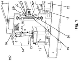
- Fig. 1 shows a welding apparatus 100 for welding foils in eg tube and / or bag form or other weldable materials, in particular of films, preferably of plastic films in tube and / or bag form and / or other weldable materials (eg internally coated aluminum and or paper composite film), hereinafter referred to as films.
- the film is present as a double plastic web, wherein the top film is to be welded to the bottom film at an open location to provide a bag or an airtight or vacuum-tight film package.
- the device can thus be readily used in a Vakuumierêt.
- the device in this case comprises an upper movable strip heater 10 with a heating element. Furthermore, the device comprises a lower heating tape carrier 11, for example with a second heating element. Alternatively, this heating element may be a processing element, such as an unheated stamping strip or a comparable element.
- a positioning unit 12 with a stepping motor 25 (FIG. Fig. 2 ), which is arranged within the unit 12, and actuates a linear drive.
- a power transmission element 13 connects the positioning unit 12 with the upper strip heater 10 via a connecting element 14.
- the power transmission element 13 is designed as an actuating pin, wherein this via a coupling part 15 at a z.
- B. T-shaped support 16 is connected by a connecting screw 17 with the connecting element 14.
- the Connecting element 14 is fastened or screwed to one side of the heating tape carrier 10.
- the double arrow R the direction of movement of the linear drive and the upper Schubandanis 10 is indicated.
- a total of two such positioning units 12 are present, to the right and left of the strip heater 10.
- the two heating units 10 associated with the two positioning units 12 are in the idle state in a zero position NP.
- Fig. 1 shows a position between the zero position and a welding position SP.
- the first movable strip carrier is moved by the drive with the positioning units 12 between an open position corresponding to the zero position and the welding position up or down.
- the upper heating tape carrier moves in the direction of the lower heating tape carrier.
- At least one sensor for monitoring the movement between the open position or zero position NP and the welding position or welding position SP is present.
- Both positions NP, SP are in the drawing on an element which is used as e.g. a bar code film is executed, which will be explained in more detail drawn.
- the existing in the figure position of the upper Schubandanys can be read off on the basis of another element, namely on the basis of a light barrier 20.
- the light barrier 20, which will be explained in more detail, and thus also the upper Schubandlittle are located between the zero position NP and the welding position SP ,
- sensors 20 are Fig. 1 ), 23, 24 ( Fig. 2 ), which are connected to a monitoring controller S and output to these sensor signals when a non-permissible operation, in particular a blockade of the movable strip heater carrier 10 is present.
- the monitoring controller S controls the stepping motor (s) 25 and is designed so that, in the event of such a fault, the movable strip heater carrier 10 automatically returns to the zero position NP.
- the monitoring controller S is connected to a control circuit 26, such as Fig. 2 shows, which controls the fixed to the heating tape carriers 10 and / or 11 heating elements or supplied with the required electrical heating energy.
- the sensors 23, 24 are pressure sensors or a pressure sensor arrangement, since a pressure measurement is carried out to determine the permissible operation should.
- the pressure sensors 23, 24 are arranged in the region of one of the ends of the lower Schubandangos 11, such as Fig. 1 shows.
- the pressure sensors 23, 24 detect the pressure of the left or right side of the Schubandanys 11.
- Each pressure sensor is designed as a force transducer with a spring body, in particular a bending beam and a strain gauge 28 (DMS).
- Each pressure sensor can also be designed for a maximum value or measuring range of eg 100 g to 1 kg or correspondingly from 1 N to 10 N.
- the pressure sensors 23, 24 detect an increase in pressure within the travel path between the zero position NP and the welding position SP, this is recognized as a blockage of the upper heating tape carrier. With the help of the pressure sensors 23, 24, it is also readily possible in the welding position SP the actual pressure, ie the contact pressure permanently to a preselected pressure setpoint.
- a program control which is possible for example by the controller S, a control signal for the stepping motor 25 is output.
- a control can be done electronically but also mechanically.
- the control can also be presettable and / or changed, for example, by means of micrometer screws.
- a second sensor 20 (FIG. Fig. 2 ) connected to the controller S.
- Fig. 1 shows as a bar code (30) scanning photocell 20 executed.
- the bar code (30) is z. B. arranged on a transparent film 19, for example, printed, and consists of different thick lines, so that a continuous detection of the position of the upper heating tape carrier 10 is possible by the light barrier.
- a monitoring of the linear travel of the positioning unit 12 is thus realized by the light barrier 20, which scans the bar code (30).
- step losses of the stepping motor 25 can be detected.
- a failure may not only be a blockade of the upper heater carrier, but also a step loss of the stepper motor 25.
- the sensors 23, 24 are also used to monitor the movement between the open position (zero position NP) and the welding position SP.
Landscapes
- Engineering & Computer Science (AREA)
- Mechanical Engineering (AREA)
- Lining Or Joining Of Plastics Or The Like (AREA)
- Package Closures (AREA)
Abstract
Description
- Die Erfindung betrifft ein Verfahren nach dem Oberbegriff des Anspruches 1 bzw. nach Anspruch 12, 13 oder 14.
- Weiterhin betrifft die Erfindung eine Vorrichtung nach Anspruch 15.
- Bei Folienschweißvorrichtungen zum Verschweißen von Folien in z.B. Schlauch- und/oder Beutelform oder anderer verschweißbarer Materialien (z.B. innenbeschichtete Alu- und/oder Papierverbundfolien) besteht das Problem, dass innerhalb des Verfahrweges eine Blockade eines verfahrbaren Heizbandträgers stattfinden kann. Bei der Verwendung von Schrittmotoren ist dies durch die Blockaden hervorgerufener Schrittverluste sehr nachteilig. Diese unzulässige Klemmung, z.B. der Folie, ist daher zu vermeiden.
- Aus der
DE 40 34 044 A1 ist ein Verfahren zur Herstellung von Kunststoffbeuteln mit einer Schweißeinrichtung bekannt, wobei ein Beutelautomat mit großer Geschwindigkeit Verwendung findet. Diese umfasst einen Servomotor sowie eine Rechnersteuerung. An Vorzugswalzen ist ein Geber angeschlossen, der Steuerimpulse abnimmt und der Rechnersteuerung zuführt. - In der
DE 42 41 974 C1 ist eine Vorrichtung zur Steuerung von Schweißwerkzeugen an Folienschweißmaschinen mit einem durch Schrittmotoren angetriebenen Schweißbalken gezeigt und beschrieben. Damit bei vergleichsweise hoher Leistung z.B. als Beutelautomat mit großen Geschwindigkeiten eine äußerst feinfühlige Einstellung des Schweißdrucks gewährleistet wird, ist ein Antriebsorgan von einem Schraubgewinde gebildet. Entsprechend einer Stromaufnahme der Motoren ist der Schweißdruck an der Kunststofffolie einstellbar. - Die
DE 103 08 345 B4 beschreibt eine Schweißvorrichtung mit zwei Heizbändern, von denen das eine als Arbeitsband und das andere als Messband dient. Eine Regelung nutzt eine Dehnung, wobei Halleffekt-Sensoren eingesetzt sind. - Weiterhin ist aus der
DE 202008017648 U1 eine Verpackungsmaschine mit Mitteln zum Verschließen eines Verpackungsbeutels, und zwar mittels Kaltversiegelung bekannt. Durch einen Drucksensor wird ein Verschließdruck erfasst. - Der Erfindung liegt die Aufgabe zugrunde, ein Verfahren und eine Vorrichtung zu schaffen, die Störungen, wie eine Blockade eines beweglichen Heizbandträgers während einer Verfahrbewegung automatisch berücksichtigt. Weiterhin soll die Erfindung eine vorwählbare Anpreßdruck- und Temperaturregelung ermöglichen sowie eine laufende Überwachung und Protokollierung des gesamten Schweißvorgangs erlauben.
- Diese Aufgabe wird durch die Merkmale der unabhängigen Ansprüche erreicht.
- Durch die Erfindung wird eine nicht zugelassene Klemmung erkannt. Nur bei nicht vorhandener Störung des beweglichen Heizbandträgers und Drucklosigkeit des unbeweglichen Heizbandträgers wird ein Positionierprozess beendet und ein Schweißvorgang ausgelöst. Dieser Schutz gewährleistet, dass keine Beschädigungen an den Heizelementen bzw. der Folie oder z.B. an einem Finger einer Bedienperson entstehen. Ebenfalls wird durch die Erfindung ermöglicht, daß die Schweißtemperatur und -dauer sowie der Anpreßdruck des beweglichen auf den unbeweglichen Heizbandträger voreinstellbar ist und im Verlauf des Schweißvorgangs überwacht, elektronisch geregelt und protokolliert wird.
- Weitere vorteilhafte Ausgestaltungen der Erfindung sind in den Unteransprüchen gekennzeichnet.
- In einer vorteilhaften Weiterbildung des erfindungsgemäßen Verfahrens ist vorgesehen, dass der nicht-zulässige Betrieb eine Blockade des beweglichen Heizbandträgers oder ein unzulässiger Druckanstieg des unbeweglichen Heizbandträgers ist. Insbesondere ist eine Blockade des beweglichen Heizbandträgers, ein unzulässiger Druckanstieg des unbeweglichen Heizbandträgers und ein zu frühes Aufheizen des/r Heizelemente/s bzw. ein Aufheizen außerhalb der Schweißposition zu vermeiden, da es sonst zu Verbrennungen führen kann.
- Vorteilhaft ist, wenn der bewegliche Heizbandträger automatisch in eine Nullposition und/oder Öffnungsstellung zurückfährt, wenn der nicht-zulässige Betrieb vorliegt. Ein Verfahren des beweglichen Heizbandträgers in die Nullposition ist bei erkannten Schrittverlusten eines Schrittmotors zweckmäßig.
- Bei einer weiteren vorteilhaften Ausführung der Erfindung erfolgt eine Feststellung des zulässigen Betriebs durch eine Anpressdruckmessung. Innerhalb des Verfahrwegs muss der unbewegliche Heizbandträger drucklos sein. Wird ein Druckanstieg festgestellt, dann deutet dies auf eine nicht zugelassene Klemmung hin, wobei der bewegliche Heizbandträger automatisch in die Nullposition zurückfährt. Für das Schweißgerät bzw. die Vorrichtung sind vorzugsweise unter dem unbeweglichen Heizbandträger angeordnete Drucksensoren vorgesehen, die den Anpressdruck feststellen, woraus über eine entsprechende Programmsteuerung ein Signal für den Schrittmotor entwickelt wird.
- Bevorzugterweise wird zur Druckmessung ein Sensor verwendet, der aus einem Wägezellenpaar besteht, wobei jeweils eine Wägezelle im Bereich eines der Enden des unbeweglichen Heizbandträgers angeordnet ist. Eine Wägezelle umfasst einen Dehnungsmessstreifen, so dass über die Dehnung des Dehnungsmessstreifens in bekannter Art und Weise die Druckmessung erfolgt. Diese Wägezellenanordnung erfasst den genauen Druck an jeder beliebigen Stelle entlang des unbeweglichen Heizbandträgers, so dass ein genauer Vergleich mit einem Sollwert möglich ist.
- In einer weiteren vorteilhaften Weiterbildung des erfindungsgemäßen Verfahrens ist vorgesehen, dass zur Feststellung des zulässigen Betriebs eine optische Messung, insbesondere zur laufenden optischen Überwachung eines Verfahrweges, erfolgt. Vorzugsweise ist der Sensor als eine einen Balkencode abtastende Lichtschranke ausgeführt. Dadurch ist eine Positionserkennung für den beweglichen Heizbandträger vorgesehen. Hierzu kann beispielsweise eine bedruckte durchsichtige Folie oder ein Lochblechstreifen angeordnet sein, die mit verschieden starken Strichen versehen sind, so dass sich durch eine entsprechende Optik immer die Position des beweglichen Heizbandträgers feststellen lässt.
- Alternativ zur dieser optischen Messung kann eine Überwachung des linearen Verfahrweges durch einen anderen Wegsensor erfolgen. Möglich wäre ebenfalls der Einsatz eines Inkrementalwertgebers, eines Absolutwertgebers, eines Potentiometers, eines mechanischen Abtastesystems beispielsweise mit Mikroschaltern oder Reedkontakten, eine Lichtintensitätsmessung, beispielsweise eine Fotozelle im sichtbaren oder unsichtbaren Spektrum, ein optisches Kamerasystem oder ein Lasersystem. Durch diese laufende Überwachung werden durch Blockaden hervorgerufene Schrittverluste des Schrittmotors sofort erkannt. Bei erkannten Schrittverlusten verfährt die Positioniereinheit den beweglichen Heizbandträger automatisch in die Nullposition.
- Erst wenn der bewegliche Heizbandträger die Zielposition erreicht hat und dabei kein Schrittverlust und kein unerlaubter Druckanstieg am unbeweglichen Heizbandträger festgestellt wurde, ist der Positionierprozess beendet. Die Positioniereinheiten stellen dann den Solldruck zwischen unbeweglichem und beweglichem Heizbandträger ein. Zur Druckregelung während des Schweißvorgangs kann der Drucksensor bzw. das Wägezellenpaar eingesetzt werden.
- Als sehr günstig hat sich für derartige Schweißgeräte ein Antrieb der Positioniereinheit herausgestellt, der einen Schrittmotor aufweist. Möglich wären ebenfalls Hydraulikantriebe, Pneumatikantriebe, Elektro- oder Linearmotoren, wie Gleichstrom- oder Wechselstrommotoren mit Bürsten oder bürstenlose Motoren.
- In einer anderen bevorzugten Ausführung des erfindungsgemäßen Verfahrens erfolgt während der eigentlichen Schweißzyklen eine permanente Ausregelung des vorgewählten Anpreßdrucks über die Steuerung durch die Drucksensoren mittels der Positioniereinheit. Durch diese Druckregelung wird eine gleichbleibende Qualität der Schweißverbindung erreicht.
- Bei einer erfindungsgemäßen Gestaltung des Verfahrens zum Betreiben einer Schweißvorrichtung zum Verschweißen von verschweißbaren Materialien, insbesondere von Folien, vorzugsweise von Kunststoff-Folien in Schlauch-und/oder -Beutelform und/oder anderer schweißbarer Materialien (z.B. innenbeschichtete Alu- und/oder Papierverbundfolie), mit einem ersten beweglichen Heizbandträger, der ein Heizelement trägt und insbesondere mit einem zweiten Heizbandträger, an dem ein Element, insbesondere ein zweites Heizelement oder ein unbeheiztes Element angeordnet ist, wobei der erste bewegliche Heizbandträger durch einen Antrieb mindestens einer Positioniereinheit zwischen einer Öffnungsstellung und einer Schweißstellung verfahrbar ausgeführt ist, ist vorgesehen, dass der bewegliche Heizbandträger verfahren wird, bis ein vorgewählter Anpreßdruck erreicht wird, daß nach Erreichen des vorgewählten Anpreßdrucks die Impulssteuerung eingeschaltet wird und eingeschaltet bleibt bis eine vorgewählte Temperatur erreicht ist, dass nach Erreichen der vorgewählten Temperatur die vorgewählte Schweißzeit beginnt und die Verschweißung erfolgt und die Impulssteuerung eingeschaltet bleibt bis zum Ablauf der vorgewählten Schweißzeit, daß nach Ablauf der vorgewählten Schweißzeit die Impulssteuerung abschaltet und die vorgewählte Kühlzeit beginnt, wobei ein vorgewählter Anpreßdruck aufrechterhalten wird, und dann nach Ablauf der vorgewählten Kühlzeit der bewegliche Heizbandträger in die Öffnungsstellung zurückfährt.
- Ein weiterer Haupterfindungsgedanke besteht darin, ein Verfahren zum Betreiben eines wärmeimpulsgesteuerten und/oder dauerbeheizten Folienschweiß- und/oder Heißsiegelgerätes mit vorwählbarer elektronischer, prozessorgesteuerter Anpreßdruck- und Temperaturregelung zu schaffen, bei dem eine Druckmessung, Drucküberwachung und/oder eine Druckregelung durch Drucksensoren erfolgt. Das Verfahren kann leicht durch eine Software der Steuerung umgesetzt werden.
- Ein anderer Grundgedanke besteht darin, ein Verfahren zum Betreiben eines wärmeimpulsgesteuerten und/oder dauerbeheizten Folienschweiß-und/oder Heißsiegelgerätes zu schaffen, bei dem das Schweiß- und/oder Heißsiegelgerät bei einem Fehler, insbesondere bei einem Fehler während einer Bewegung eines Heizbandträgers zwischen der Öffnungsstellung und der Schweißstellung, einen neuen Schweißvorgang erst startet, wenn ein Bestätigungssignal von einer Bedienperson bzw. einem Anwender ausgelöst wird. Nichtverschlossene Beutel und dergleichen bleiben daher keinesfalls unerkannt oder unbemerkt.
- Ein weiterer Grundgedanke liegt darin, ein Verfahren zum Betreiben eines wärmeimpulsgesteuerten und/oder dauerbeheizten Folienschweiß-und/oder Heißsiegelgerätes zu schaffen, bei dem Daten, insbesondere Fehler-, Schweißprozess-, und/oder andere Parameterdaten, auf einem Speichermedium abgespeichert und/oder über eine Schnittstelle, insbesondere über eine USB-Schnittstelle, vorzugsweise durch einen USB-Stick, ausgelesen werden. Die Daten können durch z.B. einen USB-Stick gespeichert und zu Qualitätssicherungs-Zwecken aufbewahrt werden.
- Ein Ausführungsbeispiel wird anhand der Zeichnungen näher erläutert, wobei weitere vorteilhafte Weiterbildungen der Erfindung und Vorteile derselben beschrieben sind. Es zeigen in rein schematischer Darstellung:
-
Fig. 1 eine perspektivische Darstellung einer Schweißvorrichtung, und -
Fig. 2 ein Blockschaltbild der Steuerung der Schweißvorrichtung. -
Fig. 1 zeigt eine Schweißvorrichtung 100 zum Verschweißen von Folien in z.B. Schlauch- und/oder Beutelform oder anderer verschweißbarer Materialien, insbesondere von Folien, vorzugsweise von Kunststoff-Folien in Schlauch-und/oder -Beutelform und/oder anderer schweißbarer Materialien (z.B. innenbeschichtete Alu- und/oder Papierverbundfolie), nachfolgend als Folien bezeichnet. Die Folie liegt z.B. als eine doppelte Kunststoffbahn vor, wobei die obere Folie mit der unteren Folie an einer offenen Stelle verschweißt werden soll, um einen Beutel oder eine luftdichte oder vakuumdichte Folienverpackung zu schaffen. Die Vorrichtung kann also ohne Weiteres in einem Vakuumiergerät eingesetzt werden. - Wie die
Figur 1 veranschaulicht, umfasst die Vorrichtung in diesem Fall einen oberen beweglichen Heizbandträger 10 mit einem Heizelement. Weiterhin umfasst die Vorrichtung einen unteren Heizbandträger 11 z.B mit einem zweiten Heizelement. Alternativ kann dieses Heizelement ein Verarbeitungselement, wie z.B. eine unbeheizte Prägeleiste oder ein vergleichbares Element sein. - Zu sehen ist außerdem in
Fig. 1 eine Positioniereinheit 12 mit einem Schrittmotor 25 (Fig. 2 ), der innerhalb der Einheit 12 angeordnet ist, und einen Linearantrieb betätigt. Ein Kraftübertragungselement 13 verbindet die Positioniereinheit 12 mit dem oberen Heizbandträger 10 über ein Verbindungselement 14. Das Kraftübertragungselement 13 ist als Betätigungsstift ausgeführt, wobei dieses über ein Kupplungsteil 15 an einem z. B. T-förmigen Träger 16 durch eine Verbindungsschraube 17 mit dem Verbindungselement 14 verbunden ist. Das Verbindungselement 14 ist an einer Seite des Heizbandträgers 10 befestigt bzw. verschraubt. Durch den Doppelpfeil R ist die Bewegungsrichtung des Linearantriebs und des oberen Heizbandträgers 10 angedeutet. Insgesamt sind zwei derartige Positioniereinheiten 12 vorhanden, und zwar rechts und links vom Heizbandträger 10. Die dem oberen Heizbandträger 10 zugeordneten zwei Positioniereinheiten 12 befinden sich im Ruhezustand in einer Nullposition NP.Fig. 1 zeigt eine Stellung zwischen der Nullposition und einer Schweißposition SP. - Der erste bewegliche Heizbandträger wird durch den Antrieb mit den Positioniereinheiten 12 zwischen einer Öffnungsstellung, die der Nullposition entspricht, und der Schweißstellung nach oben oder unten verfahren. Wenn ein Schweißprozess gestartet wird, fährt der obere Heizbandträger in Richtung des unteren Heizbandträgers.
- Erfindungsgemäß ist zumindest ein Sensor zur Überwachung der Bewegung zwischen der Öffnungsstellung bzw. Nullposition NP und der Schweißstellung bzw. Schweißposition SP vorhanden. Beide Positionen NP, SP sind in der Zeichnung an einem Element, das als z.B. eine Balkencodefolie ausgeführt ist, die noch näher erläutert wird, eingezeichnet. Die in der Figur vorhandene Position des oberen Heizbandträgers lässt sich anhand eines anderes Elementes ablesen, und zwar anhand einer Lichtschranke 20. Die Lichtschranke 20, die noch näher erläutert wird, und somit auch der obere Heizbandträger befinden sich zwischen der Nullposition NP und der Schweißposition SP.
- Vorzugsweise sind Sensoren 20 (
Fig. 1 ), 23, 24 (Fig. 2 ) vorhanden, die mit einer Überwachungssteuerung S verbunden sind und an diese Sensorsignale ausgeben, wenn ein nicht-zulässiger Betrieb, insbesondere eine Blockade des beweglichen Heizbandträgers 10 vorliegt. Die Überwachungssteuerung S steuert den bzw. die Schrittmotoren 25 und ist so ausgeführt, dass im Falle einer solchen Störung der bewegliche Heizbandträger 10 automatisch in die Nullposition NP zurückfährt. Außerdem ist die Überwachungssteuerung S mit einem Steuerkreis 26 verbunden, wieFig. 2 zeigt, der die an den Heizbandträgern 10 und/oder 11 befestigten Heizelemente ansteuert bzw. mit der erforderlichen elektrischen Heizenergie versorgt. - Die Sensoren 23, 24 sind Drucksensoren bzw. eine Drucksensoranordnung, da zur Feststellung des zulässigen Betriebs eine Druckmessung erfolgen soll. Die Drucksensoren 23, 24 sind im Bereich eines der Enden des unteren Heizbandträgers 11 angeordnet, wie
Fig. 1 zeigt. Die Drucksensoren 23, 24 erfassen den Druck der linken bzw. rechten Seite des Heizbandträgers 11. Jeder Drucksensor ist als Kraftaufnehmer mit einem Federkörper, insbesondere einem Biegebalken und einem Dehnungsmeßstreifen 28 (DMS) ausgeführt. Jeder Drucksensor kann außerdem für einen Maximalwert oder Messbereich von z.B. 100 g bis 1 kg oder entsprechend von 1 N bis 10 N ausgeführt sein. Erfassen die Drucksensoren 23, 24 einen Druckanstieg innerhalb des Verfahrweges zwischen der Nullposition NP und der Schweißposition SP, wird dies als Blockade des oberen Heizbandträgers erkannt. Mit Hilfe der Drucksensoren 23, 24 ist es auch ohne weiteres möglich, in der Schweißstellung SP den Ist-Druck, d.h. den Anpressdruck permanent auf einen vorgewählten Druck-Sollwert auszuregeln. Durch eine Programmsteuerung, die z.B. durch die Steuerung S möglich ist, wird ein Steuersignal für den Schrittmotor 25 ausgegeben. - Durch die Drucksensoren 23, 24 ist es auch möglich, unabhängig von der Überwachung der Bewegung zwischen der Öffnungsstellung bzw. Nullposition NP und der Schweißstellung bzw. Schweißposition SP einen für die Verschweißung erforderlichen Anpressdruck zu messen, zu überwachen und/oder zu regeln bzw. nachzuregeln. Eine Regelung kann elektronisch aber auch mechanisch erfolgen. Die Regelung kann beispielsweise auch über Mikrometerschrauben voreinstellbar und/oder veränderbar sein.
- Zur Feststellung des zulässigen Betriebs erfolgt zusätzlich eine optische Messung, und zwar eine laufende optische Überwachung des Verfahrweges. Hierzu ist ein zweiter Sensor 20 (
Fig. 2 ) mit der Steuerung S verbunden. Dieser ist, wieFig. 1 zeigt, als eine einen Balkencode (30) abtastende Lichtschranke 20 ausgeführt. Der Balkencode (30) ist z. B. auf einer durchsichtigen Folie 19 angeordnet, z.B. aufgedruckt, und besteht aus unterschiedlich dicken Strichen, so dass durch die Lichtschranke eine laufende Erfassung der Position des oberen Heizbandträgers 10 möglich ist. Eine Überwachung des linearen Verfahrweges der Positioniereinheit 12 wird also durch die Lichtschranke 20, die den Balkencode (30) abtastet, realisiert. Dadurch können Schrittverluste des Schrittmotors 25 erkannt werden. Ein Fehler kann nicht nur eine Blockade des oberen Heizbandträgers, sondern auch ein Schrittverlust des Schrittmotors 25 sein. - Wenn ein Schweißprozess gestartet wird, fährt der obere Heizbandträger 10 in Richtung des unteren Heizbandträgers 11. Erst wenn der obere Heizbandträger seine Zielposition störungsfrei erreicht hat und das untere Heizband drucklos ist, startet der Schweißvorgang und die Heizbänder werden für die Dauer einer eingestellten Schweißzeit auf eine vorgewählte Temperatur und Schweißdauer ausgeregelt. Ist der Schweißvorgang abgelaufen, verfährt der obere Heizbandträger in die Nullposition NP zurück.
- Die Sensoren 23, 24 dienen auch zur Überwachung der Bewegung zwischen der Öffnungsstellung (Nullposition NP) und der Schweißstellung SP.
-
- 100
- Schweißvorrichtung
- 10
- Erster Heizbandträger
- 11
- Zweiter Heizbandträger
- 12
- Positioniereinheit
- 13
- Kraftübertragungselement
- 14
- Verbindungselement
- 15
- Kupplungsteil
- 16
- Träger
- 17
- Verbindungsschraube
- 19
- Folie
- 20
- Lichtschranke
- 21
- -
- 22
- -
- 23, 24
- Sensoren
- 25
- Schrittmotor
- 26
- Steuerkreis
- 27
- -
- 28
- Dehnungsmeßstreifen
- 30
- Balkencode
- NP
- Nullposition
- SP
- Schweißposition
- S
- Überwachungssteuerung
- DMS
- Dehnungsmessstreifen
Claims (21)
- Verfahren zum Betreiben einer Schweißvorrichtung (100) zum Verschweißen von verschweißbaren Materialien, insbesondere von Folien, vorzugsweise von Kunststoff-Folien in Schlauch- und/oder -Beutelform und/oder anderer schweißbarer Materialien (z. B. innenbeschichtete Alu- und/oder Papierverbundfolie), mit einem ersten beweglichen Heizbandträger (10), der ein Heizelement trägt und insbesondere mit einem zweiten, unbeweglichen Heizbandträger (11), an dem ein Element, insbesondere ein zweites Heizelement oder ein unbeheiztes Element angeordnet ist, wobei der erste bewegliche Heizbandträger (10) durch einen Antrieb mindestens einer Positioniereinheit (12) zwischen einer Öffnungsstellung und einer Schweißstellung verfahrbar ausgeführt ist und der Antrieb der Positioniereinheit über mindestens einen Schrittmotor und/oder einen Hydraulikantrieb und/oder Elektro- und/oder Linearmotoren, wie Gleichstrom- oder Wechselstrommotoren mit Bürsten oder bürstenlose Motoren erfolgt, dadurch gekennzeichnet, dass zumindest ein Sensor (23, 24; 20) zur Überwachung der Bewegung zwischen der Öffnungsstellung und der Schweißstellung vorhanden ist, der mit einer Überwachungssteuerung (S) verbunden ist und an diese ein oder mehrere Signale ausgibt, wenn ein nicht-zulässiger Betrieb vorliegt.
- Verfahren nach Anspruch 1, dadurch gekennzeichnet, dass der nicht-zulässige Betrieb eine Blockade des beweglichen Heizbandträgers (10) ist.
- Verfahren nach Anspruch 1 oder 2, dadurch gekennzeichnet, dass der bewegliche Heizbandträger (10) automatisch in eine Nullposition (NP) und/oder in die Öffnungsstellung zurückfährt, wenn der nicht-zulässige Betrieb vorliegt.
- Verfahren nach einem der vorhergehenden Ansprüche, dadurch gekennzeichnet, dass zur Feststellung des zulässigen Betriebs eine Anpreßdruckmessung erfolgt.
- Verfahren nach einem der vorhergehenden Ansprüche, dadurch gekennzeichnet, dass zur Feststellung des zulässigen Betriebs eine optische Messung, insbesondere zur laufenden optischen Überwachung eines Verfahrweges erfolgt.
- Verfahren nach einem der vorhergehenden Ansprüche, dadurch gekennzeichnet, dass zur Feststellung des zulässigen Betriebs ein Inkrementalwertgeber, ein Absolutwertgeber, ein Potentiometer, ein mechanisches Abtastesystem, beispielsweise mit Mikroschaltern oder Reedkontakten, eine Lichtintensitätsmessung, beispielsweise eine Fotozelle im sichtbaren oder unsichtbaren Spektrum, ein optisches Kamerasystem und/oder ein Lasersystem zur Erfassung von Verfahrweginformationen, insbesondere durch Abtastung eines Lochblechs, Balkendiagramms, Barcodes oder dergleichen, eingesetzt wird.
- Verfahren nach einem der vorhergehenden Ansprüche, dadurch gekennzeichnet, daß während mindestens eines Schweißzyklus eine permanente Ausregelung eines vorgewählten Anpreßdrucks über eine Steuerung (S) durch Drucksensoren (23, 24), mittels der Positioniereinheit (12) erfolgt, wobei jeder Drucksensor (23, 24) insbesondere eine Wägezelle oder ein Dehnungsmeßstreifen ist.
- Verfahren, insbesondere nach einem der vorhergehenden Ansprüche, dadurch gekennzeichnet, daß der bewegliche Heizbandträger (10) verfahren wird, bis ein vorgewählter Anpreßdruck erreicht wird.
- Verfahren nach Anspruch 8, dadurch gekennzeichnet, daß nach Erreichen des vorgewählten Anpreßdrucks die Impulssteuerung eingeschaltet wird und eingeschaltet bleibt bis eine vorgewählte Temperatur erreicht ist.
- Verfahren nach Anspruch 9, dadurch gekennzeichnet, daß nach Erreichen der vorgewählten Temperatur die vorgewählte Schweißzeit beginnt und die Verschweißung erfolgt und die Impulssteuerung eingeschaltet bleibt bis zum Ablauf der vorgewählten Schweißzeit.
- Verfahren nach Anspruch 10, dadurch gekennzeichnet, daß nach Ablauf der vorgewählten Schweißzeit die Impulssteuerung abschaltet und die vorgewählte Kühlzeit beginnt, wobei ein vorgewählter Anpreßdruck aufrechterhalten wird, und dann nach Ablauf der vorgewählten Kühlzeit der bewegliche Heizbandträger (10) in die Öffnungsstellung zurückfährt.
- Verfahren zum Betreiben eines wärmeimpulsgesteuerten und/oder dauerbeheizten Folienschweiß- und/oder Heißsiegelgerätes mit vorwählbarer elektronischer, prozessorgesteuerter Anpreßdruck- und Temperaturregelung, bei dem eine Druckmessung, Drucküberwachung und/oder eine Druckregelung durch Drucksensoren erfolgt, insbesondere unter Verwendung eines Verfahrens nach einem der vorhergehenden Ansprüche.
- Verfahren zum Betreiben eines wärmeimpulsgesteuerten und/oder dauerbeheizten Folienschweiß- und/oder Heißsiegelgerätes, insbesondere unter Verwendung eines Verfahrens nach einem der vorhergehenden Ansprüche, bei dem Daten, insbesondere Fehler-, Schweißprozess-, und/oder andere Parameterdaten, auf einem Speichermedium abgespeichert und/oder über eine Schnittstelle, insbesondere über eine USB-Schnittstelle, vorzugsweise durch einen USB-Stick, ausgelesen werden.
- Verfahren zum Betreiben eines wärmeimpulsgesteuerten und/oder dauerbeheizten Folienschweiß- und/oder Heißsiegelgerätes, insbesondere unter Verwendung eines Verfahrens nach einem der vorhergehenden Ansprüche, bei dem das Schweißgerät bei einem Fehler, insbesondere bei einem Fehler während einer Bewegung eines Heizbandträgers (10) zwischen der Öffnungsstellung und der Schweißstellung, einen neuen Schweißvorgang erst startet, wenn ein Bestätigungssignal von einer Bedienperson bzw. einem Anwender ausgelöst wird.
- Vorrichtung zur Durchführung des Verfahrens nach einem der vorhergehenden Ansprüche, gekennzeichnet durch mindestens einen Sensor (20, 23 und 24) zur Überwachung der Bewegung des Heizbandträgers (10) zwischen der Öffnungsstellung und der Schweißstellung und durch die Überwachungssteuerung (S).
- Vorrichtung nach Anspruch 15, dadurch gekennzeichnet, dass zur Feststellung des zulässigen Betriebs ein Inkrementalwertgeber, ein Absolutwertgeber, ein Potentiometer, ein mechanisches Abtastesystem, beispielsweise mit Mikroschaltern oder Reedkontakten, eine Lichtintensitätsmessung, beispielsweise eine Fotozelle im sichtbaren oder unsichtbaren Spektrum, ein optisches Kamerasystem und/oder ein Lasersystem zur Erfassung von Verfahrweginformationen, insbesondere durch Abtastung eines Lochblechs, Balkendiagramms, Barcodes oder dergleichen, vorgesehen ist.
- Vorrichtung nach Anspruch 15 oder 16, dadurch gekennzeichnet, dass ein Sensor (23, 24) vorhanden ist, wobei jeweils mindestens eine Wägezelle oder jeweils mindestens ein Dehnungsmeßstreifen (28) im Bereich eines der Enden des unbeweglichen Heizbandträgers (11) angeordnet ist.
- Vorrichtung nach einem der Ansprüche 15 bis 17, dadurch gekennzeichnet, dass ein Sensor (20) als ein Wegsensor ausgeführt ist.
- Vorrichtung nach einem der Ansprüche 15 bis 18, dadurch gekennzeichnet, dass der Sensor (20) als eine einen Balkencode (30) abtastende Lichtschranke (20) ausgeführt ist.
- Vorrichtung nach einem der Ansprüche 15 bis 19, dadurch gekennzeichnet, dass der Antrieb der Positioniereinheit (12) einen Schrittmotor (25) aufweist.
- Vorrichtung nach einem der Ansprüche 15 bis 20, dadurch gekennzeichnet, daß der Antrieb der Positioniereinheit (12) über einen Hydraulikantrieb, einen Pneumatikantrieb, Elektro- und/oder Linearmotoren, wie Gleichstrom- oder Wechselstrommotoren mit Bürsten oder bürstenlose Motoren erfolgt.
Applications Claiming Priority (1)
| Application Number | Priority Date | Filing Date | Title |
|---|---|---|---|
| DE102011001167.6A DE102011001167B4 (de) | 2011-03-09 | 2011-03-09 | Verfahren zum Betreiben einer Schweißvorrichtung, insbesondere eines wärmeimpulsgesteuerten und/oder dauerbeheizten Folienschweiß- und/oder Heißsiegelgerätes mit vorwählbarer elektronischer, prozessorgesteuerter Anpressdruck- und Temperaturregelung und Vorrichtung hierzu |
Publications (3)
| Publication Number | Publication Date |
|---|---|
| EP2497621A2 true EP2497621A2 (de) | 2012-09-12 |
| EP2497621A3 EP2497621A3 (de) | 2013-08-28 |
| EP2497621B1 EP2497621B1 (de) | 2018-12-19 |
Family
ID=45841208
Family Applications (1)
| Application Number | Title | Priority Date | Filing Date |
|---|---|---|---|
| EP12157689.6A Active EP2497621B1 (de) | 2011-03-09 | 2012-03-01 | Verfahren zum Betreiben einer Schweißvorrichtung, insbesondere eines wärmeimpulsgesteuerten und/oder dauerbeheizten Folienschweiß- und/oder Heißsiegelgerätes mit vorwählbarer elektronischer, prozessorgesteuerter Anpreßdruck- und Temperaturregelung und Vorrichtung hierzu |
Country Status (2)
| Country | Link |
|---|---|
| EP (1) | EP2497621B1 (de) |
| DE (1) | DE102011001167B4 (de) |
Cited By (5)
| Publication number | Priority date | Publication date | Assignee | Title |
|---|---|---|---|---|
| CN103811818A (zh) * | 2014-02-20 | 2014-05-21 | 东莞市德瑞精密设备有限公司 | 铝塑膜封印调整装置 |
| EP2942183A1 (de) | 2014-05-07 | 2015-11-11 | Rische + Herfurth GmbH | Kalibrationsset für eine schweissvorrichtung, insbesondere ein folienschweiss- und/oder heisssiegelgerät, und kalibrierverfahren für eine schweissvorrichtung |
| CN112025131A (zh) * | 2020-09-30 | 2020-12-04 | 宁波恒帅股份有限公司 | 一种歧管焊接机 |
| CN114334743A (zh) * | 2022-01-06 | 2022-04-12 | 广东技术师范大学 | 一种基于芯片封装用预压装置 |
| CN114567974A (zh) * | 2022-03-24 | 2022-05-31 | 欧普照明股份有限公司 | 电路板生产工艺及生产系统、灯带生产系统及灯带 |
Families Citing this family (1)
| Publication number | Priority date | Publication date | Assignee | Title |
|---|---|---|---|---|
| DE102018113207A1 (de) * | 2018-06-04 | 2019-12-05 | Rovema Gmbh | Schlauchbeutelmaschine mit Körperteilüberwachung |
Citations (4)
| Publication number | Priority date | Publication date | Assignee | Title |
|---|---|---|---|---|
| DE4034044A1 (de) | 1989-10-31 | 1991-05-02 | Lehmacher & Sohn Masch | Verfahren zur herstellung von kunststoffbeuteln mit hilfe eines kunststoffbeutel-automaten |
| DE4241974C1 (de) | 1992-12-12 | 1993-11-25 | Lemo Maschb Gmbh | Vorrichtung zur Steuerung von Schweißwerkzeugen an Folienschweißmaschinen, insbesondere bei der Herstellung von Beuteln, Säcken oder dgl. aus thermoplastischen Kunststoffolienbahnen |
| DE10308345A1 (de) | 2003-02-27 | 2004-09-16 | Toss Gmbh & Co. Kg Verpackungssysteme | Verfahren zur Begrenzung der maximalen Temperatur eines Heizbandes und Schweißschiene zur Durchführung dieses Verfahrens |
| DE202008017648U1 (de) | 2008-08-04 | 2010-04-22 | hawo Gerätebau GmbH & Co Maschinenbau KG | Verpackungsmaschine |
Family Cites Families (14)
| Publication number | Priority date | Publication date | Assignee | Title |
|---|---|---|---|---|
| US2719567A (en) * | 1949-11-16 | 1955-10-04 | Emhart Mfg Co | Apparatus for heat sealing |
| DE2520475A1 (de) * | 1975-05-07 | 1976-11-25 | Beck & Co Packautomaten | Schutzvorrichtung fuer einen schweissbacken |
| CH652675A5 (de) * | 1981-10-22 | 1985-11-29 | De La Rue Giori Sa | Vorrichtung zur automatischen verarbeitung von stapeln druckfrischer wertscheinbogen, insbesondere banknotenbogen, zu buendelpaketen. |
| US4553373A (en) * | 1982-09-14 | 1985-11-19 | Fmc Corporation | Method and apparatus for packaging articles such as fruit |
| US4650535A (en) * | 1985-08-13 | 1987-03-17 | Creative Packaging Machinery, Inc. | Apparatus for heat-sealing thermoplastic sheeting |
| IT1203342B (it) * | 1987-02-23 | 1989-02-15 | A W A X Srl | Procedimento ed apparecchio per impacchettare automaticamente articoli diversi in sacchetti di plastica a misura di cliente fabbricati sul posto in una cassa di supermercato |
| US4768327A (en) * | 1987-06-22 | 1988-09-06 | Package Machinery Company | Packaging machine with variable sealing jaw displacement apparatus |
| US5321230A (en) * | 1993-06-02 | 1994-06-14 | Shanklin Corporation | Seal wire heat control system |
| JP3473861B2 (ja) * | 1993-12-28 | 2003-12-08 | 株式会社イシダ | 包材の封止部に介在する介在物の有無の判定方法 |
| ES2209098T3 (es) * | 1998-04-15 | 2004-06-16 | TETRA LAVAL HOLDINGS & FINANCE SA | Metodo para comprobar el sellado transversal en una unidad de envasar, para formar continuamente envases sellados que contienen productos alimenticios vertibles, y unidad de envasar. |
| DE20111126U1 (de) * | 2001-07-10 | 2001-10-18 | Wolf, Hans, 74821 Mosbach | Siegelnaht-Prüfgerät |
| US8695311B2 (en) * | 2006-04-26 | 2014-04-15 | Free-Flow Packaging International, Inc. | Apparatus for inflating and sealing packing cushions employing film recognition controller |
| CA2760363C (en) * | 2009-05-04 | 2015-10-20 | The United States Of America, As Represented By The Secretary, Department Of Health And Human Services | Selective access to cryopreserved samples |
| DE102011110620B3 (de) * | 2011-08-16 | 2013-01-17 | DüRR DENTAL AG | Verfahren zum Erzeugen von Sterilprodukten |
-
2011
- 2011-03-09 DE DE102011001167.6A patent/DE102011001167B4/de active Active
-
2012
- 2012-03-01 EP EP12157689.6A patent/EP2497621B1/de active Active
Patent Citations (4)
| Publication number | Priority date | Publication date | Assignee | Title |
|---|---|---|---|---|
| DE4034044A1 (de) | 1989-10-31 | 1991-05-02 | Lehmacher & Sohn Masch | Verfahren zur herstellung von kunststoffbeuteln mit hilfe eines kunststoffbeutel-automaten |
| DE4241974C1 (de) | 1992-12-12 | 1993-11-25 | Lemo Maschb Gmbh | Vorrichtung zur Steuerung von Schweißwerkzeugen an Folienschweißmaschinen, insbesondere bei der Herstellung von Beuteln, Säcken oder dgl. aus thermoplastischen Kunststoffolienbahnen |
| DE10308345A1 (de) | 2003-02-27 | 2004-09-16 | Toss Gmbh & Co. Kg Verpackungssysteme | Verfahren zur Begrenzung der maximalen Temperatur eines Heizbandes und Schweißschiene zur Durchführung dieses Verfahrens |
| DE202008017648U1 (de) | 2008-08-04 | 2010-04-22 | hawo Gerätebau GmbH & Co Maschinenbau KG | Verpackungsmaschine |
Cited By (10)
| Publication number | Priority date | Publication date | Assignee | Title |
|---|---|---|---|---|
| CN103811818A (zh) * | 2014-02-20 | 2014-05-21 | 东莞市德瑞精密设备有限公司 | 铝塑膜封印调整装置 |
| CN103811818B (zh) * | 2014-02-20 | 2016-03-09 | 东莞市德瑞精密设备有限公司 | 铝塑膜封印调整装置 |
| EP2942183A1 (de) | 2014-05-07 | 2015-11-11 | Rische + Herfurth GmbH | Kalibrationsset für eine schweissvorrichtung, insbesondere ein folienschweiss- und/oder heisssiegelgerät, und kalibrierverfahren für eine schweissvorrichtung |
| DE102014006566A1 (de) | 2014-05-07 | 2015-11-12 | Rische + Herfurth GmbH | Kalibrationsset für eine Schweißvorrichtung, insbesondere ein Folienschweiß- und/oder Heißsiegelgerät, und Kalibrierverfahren für eine Schweißvorrichtung |
| EP3461619A1 (de) * | 2014-05-07 | 2019-04-03 | Rische + Herfurth GmbH | Kalibrationsset für eine schweissvorrichtung, insbesondere ein folienschweiss- und/oder heisssiegelgerät, und kalibrierverfahren für eine schweissvorrichtung |
| EP3466653A1 (de) * | 2014-05-07 | 2019-04-10 | Rische + Herfurth GmbH | Kalibrationsset für eine schweissvorrichtung, insbesondere ein folienschweiss- und/oder heisssiegelgerät, und kalibrierverfahren für eine schweissvorrichtung |
| DE102014006566B4 (de) * | 2014-05-07 | 2021-06-17 | Rische + Herfurth GmbH | Kalibrationsset für eine Schweißvorrichtung, insbesondere ein Folienschweiß- und/oder Heißsiegelgerät, und Kalibrierverfahren für eine Schweißvorrichtung |
| CN112025131A (zh) * | 2020-09-30 | 2020-12-04 | 宁波恒帅股份有限公司 | 一种歧管焊接机 |
| CN114334743A (zh) * | 2022-01-06 | 2022-04-12 | 广东技术师范大学 | 一种基于芯片封装用预压装置 |
| CN114567974A (zh) * | 2022-03-24 | 2022-05-31 | 欧普照明股份有限公司 | 电路板生产工艺及生产系统、灯带生产系统及灯带 |
Also Published As
| Publication number | Publication date |
|---|---|
| EP2497621A3 (de) | 2013-08-28 |
| EP2497621B1 (de) | 2018-12-19 |
| DE102011001167B4 (de) | 2017-11-02 |
| DE102011001167A1 (de) | 2012-09-13 |
Similar Documents
| Publication | Publication Date | Title |
|---|---|---|
| EP2497621B1 (de) | Verfahren zum Betreiben einer Schweißvorrichtung, insbesondere eines wärmeimpulsgesteuerten und/oder dauerbeheizten Folienschweiß- und/oder Heißsiegelgerätes mit vorwählbarer elektronischer, prozessorgesteuerter Anpreßdruck- und Temperaturregelung und Vorrichtung hierzu | |
| EP2416941B1 (de) | Vorrichtung und verfahren zum bearbeiten eines packstoffs mittels ultraschall | |
| EP1409190B1 (de) | Widerstandsschweisseinrichtung und steuerverfahren | |
| EP0406223B1 (de) | Vorrichtung zum Verschweissen von Kunststoffbahnen | |
| AT510949B1 (de) | Steuer- und regelvorrichtung für eine biegepresse | |
| DE3045951C2 (de) | Einrichtung zum Führen einer Materialbahn | |
| DE102016107398B4 (de) | Qualitätskontrollsystem für punktschweissen | |
| DE102011075424B4 (de) | Verfahren zum Betreiben einer Quernahtsiegeleinrichtung in einer Schlauchbeutelmaschine und Quernahtsiegeleinrichtung in einer Schlauchbeutelmaschine | |
| DE69822042T2 (de) | Verfahren und Vorrichtung zum Siegeln einer Bahn, und zum Herstellen eines Verpackungsbehälters | |
| DE19950534A1 (de) | Spritzgießmaschine | |
| DE69101182T2 (de) | Verpackungsmaschine zum Heissverschweissen von Kunststoffolie mit variabler Geschwindigkeit. | |
| WO1994019142A1 (de) | Verfahren und vorrichtung zum laserschweissen | |
| EP1600412B1 (de) | Folienspleissstation | |
| EP0547322A1 (de) | Verfahren zur Überwachung der Schweissqualität beim Quetschnahtschweissen | |
| EP0240827A1 (de) | Vorrichtung zur Herstellung von Luftpolster-Versandtaschen | |
| EP3251817B1 (de) | Trennschweisseinrichtung und verfahren zum bereichsweisen fügen und bereichsweisen trennen von verschweissbaren folienbahnen mit einer trennschweisseinrichtung | |
| DE3910099C2 (de) | ||
| EP1136234B1 (de) | Verfahren und Vorrichtung zum Verschweissen von Kunststoffprofilstäben | |
| DE10144731A1 (de) | Schweißzange sowie Verfahren zur Beurteilung der Qualität einer Schweißverbindung | |
| EP3630460B9 (de) | Verfahren zur funktionsüberwachung einer schlauchbeutelmaschine | |
| EP1193579A2 (de) | Steuersystem und Verfahren zur Steuerung einer Schliesseinrichtung | |
| DE102006054100B4 (de) | Verfahren und Messerfaltmaschine zum Herstellen von Stehfalten unter variablem Gegendruck | |
| EP0329814B1 (de) | Vorrichtung zum Längsfalzen einer Bahn | |
| EP2030761A2 (de) | Vorrichtung zum automatischen Aneinanderfügen von Kunststoffbahnen | |
| WO1996000881A1 (de) | Verfahren und messanordnung zum messen der schweissnahtgeometrie |
Legal Events
| Date | Code | Title | Description |
|---|---|---|---|
| PUAI | Public reference made under article 153(3) epc to a published international application that has entered the european phase |
Free format text: ORIGINAL CODE: 0009012 |
|
| AK | Designated contracting states |
Kind code of ref document: A2 Designated state(s): AL AT BE BG CH CY CZ DE DK EE ES FI FR GB GR HR HU IE IS IT LI LT LU LV MC MK MT NL NO PL PT RO RS SE SI SK SM TR |
|
| AX | Request for extension of the european patent |
Extension state: BA ME |
|
| RIC1 | Information provided on ipc code assigned before grant |
Ipc: B29C 65/22 20060101AFI20130425BHEP Ipc: F16P 3/12 20060101ALN20130425BHEP Ipc: B29C 65/18 20060101ALN20130425BHEP Ipc: B65B 57/08 20060101ALN20130425BHEP Ipc: B29C 65/38 20060101ALN20130425BHEP |
|
| PUAL | Search report despatched |
Free format text: ORIGINAL CODE: 0009013 |
|
| AK | Designated contracting states |
Kind code of ref document: A3 Designated state(s): AL AT BE BG CH CY CZ DE DK EE ES FI FR GB GR HR HU IE IS IT LI LT LU LV MC MK MT NL NO PL PT RO RS SE SI SK SM TR |
|
| AX | Request for extension of the european patent |
Extension state: BA ME |
|
| RIC1 | Information provided on ipc code assigned before grant |
Ipc: F16P 3/12 20060101ALN20130724BHEP Ipc: B29C 65/38 20060101ALN20130724BHEP Ipc: B65B 57/08 20060101ALN20130724BHEP Ipc: B29C 65/18 20060101ALN20130724BHEP Ipc: B29C 65/22 20060101AFI20130724BHEP |
|
| 17P | Request for examination filed |
Effective date: 20140217 |
|
| RBV | Designated contracting states (corrected) |
Designated state(s): AL AT BE BG CH CY CZ DE DK EE ES FI FR GB GR HR HU IE IS IT LI LT LU LV MC MK MT NL NO PL PT RO RS SE SI SK SM TR |
|
| 17Q | First examination report despatched |
Effective date: 20151105 |
|
| STAA | Information on the status of an ep patent application or granted ep patent |
Free format text: STATUS: EXAMINATION IS IN PROGRESS |
|
| GRAP | Despatch of communication of intention to grant a patent |
Free format text: ORIGINAL CODE: EPIDOSNIGR1 |
|
| STAA | Information on the status of an ep patent application or granted ep patent |
Free format text: STATUS: GRANT OF PATENT IS INTENDED |
|
| INTG | Intention to grant announced |
Effective date: 20180712 |
|
| GRAS | Grant fee paid |
Free format text: ORIGINAL CODE: EPIDOSNIGR3 |
|
| GRAA | (expected) grant |
Free format text: ORIGINAL CODE: 0009210 |
|
| STAA | Information on the status of an ep patent application or granted ep patent |
Free format text: STATUS: THE PATENT HAS BEEN GRANTED |
|
| AK | Designated contracting states |
Kind code of ref document: B1 Designated state(s): AL AT BE BG CH CY CZ DE DK EE ES FI FR GB GR HR HU IE IS IT LI LT LU LV MC MK MT NL NO PL PT RO RS SE SI SK SM TR |
|
| REG | Reference to a national code |
Ref country code: GB Ref legal event code: FG4D Free format text: NOT ENGLISH |
|
| REG | Reference to a national code |
Ref country code: CH Ref legal event code: EP |
|
| REG | Reference to a national code |
Ref country code: IE Ref legal event code: FG4D Free format text: LANGUAGE OF EP DOCUMENT: GERMAN |
|
| REG | Reference to a national code |
Ref country code: DE Ref legal event code: R096 Ref document number: 502012013993 Country of ref document: DE |
|
| REG | Reference to a national code |
Ref country code: CH Ref legal event code: NV Representative=s name: VALIPAT S.A. GEVERS SA, CH Ref country code: AT Ref legal event code: REF Ref document number: 1078222 Country of ref document: AT Kind code of ref document: T Effective date: 20190115 |
|
| REG | Reference to a national code |
Ref country code: NL Ref legal event code: FP |
|
| REG | Reference to a national code |
Ref country code: CH Ref legal event code: PCAR Free format text: NEW ADDRESS: RUE DES NOYERS 11, 2000 NEUCHATEL (CH) |
|
| PG25 | Lapsed in a contracting state [announced via postgrant information from national office to epo] |
Ref country code: HR Free format text: LAPSE BECAUSE OF FAILURE TO SUBMIT A TRANSLATION OF THE DESCRIPTION OR TO PAY THE FEE WITHIN THE PRESCRIBED TIME-LIMIT Effective date: 20181219 Ref country code: LV Free format text: LAPSE BECAUSE OF FAILURE TO SUBMIT A TRANSLATION OF THE DESCRIPTION OR TO PAY THE FEE WITHIN THE PRESCRIBED TIME-LIMIT Effective date: 20181219 Ref country code: NO Free format text: LAPSE BECAUSE OF FAILURE TO SUBMIT A TRANSLATION OF THE DESCRIPTION OR TO PAY THE FEE WITHIN THE PRESCRIBED TIME-LIMIT Effective date: 20190319 Ref country code: LT Free format text: LAPSE BECAUSE OF FAILURE TO SUBMIT A TRANSLATION OF THE DESCRIPTION OR TO PAY THE FEE WITHIN THE PRESCRIBED TIME-LIMIT Effective date: 20181219 Ref country code: BG Free format text: LAPSE BECAUSE OF FAILURE TO SUBMIT A TRANSLATION OF THE DESCRIPTION OR TO PAY THE FEE WITHIN THE PRESCRIBED TIME-LIMIT Effective date: 20190319 Ref country code: FI Free format text: LAPSE BECAUSE OF FAILURE TO SUBMIT A TRANSLATION OF THE DESCRIPTION OR TO PAY THE FEE WITHIN THE PRESCRIBED TIME-LIMIT Effective date: 20181219 |
|
| PGFP | Annual fee paid to national office [announced via postgrant information from national office to epo] |
Ref country code: GB Payment date: 20190627 Year of fee payment: 16 |
|
| REG | Reference to a national code |
Ref country code: LT Ref legal event code: MG4D |
|
| PG25 | Lapsed in a contracting state [announced via postgrant information from national office to epo] |
Ref country code: SE Free format text: LAPSE BECAUSE OF FAILURE TO SUBMIT A TRANSLATION OF THE DESCRIPTION OR TO PAY THE FEE WITHIN THE PRESCRIBED TIME-LIMIT Effective date: 20181219 Ref country code: RS Free format text: LAPSE BECAUSE OF FAILURE TO SUBMIT A TRANSLATION OF THE DESCRIPTION OR TO PAY THE FEE WITHIN THE PRESCRIBED TIME-LIMIT Effective date: 20181219 Ref country code: AL Free format text: LAPSE BECAUSE OF FAILURE TO SUBMIT A TRANSLATION OF THE DESCRIPTION OR TO PAY THE FEE WITHIN THE PRESCRIBED TIME-LIMIT Effective date: 20181219 Ref country code: GR Free format text: LAPSE BECAUSE OF FAILURE TO SUBMIT A TRANSLATION OF THE DESCRIPTION OR TO PAY THE FEE WITHIN THE PRESCRIBED TIME-LIMIT Effective date: 20190320 |
|
| PGFP | Annual fee paid to national office [announced via postgrant information from national office to epo] |
Ref country code: HU Payment date: 20190320 Year of fee payment: 8 |
|
| PG25 | Lapsed in a contracting state [announced via postgrant information from national office to epo] |
Ref country code: PL Free format text: LAPSE BECAUSE OF FAILURE TO SUBMIT A TRANSLATION OF THE DESCRIPTION OR TO PAY THE FEE WITHIN THE PRESCRIBED TIME-LIMIT Effective date: 20181219 Ref country code: IT Free format text: LAPSE BECAUSE OF FAILURE TO SUBMIT A TRANSLATION OF THE DESCRIPTION OR TO PAY THE FEE WITHIN THE PRESCRIBED TIME-LIMIT Effective date: 20181219 Ref country code: PT Free format text: LAPSE BECAUSE OF FAILURE TO SUBMIT A TRANSLATION OF THE DESCRIPTION OR TO PAY THE FEE WITHIN THE PRESCRIBED TIME-LIMIT Effective date: 20190419 Ref country code: ES Free format text: LAPSE BECAUSE OF FAILURE TO SUBMIT A TRANSLATION OF THE DESCRIPTION OR TO PAY THE FEE WITHIN THE PRESCRIBED TIME-LIMIT Effective date: 20181219 |
|
| PG25 | Lapsed in a contracting state [announced via postgrant information from national office to epo] |
Ref country code: RO Free format text: LAPSE BECAUSE OF FAILURE TO SUBMIT A TRANSLATION OF THE DESCRIPTION OR TO PAY THE FEE WITHIN THE PRESCRIBED TIME-LIMIT Effective date: 20181219 Ref country code: SK Free format text: LAPSE BECAUSE OF FAILURE TO SUBMIT A TRANSLATION OF THE DESCRIPTION OR TO PAY THE FEE WITHIN THE PRESCRIBED TIME-LIMIT Effective date: 20181219 Ref country code: EE Free format text: LAPSE BECAUSE OF FAILURE TO SUBMIT A TRANSLATION OF THE DESCRIPTION OR TO PAY THE FEE WITHIN THE PRESCRIBED TIME-LIMIT Effective date: 20181219 Ref country code: IS Free format text: LAPSE BECAUSE OF FAILURE TO SUBMIT A TRANSLATION OF THE DESCRIPTION OR TO PAY THE FEE WITHIN THE PRESCRIBED TIME-LIMIT Effective date: 20190419 Ref country code: SM Free format text: LAPSE BECAUSE OF FAILURE TO SUBMIT A TRANSLATION OF THE DESCRIPTION OR TO PAY THE FEE WITHIN THE PRESCRIBED TIME-LIMIT Effective date: 20181219 |
|
| REG | Reference to a national code |
Ref country code: DE Ref legal event code: R097 Ref document number: 502012013993 Country of ref document: DE |
|
| PLBE | No opposition filed within time limit |
Free format text: ORIGINAL CODE: 0009261 |
|
| STAA | Information on the status of an ep patent application or granted ep patent |
Free format text: STATUS: NO OPPOSITION FILED WITHIN TIME LIMIT |
|
| PG25 | Lapsed in a contracting state [announced via postgrant information from national office to epo] |
Ref country code: DK Free format text: LAPSE BECAUSE OF FAILURE TO SUBMIT A TRANSLATION OF THE DESCRIPTION OR TO PAY THE FEE WITHIN THE PRESCRIBED TIME-LIMIT Effective date: 20181219 Ref country code: MC Free format text: LAPSE BECAUSE OF FAILURE TO SUBMIT A TRANSLATION OF THE DESCRIPTION OR TO PAY THE FEE WITHIN THE PRESCRIBED TIME-LIMIT Effective date: 20181219 |
|
| 26N | No opposition filed |
Effective date: 20190920 |
|
| PG25 | Lapsed in a contracting state [announced via postgrant information from national office to epo] |
Ref country code: LU Free format text: LAPSE BECAUSE OF NON-PAYMENT OF DUE FEES Effective date: 20190301 |
|
| REG | Reference to a national code |
Ref country code: BE Ref legal event code: MM Effective date: 20190331 |
|
| PG25 | Lapsed in a contracting state [announced via postgrant information from national office to epo] |
Ref country code: IE Free format text: LAPSE BECAUSE OF NON-PAYMENT OF DUE FEES Effective date: 20190301 |
|
| PG25 | Lapsed in a contracting state [announced via postgrant information from national office to epo] |
Ref country code: BE Free format text: LAPSE BECAUSE OF NON-PAYMENT OF DUE FEES Effective date: 20190331 Ref country code: SI Free format text: LAPSE BECAUSE OF FAILURE TO SUBMIT A TRANSLATION OF THE DESCRIPTION OR TO PAY THE FEE WITHIN THE PRESCRIBED TIME-LIMIT Effective date: 20181219 |
|
| PG25 | Lapsed in a contracting state [announced via postgrant information from national office to epo] |
Ref country code: TR Free format text: LAPSE BECAUSE OF FAILURE TO SUBMIT A TRANSLATION OF THE DESCRIPTION OR TO PAY THE FEE WITHIN THE PRESCRIBED TIME-LIMIT Effective date: 20181219 |
|
| PGFP | Annual fee paid to national office [announced via postgrant information from national office to epo] |
Ref country code: AT Payment date: 20200319 Year of fee payment: 9 Ref country code: NL Payment date: 20200323 Year of fee payment: 9 |
|
| PGFP | Annual fee paid to national office [announced via postgrant information from national office to epo] |
Ref country code: CH Payment date: 20200325 Year of fee payment: 9 |
|
| PG25 | Lapsed in a contracting state [announced via postgrant information from national office to epo] |
Ref country code: MT Free format text: LAPSE BECAUSE OF FAILURE TO SUBMIT A TRANSLATION OF THE DESCRIPTION OR TO PAY THE FEE WITHIN THE PRESCRIBED TIME-LIMIT Effective date: 20181219 |
|
| PGFP | Annual fee paid to national office [announced via postgrant information from national office to epo] |
Ref country code: FR Payment date: 20200324 Year of fee payment: 9 |
|
| PG25 | Lapsed in a contracting state [announced via postgrant information from national office to epo] |
Ref country code: CZ Free format text: LAPSE BECAUSE OF NON-PAYMENT OF DUE FEES Effective date: 20200301 |
|
| PG25 | Lapsed in a contracting state [announced via postgrant information from national office to epo] |
Ref country code: HU Free format text: LAPSE BECAUSE OF NON-PAYMENT OF DUE FEES Effective date: 20200302 |
|
| GBPC | Gb: european patent ceased through non-payment of renewal fee |
Effective date: 20200301 |
|
| PG25 | Lapsed in a contracting state [announced via postgrant information from national office to epo] |
Ref country code: GB Free format text: LAPSE BECAUSE OF NON-PAYMENT OF DUE FEES Effective date: 20200301 |
|
| PG25 | Lapsed in a contracting state [announced via postgrant information from national office to epo] |
Ref country code: CY Free format text: LAPSE BECAUSE OF FAILURE TO SUBMIT A TRANSLATION OF THE DESCRIPTION OR TO PAY THE FEE WITHIN THE PRESCRIBED TIME-LIMIT Effective date: 20181219 |
|
| REG | Reference to a national code |
Ref country code: CH Ref legal event code: PL |
|
| REG | Reference to a national code |
Ref country code: NL Ref legal event code: MM Effective date: 20210401 |
|
| REG | Reference to a national code |
Ref country code: AT Ref legal event code: MM01 Ref document number: 1078222 Country of ref document: AT Kind code of ref document: T Effective date: 20210301 |
|
| PG25 | Lapsed in a contracting state [announced via postgrant information from national office to epo] |
Ref country code: NL Free format text: LAPSE BECAUSE OF NON-PAYMENT OF DUE FEES Effective date: 20210401 Ref country code: LI Free format text: LAPSE BECAUSE OF NON-PAYMENT OF DUE FEES Effective date: 20210331 Ref country code: CH Free format text: LAPSE BECAUSE OF NON-PAYMENT OF DUE FEES Effective date: 20210331 Ref country code: AT Free format text: LAPSE BECAUSE OF NON-PAYMENT OF DUE FEES Effective date: 20210301 Ref country code: FR Free format text: LAPSE BECAUSE OF NON-PAYMENT OF DUE FEES Effective date: 20210331 |
|
| PG25 | Lapsed in a contracting state [announced via postgrant information from national office to epo] |
Ref country code: MK Free format text: LAPSE BECAUSE OF FAILURE TO SUBMIT A TRANSLATION OF THE DESCRIPTION OR TO PAY THE FEE WITHIN THE PRESCRIBED TIME-LIMIT Effective date: 20181219 |
|
| PGFP | Annual fee paid to national office [announced via postgrant information from national office to epo] |
Ref country code: DE Payment date: 20250521 Year of fee payment: 14 |