EP2497744A2 - Outil de fermeture - Google Patents
Outil de fermeture Download PDFInfo
- Publication number
- EP2497744A2 EP2497744A2 EP12151923A EP12151923A EP2497744A2 EP 2497744 A2 EP2497744 A2 EP 2497744A2 EP 12151923 A EP12151923 A EP 12151923A EP 12151923 A EP12151923 A EP 12151923A EP 2497744 A2 EP2497744 A2 EP 2497744A2
- Authority
- EP
- European Patent Office
- Prior art keywords
- gripping
- closing tool
- tool according
- magnets
- closure
- Prior art date
- Legal status (The legal status is an assumption and is not a legal conclusion. Google has not performed a legal analysis and makes no representation as to the accuracy of the status listed.)
- Granted
Links
Images



Classifications
-
- B—PERFORMING OPERATIONS; TRANSPORTING
- B67—OPENING, CLOSING OR CLEANING BOTTLES, JARS OR SIMILAR CONTAINERS; LIQUID HANDLING
- B67B—APPLYING CLOSURE MEMBERS TO BOTTLES JARS, OR SIMILAR CONTAINERS; OPENING CLOSED CONTAINERS
- B67B3/00—Closing bottles, jars or similar containers by applying caps
- B67B3/20—Closing bottles, jars or similar containers by applying caps by applying and rotating preformed threaded caps
- B67B3/2066—Details of capping heads
-
- B—PERFORMING OPERATIONS; TRANSPORTING
- B67—OPENING, CLOSING OR CLEANING BOTTLES, JARS OR SIMILAR CONTAINERS; LIQUID HANDLING
- B67B—APPLYING CLOSURE MEMBERS TO BOTTLES JARS, OR SIMILAR CONTAINERS; OPENING CLOSED CONTAINERS
- B67B2201/00—Indexing codes relating to constructional features of closing machines
- B67B2201/08—Aseptic features
-
- B—PERFORMING OPERATIONS; TRANSPORTING
- B67—OPENING, CLOSING OR CLEANING BOTTLES, JARS OR SIMILAR CONTAINERS; LIQUID HANDLING
- B67B—APPLYING CLOSURE MEMBERS TO BOTTLES JARS, OR SIMILAR CONTAINERS; OPENING CLOSED CONTAINERS
- B67B3/00—Closing bottles, jars or similar containers by applying caps
- B67B3/26—Applications of control, warning, or safety devices in capping machinery
- B67B3/268—Applications of control, warning, or safety devices in capping machinery devices for avoiding damage to the closing machine
-
- Y—GENERAL TAGGING OF NEW TECHNOLOGICAL DEVELOPMENTS; GENERAL TAGGING OF CROSS-SECTIONAL TECHNOLOGIES SPANNING OVER SEVERAL SECTIONS OF THE IPC; TECHNICAL SUBJECTS COVERED BY FORMER USPC CROSS-REFERENCE ART COLLECTIONS [XRACs] AND DIGESTS
- Y10—TECHNICAL SUBJECTS COVERED BY FORMER USPC
- Y10S—TECHNICAL SUBJECTS COVERED BY FORMER USPC CROSS-REFERENCE ART COLLECTIONS [XRACs] AND DIGESTS
- Y10S7/00—Compound tools
- Y10S7/901—Magnetic feature
-
- Y—GENERAL TAGGING OF NEW TECHNOLOGICAL DEVELOPMENTS; GENERAL TAGGING OF CROSS-SECTIONAL TECHNOLOGIES SPANNING OVER SEVERAL SECTIONS OF THE IPC; TECHNICAL SUBJECTS COVERED BY FORMER USPC CROSS-REFERENCE ART COLLECTIONS [XRACs] AND DIGESTS
- Y10—TECHNICAL SUBJECTS COVERED BY FORMER USPC
- Y10T—TECHNICAL SUBJECTS COVERED BY FORMER US CLASSIFICATION
- Y10T279/00—Chucks or sockets
- Y10T279/23—Chucks or sockets with magnetic or electrostatic means
Definitions
- the invention relates to a closing tool explained in the preamble of claim 1 Art.
- Such a closing tool is from the WO 2004/009484 known.
- the known closure tool includes a gripping means of a plurality of gripping segments which are circularly grouped about a center line which in use coincides with the center line of the container and which can approach and depart to a limited extent from the center line. With this embodiment, minor tolerances that can occur regularly even with the most careful production of closures are compensated, so that the error rate is not screwed closures is reduced.
- the gripping segments are slidably received for this purpose radially to the center line in a posture and are loaded in the direction of their closed position by springs.
- One of the springs is placed as an O-ring over the outer circumference of the gripping segments and pushes the gripping segments toward the center line.
- Another spring acts axially of the center line and presses the gripping segments against a provided on the underside of the closing tool retaining plate so that there is increased friction.
- the opening movement of the gripping segments for receiving the closure must be applied when pressing the closing tool on the closure to accommodate this.
- the closing tool is pressed onto the closure from above, wherein an inlet slope on the gripping segments ensures that the closure can radially press apart the gripping segments, against both the force of the annular spring and against the frictional force on the support plate until the closure in the interior of the tool abuts against a stop.
- Both the O-ring spring and the friction on the support plate then ensure that the gripping segments do not drift further apart, so that the closure can be held.
- the load capacity of an O-ring is limited, so that only small differences in the closure sizes can be covered.
- the invention is therefore based on the object, a closure tool for a capping machine for applying a closure on a container universally form.
- the tolerance range to be handled by the gripping device is greatly increased, both with regard to dimensions / tolerances as well as in terms of contour or in terms of mechanical strength.
- the gripping device according to the invention is formed with mutually movable gripping members.
- the gripping members may be pivotable about an axis to perform gripping and releasing movements.
- the gripper path for the correct gripping of the closure is not limited to the actual dimensions of the closure, since the closure does not have to open the gripper.
- the closing tool according to the invention works more gently, since there is no friction between the closure and the gripping device for gripping (picking) and the opening force of the gripping device does not have to be applied through the closure.
- the magnets of the magnetic actuator can be adjusted by a gleichpoligen in a non-uniform opposition by relative displacement or by rotational movements.
- One embodiment is to arrange the gripping members in a circle about a center line and to pivot about a pivot axis and to arrange one of the magnets of the magnet actuator on the gripping member, the second magnet of the gripper being fixed to a support movable along the center line Magnetic attraction and magnetic repulsion, the gripping device is opened or closed.
- This embodiment also has the advantage that the closing tool can thus be equipped in a simple manner for aseptic operation, wherein only the holder is received in a closed sleeve (permeable to the magnetic field), so that a contamination of the aseptically held closing tool from the drive side (Screwing and lifting movements) is prevented.
- a particularly simple construction results from the fact that the gripping members are arranged radially displaceably in a holder and the magnets of the magnet actuation are arranged distributed around the gripping segments on two concentric circles.
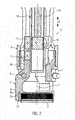
- Fig. 1 shows in schematic representation and in longitudinal section a closing unit 1 of a closing machine for closing containers, not shown with a closure 2.
- the closing unit 1 is shown in the illustrated embodiment in aseptic design and includes a partition wall 3 of the closing machine, a clean room area RR of a gray room GR separates.
- the partition wall 3 separates the closing unit 1 into a drive part 4 and a closing tool 5.
- the tool 5 a housing 6, in which a gripping device 7 is housed.
- the gripping device 7 is preferably replaceable housed in the housing 6 and can be exchanged for the handling of different closures. Especially with aseptic design, these components are gap-free and sealed mounted.
- the gripping device 7 includes in the illustrated embodiment, a plurality of gripping members 8 in the form of gripping segments, which are grouped around the center line 7 'of the gripping device 7.
- the term "gripping member” is intended to cover all structures capable of gripping and holding the shutter 2.
- Each gripping member 8 is pivotable about a substantially horizontal axis of rotation 9 in the form of a bolt or the like. In a gripping position for holding the shutter 2 and a release position for releasing the shutter.
- the rotation axis 9 divides the gripping member 8 into a lower arm 8a provided with gripping members 10 such as latching projections or corrugations or the like with which the shutter 2 can be securely held, and an upper arm 8b to which a magnetic actuator 11 for pivoting the gripping members 8 about the axis of rotation 9 and thus for opening and closing the gripping device 7 acts.
- the magnet actuation 11 preferably contains permanent magnets and is based on the known physical principle that poles of the same name repel from permanent magnets and attract different poles.
- the solenoid actuation 11 is executed in the illustrated embodiment in linear combination, wherein a first magnet 12 and a second magnet 13 in the axial direction next to each other along the center line 7 'on the second arm 8b of the gripping member 8 are.
- the two magnets are aligned so that they point with different poles in the direction of the center line 7 ', wherein in the illustrated embodiment, the upper magnet 12 with its north pole and the lower magnet 13 with its south pole in the direction of the center line 7'.
- the solenoid actuator 11 further includes a third magnet 14, which, however, is responsible for all gripping members 8.
- the third magnet 14 is preferably a ring magnet whose outer circumference has the north pole.
- the third magnet 14 is fixed to a support 15 in the form of a support rod which is coaxial with the center line 7 ', and in the direction of actuation B of his in Fig. 2 shown opposite to the first magnet 12 in a opposite position to the second magnet 13 and can be moved back. If the third magnet 14 is located at the level of the first magnets 12 of all gripping members 8, the gripping members 8 are pivoted into the in Fig. 2 shown closed position, the gripped closure 2 can be held and screwed. When this is done, the third magnet 14 moves down the center line 7 'until it faces the second magnet 13 of all the gripping members 8. Now takes place the attraction, which pivot the gripping members 8 about the axis of rotation 9 in an open position in which the shutter 2 is released.
- This type of solenoid actuation 11 is particularly suitable for the clean room or aseptic design Fig. 1 , here only the support rod 15 with the third magnet 14 in a closed, sleeve-like Auswerferstange 16 (permeable to magnetic fields) accommodated is.
- This ejector rod 16 can be easily sealed by a sleeve 17, which is sealingly secured around a passage opening 18 through the partition wall 3, and at the bottom of the ejector 16, again in turn, the passage opening sealingly attached.
- the drive movement with regard to the screw-on rotation can be transmitted to a rotary sleeve 20 via a gear coupling 19, for example.
- the rotary sleeve 20 transmits the rotation via a magnetic actuator in the form of a magnetic coupling 21 on an inner sleeve 22 to which the tool 5 is attached (preferably releasably via a corresponding coupling 23).
- the lifting movement for opening and closing the gripping members 8 also takes place via the magnetic coupling 21 on the tool 5, wherein the lifting movement is transmitted here only during the screwing movement.
- the movement of the support rod 15 is separate from the lifting movement and independent of the drive system.
- the drive movements can also by other means, such. B. be generated pneumatically, electrically or electromagnetically.
- stops 25 for the insertion depth of the closure 2 into the tool can be arranged.
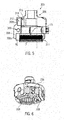
- the 3 and 4 show a modified embodiment of a closing tool 105, which differs from the embodiment according to the Fig. 1 and 2 only differs by a different arrangement of the magnets of the magnetic actuator 111.
- closing tool 105 which accommodated in the ejection bar 116 support rod 115 includes the in Fig. 4 shown magnet assembly 114, in which a plurality of magnets 114a to 114f are arranged circularly and with alternating polarity about the center line 7 ', so that alternately a south pole and a north pole to the outside, ie away from the center line 7'.
- the gripping members 8 in the form of gripping segments are here only provided with the first magnet 12, which on all three segments with the same polarity inwards, i. pointing to the center line 7 ', are arranged. In the illustrated embodiment, this is the north pole.
- the support rod 15 is not axially displaced longitudinally to the center line 7 ', but rotated about it, as indicated by the arrow D.
- each other poles come in a position opposite the first magnet 12 at the gripping segments position, wherein, like Fig. 4 shows, initially a repulsion takes place to close the gripping device, and in the next step, an attraction takes place and thus the gripping segments opens.
- This embodiment of the closing tool 105 is cleanroom or aseptiktauglich.
- Fig. 5 shows a further embodiment of a closing tool 305 according to the invention, which shows features of the two preceding embodiments, wherein identical or similar components are marked with reference numerals increased by 300 and not explained again.
- the closure tool 305 includes a plurality of gripping segments 308 which are pivotable about a pivot axis 309.
- the lower arm 308a formed thereby is provided with the gripping members 10 and the upper arm 308b carries a magnet 312.
- the counter magnet (s) 314 are fixed to a rotating ring 337 of the holder 306 such that the interaction between attraction for opening and opening already described above Repulsion to close the gripping device 311 results.
- the Fig. 6 and 7 show a further embodiment of a closing tool 205 according to the invention, which is characterized by a simple configuration.
- the closure tool 205 includes a gripping means 207 having a plurality of gripping members 208 in the form of gripping segments which are arranged in a circle around the center line 7 '.
- the gripping members 208 are, however, in the direction of the double arrow S on the center line 7 'to and away from her displaced, which can be effected by suitable guides, such as the indicated guide rod 226.
- the tool 205 also has a solenoid actuator 211 with first magnets 212 and opposed (third) magnets 214 arranged on concentric circles about the centerline 7 '.
- the closing tool 205 for a movement of the gripping members 208 in a gripping position and a release position with respect to the shutter 2, this time be designed by moving by the magnets 214 in a circle around the center line 7 'with each alternating Are installed polarity, so that by rotation of the holder 206 each have different polarities opposite the magnet 212.
- the magnets 214, 212 are fixed and installed in such a way that the same polarities are opposite to produce a repulsive force.
- the magnetic force and the gap L is adjusted so that the gripping members 208 surround a gap around the center line 7 ', which is at least equal, but preferably smaller than the diameter of the male closure 2.
- the gripping members 208 are what is particularly important here , provided on its underside with inlet slopes 37, so that the closure when placing the tool 205, the gripping members 208 against the repulsive force of the magnets 212, 214 apart and thereby the holding force when handling the closure 2 and the application of the closure 2 is applied.
- the gripping members 208 Upon removal of the tool 205 from the sealed container, the gripping members 208 return to their original position by the repulsive force of the magnets 212, 214.
- the closing tool 205 also has on its holder 206 a drive toothing 219 for applying the screwing movement.
- the magnets 214 are each received in brackets 236 which are individually adjustably attached to the bracket 206 so that the gap L between the magnets 212, 214 along the guide rod 226 can be adjusted.
- the closing tools according to the invention can also be used with other gripping members, such. Gripping arms, be formed, which have a greater distance from each other.
- Gripping arms be formed, which have a greater distance from each other.
- a special design for special forms of closures is possible.
Landscapes
- Engineering & Computer Science (AREA)
- Mechanical Engineering (AREA)
- Sealing Of Jars (AREA)
- Manipulator (AREA)
- Closing Of Containers (AREA)
- Filling Of Jars Or Cans And Processes For Cleaning And Sealing Jars (AREA)
Priority Applications (1)
| Application Number | Priority Date | Filing Date | Title |
|---|---|---|---|
| SI201230153T SI2497744T1 (sl) | 2011-03-09 | 2012-01-20 | Orodje za zapiranje |
Applications Claiming Priority (1)
| Application Number | Priority Date | Filing Date | Title |
|---|---|---|---|
| DE102011005306A DE102011005306A1 (de) | 2011-03-09 | 2011-03-09 | Verschließwerkzeug |
Publications (3)
| Publication Number | Publication Date |
|---|---|
| EP2497744A2 true EP2497744A2 (fr) | 2012-09-12 |
| EP2497744A3 EP2497744A3 (fr) | 2013-07-24 |
| EP2497744B1 EP2497744B1 (fr) | 2014-12-24 |
Family
ID=45592181
Family Applications (1)
| Application Number | Title | Priority Date | Filing Date |
|---|---|---|---|
| EP12151923.5A Active EP2497744B1 (fr) | 2011-03-09 | 2012-01-20 | Outil de fermeture |
Country Status (5)
| Country | Link |
|---|---|
| US (1) | US9388031B2 (fr) |
| EP (1) | EP2497744B1 (fr) |
| CN (1) | CN102674219B (fr) |
| DE (1) | DE102011005306A1 (fr) |
| SI (1) | SI2497744T1 (fr) |
Cited By (4)
| Publication number | Priority date | Publication date | Assignee | Title |
|---|---|---|---|---|
| EP2730533A3 (fr) * | 2012-11-09 | 2014-12-03 | Krones AG | Dispositif d'application d'une fermeture sur un récipient |
| EP2724976A3 (fr) * | 2012-10-29 | 2014-12-24 | Krones AG | Machine de fermeture pour récipients |
| IT201700047818A1 (it) * | 2017-05-03 | 2018-11-03 | Arol Spa | Testa di tappatura per applicazione di capsule su contenitori o bottiglie |
| EP3828127A1 (fr) * | 2019-11-29 | 2021-06-02 | KRONES Aktiengesellschaft | Dispositif de fermeture permettant de fermer les récipients |
Families Citing this family (13)
| Publication number | Priority date | Publication date | Assignee | Title |
|---|---|---|---|---|
| DE102012110751A1 (de) * | 2012-11-09 | 2014-05-15 | Krones Ag | Vorrichtung zum Aufbringen eines Verschlusses auf einen Behälter |
| CN104444982A (zh) * | 2013-09-17 | 2015-03-25 | 山东穆拉德生物医药科技有限公司 | 一种石榴汁灌装机抓瓶盖装置 |
| JP6177724B2 (ja) * | 2014-05-27 | 2017-08-09 | ファナック株式会社 | 工具把持機構 |
| IT201600085761A1 (it) | 2016-08-17 | 2018-02-17 | Arol Spa | "Mandrino di tappatura auto-regolante per applicare elementi di chiusura su contenitori" |
| IT201600106114A1 (it) * | 2016-10-21 | 2018-04-21 | Arol Spa | Gruppo di presa per testa di tappatura per applicazione di capsule su contenitori o bottiglie |
| IT201600106129A1 (it) * | 2016-10-21 | 2018-04-21 | Arol Spa | Testa di tappatura per applicazione di capsule su contenitori o bottiglie |
| US10981766B2 (en) * | 2016-12-06 | 2021-04-20 | Michael P. Scott | Capping chuck assembly |
| US10961100B2 (en) | 2018-08-31 | 2021-03-30 | Industrial Technology Research Institute H | Magnetic screwdriver device |
| US10780439B2 (en) | 2018-08-31 | 2020-09-22 | Industrial Technology Research Institute | Magnetic screwdriver device |
| DE102019209755B4 (de) * | 2019-07-03 | 2021-08-05 | Festo Se & Co. Kg | Verbindung zwischen Grundkörper und Greifeinheit einer Greifvorrichtung |
| EP3763666B1 (fr) * | 2019-07-12 | 2021-10-06 | Unilogo Robotics Sp. z o.o. | Préhenseur pour une machine de bouchage de bouteille |
| CN111302286A (zh) * | 2020-03-11 | 2020-06-19 | 英攀东 | 一种玻璃罐装食品自动加盖设备 |
| WO2023117062A1 (fr) * | 2021-12-21 | 2023-06-29 | Sidel Participations | Préhenseur magnétique permettant de manipuler des récipients conçus pour contenir un produit versable |
Citations (1)
| Publication number | Priority date | Publication date | Assignee | Title |
|---|---|---|---|---|
| WO2004009484A1 (fr) | 2002-07-19 | 2004-01-29 | Alcoa Deutschland Gmbh | Cone de fermeture |
Family Cites Families (28)
| Publication number | Priority date | Publication date | Assignee | Title |
|---|---|---|---|---|
| US871998A (en) * | 1906-06-13 | 1907-11-26 | Georg Kirkegaard | Bottle-capping machine. |
| US2030188A (en) * | 1934-12-08 | 1936-02-11 | Cons Packaging Machinery Corp | Magnetic capping chuck |
| GB793276A (en) * | 1955-01-12 | 1958-04-16 | Otto Hofliger | Method and device for screwing threaded caps on to containers |
| DE1006292B (de) * | 1955-01-12 | 1957-04-11 | Hoefliger & Karg | Verfahren und Vorrichtung zum Aufschrauben von Schraubkappen |
| GB1484262A (en) * | 1973-09-27 | 1977-09-01 | Metal Box Co Ltd | Capping machine |
| US4633646A (en) * | 1985-10-29 | 1987-01-06 | Aluminum Company Of America | Capping head |
| US4674264A (en) * | 1986-02-03 | 1987-06-23 | Aluminum Company Of America | Screwcapping head with a hysteresis clutch |
| DE3640417A1 (de) * | 1986-11-26 | 1988-06-09 | Bosch Gmbh Robert | Schraubkopf an behaelterverschliessmaschine |
| US5313765A (en) * | 1991-11-04 | 1994-05-24 | Anderson-Martin Machine Company | Capping machine head with magnetic clutch |
| IT1264178B1 (it) * | 1993-07-28 | 1996-09-23 | Azionaria Costruzioni Acma Spa | Unita' tappatrice per l'assemblaggio automatico di flaconi a pompa. |
| AT640U1 (de) * | 1993-10-22 | 1996-02-26 | Sez Semiconduct Equip Zubehoer | Greifer für halbleiterwafer und andere scheibenförmige gegenstände |
| US5479762B1 (en) * | 1994-05-06 | 1997-07-15 | Dowbrands Lp | Carrier puck |
| CA2162623A1 (fr) | 1995-08-11 | 1997-02-12 | Dennis Winski | Appareil utilise pour la mise en place de couvercle filete et de pompe |
| US6041571A (en) * | 1998-01-29 | 2000-03-28 | Fowler Products Company | Magnetic coupling for a capping apparatus |
| US6076875A (en) * | 1998-02-18 | 2000-06-20 | Systems, Machines, Automation Components, Corporation | Gripper for linear voice coil actuator |
| JP2000343473A (ja) * | 1999-06-03 | 2000-12-12 | Smc Corp | 平行開閉チャック |
| US6386609B1 (en) * | 1999-06-12 | 2002-05-14 | Applied Materials, Inc. | Gripper design to reduce backlash |
| JP3293802B2 (ja) * | 1999-07-07 | 2002-06-17 | エスエムシー株式会社 | 位置検出機能付きチャック |
| US6626476B1 (en) * | 2000-07-18 | 2003-09-30 | Applied Materials, Inc. | Robotic gripper apparatus |
| JP2006102920A (ja) * | 2004-10-08 | 2006-04-20 | Fanuc Ltd | 把握型ハンド |
| ITPR20050024A1 (it) * | 2005-05-19 | 2006-11-20 | Rejves Srl | Testa avvitatrice per avvitare la ghiera di una pompetta a grilletto su di un recipiente. |
| US7699087B2 (en) * | 2005-06-29 | 2010-04-20 | Schenck Rotec Gmbh | Method for mounting a pneumatic tire |
| DE102005041929A1 (de) * | 2005-09-03 | 2007-03-08 | Krones Ag | Greifer für Behälter |
| ITTO20060706A1 (it) * | 2006-10-02 | 2008-04-03 | Arol Spa | "testa di avvitatura e rullatura per l'applicazione di capsule pre-filettate" |
| DE102008055617B4 (de) * | 2008-11-03 | 2015-08-27 | Khs Gmbh | Klammer zum Ergreifen von Flaschenhälsen, insbesondere von PET-Flaschen |
| DE102008062315A1 (de) * | 2008-12-11 | 2010-06-17 | Khs Corpoplast Gmbh & Co. Kg | Verfahren und Vorrichtung zur Übergabe von Werkstücken |
| DE102009009822A1 (de) * | 2009-02-20 | 2010-08-26 | Krones Ag | Vorrichtung zum Verschließen von Behältnissen mit berührungsloser Drehmomentenerzeugung |
| DE102009017109A1 (de) * | 2009-04-15 | 2010-10-28 | Khs Gmbh | Verschließer für Schraubkappen bzw. -verschlüsse |
-
2011
- 2011-03-09 DE DE102011005306A patent/DE102011005306A1/de not_active Withdrawn
-
2012
- 2012-01-20 EP EP12151923.5A patent/EP2497744B1/fr active Active
- 2012-01-20 SI SI201230153T patent/SI2497744T1/sl unknown
- 2012-02-24 US US13/404,417 patent/US9388031B2/en active Active
- 2012-03-09 CN CN201210062194.9A patent/CN102674219B/zh active Active
Patent Citations (1)
| Publication number | Priority date | Publication date | Assignee | Title |
|---|---|---|---|---|
| WO2004009484A1 (fr) | 2002-07-19 | 2004-01-29 | Alcoa Deutschland Gmbh | Cone de fermeture |
Cited By (5)
| Publication number | Priority date | Publication date | Assignee | Title |
|---|---|---|---|---|
| EP2724976A3 (fr) * | 2012-10-29 | 2014-12-24 | Krones AG | Machine de fermeture pour récipients |
| EP2730533A3 (fr) * | 2012-11-09 | 2014-12-03 | Krones AG | Dispositif d'application d'une fermeture sur un récipient |
| IT201700047818A1 (it) * | 2017-05-03 | 2018-11-03 | Arol Spa | Testa di tappatura per applicazione di capsule su contenitori o bottiglie |
| WO2018203244A1 (fr) * | 2017-05-03 | 2018-11-08 | Arol S.P.A. | Tête de capsulage permettant la pose de capsules sur des récipients ou des bouteilles |
| EP3828127A1 (fr) * | 2019-11-29 | 2021-06-02 | KRONES Aktiengesellschaft | Dispositif de fermeture permettant de fermer les récipients |
Also Published As
| Publication number | Publication date |
|---|---|
| US9388031B2 (en) | 2016-07-12 |
| EP2497744A3 (fr) | 2013-07-24 |
| CN102674219B (zh) | 2015-02-11 |
| SI2497744T1 (sl) | 2015-04-30 |
| US20120227355A1 (en) | 2012-09-13 |
| EP2497744B1 (fr) | 2014-12-24 |
| DE102011005306A1 (de) | 2012-09-13 |
| CN102674219A (zh) | 2012-09-19 |
Similar Documents
| Publication | Publication Date | Title |
|---|---|---|
| EP2497744B1 (fr) | Outil de fermeture | |
| EP1924515B1 (fr) | Dispositif de prehension pour recipient | |
| EP3966476B1 (fr) | Dispositif de transfert stérile de produit entre un récipient et un isolateur | |
| EP1868746B1 (fr) | Bride de fixation pour fixer des recipients | |
| DE69104583T2 (de) | Greifklemme und damit ausgerüstete behandlungsmaschine für gegenstände, insbesondere flaschen. | |
| EP3433189B1 (fr) | Dispositif de transport pour transporter des récipients | |
| EP3658478B1 (fr) | Dispositif de retenue d'un récipient et dispositif de traitement | |
| DE102008022848A1 (de) | PET-Flaschengreifer | |
| EP3919419A1 (fr) | Dispositif de maintien d'un récipient et dispositif de manutention des récipients | |
| DE102009025907A1 (de) | Vorrichtung und Verfahren zur Behandlung von Behältern | |
| DE102008029711A1 (de) | Wechselbares Greifelement zum Transportieren von Behältnissen | |
| EP2631190B1 (fr) | Dispositif de préhension | |
| DE102008055618A1 (de) | Klammer zum Ergreifen von Flaschenhälsen, insbesondere von PET-Flaschen | |
| DE102014103181A1 (de) | Verschlussvorrichtung mit Zustandsanzeige | |
| DE102014210401A1 (de) | Stopfensetzwerkzeug | |
| WO2017129316A1 (fr) | Élément de préhension pour porte-récipient, porte-récipient et voie de transport de récipients | |
| EP1574460B1 (fr) | Dispositif de transport pour bouteilles ou récipients similaires | |
| DE19740892A1 (de) | Transportstern für Gefäße | |
| CH712686B1 (de) | Pipettiervorrichtung zum Aspirieren und Dispensieren von Flüssigkeiten. | |
| DE102018203788A1 (de) | Vorrichtung zum Greifen zumindest eines Objekts, insbesondere eines pharmazeutischen Behältnisses | |
| DE102017119766A1 (de) | Vorrichtung und Verfahren zum Transport von Behältern | |
| DE102021102822A1 (de) | Vorrichtung und Verfahren zum Transport von Behältern | |
| EP1761434B1 (fr) | Dispositif et procede pour monter des pompes de pulverisation et des elements similaires sur des recipients et pour les verrouiller | |
| EP0508048A1 (fr) | Cartouche pour courrier par tube | |
| DE102023123402A1 (de) | Sternradförderer zum Fördern von Behältern in einer Getränkeabfüllanlage |
Legal Events
| Date | Code | Title | Description |
|---|---|---|---|
| PUAI | Public reference made under article 153(3) epc to a published international application that has entered the european phase |
Free format text: ORIGINAL CODE: 0009012 |
|
| AK | Designated contracting states |
Kind code of ref document: A2 Designated state(s): AL AT BE BG CH CY CZ DE DK EE ES FI FR GB GR HR HU IE IS IT LI LT LU LV MC MK MT NL NO PL PT RO RS SE SI SK SM TR |
|
| AX | Request for extension of the european patent |
Extension state: BA ME |
|
| PUAL | Search report despatched |
Free format text: ORIGINAL CODE: 0009013 |
|
| AK | Designated contracting states |
Kind code of ref document: A3 Designated state(s): AL AT BE BG CH CY CZ DE DK EE ES FI FR GB GR HR HU IE IS IT LI LT LU LV MC MK MT NL NO PL PT RO RS SE SI SK SM TR |
|
| AX | Request for extension of the european patent |
Extension state: BA ME |
|
| RIC1 | Information provided on ipc code assigned before grant |
Ipc: B67B 3/20 20060101AFI20130620BHEP |
|
| 17P | Request for examination filed |
Effective date: 20140122 |
|
| RBV | Designated contracting states (corrected) |
Designated state(s): AL AT BE BG CH CY CZ DE DK EE ES FI FR GB GR HR HU IE IS IT LI LT LU LV MC MK MT NL NO PL PT RO RS SE SI SK SM TR |
|
| GRAP | Despatch of communication of intention to grant a patent |
Free format text: ORIGINAL CODE: EPIDOSNIGR1 |
|
| INTG | Intention to grant announced |
Effective date: 20140903 |
|
| GRAS | Grant fee paid |
Free format text: ORIGINAL CODE: EPIDOSNIGR3 |
|
| GRAA | (expected) grant |
Free format text: ORIGINAL CODE: 0009210 |
|
| AK | Designated contracting states |
Kind code of ref document: B1 Designated state(s): AL AT BE BG CH CY CZ DE DK EE ES FI FR GB GR HR HU IE IS IT LI LT LU LV MC MK MT NL NO PL PT RO RS SE SI SK SM TR |
|
| REG | Reference to a national code |
Ref country code: GB Ref legal event code: FG4D Free format text: NOT ENGLISH |
|
| REG | Reference to a national code |
Ref country code: CH Ref legal event code: EP |
|
| REG | Reference to a national code |
Ref country code: IE Ref legal event code: FG4D Free format text: LANGUAGE OF EP DOCUMENT: GERMAN |
|
| REG | Reference to a national code |
Ref country code: AT Ref legal event code: REF Ref document number: 703013 Country of ref document: AT Kind code of ref document: T Effective date: 20150115 |
|
| REG | Reference to a national code |
Ref country code: DE Ref legal event code: R096 Ref document number: 502012001877 Country of ref document: DE Effective date: 20150219 |
|
| REG | Reference to a national code |
Ref country code: NL Ref legal event code: VDEP Effective date: 20141224 |
|
| PG25 | Lapsed in a contracting state [announced via postgrant information from national office to epo] |
Ref country code: FI Free format text: LAPSE BECAUSE OF FAILURE TO SUBMIT A TRANSLATION OF THE DESCRIPTION OR TO PAY THE FEE WITHIN THE PRESCRIBED TIME-LIMIT Effective date: 20141224 Ref country code: NO Free format text: LAPSE BECAUSE OF FAILURE TO SUBMIT A TRANSLATION OF THE DESCRIPTION OR TO PAY THE FEE WITHIN THE PRESCRIBED TIME-LIMIT Effective date: 20150324 Ref country code: LT Free format text: LAPSE BECAUSE OF FAILURE TO SUBMIT A TRANSLATION OF THE DESCRIPTION OR TO PAY THE FEE WITHIN THE PRESCRIBED TIME-LIMIT Effective date: 20141224 |
|
| REG | Reference to a national code |
Ref country code: LT Ref legal event code: MG4D |
|
| PG25 | Lapsed in a contracting state [announced via postgrant information from national office to epo] |
Ref country code: RS Free format text: LAPSE BECAUSE OF FAILURE TO SUBMIT A TRANSLATION OF THE DESCRIPTION OR TO PAY THE FEE WITHIN THE PRESCRIBED TIME-LIMIT Effective date: 20141224 Ref country code: GR Free format text: LAPSE BECAUSE OF FAILURE TO SUBMIT A TRANSLATION OF THE DESCRIPTION OR TO PAY THE FEE WITHIN THE PRESCRIBED TIME-LIMIT Effective date: 20150325 Ref country code: HR Free format text: LAPSE BECAUSE OF FAILURE TO SUBMIT A TRANSLATION OF THE DESCRIPTION OR TO PAY THE FEE WITHIN THE PRESCRIBED TIME-LIMIT Effective date: 20141224 Ref country code: LV Free format text: LAPSE BECAUSE OF FAILURE TO SUBMIT A TRANSLATION OF THE DESCRIPTION OR TO PAY THE FEE WITHIN THE PRESCRIBED TIME-LIMIT Effective date: 20141224 Ref country code: SE Free format text: LAPSE BECAUSE OF FAILURE TO SUBMIT A TRANSLATION OF THE DESCRIPTION OR TO PAY THE FEE WITHIN THE PRESCRIBED TIME-LIMIT Effective date: 20141224 |
|
| PG25 | Lapsed in a contracting state [announced via postgrant information from national office to epo] |
Ref country code: NL Free format text: LAPSE BECAUSE OF FAILURE TO SUBMIT A TRANSLATION OF THE DESCRIPTION OR TO PAY THE FEE WITHIN THE PRESCRIBED TIME-LIMIT Effective date: 20141224 |
|
| PG25 | Lapsed in a contracting state [announced via postgrant information from national office to epo] |
Ref country code: RO Free format text: LAPSE BECAUSE OF FAILURE TO SUBMIT A TRANSLATION OF THE DESCRIPTION OR TO PAY THE FEE WITHIN THE PRESCRIBED TIME-LIMIT Effective date: 20141224 Ref country code: CZ Free format text: LAPSE BECAUSE OF FAILURE TO SUBMIT A TRANSLATION OF THE DESCRIPTION OR TO PAY THE FEE WITHIN THE PRESCRIBED TIME-LIMIT Effective date: 20141224 Ref country code: EE Free format text: LAPSE BECAUSE OF FAILURE TO SUBMIT A TRANSLATION OF THE DESCRIPTION OR TO PAY THE FEE WITHIN THE PRESCRIBED TIME-LIMIT Effective date: 20141224 Ref country code: ES Free format text: LAPSE BECAUSE OF FAILURE TO SUBMIT A TRANSLATION OF THE DESCRIPTION OR TO PAY THE FEE WITHIN THE PRESCRIBED TIME-LIMIT Effective date: 20141224 Ref country code: SK Free format text: LAPSE BECAUSE OF FAILURE TO SUBMIT A TRANSLATION OF THE DESCRIPTION OR TO PAY THE FEE WITHIN THE PRESCRIBED TIME-LIMIT Effective date: 20141224 |
|
| REG | Reference to a national code |
Ref country code: CH Ref legal event code: PL |
|
| PG25 | Lapsed in a contracting state [announced via postgrant information from national office to epo] |
Ref country code: IS Free format text: LAPSE BECAUSE OF FAILURE TO SUBMIT A TRANSLATION OF THE DESCRIPTION OR TO PAY THE FEE WITHIN THE PRESCRIBED TIME-LIMIT Effective date: 20150424 Ref country code: LU Free format text: LAPSE BECAUSE OF FAILURE TO SUBMIT A TRANSLATION OF THE DESCRIPTION OR TO PAY THE FEE WITHIN THE PRESCRIBED TIME-LIMIT Effective date: 20150120 Ref country code: PL Free format text: LAPSE BECAUSE OF FAILURE TO SUBMIT A TRANSLATION OF THE DESCRIPTION OR TO PAY THE FEE WITHIN THE PRESCRIBED TIME-LIMIT Effective date: 20141224 |
|
| REG | Reference to a national code |
Ref country code: DE Ref legal event code: R097 Ref document number: 502012001877 Country of ref document: DE |
|
| PG25 | Lapsed in a contracting state [announced via postgrant information from national office to epo] |
Ref country code: MC Free format text: LAPSE BECAUSE OF FAILURE TO SUBMIT A TRANSLATION OF THE DESCRIPTION OR TO PAY THE FEE WITHIN THE PRESCRIBED TIME-LIMIT Effective date: 20141224 |
|
| PG25 | Lapsed in a contracting state [announced via postgrant information from national office to epo] |
Ref country code: CH Free format text: LAPSE BECAUSE OF NON-PAYMENT OF DUE FEES Effective date: 20150131 Ref country code: LI Free format text: LAPSE BECAUSE OF NON-PAYMENT OF DUE FEES Effective date: 20150131 Ref country code: DK Free format text: LAPSE BECAUSE OF FAILURE TO SUBMIT A TRANSLATION OF THE DESCRIPTION OR TO PAY THE FEE WITHIN THE PRESCRIBED TIME-LIMIT Effective date: 20141224 |
|
| PLBE | No opposition filed within time limit |
Free format text: ORIGINAL CODE: 0009261 |
|
| REG | Reference to a national code |
Ref country code: IE Ref legal event code: MM4A |
|
| STAA | Information on the status of an ep patent application or granted ep patent |
Free format text: STATUS: NO OPPOSITION FILED WITHIN TIME LIMIT |
|
| 26N | No opposition filed |
Effective date: 20150925 |
|
| REG | Reference to a national code |
Ref country code: FR Ref legal event code: PLFP Year of fee payment: 5 |
|
| PG25 | Lapsed in a contracting state [announced via postgrant information from national office to epo] |
Ref country code: IE Free format text: LAPSE BECAUSE OF NON-PAYMENT OF DUE FEES Effective date: 20150120 |
|
| GBPC | Gb: european patent ceased through non-payment of renewal fee |
Effective date: 20160120 |
|
| PG25 | Lapsed in a contracting state [announced via postgrant information from national office to epo] |
Ref country code: GB Free format text: LAPSE BECAUSE OF NON-PAYMENT OF DUE FEES Effective date: 20160120 |
|
| REG | Reference to a national code |
Ref country code: FR Ref legal event code: PLFP Year of fee payment: 6 |
|
| PG25 | Lapsed in a contracting state [announced via postgrant information from national office to epo] |
Ref country code: MT Free format text: LAPSE BECAUSE OF FAILURE TO SUBMIT A TRANSLATION OF THE DESCRIPTION OR TO PAY THE FEE WITHIN THE PRESCRIBED TIME-LIMIT Effective date: 20141224 |
|
| PG25 | Lapsed in a contracting state [announced via postgrant information from national office to epo] |
Ref country code: SM Free format text: LAPSE BECAUSE OF FAILURE TO SUBMIT A TRANSLATION OF THE DESCRIPTION OR TO PAY THE FEE WITHIN THE PRESCRIBED TIME-LIMIT Effective date: 20141224 Ref country code: HU Free format text: LAPSE BECAUSE OF FAILURE TO SUBMIT A TRANSLATION OF THE DESCRIPTION OR TO PAY THE FEE WITHIN THE PRESCRIBED TIME-LIMIT; INVALID AB INITIO Effective date: 20120120 Ref country code: BG Free format text: LAPSE BECAUSE OF FAILURE TO SUBMIT A TRANSLATION OF THE DESCRIPTION OR TO PAY THE FEE WITHIN THE PRESCRIBED TIME-LIMIT Effective date: 20141224 |
|
| PG25 | Lapsed in a contracting state [announced via postgrant information from national office to epo] |
Ref country code: CY Free format text: LAPSE BECAUSE OF FAILURE TO SUBMIT A TRANSLATION OF THE DESCRIPTION OR TO PAY THE FEE WITHIN THE PRESCRIBED TIME-LIMIT Effective date: 20141224 |
|
| PG25 | Lapsed in a contracting state [announced via postgrant information from national office to epo] |
Ref country code: PT Free format text: LAPSE BECAUSE OF FAILURE TO SUBMIT A TRANSLATION OF THE DESCRIPTION OR TO PAY THE FEE WITHIN THE PRESCRIBED TIME-LIMIT Effective date: 20150424 Ref country code: BE Free format text: LAPSE BECAUSE OF NON-PAYMENT OF DUE FEES Effective date: 20150131 |
|
| PG25 | Lapsed in a contracting state [announced via postgrant information from national office to epo] |
Ref country code: TR Free format text: LAPSE BECAUSE OF FAILURE TO SUBMIT A TRANSLATION OF THE DESCRIPTION OR TO PAY THE FEE WITHIN THE PRESCRIBED TIME-LIMIT Effective date: 20141224 |
|
| REG | Reference to a national code |
Ref country code: FR Ref legal event code: PLFP Year of fee payment: 7 |
|
| REG | Reference to a national code |
Ref country code: AT Ref legal event code: MM01 Ref document number: 703013 Country of ref document: AT Kind code of ref document: T Effective date: 20170120 |
|
| PG25 | Lapsed in a contracting state [announced via postgrant information from national office to epo] |
Ref country code: AT Free format text: LAPSE BECAUSE OF NON-PAYMENT OF DUE FEES Effective date: 20170120 |
|
| PG25 | Lapsed in a contracting state [announced via postgrant information from national office to epo] |
Ref country code: MK Free format text: LAPSE BECAUSE OF FAILURE TO SUBMIT A TRANSLATION OF THE DESCRIPTION OR TO PAY THE FEE WITHIN THE PRESCRIBED TIME-LIMIT Effective date: 20141224 |
|
| PG25 | Lapsed in a contracting state [announced via postgrant information from national office to epo] |
Ref country code: AL Free format text: LAPSE BECAUSE OF FAILURE TO SUBMIT A TRANSLATION OF THE DESCRIPTION OR TO PAY THE FEE WITHIN THE PRESCRIBED TIME-LIMIT Effective date: 20141224 |
|
| P01 | Opt-out of the competence of the unified patent court (upc) registered |
Effective date: 20230523 |
|
| PGFP | Annual fee paid to national office [announced via postgrant information from national office to epo] |
Ref country code: FR Payment date: 20251208 Year of fee payment: 15 |
|
| PGFP | Annual fee paid to national office [announced via postgrant information from national office to epo] |
Ref country code: SI Payment date: 20251215 Year of fee payment: 15 |
|
| PGFP | Annual fee paid to national office [announced via postgrant information from national office to epo] |
Ref country code: DE Payment date: 20251203 Year of fee payment: 15 |
|
| PGFP | Annual fee paid to national office [announced via postgrant information from national office to epo] |
Ref country code: IT Payment date: 20251219 Year of fee payment: 15 |