EP2497901A2 - Ancrage coulissant - Google Patents
Ancrage coulissant Download PDFInfo
- Publication number
- EP2497901A2 EP2497901A2 EP12152106A EP12152106A EP2497901A2 EP 2497901 A2 EP2497901 A2 EP 2497901A2 EP 12152106 A EP12152106 A EP 12152106A EP 12152106 A EP12152106 A EP 12152106A EP 2497901 A2 EP2497901 A2 EP 2497901A2
- Authority
- EP
- European Patent Office
- Prior art keywords
- anchor
- sleeve
- sliding
- rock
- tube
- Prior art date
- Legal status (The legal status is an assumption and is not a legal conclusion. Google has not performed a legal analysis and makes no representation as to the accuracy of the status listed.)
- Withdrawn
Links
- 239000011435 rock Substances 0.000 claims abstract description 70
- 239000000463 material Substances 0.000 claims abstract description 8
- 229910000831 Steel Inorganic materials 0.000 claims abstract description 6
- 239000010959 steel Substances 0.000 claims abstract description 6
- 239000004033 plastic Substances 0.000 claims abstract description 5
- 229920003023 plastic Polymers 0.000 claims abstract description 5
- 229920002430 Fibre-reinforced plastic Polymers 0.000 claims abstract description 3
- 239000011151 fibre-reinforced plastic Substances 0.000 claims abstract description 3
- 239000005060 rubber Substances 0.000 claims abstract description 3
- 239000000126 substance Substances 0.000 claims description 13
- 238000013016 damping Methods 0.000 claims description 11
- 238000005065 mining Methods 0.000 claims description 6
- 239000002184 metal Substances 0.000 claims description 4
- 230000000284 resting effect Effects 0.000 claims description 2
- 239000000834 fixative Substances 0.000 description 8
- 230000003068 static effect Effects 0.000 description 4
- 230000006835 compression Effects 0.000 description 3
- 238000007906 compression Methods 0.000 description 3
- 238000003825 pressing Methods 0.000 description 3
- 239000000853 adhesive Substances 0.000 description 2
- 230000001070 adhesive effect Effects 0.000 description 2
- 230000005540 biological transmission Effects 0.000 description 2
- 239000003795 chemical substances by application Substances 0.000 description 2
- 229920005989 resin Polymers 0.000 description 2
- 239000011347 resin Substances 0.000 description 2
- 230000035939 shock Effects 0.000 description 2
- 229920003002 synthetic resin Polymers 0.000 description 2
- 239000000057 synthetic resin Substances 0.000 description 2
- 229920001187 thermosetting polymer Polymers 0.000 description 2
- XLYOFNOQVPJJNP-UHFFFAOYSA-N water Substances O XLYOFNOQVPJJNP-UHFFFAOYSA-N 0.000 description 2
- 240000007124 Brassica oleracea Species 0.000 description 1
- 235000003899 Brassica oleracea var acephala Nutrition 0.000 description 1
- 235000011301 Brassica oleracea var capitata Nutrition 0.000 description 1
- 235000001169 Brassica oleracea var oleracea Nutrition 0.000 description 1
- 230000005483 Hooke's law Effects 0.000 description 1
- 239000006096 absorbing agent Substances 0.000 description 1
- 238000010521 absorption reaction Methods 0.000 description 1
- 238000004873 anchoring Methods 0.000 description 1
- 239000011248 coating agent Substances 0.000 description 1
- 238000000576 coating method Methods 0.000 description 1
- 230000005489 elastic deformation Effects 0.000 description 1
- 239000011152 fibreglass Substances 0.000 description 1
- 239000012530 fluid Substances 0.000 description 1
- 230000005484 gravity Effects 0.000 description 1
- 230000000977 initiatory effect Effects 0.000 description 1
- 238000012806 monitoring device Methods 0.000 description 1
- 239000004570 mortar (masonry) Substances 0.000 description 1
- 239000007787 solid Substances 0.000 description 1
- 239000000758 substrate Substances 0.000 description 1
- 239000000725 suspension Substances 0.000 description 1
- 229920001169 thermoplastic Polymers 0.000 description 1
- 239000004416 thermosoftening plastic Substances 0.000 description 1
- 230000005641 tunneling Effects 0.000 description 1
Images


Classifications
-
- E—FIXED CONSTRUCTIONS
- E21—EARTH OR ROCK DRILLING; MINING
- E21D—SHAFTS; TUNNELS; GALLERIES; LARGE UNDERGROUND CHAMBERS
- E21D21/00—Anchoring-bolts for roof, floor in galleries or longwall working, or shaft-lining protection
- E21D21/0026—Anchoring-bolts for roof, floor in galleries or longwall working, or shaft-lining protection characterised by constructional features of the bolts
- E21D21/0033—Anchoring-bolts for roof, floor in galleries or longwall working, or shaft-lining protection characterised by constructional features of the bolts having a jacket or outer tube
-
- E—FIXED CONSTRUCTIONS
- E21—EARTH OR ROCK DRILLING; MINING
- E21D—SHAFTS; TUNNELS; GALLERIES; LARGE UNDERGROUND CHAMBERS
- E21D21/00—Anchoring-bolts for roof, floor in galleries or longwall working, or shaft-lining protection
- E21D21/008—Anchoring or tensioning means
Definitions
- the present invention relates to a sliding anchor according to the preamble of claim 1.
- rock anchors In mining and tunneling rock anchors are used to prevent rock movements of the upcoming rock, to slow down or to secure larger flakes of pending rock and thus to allow safe operation. Two functional principles are known, some of which are combined.
- anchoring of the anchor takes place by means of frictional engagement, wherein mechanical rock anchors or rock anchors generally also have an expansion sleeve.
- anchor pipes In chemical rock anchors anchor pipes are connected with a thermosetting mortar or synthetic resin as a fixing material cohesively with the substrate or the upcoming rock.
- the rock anchors are incorporated with or without bias in the upcoming rock.
- An anchor plate is generally located on the Anchor nut on and an internal thread of the anchor nut engages in an external thread of a rod projection of an anchor tube. From a predetermined tensile force in the anchor tube or a compressive force on the anchor plate, wherein the rock rests on the anchor plate, the anchor nut can realize a certain sliding on the anchor tube as a rod projection and thereby allow an increase in the length of the sliding anchor.
- the sliding anchor thus requires for the sliding function a large rod projection in the working space, z. B. cleats, outside of the rock.
- the DE 29 04 778 A1 shows a monitoring device for detecting and displaying Firstenterrorismen with an elongated above the ridge to be anchored in the hanging wall suspension device, at its from the firestop protruding lower end mounted on a length changes responsive sensing device for displaying a Firstenterrorism, one of the support device relative to this slidably attached holding device for the thereto by gravity automatically downwardly pivotally suspended sensing device, by a locking device for automatically latching locking the raised in a raised position sensing device, and by a mounted at the lower end of the support device Ausklinkvorraum to solve the lock at a predetermined relative movement relative to the holding device ,
- the object of the present invention is therefore to provide a sliding anchor available, in which with a low technical
- a chemical sliding anchor in particular for use in mining, for cohesive attachment to rock in a bore with a fixative, comprising an anchor tube, preferably an anchor nut, a, preferably supported by the anchor nut, anchor plate for resting on the rock, wherein in the sliding anchor an elastic element, in particular a spring, is integrated and an increase in length of the sliding anchor for a sliding function with a spring travel, d. H. an elastic deformation, the elastic element is realized.
- the elastic element in particular the spring, as a separate component independently of the anchor tube can absorb both static and dynamic forces. At the anchor tube acting static and dynamic tensile forces can thus be absorbed by the spring. In particular, this dynamic loads can be damped and occurring static tensile forces on the anchor tube by increasing the length of the rock anchor due to a spring travel of the spring causes an increase in length of the sliding anchor and thereby the male to be absorbed by the sliding anchor tensile forces can be reduced.
- an unforeseen anchor breakage of the sliding anchor can be effectively avoided and due to the good pick-up even for dynamic loads, the risk of failure under dynamic loads, eg. B. in mountain strikes or shocks are significantly reduced in the sliding anchor.
- the spring travel of the sliding anchor is limited in an advantageous manner and thereby also limits the possible sliding of the sliding anchor.
- advantageously the possible deformation path and the possible deformation of the rock on the sliding anchor can be limited.
- the sliding anchor comprises a sleeve and within the sleeve, the elastic element is arranged and / or a change in length of the elastic element is aligned in the direction of a longitudinal axis of the anchor tube and / or the sliding anchor is provided with a damping element for receiving dynamic forces and / or Elastic element is an additional component in addition to the anchor tube.
- the damping element serves for additional absorption of dynamic forces and can be used, for example, as a folding plate, as a spring or as an elastic plastic, for.
- a thermoplastic, thermosetting or elastomeric plastic, and in particular as a damping element a movable piston within a cylinder with a fluid, eg. As oil or water, be formed.
- a damping element with a piston and cylinder as a damping element corresponds for example in its technical structure and its function to the shock absorber in a motor vehicle.
- the anchor tube is arranged within the sleeve and preferably the elastic element is arranged between the anchor tube and the sleeve.
- the elastic element rests at one end on a sleeve support element connected to the sleeve and at another end on an anchor tube support element connected to the anchor tube and / or the sleeve is closed by a closing cap in the region of the anchor tube support element.
- the sleeve support member is formed as a plate having an opening and in the opening of the plate, the anchor tube is arranged.
- the anchor tube is thus axially displaceable in the opening of the plate in the direction of a longitudinal axis of the anchor tube and radially mounted on the opening of the plate.
- the Ankerrohrauflageelement is designed as a support ring.
- the support ring can be integral with the anchor tube or as separate, with the anchor tube material, form and / or non-positively connected component may be formed. With the support ring to be absorbed by the anchor tube forces are transmitted from the elastic element, in particular the spring, to the anchor tube.
- the Ankerrohrauflageelement in particular completely, within a sleeve enclosed by the, preferably cylindrical, sleeve space is arranged.
- the sleeve is arranged in the region of a rear end of the anchor tube for arranging the sleeve within a bore on the rock and the anchor nut is attached directly or indirectly to the anchor tube and preferably the sleeve forms the integral connection between the fixation substance and the rock a bore or the sleeve is arranged in the region of the front end of the anchor tube for arranging the sleeve outside the bore on the rock and the anchor plate is directly or indirectly on the sleeve or the sleeve support member, wherein the anchor plate rests on a rock side on the rock and on a sleeve side rests on the sleeve or the sleeve support member and the rock side is formed opposite the sleeve side of the anchor plate or the sleeve is arranged in the region of the front end of the anchor tube for the arrangement of the sleeve within the bore on the rock and the Sleeve is connected to the anchor plate and / or the anchor
- the anchor tube is at least partially, in particular completely, made of metal, for. As steel, or, preferably fiber reinforced plastic.
- the spring is a helical spring, an evolute spring, an annular spring, a folding plate or an elastic plastic, for. B. a rubber spring, formed.
- the glide path is substantially d. H. at least 50%, 80% or 90%, realized by a spring travel of the elastic element.
- the glide path i. H. the length enlargement of the sliding anchor
- a function eg. B. directly proportional to the change in length, in particular compression, of the elastic element, in particular by the elastic element
- the mechanism comprises an axially movable sleeve.
- the anchor tube includes a hollow tube as an interior and within the anchor tube is the fixative, z. B. in a bag or a cartridge arranged.
- the fixing agent is, for example, a two-component synthetic resin having an adhesive component and a curing component.
- the adhesive and curing components are first separated in the interior, e.g. B. in a bag or cartridge, and then mixed before pressing out of the interior and joins the mixed resin pressed into a space between the anchor tube and the rock at the hole for a cohesive connection between the anchor tube and the rock.
- the elastic element in particular the spring, integrated into the hollow tube as anchor tube by the elastic element between two parts or sections of the hollow tube is arranged and connected to two parts or sections, preferably the elastic element outside of a range with the fixative is arranged.
- the sliding anchor at least one means, for. B. a squeezing unit, for conveying the fixing substance from the space enclosed by the anchor tube interior space in a space between the anchor tube and the rock in an introduced into a bore sliding anchor.
- the squeezing unit includes, for example, a piston and pressurizing force is applied to the piston by water under high pressure, so that the piston moves inside the inner space and presses out the fixing agent.
- the anchor tube has at least one opening through which the fixative can be pressed out.
- a mixing device is also provided, which allows a mixing of the fixative before pressing out.
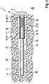
- An in Fig.1 1 illustrated sliding anchor as a rock anchor 1 is a mine anchor used in mining for the temporary securing of tunnels.
- the sliding anchor 1 can absorb tensile forces and thus keep detaching outer rock layers on the tunnel in the mining by initiating these forces in deeper layers. Furthermore, shear forces can be absorbed by the sliding anchor 1 on the rock 18 and thereby an additional securing of the outer rock layers in the tunnel in the mine is possible.
- the sliding anchor 1 comprises an anchor tube 2 made of metal, for. As steel or glass fiber reinforced plastic, as a solid profile without cavity.
- an anchor tube 2 made of metal, for. As steel or glass fiber reinforced plastic, as a solid profile without cavity.
- a Drilled hole 19 in the rock 18 and subsequently a fixation substance 20, z.
- a resin in a cartridge or concrete introduced into the bore 19.
- the sliding anchor 1 is inserted into the bore 19 and thereby the fixing substance 20 is pressed into a space 21 between the sliding anchor 1 and the rock 18.
- a first embodiment of the sliding anchor 1 is shown.
- the sliding anchor 1 is already inserted into the bore 19 on the rock 18 and secured cohesively to the fixing material 20 to the rock 18.
- the anchor tube 2 has a front end 3 on a working space 22 and a rear end 4 in the region of the rear end 4 of the bore 19.
- a cylindrical sleeve 11 is coaxially pushed onto the anchor tube 2.
- a spring 9 formed as a helical spring 10 is arranged as an elastic element 9 made of steel on a sleeve space 12 enclosed by the sleeve 11.
- the support ring 17 is materially connected and non-movably connected to the anchor tube 2 in the direction of a longitudinal axis 6 of the anchor tube 2.
- a plate 15 is integrally formed with the sleeve 11, a plate 15 as a sleeve support member 14.
- the sleeve support member 14 and the plate 15 in this case has an opening and in this opening, the anchor tube 4 is mounted axially displaceable.
- the anchor tube 2 can move relative to the plate 15 and thus also to the sleeve 11.
- the sleeve 11 is materially connected by means of the fixing substance 20 with the rock 18.
- the anchor tube 2 is provided with a sliding coating 5, so that substantially no forces can be transmitted between the anchor tube 2 and the fixation substance 20.
- a damping element 23 for receiving dynamic loads is additionally present.
- the sleeve 11 is closed in the region of a rear end of the sleeve 11 by a closing cap 13.
- the anchor tube 2 is provided in the region of the front end 3 with an external thread shown.
- An anchor plate 8 and an anchor nut 7 is pushed onto the anchor tube 2 at the working space 22, ie outside the bore 19.
- the anchor nut 7 an unillustrated internal thread, which engages in the external thread of the anchor tube 2.
- the anchor plate 8 rests against the rock 18 in the region of the borehole mouth, so that the rock 18 can be secured by applying pressure forces from the anchor plate 8 to the rock 18 and introducing them as tensile forces into the anchor tube 2 with the anchor nut 7 ,
- the tensile forces in the anchor tube 2 are applied with the support ring 17 to the coil spring 10 and of the coil spring 10 on the damping element 23 and of the damping element 23 to the plate 15 and the sleeve support member 14.
- the forces acting on the sleeve support member 14 axial forces in the direction of the longitudinal axis 6 are transmitted to the sleeve 11 and the sleeve 11 by means of the fixing material 20 on the rock 18.
- the spring 9 as an elastic element 9 in addition to another components of the sliding anchor 1, z.
- the force F corresponds to the tensile force acting in the anchor tube 2, which acts as a compressive force on the spring 9.
- the sliding anchor 1 thus has a sliding function and when deformations of the outer rock layers 18 occur, it is possible due to an increase in length of the sliding anchor 1 due to a change in length or a compression of the spring 9 even with larger detachments or deformations of the rock 18 in the anchor plate 8 to avoid breakage or failure of the sliding anchor 1.
- the spring 9 can additionally absorb or dampen dynamic load.
- a second embodiment of the sliding anchor 1 is shown.
- the sleeve 11 is disposed outside the fixation substance 20 in the bore 19 on the rock 18 and the transmission of the absorbed by the anchor tube 2 tensile forces in the rock 18 is performed by the standing in direct contact with the anchor tube 2 fixative 20.
- the anchor nut 7 is not connected to the anchor tube 2, but the sleeve 11 has an unillustrated external thread, which engages in a non-illustrated internal thread of the anchor nut 7.
- a third embodiment of the sliding anchor 1 is shown.
- the sleeve 11 is arranged outside the bore 19 on the working space 22.
- the transmission of the existing in the anchor tube 2 tensile forces in the rock 18 is carried out with a direct contact between the anchor tube 2 and the fixative 20.
- the sliding anchor 1 has no anchor nut 7 and the plate 15 as a sleeve support member 14 rests on the anchor plate 8. In a movement of the outer rock layers or the anchor plate 8 as shown in FIG Fig. 3 to the right, in addition to the anchor plate 8 and the sleeve 11 performs this movement to the right with.
- the anchor tube 2 is due to the fixation with the fixative 20 at lower, fixed Rock strata immutable in the movement, so that in such a movement of the anchor plate 8 as shown in FIG Fig. 3 to the right, the spring 9 compressed (length reduction), ie, a smaller extension in the direction of the longitudinal axis 6, because at the front end 3 of the anchor tube 2 of the support ring 17 and thus the damping element 23 is fixedly connected to the fixed anchor tube 2 and thus the Spring 9 is compressed.
- the sleeve 11 In addition to the anchor tube 2 and the spring 9 is generally also the sleeve 11, the sleeve support member 14 and the Ankerrohrauflagelement 16 made of metal, for. Steel.
- the integrated into the sliding anchor 1 spring 9 as an elastic element 9 can perform large deformations or changes in length and thereby causes a change in length or a sliding function of the sliding anchor 1.
- the spring 9 in addition to static loads and dynamic loads are well received.
- the risk of anchor breakage with the sliding anchor 1 can thereby be substantially reduced and by the use of springs 9 with different spring constants in an otherwise identical sliding anchor 1, the sliding anchor 1 and various applications or types of rock 18 can be well adjusted.
Landscapes
- Engineering & Computer Science (AREA)
- Mining & Mineral Resources (AREA)
- Structural Engineering (AREA)
- Life Sciences & Earth Sciences (AREA)
- General Life Sciences & Earth Sciences (AREA)
- Geochemistry & Mineralogy (AREA)
- Geology (AREA)
- Piles And Underground Anchors (AREA)
Applications Claiming Priority (1)
| Application Number | Priority Date | Filing Date | Title |
|---|---|---|---|
| DE102011005361A DE102011005361A1 (de) | 2011-03-10 | 2011-03-10 | Gleitanker |
Publications (1)
| Publication Number | Publication Date |
|---|---|
| EP2497901A2 true EP2497901A2 (fr) | 2012-09-12 |
Family
ID=45655199
Family Applications (1)
| Application Number | Title | Priority Date | Filing Date |
|---|---|---|---|
| EP12152106A Withdrawn EP2497901A2 (fr) | 2011-03-10 | 2012-01-23 | Ancrage coulissant |
Country Status (5)
| Country | Link |
|---|---|
| US (1) | US20120230774A1 (fr) |
| EP (1) | EP2497901A2 (fr) |
| AU (1) | AU2012200555A1 (fr) |
| CA (1) | CA2764585A1 (fr) |
| DE (1) | DE102011005361A1 (fr) |
Cited By (4)
| Publication number | Priority date | Publication date | Assignee | Title |
|---|---|---|---|---|
| CN102865088A (zh) * | 2012-09-12 | 2013-01-09 | 山东科技大学 | 拉压耦合型高强大变形锚杆及其使用方法 |
| CN104481565A (zh) * | 2014-12-10 | 2015-04-01 | 重庆大学 | 一种压力分散型大变形自适应锚杆 |
| CN112177648A (zh) * | 2020-09-28 | 2021-01-05 | 中国矿业大学 | 一种新型抗剪切大变形吸能锚杆 |
| RU211793U1 (ru) * | 2022-01-13 | 2022-06-22 | Федор Александрович Анисимов | Муфта гибкого анкера |
Families Citing this family (11)
| Publication number | Priority date | Publication date | Assignee | Title |
|---|---|---|---|---|
| CN103016037B (zh) * | 2012-12-28 | 2015-01-07 | 山东大学 | 一种新型预紧力显示让压锚杆弹性圆托盘及其使用方法 |
| WO2016029266A1 (fr) * | 2014-08-28 | 2016-03-03 | Stacey Kevin Frank | Boulon d'ancrage et procédé de stabilisation d'excavations |
| CN104594927B (zh) * | 2014-11-26 | 2017-01-18 | 中国矿业大学 | 锚索 |
| CN105089686A (zh) * | 2015-07-23 | 2015-11-25 | 合肥吉源电子有限公司 | 一种防冲击地压加长锚杆 |
| CN106523008B (zh) * | 2016-12-23 | 2023-07-21 | 山东科技大学 | 锚杆受力测读预警装置及使用方法 |
| ZA201801906B (en) * | 2017-04-18 | 2023-01-25 | Ncm Innovations Pty Ltd | Rock bolt installation tool |
| CN109469055B (zh) * | 2018-12-20 | 2023-09-19 | 长安大学 | 一种局部管缝式端扩型吸能锚杆及其施工方法 |
| CN112343635B (zh) * | 2020-11-04 | 2022-11-01 | 中铁隆昌铁路器材有限公司 | 矿用复合中空树脂锚杆组件及其安装方法 |
| CN114810174B (zh) * | 2022-04-26 | 2025-08-15 | 华能煤炭技术研究有限公司 | 可伸缩锚杆及支护系统 |
| CN116591719B (zh) * | 2023-04-28 | 2026-04-24 | 中铁四局集团有限公司 | 一种隧道吸能让压支护系统及方法 |
| CN117072216A (zh) * | 2023-09-20 | 2023-11-17 | 中国人民解放军军事科学院国防工程研究院工程防护研究所 | 一种位移可恢复抗爆锚杆 |
Citations (1)
| Publication number | Priority date | Publication date | Assignee | Title |
|---|---|---|---|---|
| DE2904778A1 (de) | 1978-02-08 | 1979-08-09 | Ellsworth V Conkle | Einrichtung zur ueberwachung von firstenbewegungen |
Family Cites Families (11)
| Publication number | Priority date | Publication date | Assignee | Title |
|---|---|---|---|---|
| US2725843A (en) * | 1951-06-01 | 1955-12-06 | Francis A E Koski | Sag indicator |
| US3646553A (en) * | 1969-11-26 | 1972-02-29 | Ellsworth V Conkle | Roof micrometer and warning instrument |
| DE2629351C2 (de) * | 1976-06-30 | 1978-05-24 | Bwz Berg- Und Industrietechnik Gmbh, 4250 Bottrop | Vorrichtung zum Setzen eines Klebeankers |
| DE3503012A1 (de) * | 1985-01-30 | 1986-07-31 | Dyckerhoff & Widmann AG, 8000 München | Verspannvorrichtung fuer das zugglied eines ankers, insbesondere eines felsankers |
| DE3538995C2 (de) * | 1985-11-02 | 1994-06-30 | Fischer Artur Werke Gmbh | Korrosionsschutz für einen in einem Sackloch verankerten Spreizdübel |
| AT396390B (de) * | 1987-11-16 | 1993-08-25 | Mayreder Kraus & Co Ing | Gebirgsanker |
| US5535561A (en) * | 1994-08-30 | 1996-07-16 | Schuyler; Peter W. | Cable hold down and bracing system |
| US5882148A (en) * | 1997-02-07 | 1999-03-16 | Dm Technologies Ltd. | Apparatus for yielding support of rock |
| IT1290040B1 (it) * | 1997-03-07 | 1998-10-19 | Marcegaglia S P A | Metodo per la stabilizzazione di ammassi rocciosi e relativo elemento stabilizzatore |
| DE19848176A1 (de) * | 1998-10-20 | 2000-04-27 | Adolf Wuerth Gmbh & Co Kg | Verfahren und Bolzenanker zur Abstandsmontage |
| AUPR198400A0 (en) * | 2000-12-11 | 2001-01-11 | Poldmaa, Arvo | Window link anchor point |
-
2011
- 2011-03-10 DE DE102011005361A patent/DE102011005361A1/de not_active Withdrawn
-
2012
- 2012-01-18 CA CA2764585A patent/CA2764585A1/fr not_active Abandoned
- 2012-01-23 EP EP12152106A patent/EP2497901A2/fr not_active Withdrawn
- 2012-01-31 AU AU2012200555A patent/AU2012200555A1/en not_active Abandoned
- 2012-03-09 US US13/416,411 patent/US20120230774A1/en not_active Abandoned
Patent Citations (1)
| Publication number | Priority date | Publication date | Assignee | Title |
|---|---|---|---|---|
| DE2904778A1 (de) | 1978-02-08 | 1979-08-09 | Ellsworth V Conkle | Einrichtung zur ueberwachung von firstenbewegungen |
Cited By (6)
| Publication number | Priority date | Publication date | Assignee | Title |
|---|---|---|---|---|
| CN102865088A (zh) * | 2012-09-12 | 2013-01-09 | 山东科技大学 | 拉压耦合型高强大变形锚杆及其使用方法 |
| CN102865088B (zh) * | 2012-09-12 | 2015-04-08 | 山东科技大学 | 拉压耦合型高强大变形锚杆及其使用方法 |
| CN104481565A (zh) * | 2014-12-10 | 2015-04-01 | 重庆大学 | 一种压力分散型大变形自适应锚杆 |
| CN112177648A (zh) * | 2020-09-28 | 2021-01-05 | 中国矿业大学 | 一种新型抗剪切大变形吸能锚杆 |
| CN112177648B (zh) * | 2020-09-28 | 2021-05-25 | 中国矿业大学 | 一种新型抗剪切大变形吸能锚杆 |
| RU211793U1 (ru) * | 2022-01-13 | 2022-06-22 | Федор Александрович Анисимов | Муфта гибкого анкера |
Also Published As
| Publication number | Publication date |
|---|---|
| DE102011005361A1 (de) | 2012-09-13 |
| AU2012200555A1 (en) | 2012-09-27 |
| CA2764585A1 (fr) | 2012-09-10 |
| US20120230774A1 (en) | 2012-09-13 |
Similar Documents
| Publication | Publication Date | Title |
|---|---|---|
| EP2497901A2 (fr) | Ancrage coulissant | |
| DE102010063098A1 (de) | Gesteinsanker | |
| DE102011005855A1 (de) | Gesteinsanker | |
| DE112008002251T5 (de) | Gesteinsbolzen mit mechanischem Anker | |
| DE2635083A1 (de) | Dichtungsanordnung und stroemungssteuerung dafuer | |
| EP2195549B1 (fr) | Maître-cylindre, notamment pour l'actionnement d'un frein ou d'un embrayage d'un véhicule à moteur | |
| DE3047709C2 (de) | Gebirgsanker | |
| DE102013002734A1 (de) | Ankerkopf für einen Zuganker | |
| WO2011157850A2 (fr) | Tirant d'ancrage amélioré en plastique renforcé par fibres | |
| EP1828487A1 (fr) | Procede pour installer des boulons d'ancrage et boulon d'ancrage utilisable avec ledit procede | |
| EP2487328A2 (fr) | Ancre pour la roche | |
| DE102010002214A1 (de) | Bewehrungs- und/oder Ankerschraube | |
| DE102011076592A1 (de) | Gesteinsanker | |
| DE102012203696A1 (de) | Gesteinsanker | |
| AT400471B (de) | Hydraulischer selbstbohr-gesteinanker | |
| DE102005000158A1 (de) | Bohr- und Ankersetzgerät mit integrierter Auspressvorrichtung | |
| DE102012107752A1 (de) | Zweistufiger Teleskopzylinder mit Rückzugfeder | |
| DE102006011652B4 (de) | Zweischritt-Hohlstabverbundanker für Kleberpatronen und Klebergranulat | |
| DE4438997B4 (de) | Gebirgsanker | |
| DE102018106157A1 (de) | Vorrichtung zum Abdämpfen von Druckkräften | |
| EP2543816A2 (fr) | Boulon d'ancrage de roche | |
| WO2013174681A1 (fr) | Tirant d'ancrage à une roche | |
| DE3138610C2 (de) | Einrichtung zur haltbaren Befestigung von Gegenständen in Bohrlöchern | |
| DE3741066C1 (en) | Flexible material-displacing holding device for a rock anchor | |
| DE102020125370A1 (de) | Vorrichtung zum Befüllen von Bohrlöchern mit kleinem Durchmesser mit Injektionsmaterial zwecks Einbringung und Befestigung von Ankern |
Legal Events
| Date | Code | Title | Description |
|---|---|---|---|
| PUAI | Public reference made under article 153(3) epc to a published international application that has entered the european phase |
Free format text: ORIGINAL CODE: 0009012 |
|
| AK | Designated contracting states |
Kind code of ref document: A2 Designated state(s): AL AT BE BG CH CY CZ DE DK EE ES FI FR GB GR HR HU IE IS IT LI LT LU LV MC MK MT NL NO PL PT RO RS SE SI SK SM TR |
|
| AX | Request for extension of the european patent |
Extension state: BA ME |
|
| STAA | Information on the status of an ep patent application or granted ep patent |
Free format text: STATUS: THE APPLICATION IS DEEMED TO BE WITHDRAWN |
|
| 18D | Application deemed to be withdrawn |
Effective date: 20140801 |