EP2498251B1 - Signalverarbeitungsverfahren, informationsprozessor und signalverarbeitungsprogramm - Google Patents
Signalverarbeitungsverfahren, informationsprozessor und signalverarbeitungsprogramm Download PDFInfo
- Publication number
- EP2498251B1 EP2498251B1 EP10828387.0A EP10828387A EP2498251B1 EP 2498251 B1 EP2498251 B1 EP 2498251B1 EP 10828387 A EP10828387 A EP 10828387A EP 2498251 B1 EP2498251 B1 EP 2498251B1
- Authority
- EP
- European Patent Office
- Prior art keywords
- noise
- noise information
- signal
- information
- unit
- Prior art date
- Legal status (The legal status is an assumption and is not a legal conclusion. Google has not performed a legal analysis and makes no representation as to the accuracy of the status listed.)
- Active
Links
Images




Classifications
-
- G—PHYSICS
- G10—MUSICAL INSTRUMENTS; ACOUSTICS
- G10L—SPEECH ANALYSIS TECHNIQUES OR SPEECH SYNTHESIS; SPEECH RECOGNITION; SPEECH OR VOICE PROCESSING TECHNIQUES; SPEECH OR AUDIO CODING OR DECODING
- G10L21/00—Speech or voice signal processing techniques to produce another audible or non-audible signal, e.g. visual or tactile, in order to modify its quality or its intelligibility
- G10L21/02—Speech enhancement, e.g. noise reduction or echo cancellation
- G10L21/0208—Noise filtering
Definitions
- the present invention relates to a signal processing technique of suppressing noise in a noisy signal to enhance a target signal.
- a noise suppressing technology is known as a signal processing technology of partially or completely suppressing noise in a noisy signal (a signal containing a mixture of noise and a target signal) and outputting an enhanced signal (a signal obtained by enhancing the target signal).
- a noise suppressor is a system that suppresses noise mixed in a target audio signal.
- the noise suppressor is used in various audio terminals such as mobile phones.
- patent literature 1 discloses a method of suppressing noise by multiplying an input signal by a spectral gain smaller than 1.
- Patent literature 2 discloses a method of suppressing noise by directly subtracting estimated noise from a noisy signal.
- patent literatures 1 and 2 need to estimate noise from the target signal that has already become noisy due to the mixed noise. However, there are limitations on accurately estimating noise only from the noisy signal. Hence, the methods described in patent literatures 1 and 2 are effective only when the noise is much smaller than the target signal. If the condition that the noise is much smaller than the target signal is not satisfied, the noise estimate accuracy is poor. For this reason, the methods described in patent literatures 1 and 2 can achieve no sufficient noise suppression effect, and the enhanced signal includes a larger distortion.
- patent literature 3 discloses a noise suppressing system capable of implementing a sufficient noise suppression effect and a smaller distortion in the enhanced signal even if the condition that the noise is much smaller than the target signal is not satisfied. Assuming that the characteristics of noise to be mixed into the target signal are known in advance to a certain extent, the method described in patent literature 3 subtracts previously recorded noise information (information about the noise characteristics) from the noisy signal, thereby suppressing the noise. Patent literature 3 also discloses a method of, if an input signal power obtained by analyzing an input signal is large, integrating a large coefficient into noise information, or if the input signal power is small, integrating a small coefficient, and subtracting the integration result from the noisy signal.
- US 4,630,304 A relates to an automatic background noise estimator for a noise suppression system for generating an estimate of the background noise power spectral density provided to the noise suppressor.
- the present invention has been made in consideration of the above-described situation, and has as its exemplary object to provide a signal processing technique of solving the above-described problems.
- a signal processing method includes, when suppressing a noise in a degraded signal, generating noise information depending on a noise suppression result of the degraded signal and, suppressing the noise in the degraded signal using the generated noise information.
- an information processing apparatus includes a noise suppressor that suppresses a noise in a degraded signal and, a noise information generation unit that generates noise information based on a result of suppression of the noise in the degraded signal, wherein the noise suppressor suppresses the noise in the degraded signal using the noise information.
- a signal processing program stored in a computer readable non-transitory medium causes a computer to execute a process of generating noise information based on a result of a process of suppressing a noise and, a process of suppressing a noise in a degraded signal using the generated noise information.
- the present invention it is possible to provide a signal processing technique of suppressing various kinds of noise including unknown noise without storing a number of pieces of noise information in advance.
- a noise suppressing apparatus which partially or completely suppresses noise in a noisy signal (a signal containing a mixture of noise and a target signal) and outputs an enhanced signal (a signal obtained by enhancing the target signal).
- Fig. 1 is a block diagram showing the overall arrangement of a noise suppressing apparatus 100.
- the noise suppressing apparatus 100 functions as part of a device such as a digital camera, a notebook computer, or a mobile phone.
- the exemplary embodiment is not limited to this and is also applicable to an information processing apparatus of any type that requires noise removal from an input signal.
- Fig. 8 is a block diagram showing an example of an arrangement of an information processing apparatus 1200 according to the exemplary embodiment.
- the information processing apparatus 1200 includes a noise suppression unit 3 and a noise information generation unit 7.
- the degraded signal (signal in which target signal and noise are mixed) is inputted to an input terminal 1 as a sample value sequence.
- An FFT unit 2 performs transform such as Fourier transform of the noisy signal supplied to the input terminal 1, thereby dividing the signal into a plurality of frequency components.
- the noise suppression unit 3 receives the magnitude spectrum out of the plurality of frequency components, whereas an IFFT unit 4 is provided with the phase spectrum. Note that the magnitude spectrum is supplied to the noise suppression unit 3 in this case.
- the exemplary embodiment is not limited to this, and a power spectrum corresponding to the square of the magnitude spectrum may be supplied to the noise suppression unit 3.
- a temporary memory 6 includes a memory element such as a semiconductor memory and stores noise information (information about noise characteristics).
- the temporary memory 6 stores noise spectrum forms as the noise information.
- the temporary memory 6 can also store, for example, the frequency characteristics of phases and features such as the intensities and time-rate changes for a specific frequency in place of or together with the spectra.
- the noise information can also include statistics (maxima, minima, variances, and medians) and the like.
- the noise suppression unit 3 suppresses a noise at each frequency using the degraded signal magnitude spectrum supplied by the FFT unit 2 and the noise information supplied by the temporary memory 6, and provides the IFFT unit 4 with an enhanced signal magnitude spectrum as a noise suppression result.
- the IFFT unit 4 inversely transforms the combination of the enhanced signal magnitude spectrum supplied from the noise suppression unit 3 and the degraded signal phase supplied from the FFT unit 2, and supplies an enhanced signal sample to an output terminal 5.
- the noise information generation unit 7 is also simultaneously provided with the enhanced signal magnitude spectrum as the noise suppression result.
- the noise information generation unit 7 generates new noise information based on the enhanced signal magnitude spectrum as the noise suppression result and supplies the new noise information to the temporary memory 6.
- the temporary memory 6 adapts current noise information using the new noise information supplied from the noise information generation unit 7.
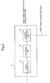
- Fig. 2 is a block diagram showing the arrangement of the FFT unit 2.
- the FFT unit 2 includes a frame dividing unit 21, a windowing unit 22, and a Fourier transform unit 23.
- the frame dividing unit 21 receives the noisy signal sample and divides it into frames corresponding to K/2 samples, where K is an even number.
- the noisy signal sample divided into frames is supplied to the windowing unit 22 and multiplied by a window function w(t).
- a symmetric window function is used for a real signal.
- the windowing unit 22 may use various window functions such as a hamming window, a Kaiser window, and a Blackman window.
- the windowed output is supplied to the Fourier transform unit 23 and transformed into a noisy signal spectrum Yn(k).
- the noisy signal spectrum Yn(k) is separated into the phase and the magnitude.
- a noisy signal phase spectrum argYn(k) is supplied to the IFFT unit 4, whereas a noisy signal magnitude spectrum
- the FFT unit 2 can use the power spectrum instead of the magnitude spectrum.
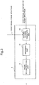
- Fig. 3 is a block diagram showing the arrangement of the IFFT unit 4.
- the IFFT unit 4 includes an inverse Fourier transform unit 43, a windowing unit 42, and a frame reconstruction unit 41.
- the inverse Fourier transform unit 43 inversely Fourier-transforms the resultant enhanced signal.
- the frame reconstruction unit 41 provides the output terminal 5 with the resultant output signal.
- the transform in the FFT unit 2 and the IFFT unit 4 in Figs. 2 and 3 has been described above as Fourier transform.
- the FFT unit 2 and the IFFT unit 4 can use any other transform such as cosine transform, modified discrete cosine transform (MDCT), Hadamard transform, Haar transform, or Wavelet transform in place of the Fourier transform.
- cosine transform or modified cosine transform obtains only a magnitude as a transform result. This obviates the necessity for the path from the FFT unit 2 to the IFFT unit 4 in Fig. 1 .
- the noise information recorded in the temporary memory 6 needs to include only magnitudes (or powers), contributing to reduction of the memory size and the number of computations of a noise suppressing process.
- Haar transform allows to omit multiplication and reduce the area of an LSI chip. Since Wavelet transform can change the time resolution depending on the frequency, better noise suppression is expected.
- the noise suppression unit 3 may perform actual suppression.
- the FFT unit 2 can achieve high sound quality by integrating more frequency components from the low frequency range where the discrimination capability of hearing characteristics is high to the high frequency range with a poorer capability.
- noise suppression is executed after integrating a plurality of frequency components, the number of frequency components to which noise suppression is applied decreases. The noise suppressing apparatus 100 can thus decrease the whole number of computations.
- the noise suppression unit 3 can perform various kinds of suppression. Typical suppressing methods are the SS (Spectrum Subtraction) method and the MMSE STSA (Minimum Mean-Square Error Short-Time Spectral Amplitude Estimator) method.
- the noise suppression unit 3 subtracts the noise information supplied by the temporary memory 6 from the degraded signal magnitude spectrum supplied by the FFT unit 2.
- the noise suppression unit 3 calculates a suppression coefficient for each of the plurality of frequency components using the noise information supplied by the temporary memory 6 and the degraded signal magnitude spectrum supplied by the FFT unit 2.
- the noise suppression unit 3 multiplies the degraded signal magnitude spectrum by the suppression coefficient.
- the suppression coefficient is determined so as to minimize the mean square power of the enhanced signal.
- the noise suppression unit 3 can apply flooring to avoid excessive noise suppression.
- Flooring is a method of avoiding suppression beyond the maximum suppression amount.
- a flooring parameter determines the maximum suppression amount.
- the noise suppression unit 3 imposes restrictions so the result obtained by subtracting the modified noise information from the noisy signal magnitude spectrum is not smaller than the flooring parameter. More specifically, if the subtraction result is smaller than the flooring parameter, the noise suppression unit 3 replaces the subtraction result with the flooring parameter.
- the noise suppression unit 3 replaces the spectral gain with the flooring parameter. Details of the flooring are disclosed in literature " M. Berouti, R. Schwartz, and J.
- the noise suppression unit 3 can also set the number of frequency components of the noise information to be smaller than the number of frequency components of the noisy signal spectrum. At this time, a plurality of frequency components share a plurality of pieces of noise information.
- the frequency resolution of the noisy signal spectrum is higher than in a case in which the plurality of frequency components are integrated for both the noisy signal spectrum and the noise information. For this reason, the noise suppression unit 3 can achieve high sound quality by calculation in an amount smaller than in case of the absence of frequency component integration.
- Japanese Patent Laid-Open No. 2008-203879 discloses details of suppression using noise information whose number of frequency components is smaller than the number of frequency components of the noisy signal spectrum.
- the enhanced signal magnitude spectrum as the noise suppression result is supplied to the noise information generation unit 7.
- the noise information generation unit 7 generates new noise information using the noise suppression result and, adapts the noise information stored in the temporary memory 6 using the new noise information. For example, a flat-shaped signal spectrum is prepared as a default value of the noise information stored in the temporary memory 6.
- the noise information generation unit 7 generates the new noise information depending on the noise suppression result in which the signal spectrum is used as the noise information.
- the noise information generation unit 7 adapts the noise information, stored in the temporary memory 6, which is already used for suppression.
- the noise information generation unit 7 When generating the new noise information using the noise suppression result fed back to the noise information generation unit 7, the noise information generation unit 7 generates the noise information such that the larger the noise suppression result at a timing without target signal input is (the larger the noise remaining without being suppressed is), the larger the noise information is.
- the large noise suppression result at the timing without target signal input indicates insufficient suppression. For this reason, the noise information is preferably made larger.
- the noise information is large, the subtraction value of the SS method is large, and the noise suppression result thus becomes small.
- the signal-to-noise ratio (SNR) estimate to be used to calculate the suppression coefficient is small, and therefore, a small suppression coefficient can be obtained. This leads to more intensive noise suppression.
- a plurality of methods are available to generate the new noise information.
- a re-calculation algorithm and a recursive adaptation algorithm will be described as examples.
- the noise information generation unit 7 can recalculate or recursively adapt the noise information, for example, when the magnitude or power of the degraded signal is small so as to completely suppress noise. This is because the power of the signal other than the noise to be suppressed is small at high probability when the magnitude or power of the degraded signal is small.
- the noise information generation unit 7 can detect the small magnitude or power of the degraded signal using the fact that power or an absolute value of the magnitude of the degraded signal is smaller than a threshold.
- the noise information generation unit 7 can also detect the small magnitude or power of the degraded signal using the fact that the difference between the magnitude or power of the degraded signal and the noise information recorded in the temporary memory 6 is smaller than a threshold. That is, the noise information generation unit 7 uses the fact that when the magnitude or power of the degraded signal is similar to the noise information, the noise information makes up a large part of the degraded signal (the SNR is low). Especially, the noise information generation unit 7 can compare the spectral envelopes using a combination of information at a plurality of frequency points, thereby raising the detection accuracy.
- the noise information in the SS method is recalculated so as to equal the degraded signal magnitude spectrum for each frequency at the timing without target signal input.
- the noise information generation unit 7 makes the degraded signal magnitude spectrum
- supplied from the FFT unit 2 when only noise has been input match noise information vn(k). That is, the noise information generation unit 7 calculates the noise information vn(k) by using ⁇ ⁇ n k Yn k where n is the frame number, and k is the frequency number.
- the noise information generation unit 7 may use an average of the noise information vn(k) instead of directly using the noise information vn(k).
- the average may be an average (a moving average using a slide window) based on an FIR filter or an average (leaky integration) based on an IIR filter.
- recursive adaptation of the noise information in the SS method is done by gradually adapting the noise information such that the enhanced signal magnitude spectrum at the timing without target signal input approaches zero for each frequency.
- the noise information generation unit 7 can implement accurate noise suppression in real time by immediately adapting the noise information.
- the noise information generation unit 7 may use any other adaptive algorithm (recursive adaptation algorithm).
- the noise information generation unit 7 recursively adapts the noise information.
- the noise information generation unit 7 adapts the noise information vn (k) for each frequency by the same methods as those described using equations (9) to (11).
- the noise information generation unit 7 may change the adaptation method so as to, for example, first use the re-calculation algorithm and then use the recursive adaptation algorithm.
- the noise information generation unit 7 may change the adaptation method on condition that the noise information has sufficiently approached the optimum value.
- the noise information generation unit 7 may change the adaptation method when, for example, a predetermined time has elapsed. Otherwise, the noise information generation unit 7 may change the adaptation method when the modification amount of the noise information has fallen below a predetermined threshold.
- the noise suppressing apparatus 100 of the exemplary embodiment generates, based on the noise suppression result, the noise information to be used for the noise suppression. It is therefore possible to suppress various kinds of noises including an unknown noise without storing a number of pieces of noise information in advance.
- the noise information generation unit 7 of the second exemplary embodiment generates noise information by multiplying basic information permanently stored in a non-volatile memory, or the like, by a scaling factor. For example, arbitrary information like a flat-shaped signal spectrum is prepared as the basic information (default value) of the noise information.
- the noise information generation unit 7 generates the noise information by multiplying the basic information by the scaling factor and, after that, adapts the noise information and the scaling factor thereof depending on a noise suppression result using the noise information.
- the adaptation of the noise information is described in the first exemplary embodiment in detail. Adaptation of the scaling factor is therefore described here.
- the noise information generation unit 7 When generating the scaling factor using the noise suppression result, the noise information generation unit 7 generates the scaling factor such that the larger the noise suppression result at a timing without target signal input is (the larger the noise remaining without being suppressed is), the larger the noise information is.
- the large noise suppression result at the timing without target signal input indicates insufficient suppression. For this reason, the noise information is preferably made larger by changing the scaling factor.
- a plurality of methods are available to adapt the scaling factor. A re-calculation algorithm and a recursive adaptation algorithm will be described as examples.
- the noise information generation unit 7 can recalculate or recursively adapt the scaling factor, for example, when the magnitude or power of the degraded signal is small so as to completely suppress noise. This is because the power of the signal other than the noise to be suppressed is small at high probability when the magnitude or power of the degraded signal is small.
- the noise information generation unit 7 can detect the small magnitude or power of the degraded signal using the fact that power or an absolute value of the magnitude of the degraded signal is smaller than a threshold.
- the noise information generation unit 7 can also detect the small magnitude or power of the degraded signal using the fact that the difference between the magnitude or power of the degraded signal and the noise information recorded in the temporary memory 6 is smaller than a threshold. That is, the noise information generation unit 7 uses the fact that when the magnitude or power of the degraded signal is similar to the noise information, the noise makes up a large part of the degraded signal (the SNR is low). Especially, the noise information generation unit 7 can compare the spectral envelopes using a combination of information at a plurality of frequency points, thereby raising the detection accuracy.
- the scaling factor in the SS method is recalculated so that the noise information equals the degraded signal magnitude spectrum for each frequency at the timing without target signal input.
- the noise information generation unit 7 obtains the scaling factor ⁇ n(k) so that the degraded signal magnitude spectrum
- supplied from the FFT unit 2 when only noise has been input matches the product of the scaling factor an and the basic information vn(k). That is, the scaling factor ⁇ n(k) is calculated by using ⁇ ⁇ n k Yn k / ⁇ k where n is the frame number, and k is the frequency number.
- recursive adaptation of the scaling factor in the SS method is done by gradually adapting the scaling factor such that the enhanced signal magnitude spectrum at the timing without target signal input approaches zero for each frequency.
- the noise information generation unit 7 can implement accurate noise suppression in real time by immediately adapting the scaling factor.
- the noise information generation unit 7 may use the LS (Least Squares) algorithm or any other adaptive algorithm.
- the noise information generation unit 7 can also immediately apply the generated scaling factor.
- the implementor of the noise suppressing apparatus 100 may design the modification unit 7 to adapt the scaling factor in real time by modifying equations (15) to (17) with reference to the change from equation (13) to equation (14).
- the noise information generation unit 7 recursively adapts the scaling factor.
- the noise information generation unit 7 adapts the scaling factor ⁇ n(k) for each frequency by the same methods as those described using equations (13) to (17).
- the noise information generation unit 7 may change the adaptation method so as to, for example, first use the re-calculation algorithm and then use the recursive adaptation algorithm.
- the noise information generation unit 7 may change the adaptation method on condition that the scaling factor has sufficiently approached the optimum value.
- the modification unit 7 may change the adaptation method when, for example, a predetermined time has elapsed. Otherwise, the noise information generation unit 7 may change the adaptation method when the modification amount of the scaling factor has fallen below a predetermined threshold.
- the arrangements and operations other than the generation method of the noise information in the noise information generation unit 7 are the same as in the first exemplary embodiment, and the description thereof will not be repeated.
- the noise information generation unit 7 may adapt the noise information for large change and adapt the scaling information for small change. Particularly, in a process of generating the noise information from a default value, fast generation of the noise information is possible by adapting the noise information. When the noise information approaches the right value and an error decreases, accurate output of the noise information generation unit may be obtained by adapting the scaling information.
- the noise information generation unit in addition to the effect of the first exemplary embodiment, it is possible to quickly follow the change of the noise characteristics and to obtain accurate output of the noise information generation unit by optionally combine adaptation of the noise information and adaptation of the scaling information.
- a noise suppressing apparatus 200 includes an input terminal 9 in addition to the arrangement of the first exemplary embodiment.
- a noise suppression unit 53 and a noise information generation unit 47 receive, from the input terminal 9, information (noise existence information) representing whether a specific noise exists in the inputted degraded signal. Thereby, the noise suppressing apparatus 200 can make it possible to reliably suppress a noise at a timing the specific noise exists and simultaneously generate the noise information.
- the remaining arrangements and operations are the same as in the first exemplary embodiment, and a detailed description thereof will not be repeated.
- the noise suppressing apparatus 200 of the exemplary embodiment does not generate the noise information at a timing a specific noise does not exist. Hence, a higher noise suppression accuracy can be obtained for the specific noise.
- a noise suppressing apparatus 300 of the exemplary embodiment includes a target signal detecting unit 51.
- An FFT unit 2 provides the target signal detecting unit 51 with a degraded signal magnitude spectrum.
- the target signal detecting unit 51 determines whether the target signal exists or the degree of existence in the degraded signal magnitude spectrum.
- a noise information generation unit 57 Based on the determination result from the target signal detecting unit 51, a noise information generation unit 57 generates noise information. For example, without the target signal, the degraded signal includes only noise, and the suppression result of a noise suppression unit 3 has to be zero. Hence, the noise information generation unit 57 adjusts the noise information described in the first exemplary embodiment and the scaling factor described in the second exemplary embodiment so as to obtain zero as the noise suppression result at this time.
- the noise information generation unit 57 when the degraded signal includes the target signal, the noise information generation unit 57 generates the noise information in accordance with the existence ratio of the target signal. For example, if the ratio of the target signal existing in the degraded signal is 10%, the noise information generation unit 57 adapts the noise information stored in a temporary memory 6 partially (only 90%).
- the noise suppressing apparatus 300 of the exemplary embodiment generates the noise information in accordance with the ratio of noise in the degraded signal. This allows to obtain a more accurate noise suppression result.
- FIG. 6 is a block diagram showing an information processing apparatus 500 including a noise suppressing apparatus 400 described in the first exemplary embodiment.
- the information processing apparatus 500 includes a mechanical unit 91 serving as a noise source, and a mechanical control unit 92 that controls the mechanical unit 91.
- the noise suppressing apparatus 400 is provided with the operation information. This allows the noise suppressing apparatus 400 to reliably operate to generate noise information during the operation of the mechanical unit 91.
- the mechanical control unit 92 may operate the mechanical unit 91 based on an instruction from the noise suppressing apparatus 400 to generate noise, and simultaneously, a noise information generation unit 67 in the noise suppressing apparatus 400 may generate noise information using a degraded signal including the noise.
- the first to fifth exemplary embodiments have been described above concerning noise suppressing apparatuses having different characteristic features.
- Exemplary embodiments also incorporate noise suppressing apparatuses formed by combining the characteristic features in whatever way.
- the present invention may be applied to a system including a plurality of devices or a single apparatus.
- the present invention is also applicable when the signal processing program of software for implementing the functions of the exemplary embodiments to the system or apparatus directly or from a remote site.
- the present invention also incorporates a program that is installed in a computer to cause the computer to implement the functions of the present invention, a medium that stores the program, and a WWW server from which the program is downloaded.
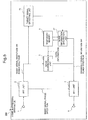
- Fig. 7 is a block diagram of a computer 1000 that executes a signal processing program configured as the first to fifth exemplary embodiments.
- the computer 1000 includes an input unit 1001, a CPU 1002, an output unit 1003, a memory 1004, an external memory 1005, a communication control unit 1006, and a bus 1007 connecting those.
- the CPU 1002 controls the operation of the computer 1000 by reading out the signal processing program. More specifically, upon executing the signal processing program, the CPU 1002 suppresses a noise in the degraded signal and, generates noise information based on the noise suppression result (S801). Next, the CPU 1002 suppresses the noise in the degraded signal using the generated noise information (S802). If a deactivate event has not been generated (S804), the CPU 1002 adapt the noise information using the noise suppression result (S803). That is, the CPU 1002 repeatedly executes noise information generation/adaptation and noise suppression until the deactivate event is inputted. Various deactivate events are assumed, including power-off and microphone-off.
- the computer as described above makes it possible to obtain the same effects as in the first to seventh exemplary embodiments.
Landscapes
- Engineering & Computer Science (AREA)
- Computational Linguistics (AREA)
- Quality & Reliability (AREA)
- Signal Processing (AREA)
- Health & Medical Sciences (AREA)
- Audiology, Speech & Language Pathology (AREA)
- Human Computer Interaction (AREA)
- Physics & Mathematics (AREA)
- Acoustics & Sound (AREA)
- Multimedia (AREA)
- Noise Elimination (AREA)
- Soundproofing, Sound Blocking, And Sound Damping (AREA)
Claims (8)
- Audiosignalverarbeitungsverfahren zum Unterdrücken von Rauschen in einem degradierten Audiosignal, das aufweist:rekursives Anpassen von Rauschinformationen mittels eines Perturbationsverfahrens; undUnterdrücken des Rauschens im degradierten Audiosignal mittels der Rauschinformationen,wobei die rekursive Anpassung der Rauschinformationen mittels einer der folgenden Gleichungen durchgeführt wird:


- Signalverarbeitungsverfahren nach Anspruch 1, wobei die Rauschinformationen durch Multiplizieren von Basisinformationen mit einem Skalierungsfaktor erzeugt werden.
- Signalverarbeitungsverfahren nach Anspruch 1 oder 2, wobei Informationen, die repräsentieren, ob Rauschen im degradierten Signal vorhanden ist, eingegeben werden, und die Rauschinformationen erzeugt werden, wenn das Rauschen im degradierten Signal vorhanden ist.
- Signalverarbeitungsverfahren nach einem der Ansprüche 1 bis 3, wobei ein Grad des Vorhandenseins eines Zielsignals im degradierten Signal durch Analysieren des degradierten Signals bestimmt wird und die Rauschinformationen beruhend auf einem Bestimmungsergebnis erzeugt werden.
- Informationsverarbeitungsvorrichtung zum Unterdrücken von Rauschen in einem degradierten Audiosignal, die aufweist:einen Rauschunterdrücker (3, 53), der konfiguriert ist, Rauschen im degradierten Audiosignal zu unterdrücken;eine Rauschinformations-Erzeugungseinheit (7, 47, 57, 67), die konfiguriert ist, Rauschinformationen mittels eines Perturbationsverfahrens rekursiv anzupassen,wobei der Rauschunterdrücker (3, 53) konfiguriert ist, das Rauschen im degradierten Audiosignal mittels der Rauschinformationen zu unterdrücken,wobei die Rauschinformations-Erzeugungseinheit (7, 47, 57, 67) konfiguriert ist, die Rauschinformationen mittels einer der folgenden Gleichungen rekursiv anzupassen:


- Informationsverarbeitungsvorrichtung nach Anspruch 5, die ferner eine Speichereinheit (6) aufweist, die konfiguriert ist, die durch die Rauschinformations-Erzeugungseinheit erzeugten Rauschinformationen zu speichern.
- Informationsverarbeitungsvorrichtung nach Anspruch 5 oder 6, die ferner aufweist:eine mechanische Einheit, die konfiguriert ist als eine Rauschquelle zu dienen; undeine mechanische Steuereinheit, die konfiguriert ist, die mechanische Einheit zu steuern,wobei die Rauschinformations-Erzeugungseinheit konfiguriert ist, die Rauschinformationen zu einem Zeitpunkt zu erzeugen, zu dem die mechanische Steuereinheit das Rauschen durch Betreiben der mechanischen Einheit erzeugt.
- Computerlesbares Medium zum Speichern eines Signalverarbeitungsprogramms, das einen Computer veranlasst, die Schritte des Signalverarbeitungsverfahrens nach einem der Ansprüche 1 bis 4 auszuführen.
Applications Claiming Priority (2)
| Application Number | Priority Date | Filing Date | Title |
|---|---|---|---|
| JP2009255419A JP2011100029A (ja) | 2009-11-06 | 2009-11-06 | 信号処理方法、情報処理装置、及び信号処理プログラム |
| PCT/JP2010/069869 WO2011055829A1 (ja) | 2009-11-06 | 2010-11-02 | 信号処理方法、情報処理装置、及び信号処理プログラム |
Publications (3)
| Publication Number | Publication Date |
|---|---|
| EP2498251A1 EP2498251A1 (de) | 2012-09-12 |
| EP2498251A4 EP2498251A4 (de) | 2013-08-07 |
| EP2498251B1 true EP2498251B1 (de) | 2019-12-25 |
Family
ID=43970061
Family Applications (1)
| Application Number | Title | Priority Date | Filing Date |
|---|---|---|---|
| EP10828387.0A Active EP2498251B1 (de) | 2009-11-06 | 2010-11-02 | Signalverarbeitungsverfahren, informationsprozessor und signalverarbeitungsprogramm |
Country Status (5)
| Country | Link |
|---|---|
| US (1) | US9190070B2 (de) |
| EP (1) | EP2498251B1 (de) |
| JP (1) | JP2011100029A (de) |
| CN (1) | CN102598127B (de) |
| WO (1) | WO2011055829A1 (de) |
Families Citing this family (3)
| Publication number | Priority date | Publication date | Assignee | Title |
|---|---|---|---|---|
| FR3034625A1 (fr) | 2015-04-10 | 2016-10-14 | Naturex | Solvant eutectique d'extraction, procede d'extraction par eutectigenese utilisant ledit solvant, et extrait issu dudit procede d'extraction. |
| CN107045872B (zh) * | 2016-02-05 | 2020-09-01 | 中国电信股份有限公司 | 通话回声的识别方法和装置 |
| CN106910511B (zh) * | 2016-06-28 | 2020-08-14 | 阿里巴巴集团控股有限公司 | 一种语音去噪方法和装置 |
Family Cites Families (28)
| Publication number | Priority date | Publication date | Assignee | Title |
|---|---|---|---|---|
| US4630304A (en) * | 1985-07-01 | 1986-12-16 | Motorola, Inc. | Automatic background noise estimator for a noise suppression system |
| JPH05316186A (ja) * | 1992-05-08 | 1993-11-26 | Matsushita Electric Ind Co Ltd | 音声認識電話機 |
| ZA95599B (en) * | 1994-02-28 | 1996-02-06 | Qualcomm Inc | Doubletalk detection by means of spectral content |
| JP3484757B2 (ja) * | 1994-05-13 | 2004-01-06 | ソニー株式会社 | 音声信号の雑音低減方法及び雑音区間検出方法 |
| JP3451146B2 (ja) | 1995-02-17 | 2003-09-29 | 株式会社日立製作所 | スペクトルサブトラクションを用いた雑音除去システムおよび方法 |
| US6001131A (en) * | 1995-02-24 | 1999-12-14 | Nynex Science & Technology, Inc. | Automatic target noise cancellation for speech enhancement |
| JPH09212196A (ja) * | 1996-01-31 | 1997-08-15 | Nippon Telegr & Teleph Corp <Ntt> | 雑音抑圧装置 |
| US6570985B1 (en) * | 1998-01-09 | 2003-05-27 | Ericsson Inc. | Echo canceler adaptive filter optimization |
| US6850783B1 (en) * | 1998-08-07 | 2005-02-01 | Ericsson Inc. | Methods and apparatus for mitigating the effects of microphone overload in echo cancelation systems |
| US6606382B2 (en) * | 2000-01-27 | 2003-08-12 | Qualcomm Incorporated | System and method for implementation of an echo canceller |
| JP2001215990A (ja) * | 2000-01-31 | 2001-08-10 | Japan Science & Technology Corp | ロボット聴覚装置 |
| US6859531B1 (en) * | 2000-09-15 | 2005-02-22 | Intel Corporation | Residual echo estimation for echo cancellation |
| JP4282227B2 (ja) | 2000-12-28 | 2009-06-17 | 日本電気株式会社 | ノイズ除去の方法及び装置 |
| DE60142800D1 (de) * | 2001-03-28 | 2010-09-23 | Mitsubishi Electric Corp | Rauschunterdrücker |
| JP4088148B2 (ja) * | 2002-12-27 | 2008-05-21 | 松下電器産業株式会社 | 雑音抑圧装置 |
| US6947549B2 (en) * | 2003-02-19 | 2005-09-20 | The Hong Kong Polytechnic University | Echo canceller |
| JP4876378B2 (ja) * | 2004-08-27 | 2012-02-15 | 日本電気株式会社 | 音声処理装置、音声処理方法及び音声処理プログラム |
| CN101053161B (zh) * | 2004-11-02 | 2010-09-08 | 松下电器产业株式会社 | 噪声抑制装置 |
| US8761385B2 (en) * | 2004-11-08 | 2014-06-24 | Nec Corporation | Signal processing method, signal processing device, and signal processing program |
| EP1845520A4 (de) * | 2005-02-02 | 2011-08-10 | Fujitsu Ltd | Signalverarbeitungsverfahren und signalverarbeitungseinrichtung |
| JP2006279185A (ja) | 2005-03-28 | 2006-10-12 | Casio Comput Co Ltd | 撮像装置、音声記録方法及びプログラム |
| JP4639907B2 (ja) * | 2005-03-31 | 2011-02-23 | カシオ計算機株式会社 | 撮像装置、音声記録方法及びプログラム |
| JP4172530B2 (ja) | 2005-09-02 | 2008-10-29 | 日本電気株式会社 | 雑音抑圧の方法及び装置並びにコンピュータプログラム |
| JP2007116585A (ja) * | 2005-10-24 | 2007-05-10 | Matsushita Electric Ind Co Ltd | ノイズキャンセル装置およびノイズキャンセル方法 |
| JP4973873B2 (ja) | 2005-11-15 | 2012-07-11 | 日本電気株式会社 | 残響抑圧の方法、装置及び残響抑圧用プログラム |
| US20080059154A1 (en) * | 2006-09-01 | 2008-03-06 | Nokia Corporation | Encoding an audio signal |
| JP2009255419A (ja) | 2008-04-17 | 2009-11-05 | Toppan Cosmo Inc | 化粧シート |
| JP2009276528A (ja) * | 2008-05-14 | 2009-11-26 | Yamaha Corp | 音声処理装置及び録音装置 |
-
2009
- 2009-11-06 JP JP2009255419A patent/JP2011100029A/ja active Pending
-
2010
- 2010-11-02 EP EP10828387.0A patent/EP2498251B1/de active Active
- 2010-11-02 WO PCT/JP2010/069869 patent/WO2011055829A1/ja not_active Ceased
- 2010-11-02 US US13/503,791 patent/US9190070B2/en active Active
- 2010-11-02 CN CN201080050449.9A patent/CN102598127B/zh active Active
Non-Patent Citations (1)
| Title |
|---|
| JIE CHEN ET AL: "Low-Complexity Echo and NEXT Cancellers for High-Speed Ethernet Transceivers", IEEE TRANSACTIONS ON CIRCUITS AND SYSTEMS I: REGULAR PAPERS, IEEE, US, vol. 55, no. 9, 1 October 2008 (2008-10-01), pages 2827 - 2840, XP011333233, ISSN: 1549-8328, DOI: 10.1109/TCSI.2008.920085 * |
Also Published As
| Publication number | Publication date |
|---|---|
| EP2498251A1 (de) | 2012-09-12 |
| CN102598127A (zh) | 2012-07-18 |
| CN102598127B (zh) | 2016-07-13 |
| US9190070B2 (en) | 2015-11-17 |
| JP2011100029A (ja) | 2011-05-19 |
| EP2498251A4 (de) | 2013-08-07 |
| US20120207326A1 (en) | 2012-08-16 |
| WO2011055829A1 (ja) | 2011-05-12 |
Similar Documents
| Publication | Publication Date | Title |
|---|---|---|
| EP2137728B1 (de) | Rauschvarianzschätzung für sprachverbesserung | |
| EP2500902B1 (de) | Signalverarbeitungsverfahren, informationsprozessor und signalverarbeitungsprogramm | |
| EP2579254B1 (de) | Signalverarbeitungsverfahren, informationsverarbeitungsvorrichtung und signalverarbeitungsprogramm | |
| EP1768108A1 (de) | Rauschunterdrückungseinrichtung und rauschunterdrückungsverfahren | |
| EP2242049A1 (de) | Rauschunterdrückungsvorrichtung | |
| EP2985761B1 (de) | Signalverarbeitungsvorrichtung, signalverarbeitungsverfahren, signalverarbeitungsprogramm | |
| EP2767978B1 (de) | Unterdrückung des rauschens in einem verschlechterten audiosignal | |
| EP2498252B1 (de) | Informationsverarbeitungsvorrichtung, hilfsvorrichtung dafür, informationsverarbeitungssystem, steuerverfahren dafür und steuerprogramm | |
| EP2498253B1 (de) | Unterdrückung des rauschens in einem verrauschten audiosignal | |
| US9190070B2 (en) | Signal processing method, information processing apparatus, and storage medium for storing a signal processing program | |
| EP2645738B1 (de) | Signalverarbeitungsvorrichtung, signalverarbeitungsverfahren und signalverarbeitungsprogramm | |
| JP3279254B2 (ja) | スペクトル雑音除去装置 | |
| HK1229521A1 (en) | Noise variance estimation for speech enhancement | |
| HK1229521B (en) | Noise variance estimation for speech enhancement | |
| JP2018031820A (ja) | 信号処理装置、信号処理方法、及び、信号処理プログラム |
Legal Events
| Date | Code | Title | Description |
|---|---|---|---|
| PUAI | Public reference made under article 153(3) epc to a published international application that has entered the european phase |
Free format text: ORIGINAL CODE: 0009012 |
|
| 17P | Request for examination filed |
Effective date: 20120322 |
|
| AK | Designated contracting states |
Kind code of ref document: A1 Designated state(s): AL AT BE BG CH CY CZ DE DK EE ES FI FR GB GR HR HU IE IS IT LI LT LU LV MC MK MT NL NO PL PT RO RS SE SI SK SM TR |
|
| DAX | Request for extension of the european patent (deleted) | ||
| A4 | Supplementary search report drawn up and despatched |
Effective date: 20130708 |
|
| RIC1 | Information provided on ipc code assigned before grant |
Ipc: G10L 21/0208 20130101AFI20130702BHEP |
|
| STAA | Information on the status of an ep patent application or granted ep patent |
Free format text: STATUS: EXAMINATION IS IN PROGRESS |
|
| 17Q | First examination report despatched |
Effective date: 20170912 |
|
| GRAP | Despatch of communication of intention to grant a patent |
Free format text: ORIGINAL CODE: EPIDOSNIGR1 |
|
| STAA | Information on the status of an ep patent application or granted ep patent |
Free format text: STATUS: GRANT OF PATENT IS INTENDED |
|
| INTG | Intention to grant announced |
Effective date: 20190710 |
|
| GRAS | Grant fee paid |
Free format text: ORIGINAL CODE: EPIDOSNIGR3 |
|
| GRAA | (expected) grant |
Free format text: ORIGINAL CODE: 0009210 |
|
| STAA | Information on the status of an ep patent application or granted ep patent |
Free format text: STATUS: THE PATENT HAS BEEN GRANTED |
|
| AK | Designated contracting states |
Kind code of ref document: B1 Designated state(s): AL AT BE BG CH CY CZ DE DK EE ES FI FR GB GR HR HU IE IS IT LI LT LU LV MC MK MT NL NO PL PT RO RS SE SI SK SM TR |
|
| REG | Reference to a national code |
Ref country code: GB Ref legal event code: FG4D |
|
| REG | Reference to a national code |
Ref country code: CH Ref legal event code: EP |
|
| REG | Reference to a national code |
Ref country code: AT Ref legal event code: REF Ref document number: 1218000 Country of ref document: AT Kind code of ref document: T Effective date: 20200115 |
|
| REG | Reference to a national code |
Ref country code: DE Ref legal event code: R096 Ref document number: 602010062547 Country of ref document: DE |
|
| REG | Reference to a national code |
Ref country code: IE Ref legal event code: FG4D |
|
| REG | Reference to a national code |
Ref country code: NL Ref legal event code: MP Effective date: 20191225 |
|
| PG25 | Lapsed in a contracting state [announced via postgrant information from national office to epo] |
Ref country code: SE Free format text: LAPSE BECAUSE OF FAILURE TO SUBMIT A TRANSLATION OF THE DESCRIPTION OR TO PAY THE FEE WITHIN THE PRESCRIBED TIME-LIMIT Effective date: 20191225 Ref country code: LV Free format text: LAPSE BECAUSE OF FAILURE TO SUBMIT A TRANSLATION OF THE DESCRIPTION OR TO PAY THE FEE WITHIN THE PRESCRIBED TIME-LIMIT Effective date: 20191225 Ref country code: LT Free format text: LAPSE BECAUSE OF FAILURE TO SUBMIT A TRANSLATION OF THE DESCRIPTION OR TO PAY THE FEE WITHIN THE PRESCRIBED TIME-LIMIT Effective date: 20191225 Ref country code: FI Free format text: LAPSE BECAUSE OF FAILURE TO SUBMIT A TRANSLATION OF THE DESCRIPTION OR TO PAY THE FEE WITHIN THE PRESCRIBED TIME-LIMIT Effective date: 20191225 Ref country code: BG Free format text: LAPSE BECAUSE OF FAILURE TO SUBMIT A TRANSLATION OF THE DESCRIPTION OR TO PAY THE FEE WITHIN THE PRESCRIBED TIME-LIMIT Effective date: 20200325 Ref country code: GR Free format text: LAPSE BECAUSE OF FAILURE TO SUBMIT A TRANSLATION OF THE DESCRIPTION OR TO PAY THE FEE WITHIN THE PRESCRIBED TIME-LIMIT Effective date: 20200326 Ref country code: NO Free format text: LAPSE BECAUSE OF FAILURE TO SUBMIT A TRANSLATION OF THE DESCRIPTION OR TO PAY THE FEE WITHIN THE PRESCRIBED TIME-LIMIT Effective date: 20200325 |
|
| REG | Reference to a national code |
Ref country code: LT Ref legal event code: MG4D |
|
| PG25 | Lapsed in a contracting state [announced via postgrant information from national office to epo] |
Ref country code: HR Free format text: LAPSE BECAUSE OF FAILURE TO SUBMIT A TRANSLATION OF THE DESCRIPTION OR TO PAY THE FEE WITHIN THE PRESCRIBED TIME-LIMIT Effective date: 20191225 Ref country code: RS Free format text: LAPSE BECAUSE OF FAILURE TO SUBMIT A TRANSLATION OF THE DESCRIPTION OR TO PAY THE FEE WITHIN THE PRESCRIBED TIME-LIMIT Effective date: 20191225 |
|
| PG25 | Lapsed in a contracting state [announced via postgrant information from national office to epo] |
Ref country code: AL Free format text: LAPSE BECAUSE OF FAILURE TO SUBMIT A TRANSLATION OF THE DESCRIPTION OR TO PAY THE FEE WITHIN THE PRESCRIBED TIME-LIMIT Effective date: 20191225 |
|
| PG25 | Lapsed in a contracting state [announced via postgrant information from national office to epo] |
Ref country code: CZ Free format text: LAPSE BECAUSE OF FAILURE TO SUBMIT A TRANSLATION OF THE DESCRIPTION OR TO PAY THE FEE WITHIN THE PRESCRIBED TIME-LIMIT Effective date: 20191225 Ref country code: PT Free format text: LAPSE BECAUSE OF FAILURE TO SUBMIT A TRANSLATION OF THE DESCRIPTION OR TO PAY THE FEE WITHIN THE PRESCRIBED TIME-LIMIT Effective date: 20200520 Ref country code: RO Free format text: LAPSE BECAUSE OF FAILURE TO SUBMIT A TRANSLATION OF THE DESCRIPTION OR TO PAY THE FEE WITHIN THE PRESCRIBED TIME-LIMIT Effective date: 20191225 Ref country code: NL Free format text: LAPSE BECAUSE OF FAILURE TO SUBMIT A TRANSLATION OF THE DESCRIPTION OR TO PAY THE FEE WITHIN THE PRESCRIBED TIME-LIMIT Effective date: 20191225 Ref country code: EE Free format text: LAPSE BECAUSE OF FAILURE TO SUBMIT A TRANSLATION OF THE DESCRIPTION OR TO PAY THE FEE WITHIN THE PRESCRIBED TIME-LIMIT Effective date: 20191225 |
|
| PG25 | Lapsed in a contracting state [announced via postgrant information from national office to epo] |
Ref country code: IS Free format text: LAPSE BECAUSE OF FAILURE TO SUBMIT A TRANSLATION OF THE DESCRIPTION OR TO PAY THE FEE WITHIN THE PRESCRIBED TIME-LIMIT Effective date: 20200425 Ref country code: SK Free format text: LAPSE BECAUSE OF FAILURE TO SUBMIT A TRANSLATION OF THE DESCRIPTION OR TO PAY THE FEE WITHIN THE PRESCRIBED TIME-LIMIT Effective date: 20191225 Ref country code: SM Free format text: LAPSE BECAUSE OF FAILURE TO SUBMIT A TRANSLATION OF THE DESCRIPTION OR TO PAY THE FEE WITHIN THE PRESCRIBED TIME-LIMIT Effective date: 20191225 |
|
| REG | Reference to a national code |
Ref country code: DE Ref legal event code: R097 Ref document number: 602010062547 Country of ref document: DE |
|
| PG25 | Lapsed in a contracting state [announced via postgrant information from national office to epo] |
Ref country code: ES Free format text: LAPSE BECAUSE OF FAILURE TO SUBMIT A TRANSLATION OF THE DESCRIPTION OR TO PAY THE FEE WITHIN THE PRESCRIBED TIME-LIMIT Effective date: 20191225 Ref country code: DK Free format text: LAPSE BECAUSE OF FAILURE TO SUBMIT A TRANSLATION OF THE DESCRIPTION OR TO PAY THE FEE WITHIN THE PRESCRIBED TIME-LIMIT Effective date: 20191225 |
|
| PLBE | No opposition filed within time limit |
Free format text: ORIGINAL CODE: 0009261 |
|
| STAA | Information on the status of an ep patent application or granted ep patent |
Free format text: STATUS: NO OPPOSITION FILED WITHIN TIME LIMIT |
|
| REG | Reference to a national code |
Ref country code: AT Ref legal event code: MK05 Ref document number: 1218000 Country of ref document: AT Kind code of ref document: T Effective date: 20191225 |
|
| PG25 | Lapsed in a contracting state [announced via postgrant information from national office to epo] |
Ref country code: SI Free format text: LAPSE BECAUSE OF FAILURE TO SUBMIT A TRANSLATION OF THE DESCRIPTION OR TO PAY THE FEE WITHIN THE PRESCRIBED TIME-LIMIT Effective date: 20191225 |
|
| 26N | No opposition filed |
Effective date: 20200928 |
|
| PG25 | Lapsed in a contracting state [announced via postgrant information from national office to epo] |
Ref country code: IT Free format text: LAPSE BECAUSE OF FAILURE TO SUBMIT A TRANSLATION OF THE DESCRIPTION OR TO PAY THE FEE WITHIN THE PRESCRIBED TIME-LIMIT Effective date: 20191225 Ref country code: AT Free format text: LAPSE BECAUSE OF FAILURE TO SUBMIT A TRANSLATION OF THE DESCRIPTION OR TO PAY THE FEE WITHIN THE PRESCRIBED TIME-LIMIT Effective date: 20191225 |
|
| PG25 | Lapsed in a contracting state [announced via postgrant information from national office to epo] |
Ref country code: PL Free format text: LAPSE BECAUSE OF FAILURE TO SUBMIT A TRANSLATION OF THE DESCRIPTION OR TO PAY THE FEE WITHIN THE PRESCRIBED TIME-LIMIT Effective date: 20191225 |
|
| REG | Reference to a national code |
Ref country code: DE Ref legal event code: R119 Ref document number: 602010062547 Country of ref document: DE |
|
| PG25 | Lapsed in a contracting state [announced via postgrant information from national office to epo] |
Ref country code: MC Free format text: LAPSE BECAUSE OF FAILURE TO SUBMIT A TRANSLATION OF THE DESCRIPTION OR TO PAY THE FEE WITHIN THE PRESCRIBED TIME-LIMIT Effective date: 20191225 |
|
| REG | Reference to a national code |
Ref country code: CH Ref legal event code: PL |
|
| PG25 | Lapsed in a contracting state [announced via postgrant information from national office to epo] |
Ref country code: LU Free format text: LAPSE BECAUSE OF NON-PAYMENT OF DUE FEES Effective date: 20201102 |
|
| REG | Reference to a national code |
Ref country code: BE Ref legal event code: MM Effective date: 20201130 |
|
| PG25 | Lapsed in a contracting state [announced via postgrant information from national office to epo] |
Ref country code: LI Free format text: LAPSE BECAUSE OF NON-PAYMENT OF DUE FEES Effective date: 20201130 Ref country code: CH Free format text: LAPSE BECAUSE OF NON-PAYMENT OF DUE FEES Effective date: 20201130 |
|
| PG25 | Lapsed in a contracting state [announced via postgrant information from national office to epo] |
Ref country code: FR Free format text: LAPSE BECAUSE OF NON-PAYMENT OF DUE FEES Effective date: 20201130 Ref country code: IE Free format text: LAPSE BECAUSE OF NON-PAYMENT OF DUE FEES Effective date: 20201102 |
|
| PG25 | Lapsed in a contracting state [announced via postgrant information from national office to epo] |
Ref country code: DE Free format text: LAPSE BECAUSE OF NON-PAYMENT OF DUE FEES Effective date: 20210601 |
|
| PG25 | Lapsed in a contracting state [announced via postgrant information from national office to epo] |
Ref country code: TR Free format text: LAPSE BECAUSE OF FAILURE TO SUBMIT A TRANSLATION OF THE DESCRIPTION OR TO PAY THE FEE WITHIN THE PRESCRIBED TIME-LIMIT Effective date: 20191225 Ref country code: MT Free format text: LAPSE BECAUSE OF FAILURE TO SUBMIT A TRANSLATION OF THE DESCRIPTION OR TO PAY THE FEE WITHIN THE PRESCRIBED TIME-LIMIT Effective date: 20191225 Ref country code: CY Free format text: LAPSE BECAUSE OF FAILURE TO SUBMIT A TRANSLATION OF THE DESCRIPTION OR TO PAY THE FEE WITHIN THE PRESCRIBED TIME-LIMIT Effective date: 20191225 |
|
| PG25 | Lapsed in a contracting state [announced via postgrant information from national office to epo] |
Ref country code: MK Free format text: LAPSE BECAUSE OF FAILURE TO SUBMIT A TRANSLATION OF THE DESCRIPTION OR TO PAY THE FEE WITHIN THE PRESCRIBED TIME-LIMIT Effective date: 20191225 |
|
| PG25 | Lapsed in a contracting state [announced via postgrant information from national office to epo] |
Ref country code: BE Free format text: LAPSE BECAUSE OF NON-PAYMENT OF DUE FEES Effective date: 20201130 |
|
| PGFP | Annual fee paid to national office [announced via postgrant information from national office to epo] |
Ref country code: GB Payment date: 20251121 Year of fee payment: 16 |